 Products Home
超短パルスレーザ用分散補償プリズムペア

- Four Materials to Choose From
- Designed for Use at Brewster's Angle
- 700 to 900 nm Designed Spectral Range
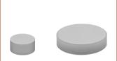
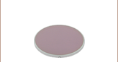
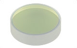
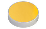
AFS-CAF
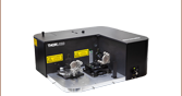
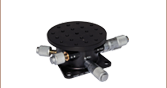
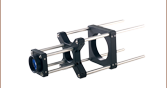
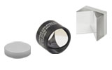
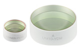
Application Idea
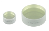
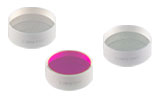
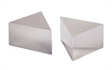
AFS-FS Prisms
on a KM100B/M


Please Wait
Figure 1.1 分散補償プリズムペア
分頂角α と分離d を持つ超短パルスレーザ分散(ULD)プリズムペアは、異なる波長成分を空間的に分散して波長依存の位相変化を起こすためにお使いいただけます。詳細は「チュートリアル」タブをご覧ください。
 Zemaxファイル Zemaxファイル |
|---|
| 下の型番横の赤いアイコン(資料)をクリックすると、各製品のZemaxファイルをダウンロードいただけます。また、こちらからは当社の全てのZemaxファイルの一括ダウンロードが可能です。 |

特長
- 設計スペクトル範囲: 700~900 nm
- 頂角公差: ±15 arcmin
- 非研磨面: 平面つや消し
- 表面平面度: λ/4@ 633 nm
- 分散補償用
- 材料:フッ化カルシウム(CaF2 )、溶融石英、SF10またはN-SF14
これらの分散補償プリズムペアは、超短パルスレーザーシステムで生じるパルス広がりを、パワーを大幅に損失せずに補償するように設計されています。4種類の 高屈折率プリズム材質があるので、様々な群速度分散(GVD)数値が得られ、異なるパルス分散の条件で補償が実現できます。
用途
これらのプリズムペアは、様々な用途に使用されます。プリズムペアと共に、ナイフエッジを利用して短波長成分または長波長成分を減衰させることで、光学フィ ルタとして機能させることができます。プリズムペアをレーザ共振器内部に配置することで、波長チューニングにもお使いいただけます。これに対し、プリズム ペアは分散補償にもお使いいただけます。レーザ共振器内で光が光学素子を通過するたびに(通常「正常分散」と呼ばれる)正分散が生じます。このプリズムペ アも正分散を生じますが、この正分散は、長波長成分が2番目のプリズムを通過する際により長い距離を通過することから幾分かオフセットされます(Figure 1.1参照)。適切なプリズムペアの配置を設定することにより、負分散(通常「異常分散」と呼ばれる)を生成し、共振器内の他の素子で生じる分散を補償することが 可能です。ミラーの位相、群遅延、GDD、3次分散、4次分散などの評価については、当社の分散測定システムChromatis™のページをご覧ください。
超短パルス用光学素子の全ラインナップは「超短パルス用光学素子」タブをご参照ください。
| Item # | Material | GVDa (at 800 nm) | TODb (at 800 nm) | αc (Apex Angle) | H (mm) | B (mm) | ΘBd | Refractive Index (at 800 nm) | Scratch- Dig |
|---|---|---|---|---|---|---|---|---|---|
| AFS-CAF | CaF2e | -5 fs2/cm | -12 fs3/cm | 69.9° | 12.3 | 17.2 | ~55.0° | 1.430 | 40-20 |
| AFS-FS | Fused Silica | -16.5 fs2/cm | -20 fs3/cm | 69.1° | 12.4 | 17.0 | ~55.6° | 1.453 | 20-10 |
| AFS-SF10 | SF10e | -97.5 fs2/cm | -388 fs3/cm | 60.6° | 13.0 | 15.1 | ~59.7° | 1.711 | 20-10 |
| AFS-SF14 | N-SF14 | -113.5 fs2/cm | -473 fs3/cm | 59.6° | 13.0 | 14.9 | ~60.2° | 1.743 | 20-10 |
下のグラフは10 mm離れたプリズムペアの群速度分散ならびに3次分散の計算値です。詳細については「チュートリアル」タブをご覧ください。
プリズムペアの分散の計算
超短パルスレーザでは周波数スペクトルが広帯域にわたるため、分散補償の必要性が増してきています。 超短パルスが分散性の材料を通過する際は、パルスは材料の屈折率の波長依存性によって必ず広がります。 パルスの形状と幅を維持するためには、負分散のシステムが必要となります。 分散の制御には、回折格子ペアやチャープミラーなど、さまざまな方法が存在しますが、プリズムペアを使用する方法は簡単でチューナブル、かつ低損失な分散補償法になります。 プリズムペアの相対的な配置を調整することによって、分散は正の値から負の値に変化させることができます。サンプルの結果についてはFigure 4.2と4.3をご覧ください。
 Figure 4.1 頂角がα、距離がdの超短パルスレーザ用分散補償プリズムペアは、異なる波長成分を空間的に分散させ、波長に依存した位相変化をもたらすことができます。
フーリエ解析を通して実証される通り、超短パルス(small Δt)は、本質的に広帯域の周波数スペクトル(large Δf)を有しています。 しかし、屈折率の波長依存特性によって、長波長のパルスは短波長のパルスよりも光学材料をより速く通過します。 そのため、フェムト秒パルスは、群速度分散(GVD)の結果としてパルス広がりの影響を受けます。 こうした効果は、このページでご紹介しているように、超短パルスレーザのパルス持続時間を短くするための負分散システムを生じさせるプリズムペアを使用することによって、逆転させることが可能です。
透過率を最大にしながら特定のGVD値を達成するためには、光は最初のプリズム面にブリュースタ角(ΘB) で入射する必要があります。 Figure 4.1で示されているように、最初のプリズムはさまざまな波長成分を分離するために使用されます。 2つ目のプリズムは、反射した光線のさまざまな波長が互いに平行に伝播して出射するよう配置されます。 さらに、もう1つのプリズムペア(合計4つのプリズム)を加えることで、最後の光線はすべて入射光路と同一線上に伝播するようにできます[1]。 この特性は、既存の光学系に分散補償の機能を組み込む際に特に便利です。
ULDプリズムペアの頂角は、p偏光の光の反射率を最小にするために、入射角および出射角の両方がブリュースタ角(ΘB)に近づくよう選択されています。
周波数依存出射角Θf(ω)は以下の式によって求められます。
ここで、nはプリズムの材料の周波数依存屈折率、ΘBは最初のプリズム表面への入射角、αはプリズムの頂角を表しています。
プリズムペア内の累積位相φ(ω)は以下の式で求められます。
ここで、ωは周波数、dはプリズム間の距離、Θfは出射角(周波数に依存)、Θfshortは最短波長の出射角を表しています。
周波数に対する1次、2次、3次の累積位相の微分係数は、それぞれプリズムペアの群遅延(GD)、群速度分散(GVD)、3次分散(TOD)に比例します。

Figure 4.2と4.3は、距離(d)が10 mm、入射角が材料のブリュースタ角(ΘB、概算値は「仕様」タブを参照)と同じプリズムのGVDおよびTODの計算値を示しています。
Click to Enlarge
Click Here for Raw Data
Figure 4.2 プリズムと様々な材料のGVD値(計算値)。距離10 mmと材料のブリュースタ角に等しい入射角を用いて計算されました。
Click to Enlarge
Click Here for Raw Data
Figure 4.3 プリズムと様々な材料のTOD値(計算値)。距離10 mmと材料のブリュースタ角に等しい入射角を用いて計算されました。
フェムト秒パルスレーザ用ならびにピコ秒レーザ用光学素子を幅広くご用意しています。詳細は下表をご参照ください。
| Dielectric Mirror | High-Power Mirrors for Picosecond Lasers | Metallic Mirrors | Low-GDD Pump-Through Mirrors | ||
|---|---|---|---|---|---|
 |  |  |  |  |  |
| Dual-Band Dielectric Mirror, 400 nm and 800 nm | Ytterbium Laser Line Mirrors, 250 nm - 1080 nm | Ultrafast-Enhanced Silver Mirrors, 750 - 1000 nm | Protected Silver Mirrors, 450 nm - 20 µm | Unprotected Gold Mirrors, 800 nm - 20 µm | Pump-Through Mirrors, 1030 - 1080 nm and 940 - 980 nm |
| Deterministic GDD Beamsplitters | Low-GDD Harmonic Beamsplitters | Low-GDD Polarizing Beamsplitters | β-BBO Crystals | Dispersion-Compensating Optics | |
|---|---|---|---|---|---|
 |  |  |  |  |  |
| Beamsplitters & Windows, 600 - 1500 nm or 1000 - 2000 nm | Harmonic Beamsplitters, 400 nm and 800 nm or 500 nm and 1000 nm | High-Power, Broadband, High Extinction Ratio Polarizers, 700 - 1300 nm | β-BBO Crystals for Second Harmonic Generation | Dispersion-Compensating Mirrors, 650 - 1050 nm | Dispersion-Compensating Prisms, 700 - 900 nm |
プリズムのセレクションガイド
当社では、光の反射、反転、回転、分散、偏向、コリメートなどのために、様々なプリズムをご用意しています。下記に掲載されていないプリズムのタイプや基板などについては、当社までお問い合わせください。
ビームステアリング用プリズム
| プリズム | 材質 | 偏向 | 反転 | 逆転または 回転 | 図解 | 用途 |
|---|---|---|---|---|---|---|
| 直角プリズム | N-BK7, UV溶融石英(UVFS), フッ化カルシウム(CaF2), セレン化亜鉛(ZnSe) | 90° | 90° | No | 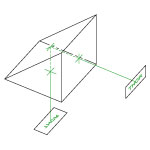 | 90°リフレクタで、望遠鏡やペリスコープなどの光学システムに使用可能 |
| 180° | 180° | No | 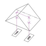 | 180°リフレクタで、入射光角に無依存。 非反転ミラーで、双眼鏡で使用可能。 | ||
| 内部全反射型 レトロリフレクタ (マウント無し、 マウント付き) 鏡面反射型 レトロリフレクタ (マウント無し、 マウント付き) | N-BK7 | 180° | 180° | No |  | 180°リフレクタで、入射光角に無依存。 ビームアライメントやビームデリバリで使用。向きの制御が難しい状況でミラーの代替品として使用可能 |
| マウント無し ペンタプリズム および マウント付き ペンタプリズム | N-BK7 | 90° | No | No |  | 90°リフレクタで、ビームプロファイルの逆転や反転無し。 アライメントや光調整に使用可能。 |
| ルーフプリズム | N-BK7 | 90° | 90° | 180o 回転 | 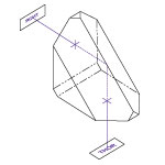 | 90°リフレクタで、像を反転し回転(像が左右上下反対になります)。 アライメントや光調整に使用可能。 |
| マウント無し ダブプリズム および マウント付き ダブプリズム | N-BK7 | No | 180° | 2回のプリズム回転 | 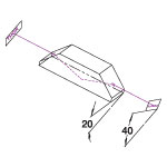 | ダブプリズムは、光の入射面によって像を反転、逆転または回転します。 ビーム回転子の回転方向を決定 |
| 180° | 180° | No | 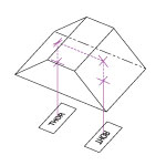 | 非逆転ミラーとして機能するプリズム 光学系におけるレトロリフレクタや直角(180°偏向)プリズムと同じ特性。 | ||
| ウェッジプリズム | N-BK7 | 2°~10°のモデル | No | No |  | ビームステアリング用途。 1つのウェッジプリズムを回転するとき、光線を偏向角の2倍の角度で円に沿って動かすことが可能。 |
| No | No |  | 可変ビームステアリングへの応用。 両方のウェッジを回転した時、光線を、偏向角の4倍の角度で円弧状に動かすことが可能。 | |||
| プリズムカプラ | ルチル(TiO2) またはGGG | 可変a | No | No | 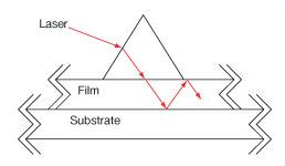 | 光をフィルムに向けて結合するために屈折率の高い基材を使用。 ルチルは nfilm > 1.8に使用。 GGGは nfilm < 1.8に使用。 |
分散プリズム
| プリズム | 材質 | 偏向 | 反転 | 逆転または 回転 | 図解 | 用途 |
|---|---|---|---|---|---|---|
| 等辺プリズム | F2, N-F2、N-SF11, フッ化カルシウム, セレン化亜鉛(ZnSe) | 可変a | No | No |  | 分散プリズムは回折格子の代替が可能。 白色光を可視領域に分岐するために使用。 |
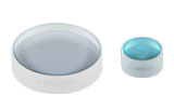
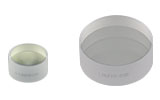
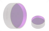
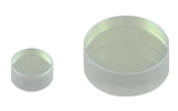
| 分散補償 プリズムペア | UV溶融石英, フッ化カルシウム(CaF2), SF10, N-SF14 | 可変式垂直オフセット | No | No | 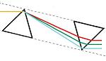 | 超短パルスレーザーシステムにおけるパルス広がりの補償。 分散補償や波長調整用の光学フィルタとして使用可能。 |
| ペロン・ブロカ プリズム | N-BK7, UV溶融石英, フッ化カルシウム | 90° | 90° | No | 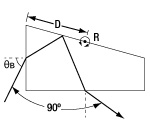 | 光線の波長分離に使用。90°の位置で出射。 レーザ高調波の分離、群速度分散の補償に使用。 |
ビーム操作用プリズム
| プリズム | 材質 | 偏向 | 反転 | 逆転または 回転 | 図解 | 用途 |
|---|---|---|---|---|---|---|
| アナモルフィック プリズムペア | N-KZFS8, N-SF11 | 可変式垂直オフセット | No | No | 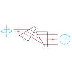 | 単軸に沿った可変倍率。 楕円形ビームのコリメートに使用(例:半導体レーザ)。 入射ビームを単軸に縮小・拡大して、楕円形ビームを円形ビームに変換。 |
| 円錐(アキシコン)レンズ(UVFS, ZnSe) | UV溶融石英(UVFS)またはセレン化亜鉛(ZnSe) | 可変a | No | No |  | コリメート光源からベッセル型の強度プロファイルの円錐状の非発散ビームを生成。 |
偏光状態変更用プリズム(偏光子)
| プリズム | 材質 | 偏向 | 反転 | 逆転または 回転 | 図解 | 用途 |
|---|---|---|---|---|---|---|
| グランテーラ、 グランレーザ、α-BBO グランレーザ偏光子 | グランテーラ: 方解石 グランレーザ: α-BBO, 方解石 | p 偏光 - 0° s 偏光 - 112°a | No | No |  | プリズムを2個使った構成と複屈折方解石を使用し、非常に消光比の高い直線偏光を生成。 プリズムの境目でs偏光が完全に内部反射されるのに対し、p偏光は透過。 |
| ルチル偏光子 | ルチル(TiO2) | s偏光 - 0° p偏光は筐体によって吸収 | No | No |  | プリズムを2個使った構成と複屈折ルチル(TiO2)を使用し、非常に消光比の高い直線偏光を生成。 プリズムの境目でp偏光が完全に内部反射されるのに対し、s偏光は透過。
|
| ダブルグランテーラ偏光子 | 方解石 | p偏光 - 0° s偏光は筐体によって吸収 | No | No | 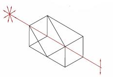 | プリズムを3個使った構成の複屈折方解石を使用し、大きな見込み角で最大の偏光効率を得る。 プリズムの境目でs偏光が完全に内部反射されるのに対し、p偏光は透過。 |
| グラントムソン 偏光子 | 方解石 | p偏光 - 0° s偏光は筐体によって吸収 | No | No | 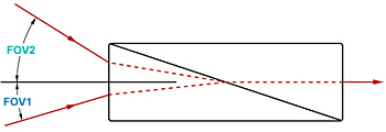 | プリズムを2個使った構成の複屈折方解石を使用し、高い消光比を維持しながら最大視野を実現。 プリズムの境目でs偏光が完全に内部反射されるのに対し、p偏光は透過。 |
| ウォラストンプリズム、ウォラストン偏光子 | 石英, フッ化マグネシウム, α-BBO, 方解石, YVO4 | 対称形のp偏光および s偏光の偏角 | No | No |  | プリズムを2個使った構成の複屈折方解石を使用し、ビーム移動偏光子で最大の偏角を実現。 s偏光とp偏光は、プリズムから対称方向に偏位。ウォラストンプリズムは分光計や偏光アナライザで使用。 |
| ロションプリズム | フッ化マグネシウム , YVO4 | 常光: 0° 異常光:偏角方向 | No | No |  | プリズムを2個使った構成でMgF2またはYVO4が小さい偏角で高い消光比をもたらします。 異常光は入力光と同じ光軸を伝搬しますが、常光は偏光しません。 |
| ビーム分離 プリズム | 方解石 | 2.7または4.0 mmのビーム移動 | No | No | 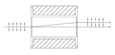 | プリズムを1個使った構成の複屈折方解石を使用し、入射ビームを2本の直交する偏光ビームに分岐。 s偏光とp偏光は2.7または4.0 mmで分離。ビーム分離プリズムは、90°分割ができない場合に偏光ビームスプリッタとして使用可能。 |
| フレネル・ロム リターダ | N-BK7 | 直線偏光から円偏光へ 垂直オフセット | No | No | 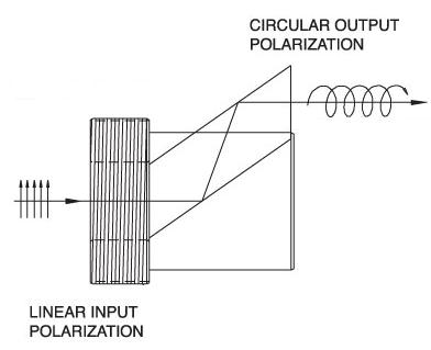 | λ/4フレネル・ロムリターダは、直線偏光入力を円偏光出力に変換。 複屈折波長板と比較して、幅広い波長でなλ/4リターダンス。 |
| 直線偏光を90°回転 | No | No | 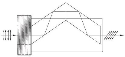 | λ/2フレネル・ロムリターダは、直線偏光を90°回転。 複屈折波長板と比較して、幅広い波長で均一なλ/2リターダンス。 |
ビームスプリッタープリズム
| プリズム | 材質 | 偏向 | 反転 | 逆転または 回転 | 図解 | 用途 |
|---|---|---|---|---|---|---|
| ビームスプリッターキューブ | N-BK7 | 分岐比50:50、0°と 90° sおよびp偏光が互いに10%以内 | No | No | 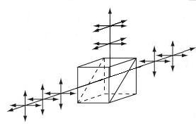 | プリズムを2個使った構成と、誘電体コーテイングにより、ほぼ偏光無依存で分岐比は50:50。 仕様波長範囲内では、無偏光ビームスプリッタとして機能。 |
| 偏光ビームスプリッターキューブ | N-BK7, UV溶融石英, N-SF1 | p偏光 - 0° s偏光 - 90° | No | No | 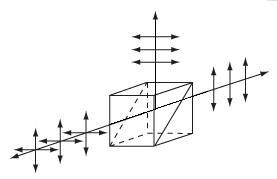 | プリズムを2個使った構成と、誘電体コーテイングにより、p偏光を透過し、s偏光を反射。 高度に偏光する際には、透過光を利用。 |
| Posted Comments: | |
Zhengru Guo
(posted 2024-07-31 13:46:16.787) The dispersion curves gived by you and Newport are so different. According to Newport, "SF10 glass prisms provide group velocity dispersion of 1600 fsec2/cm at 800 nm". However, with your curve, SF10 glass prisms provide group velocity dispersion of ~100 fsec2/cm at 800 nm. It's so different, which can I trust? jpolaris
(posted 2024-08-01 04:57:23.0) Thank you for contacting Thorlabs. The GVD and TOD data for our AFS-series prisms, including AFS-SF10, represents values for prism pairs separated by a distance of 10 mm and with an angle of incidence equivalent to the Brewster's angle of the material. These data do not represent just the substrate itself in isolation. This is discussed on our Tutorial page found at the following link. https://www.thorlabs.com/newgrouppage9.cfm?objectgroup_id=3242&tabname=Tutorial hyo s
(posted 2024-07-16 09:58:42.99) Hi! May I ask for the transmittance data within the range of 800-1000 nm, if possible? Thank you. jpolaris
(posted 2024-07-16 07:36:37.0) Thank you for contacting Thorlabs. The transmission through these dispersion-compensating prisms pairs will depend on the material substrate. We offer these prisms in four different substrates -- CaF2, fused silica, SF10, and N-SF14. I have reached out to you directly with transmission data for each of these substrates. Zhongcheng Wang
(posted 2023-12-30 00:22:50.093) Hello, may I ask, the main difference between these four prism pairs is the difference in dispersion compensation? Why are prism pairs with flat dispersion curves and smaller absolute values more expensive? Is it because something else has an advantage in terms of pulse width compression? jpolaris
(posted 2024-01-02 06:34:14.0) Thank you for contacting Thorlabs. The difference in price between the dispersion-compensating prisms that we offer is primarily attributable to the procurement costs for the various substrates. For instance, CaF2 is more expensive as a raw material than UV fused silica, SF10, and N-SF14. In terms of specifications, the CaF2 prism has a better surface quality than the prisms made from the other substrates. When making a decision on which prism to use, you would need to determine how much compensation is needed, as well as to consider the amount of space available in your setup. The accumulated phase, and therefore also GD, GVD, and TOD, is dependent on the prism spacing and substrate material. We discuss this in greater detail at the following link:
https://www.thorlabs.com/newgrouppage9.cfm?objectgroup_id=3242&tabname=Tutorial Patrick H
(posted 2023-07-11 14:31:02.993) Is the SF-14 also usable for dispersion compensation at 1064nm? cdolbashian
(posted 2023-07-21 02:02:14.0) Thank you for reaching out to us Patrick. While we do not spec performance of these components with this particular wavelength, compensation can be achieved, and tuned, by changing the inter-prism spacing, as well as the incident angles on each prism. Fundamentals of the design and operation of such a prism pair can be seen in the paper which we reference in our "tutorial" tab of that product page:
[1] R. L. Fork, O. E. Martinez, and J. P. Gordon, "Negative dispersion using pairs of prisms," Opt. Lett. 9, 150-152 (1984) Fu min
(posted 2022-06-22 10:44:47.873) I want to konw the Dispersion formula of SF10,and its reflractive index. cdolbashian
(posted 2022-06-24 03:30:42.0) Thank you for reaching out to us with this inquiry. I have contacted you directly with the appropriate information. Paul Bittorf
(posted 2021-11-29 10:14:55.527) Dear Sir or Madam, for a new ultrafast laser setup we plan to include multiple prism pairs for the fundamental (~800 nm), second and third harmonic for dispersion compensation. On your site, you present the prism pairs designed for the wavelength range of 700 - 900 nm, which is only perfect for the fundamental. Can we use the same prisms as well for the second (~400 nm) and third (~266 nm) harmonic or is there a big difference in the refractive index for such wavelengths and therefore a huge tradeoff? Also, does the material have an important impact besides the lenght of the compensator? Thank you for answering. Best regards, Paul Bittorf cdolbashian
(posted 2021-12-22 04:51:04.0) Thank you for reaching out to us Paul. These prisms can indeed be used for other wavelengths, though you would need to adjust the angle of the prisms and the inter-prism spacing. The governing equations and referenced research paper can be found on the "Tutorial" tab on this page. The material, N-BK7, has a known index of refraction which helps to determine the spacing and angle. Please feel free to reach out to us in the future with any other inquiries. John Linden
(posted 2021-06-29 14:55:53.713) Dear Rep.
I am looking for a solution to correct beam ellipticity for UV 343nm with pulsewidth of ~250fs. is this product sufficient?
I think the anamorphic prism pair is a good product but not sure of the compatability with ultrafast UV laser. Also it seems UV is not the designed wavelength for the AFS-FS as well. Appreciate any recomendation. cdolbashian
(posted 2021-07-20 01:09:05.0) Thank you for contacting us at Thorlabs. Given a 250fs pulsewidth for a laser in the UV range, a sufficient method for correcting beam ellipticity would be a pair of UV-fused silica, plano-convex lenses, rather than this prism pair. The function of this prism pair is used to correct for pulse broadening, which occurs when ultrafast pulses pass through a dispersive material. For your pulse duration, and the thickness of a standard lens of UV fused silica, the pulse broadening should be negligible. I have reached out to you directly to discuss different options. lokirune
(posted 2018-08-26 23:48:22.507) Hi. I bought this, but the size is smaller than I expected ( even I looked at the spec before I bought), so I couldn't put this in my system. Do you have other options with bigger size and coating for a lower wavelength(300nm)? If not, is it OK to buy just 2 right angle prisms? Thanks. YLohia
(posted 2018-08-27 05:59:43.0) Hello, thank you for contacting Thorlabs. We do have the ability to offer custom prism pairs, depending on your specific requirements and order quantity. Custom item orders should be placed through techsupport@thorlabs.com. We will reach out to you directly to discuss your requirements. Though an equilateral prism would likely work better, a right angle prism would work as well as long as you are prepared to solve the equations shown on the Tutorial tab of this page. lokirune
(posted 2018-05-22 22:54:09.68) about the AFS-CAF, is it OK to use with high power pulsed laser ? ( for example, 5ns 20W 532nm)
Thanks. YLohia
(posted 2018-05-23 08:59:13.0) Hello, thank you for contacting Thorlabs. Unfortunately, we do not currently have test data for our uncoated CaF2 substrates since we do not manufacture the raw material itself. The actual damage threshold is also dependent on factors such as beam diameter and repetition rate of the laser (is 20 W the peak power or the average power?). That being said, CaF2 is general considered to be a "high damage threshold" material and is used in high power pulsed applications so it is likely for this to work for you, though we cannot provide any guarantees due to the lack of data. user
(posted 2017-05-30 16:01:15.873) Will these prisms work at longer wavelengths - e.g. in the range 2-3 micrometers? Do you offer any AR coated options please? tfrisch
(posted 2017-06-22 09:09:11.0) Hello, thank you for contacting Thorlabs. We can offer these with other coatings, but at longer wavelengths, the distance between the prisms will need to be increased to compensate for the lower dispersion of the substrate. Please contact TechSupport@Thorlabs.com to discuss the requirements of your custom application. ethewalt
(posted 2015-11-05 13:20:59.727) The GVD graph on the dispersion-compensating prism pair page needs to be fixed. The labels for fused silica and calcium fluoride are interchanged, and the horizontal gridlines don't correspond to the GVD axis labels. besembeson
(posted 2015-11-05 01:48:40.0) Response from Bweh at Thorlabs USA: Thanks for bringing this to our attention. We are going to fix the graphs on the website. user
(posted 2015-08-25 22:07:19.71) There is a typo in the formula for theta_f in the tutorial. There is an "arcsin" and an "asin". Choose one :) myanakas
(posted 2015-08-28 03:48:27.0) Response from Mike at Thorlabs. Thank you for your feedback. This typo has been corrected and we apologize for any inconvenience this may have caused. tianzhushang
(posted 2013-08-22 14:50:37.537) I've bought the AFS-SF14,How could I set the length between the two prisms and Can you e-mail me the data with the method to calculate it? jlow
(posted 2013-09-17 17:06:00.0) Response from Jeremy at Thorlabs: We have a sample calculations PDF linked in the "Specs" tab on our website. Our web team is looking to re-post a revised, updated version which should be clearer. We will contact your directly to discuss about this in more detail. 357510589
(posted 2012-10-16 09:50:54.14) 您好,刚看了贵公司的色散补偿棱镜,在这里有两张图,分别为二阶、三阶色散因子图,请问这个图是指单纯的材料色散吗?(即仅与材料组成有关,与棱镜外形及空间位置无关),另外,在使用此棱镜对,进行色散补偿时,根据你们的教程,没看太明白,能否提供更详细的教程不?期待着您好回复,谢谢! bdada
(posted 2011-10-07 18:19:00.0) Response from Buki at Thorlabs:
Thank you for your feedback. We will be happy to provide you with this data or the appropriate method to calculate it. We need the part number of the prism pair you are using and the configuration of the prisms.
We also have MathCad files for some of our dispersion prisms that we have emailed to you. Please contact TechSupport@thorlabs.com if you have further questions. avle
(posted 2011-09-26 23:55:36.0) Hi there,
I was wondering how we would calculate the negative dispersion parameter for a given prism set, with known optical properties and geometric configuration of the prism pair?
The dispersion parameter in units of ps/nm
Thanks! jjurado
(posted 2011-06-24 18:27:00.0) Response from Javier at Thorlabs to lionel.tombez: Thank you very much for contacting us. The AFS-SF10 dispersion compensation prism pairs will certainly transmit well at 1.1um. The prisms are cut at the same angle as Newport's prisms, so the performance will be identical. lionel.tombez
(posted 2011-06-23 09:08:08.0) Can one use these prisms (SF10) to compress 1.1 um pulses ? I dont get the difference with Newport prism compressor product, which is of the same material (SF10) but specified up to 2.3um.
Thanks Customer Email: lionel.tombez@unine.ch This customer would like to be contacted. Greg
(posted 2011-01-11 10:23:19.0) A response from Greg at Thorlabs to william.t.lotshaw: Thank you for pointing out this error. The graphs were incorrect and have been fixed. william.t.lotshaw
(posted 2011-01-10 11:22:58.0) The GVD and TOD curves for fused silica and CaF2 appear to be reversed in the graphs tab if the values you list in the overview for the Brewster dispersion compensation prisms is correct Javier
(posted 2010-06-17 10:39:21.0) Response from Javier at Thorlabs to jessew: our specifications list the total TOD for the prism compressor. We derived the GVD and TOD values based on accumulated phase of the prism compressor. I can send you a document which outlines the derivation for these values. jessew
(posted 2010-06-16 23:08:50.0) Im unclear on how the numbers for TOD were derived for the prism pairs. Is the material TOD listed, or total TOD for a compressor constructed out of the prism pair?
For example, using the standard definition of material TOD as the third derivative of wave number k with respect to angular frequency omega, TOD for SF10 should be 0.10 fs^3/rad per micrometer of material propagation.
Thanks,
-Jesse Wilson |