 Products Home
精密回転ステージ
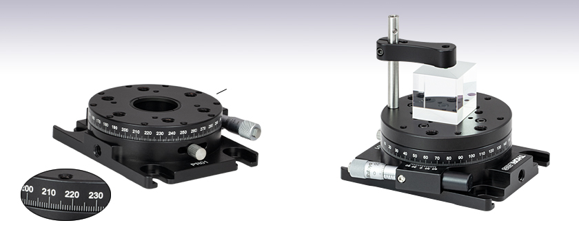
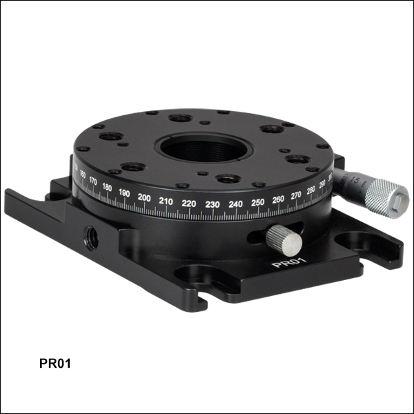
- Continuous 360° Manual Rotation
- Micrometer and Vernier Scale Provide 5 arcmin Resolution
- Mount Horizontally or Vertically
Ø0.94" (Ø23.9 mm) Clear
Aperture with SM1 Threading
PR01
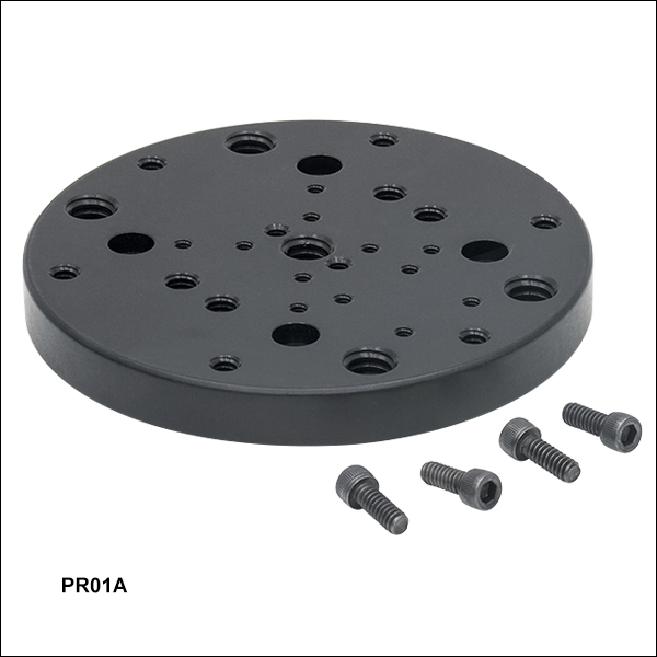
Cube Beamsplitter on
PR01A Adapter Plate,
Held with PM4 Clamping Arm


Please Wait
| Specifications | ||
|---|---|---|
| Item # | PR01(/M) | |
| Coarse Rotation Range | 360°, Continuous | |
| Fine Adjustment Range | ±5° | |
| Clear Aperture | Ø0.94" (Ø23.9 mm) | |
| Horizontal Load Capacity | Overall: 25 lbs (11.4 kg) Fine Adjustment: 3.75 lbs (1.7 kg) | |
| Vertical Torque Capacitya | 8.28 lb-in (0.93 N·m) | |
| Platform Dimension | Ø2.7" (Ø68.6 mm) | |
| Platform Mounting Holes | 1/4"-20 (M6) (6 Places) 6-32 (M4) (10 Places) 4-40 (4 Places) | |
| Platform Height | 1.0" (25.3 mm) | |
| Base Dimensions | 2.75" x 3.5" (69.9 mm x 88.9 mm) | |
| Base Mounting Features | Mounting Slot for 1/4"-20 (M6) Cap Screws (4 Places) | |
| 1/4"-20 (M6) Taps for Vertical Mounting (2 Places) | ||
微動回転画可能です。
特長
- 360°の連続粗動回転
- マイクロメータおよびバーニヤ目盛による ±5°の微調整
- 1° 毎に目盛をレーザ刻印
- 標準のオプトメカニクス用タップ穴、30 mmケージシステム用クランプアームまたはロッド
- 中心穴にはSM1ネジ付き
- 光学素子、移動ステージ、ゴニオメータ、回転ケージシステム用取付けアダプタ
- 耐荷重:11.4 kg
当社の精密回転ステージPR01/Mは、大きめの光学素子やオプトメカニクスアセンブリを精密かつ微細に回転させることができます。右の動画のように、スチール製の固定つまみネジが固定されていない状態のときは、ステージを手動で連続的に滑らかに回転させることが可能で、ステージ側面の1°単位の目盛を 使って回転を測定することができます。 つまみネジが固定されている状態のときは、±5ºのマイクロメータにより微調整され、バーニヤ目盛りにより5 arcmin分解能で測定されます。
右でご覧いただけるようにこちらの回転ステージには、標準的なオプトメカニクス、クランプアーム(下記参照)、当社の30 mmケージシステムを取り付けるためのM6、M4ネジ穴やケージロット取付用のネジ穴が付いています。また、4つのM6ザグリ貫通スロットを用いて光学テーブルやブレッドボードに取り付けられます。
アダプタープレート
SM1ネジ切り穴のない回転プラットフォームが必要な用途には、アダプタープレートPR01A/M をお使いください。 回転ステージPR01/Mの上部に取り付け、1軸および2軸ゴニオメータや小型移動ステージへの取付け用にタップ穴を増やすことができます。 また、上部の図のように、クランプアームと一緒に使用して光学素子を保持することも可能です。
30 mmケージシステム用回転アダプタ
このアダプタは2個の30 mmケージロッドを回転軸と垂直な平面内に位置固定することが可能です。 回転ステージPR01/Mと組み合わせると、30 mmケージセグメントを360°フル回転させ、ステージのマイクロメータを利用して精密に位置を調整することが可能です。
バーニヤ目盛の読み方:主目盛が直線状の場合
バーニヤ目盛は、均等に分割された標準的な目盛(当社の回転マウント、ゴニオステージ、移動マウントに付いている目盛など)に対して、精密さを向上させるために一般的に使用されている目盛です。バーニヤ目盛は多くの精密測定器に使用されていますが、中でも良く知られているのはノギスやマイクロメータです。バーニヤ目盛を使用するときは、主目盛とバーニヤ目盛の2つの目盛を並べて使用します。バーニヤ目盛は、主目盛のN - 1目盛に対してN目盛が対応するように刻まれているため、その間隔は主目盛よりも若干狭くなります。そのため、主目盛の刻線とバーニヤ目盛の刻線とは一致しません。バーニヤ目盛の刻線で主目盛の刻線と最も良く一致するのは通常1本だけですが、それがバーニヤ目盛を読む要所になります。
図1~3では、直線状のバーニヤ目盛の仕組みについて3つの例をあげて説明しています。これらの図では、左側が主目盛で右側の小さい目盛がバーニヤ目盛です。バーニヤ目盛を読むときは、まず主目盛で大まかな数値を読み取り、次にバーニヤ目盛で精密な数値を読み取ります。この仕組みで、標準的なルーラやマイクロメータが精密な測定器になります。
バーニヤ目盛の0は「ポインタ」(図1~5で赤い矢印で表示)で、主目盛での読取値を示します。図1では、ポインタは主目盛の75.6の刻線と一致しています。これ以外で主目盛の刻線と一致しているバーニヤ目盛の刻線は、10だけであることに注目してください。ポインタが主目盛の75.6と一致しているので、図1から読み取れる値は75.60になります(どのような単位での測定でも同じです)。
これがバーニヤ目盛の読み取り方の基本です。バーニヤ目盛を用いると、簡単に測定器の精度を向上させることができます。図2で更に詳しくご説明します。ここではポインタは主目盛の刻線とは一致せず、75.6よりわずかに上側ですが75.7よりも下側にあります。この場合の大まかな読取値は75.6になります。主目盛と最も良く一致するバーニヤ目盛は5で、青い矢印で示されています。バーニヤ目盛は精密に読み取れる最小桁を示し、図2では5が主目盛と一致しているので、精密な測定値は75.65になります。
バーニヤ目盛は主目盛よりも10%小さくなっているので、バーニヤ目盛を主目盛の1/10だけ動かすと、バーニヤ目盛の次の刻線が一致します。ここで、測定値が1/10の精度を与えてくれるバーニヤ目盛の間にきてしまった場合はどうするのか、という疑問が生じます。図3ではこれについて説明しています。上述の通り、ポインタの刻線は75.6と75.7の間にあるので、大まかな読取値は75.6になります。よく見ると、バーニヤ目盛の7(青い矢印で表示)が主目盛とほぼ一致しているので、精密な測定値としては75.67になります。しかし、バーニヤ目盛の7は主目盛よりもわずかに上にあり、8(7のすぐ上)は主目盛よりもわずかに下にあります。このことから、図3の目盛は75.673 ± 0.002と読み取れます。この想定器では、読取誤差を約0.002とするのは適切です。
Click to Enlarge
図1:バーニヤ目盛の読み取り方の例。赤い矢印はポインタと呼ばれています。バーニヤ目盛の10が主目盛の1本と一致しているので、このバーニヤ目盛は75.60と読み取れます(どのような単位での測定でも同じです)。
Click to Enlarge
図2:赤い矢印はポインタを示し、青い矢印は主目盛と一致するバーニヤ目盛の刻線を示しています。この目盛では75.65と読み取れます。

Click to Enlarge
図3:赤い矢印はポインタを示し、青い矢印は主目盛と一致するバーニヤ目盛の刻線を示しています。これは75.67と読み取れますが、より精密には75.673 ± 0.002と読むことができます。
バーニヤ目盛の読み方:主目盛が回転式の場合
バーニヤ目盛は、主目盛とバーニヤ目盛が単位を共有していない回転式の目盛でも使用できます。図4と図5では、主目盛には度(°)を単位とする刻線があり、バーニヤ目盛には5 arcmin(60 arcmin = 1°)毎の刻線がある場合について、2つの例をあげて説明しています。これらの図では、上が主目盛を表し、下の小さい目盛がバーニヤ目盛を表します。
図4では、ポインタは主目盛の341°の刻線と一致しています。これ以外に主目盛と一致しているバーニヤ目盛は±60 arcminだけであることに注目してください。バーニヤ目盛の0が主目盛の341°と一致しているので、図4から読み取れる値は341.00°になります。
バーニヤ目盛の0が主目盛の2本の刻線の間にある場合は、2通りの読み取り方ができます。1つ目の方法では、ポインタの左側で主目盛と一致しているバーニヤ目盛の刻線を読み取り、その値(単位はarcmin)をポインタのすぐ右側にある主目盛の値から引きます。例として、図5ではバーニヤ目盛のポインタは342°と343°の間にあります。バーニヤ目盛の左側の青い矢印を使用して読むと、343° - 15 arcmin = 342.75°になります。2つ目の方法は、バーニヤ目盛のポインタの右側にある青い矢印から読み取った値を、主目盛のポインタより左側の小さな値に加える方法です。図5の右側の青い矢印を使用して読むと、342° + 45 arcmin = 342.75°になります。
このように、バーニヤ目盛を用いると標準的なスケール測定の精密さを向上させることができます。慣れるまでに少々時間がかかりますが、練習すれば非常に簡単に目盛を読めるようになります。順バーニヤ、逆バーニヤ*にかかわらず、すべてのバーニヤ目盛は同様の方法で読み取ることができます。
*逆バーニヤ目盛は目盛の間隔が主目盛よりも若干広く、主目盛のN + 1目盛に対してN目盛が対応するように刻まれています。

Click to Enlarge
図4: 主目盛の単位(度)とバーニヤ目盛の単位(arcmin)が異なる例。赤い矢印はポインタを示しています。この目盛では341.00°と読み取れます。
Click to Enlarge
図5:赤い矢印はポインタを示し、青い矢印はバーニヤ目盛で読み取れる精密な数値を示します。 この目盛では342.75°と読み取れます。
| Posted Comments: | |
María Sánchez Hernández
(posted 2025-04-08 08:21:37.91) Good morning,
I am writing to ask if with this adapter plate it would be possible to use a metric post holder on the high precision rotation stage (by fixing the plate to the stage by the contour).
Thanks in advance,
María jdelia
(posted 2025-04-10 04:40:13.0) Thank you for contacting Thorlabs. Yes, you can mount a metric post holder with an M6 tapped hole at the bottom to the PR01A/M. You would just need to mate it to the M6 hole in the center of the adapter plate using an M6 set screw. Marcin Sleczka
(posted 2022-04-27 12:15:39.133) Dear Thorlabs Crew,
I have notice that with the PRO1A/M stage four screws with metric thread but for imperial hex key are included.
It is surprising for me. I do not have such key because I use metric standard.
Best regards,
Marcin jdelia
(posted 2022-05-12 03:25:35.0) Thank you for contacting Thorlabs. The four screw that come with the PR01A/M are imperial 4-40 screws to mate with the 4-40 mounting holes on the PR01(/M). The reasoning behind this is so that the stage is compatible with our 4-40 threaded ER- series cage rods. We than you for bringing to the light the issue that it is difficult to adjust these screws if you only have metric hex keys, and apologize for the inconvenience you are experiencing. We have reached out to you directly regarding potential solutions. Rajeev Sharma
(posted 2021-10-26 14:14:28.27) Hi,
Greetings from Keysight Technologies!
There is no RoHS CoC available for this part on your website. Could you please provide RoHS CoC as per directive 2015/863? Thanks!
Regards,
Rajeev Sharma YLohia
(posted 2021-12-23 10:50:12.0) Hello Rajeev, thank you for contacting Thorlabs and bringing this to our attention. I have reached out to you directly with a pdf of the RoHS and we have updated the webpage to include this information. Edmond Chehura
(posted 2019-07-26 07:31:47.68) Is it possible to replace the manual micro-adjuster with a motorized actuator? If so, which motorized actuator? YLohia
(posted 2019-07-26 11:18:01.0) Thank you for contacting Thorlabs. Unfortunately, this stage cannot be motorized. We recommend using the HDR50 for such applications. If your load is very light, you can use the PRM1Z8. david.sommitz
(posted 2018-07-25 15:43:54.193) These are great for making relative angular measurements! Is there any way to adjust the absolute rotation state so that a reading of 0 degrees on the instrument is parallel/perpendicular to one of the three sets of 1/4-20 holes? The absolute position seems arbitrary as is. llamb
(posted 2018-07-27 05:55:47.0) Thank you for your feedback. The main rotating body of the PR01 is designed so that the 0°/180° engravings line up with the center line of 1/4"-20 and #6-32 holes. Refer to the PR01(/M) schematic image where the two pairs of holes are aligned vertically and would match the 0°/180° engravings on the side. You can fine adjust your micrometer to your desired "0" position while the PR01(/M) is locked, and then while unlocked you can manually adjust the stage to align the 0 engraving where needed. chrisb
(posted 2018-07-02 21:59:26.087) What is the Backlash for this stage? llamb
(posted 2018-07-13 02:24:59.0) Thank you for contacting Thorlabs. The PR01(/M) stage will not have any backlash for coarse adjustment, as the mounting platform rotates about an internal ring. Fine adjustment is driven by our 148-206ST micrometer which uses a fine adjustment screw. Because this micrometer's adjustment screw is preloaded by a spring force, fine adjustment will have negligible backlash. kwon0512
(posted 2017-10-24 16:58:55.843) Hi,
What is difference between CR1 and PR01A tfrisch
(posted 2017-10-30 02:00:24.0) Hello, thank you for contacting Thorlabs. The biggest functional difference is that CR1 uses a worm gear for travel and a vernier scale to achieve 10arcsec resolution where the PR01 (the stage used with the PR01A top plate) is directly rotated by hand for coarse adjustment and uses a micrometer with 2.4arcsec resolution for the fine adjustment. I will reach out to you directly to discuss these stages further. skooi
(posted 2017-06-09 10:52:39.85) Hi,
If I put a longer travel distance micrometer on this stage, would I be able to get a greater range of precision angles? I would like a longer that +-5 degrees of high precision travel.
Thanks,
Steve. tfrisch
(posted 2017-06-22 04:22:28.0) Hello, thank you for contacting Thorlabs. While PR01 is not compatible with a larger micrometer, the vernier scale can be used to finely measure the position at any point in the rotation of the stage. This will require coarse adjustment between ranges, but the position can then be finely set. I will reach out to you directly to discuss your application. cadatte
(posted 2015-04-09 15:55:06.82) Hello,
I would like to use the unit outside, even if it is raining. Will the unit support water?
Thank you, Cyril jlow
(posted 2015-04-14 11:30:40.0) Response from Jeremy at Thorlabs: The rotation mount is not sealed to be waterproofed so water could get into the internal components of the mount. This will degrade the grease used inside and you will probably not get smooth movement. It will also potentially expose the internal components to corrosion. medmonds
(posted 2015-03-30 18:15:02.957) Hello,
Is there a users manual for this rotational stage? The mounting scheme and the adjustments seem skewed and difficult for some people using this. The zero point seems to be in an odd place. People are wondering whats the standard intended use and setup. Any information is appreciated.
Thanks
Mike cdaly
(posted 2015-03-31 01:53:44.0) Response from Chris at Thorlabs: I'm afraid there is no manual for the PR01(/M), but hopefully this explanation will provide enough clarity. The rotating platform in the middle is free to rotate manually when the thumbscrew is unlocked. Threading down the thumbscrew secures the rotating platform to an interior moving ring. This ring has a small level arm attached which is mounted between a compression spring and linear micrometer. Moving the micrometer in or out will push on this arm, rotating the ring inside. When the thumbscrew is tightened this will in-turn move the rotating platform along with the ring. The location of the zero position when using the micrometer driven fine adjustment is dependent on where the rotating platform was manually positioned before the thumbscrew was locked down. This course adjustment, the manual movement of the platform without the thumbscrew locked down can be done over a continuous 360 degree range, while the fine adjustment can only be used over a +/- 5 degree range. h.vennekate
(posted 2014-09-12 07:59:04.567) I'm not quite sure how the calibration of the micrometer's graduations to the vernier scale is gonna work out. Can you give any more detailed advice on that one? jlow
(posted 2014-09-18 03:58:27.0) Response from Jeremy at Thorlabs: The angular rotation is not linear with the linear translation of the micrometer. You would have to record the amount of rotation for a number of distances the micrometer has moved and then fit a curve onto the points you recorded. We will contact you directly to discuss more about this. patrick.hallen
(posted 2014-05-16 11:19:58.073) We are planning to use the PR01/M in a vertical configuration and want to attach a rather heavy setup to it. What is the torque limit of the PR01/M (i.e. what is the limit for the vertical attachment of heavy/large objects). cdaly
(posted 2014-05-22 11:53:27.0) Response from Chris at Thorlabs: The torque limit of the stage is 0.69 foot pounds (0.93 N m). It is intended to have the center of mass as close as possible to the center of rotation. marek.mikloska
(posted 2014-05-15 16:36:51.173) Is it possible to use this mount in production environment - CNC machine ? It would be exposed to leaking of coolant - ispoarafinic hydrocarbon spraymist mixed with germanium dust. Is it possible to mount GNL18/M - Large Goniometer on this rotational stage ? Thank you for your answer. Marek cdaly
(posted 2014-05-22 10:34:03.0) Response from Chris at Thorlabs: The GNL18/M can be mounted to the metric stage PR01/M. You can use M6 cap screws through the 50 mm separated slots on the goniometer and into any two opposing M6 holes on the platform of the PR01/M. There will only be one screw in each slot, so you will need to align it manually if you want this centered about the axis of rotation. As for the environment, I cannot recommend using this when there is a strong possibility of getting debris into the inner workings of the stage. petr.hlavenka
(posted 2013-12-02 05:06:03.58) Please can you specify the wobble (or paralellism) and concentricity over 360deg rotation. Is its the same as for CR1/M-Z7 model?
Thanks,
Petr cdaly
(posted 2013-12-05 10:08:21.0) Response from Chris at Thorlabs: Thank you for using the feedback tool. The worst case parallelism from the mounting surface to the rotation dial is – 0.001”. The worst case potential wobble of the rotation dial to the mounting plate is 2mrad. Worst case concentrically of the dial to the mounting plate would be 0.00075". Throlabs
(posted 2010-07-23 11:10:25.0) Response from Javier at Thorlabs to andrgrimes: Thank you very much for your feedback. I will discuss your comments with our mechanics department. We are constantly looking to improve our products, so we will certainly take this into account when designing a new version of the PR01 rotation stage. andrgrimes
(posted 2010-07-22 12:42:17.0) This is a very poorly designed product below are a list of faults I saw when trying to use the PR01.
1. The locking screw is in a bad place and too small and cheap feeling, making it very hard to lock this stage in place.
2. This product is listed as a related product in the goniometer section, how ever the awkward mounting dimensions for both of them did not allow for the goniometer and rotation stage to be mounted on the same axis.
3. The micrometer has a substantial amount of wind up making it difficult to make precise adjustments around a point.
4. The mounting slots are at an awkward 2 1/2" x 3" and they are slotted making it difficult to mount vertically.
Overall this product leads to many headaches when setting up and disappointment when it is set up you realize that it does not work as expected. The Newport rotation stages are much better in every way possible. |
回転マウント&回転ステージのセレクションガイド
当社では手動式および電動式の回転マウントと回転ステージを豊富にご用意しております。回転マウントの内孔はØ12 mm~Ø12.7 mm(Ø1/2インチ)、Ø25 mm~Ø25.4 mm(Ø1インチ)、またはØ50 mm~Ø50.8 mm(Ø2インチ) の光学素子取付け用に設計されております*。また回転ステージには、様々な部品やシステムが取り付けられるようにタップ穴が配置されております。電動式は、DCサーボモータ、2相ステッピングモータ、あるいはElliptec™共振ピエゾモータにより駆動されます。いずれも360°の連続回転が可能です。
*下表のマウントは、Ø12.7 mm、Ø25.4 mm、Ø50.8 mmの光学素子に対して最適設計されています。Ø12.0 mm、Ø25.0 mm、Ø50.0 mmなどの少し小さい光学素子に対してもご使用いただけますが、光学素子の偏心が重要ではない用途でのご使用をお勧めします。
手動回転マウント
| Rotation Mounts for Ø1/2" Optics | |||||||
|---|---|---|---|---|---|---|---|
| Item # | MRM05(/M) | RSP05(/M) | CRM05 | PRM05(/M)a | SRM05 | KS05RS | CT104 |
| Click Photo to Enlarge |  |  |  |  |  |  |  |
| Features | Mini Series | Standard | External SM1 (1.035"-40) Threads | Micrometer | 16 mm Cage-Compatible | ±4° Kinematic Tip/Tilt Adjustment Plus Rotation | Compatible with 30 mm Cage Translation Stages and 1/4" Translation Stagesb |
| Additional Details | |||||||
| Rotation Mounts for Ø1" Optics | ||||||||
|---|---|---|---|---|---|---|---|---|
| Item # | RSP1(/M) | LRM1 | RSP1D(/M) | DLM1(/M) | CLR1(/M) | RSP1X15(/M) | RSP1X225(/M) | PRM1(/M)a |
| Click Photo to Enlarge |  |  | 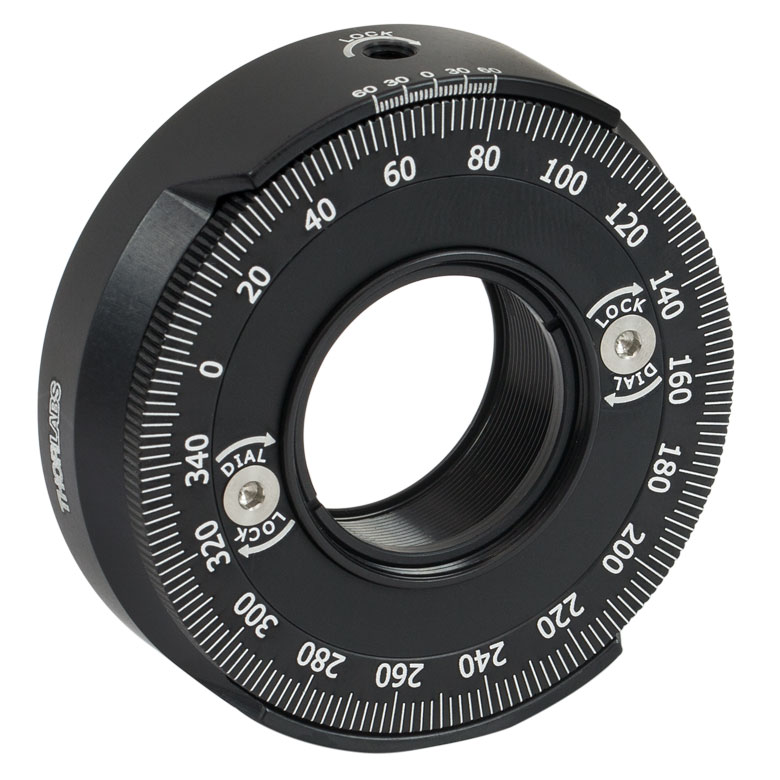 | 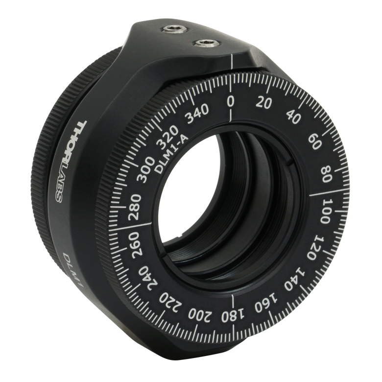 | 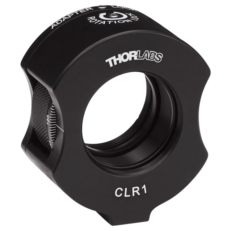 | 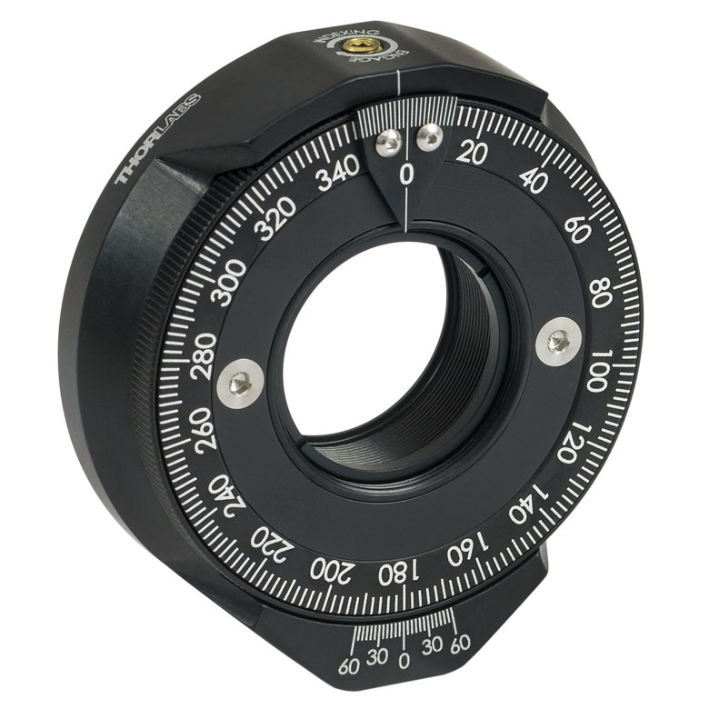 | | 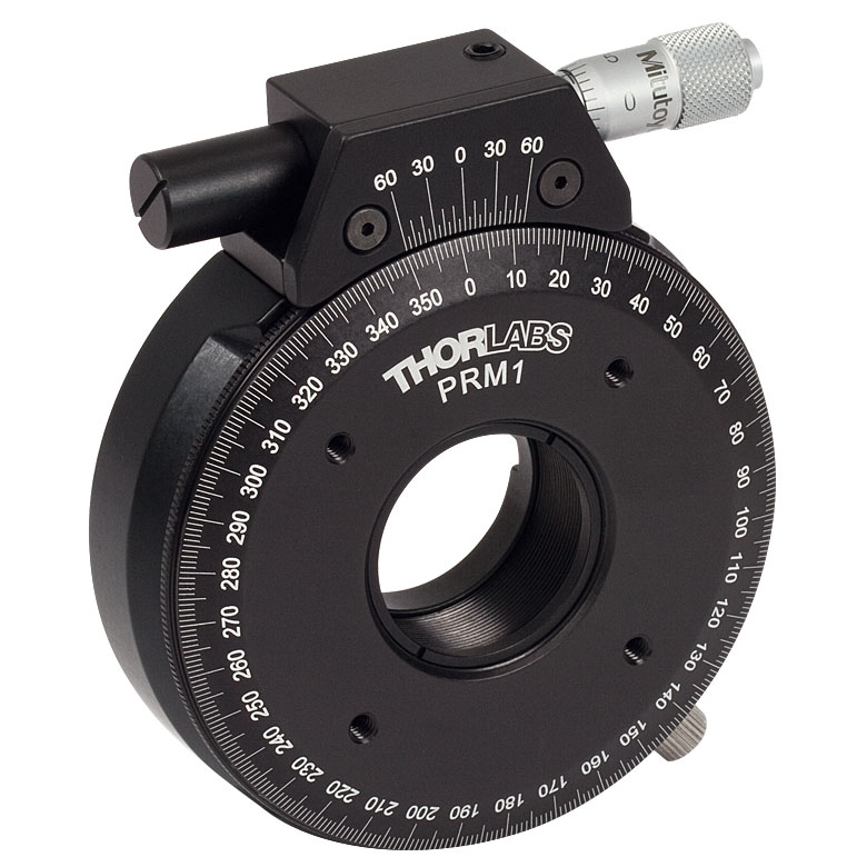 |
| Features | Standard | External SM1 (1.035"-40) Threads | Adjustable Zero | Two Independently Rotating Carriages | Rotates Optic Within Fixed Lens Tube System | Continuous 360° Rotation or 15° Increments | Continuous 360° Rotation or 22.5° Increments | Micrometer |
| Additional Details | ||||||||
| Rotation Mounts for Ø1" Optics | ||||||
|---|---|---|---|---|---|---|
| Item # | LM1-A & LM1-B(/M) | CRM1T(/M) | CRM1LT(/M) | CRM1PT(/M) | KS1RS | K6XS |
| Click Photo to Enlarge | 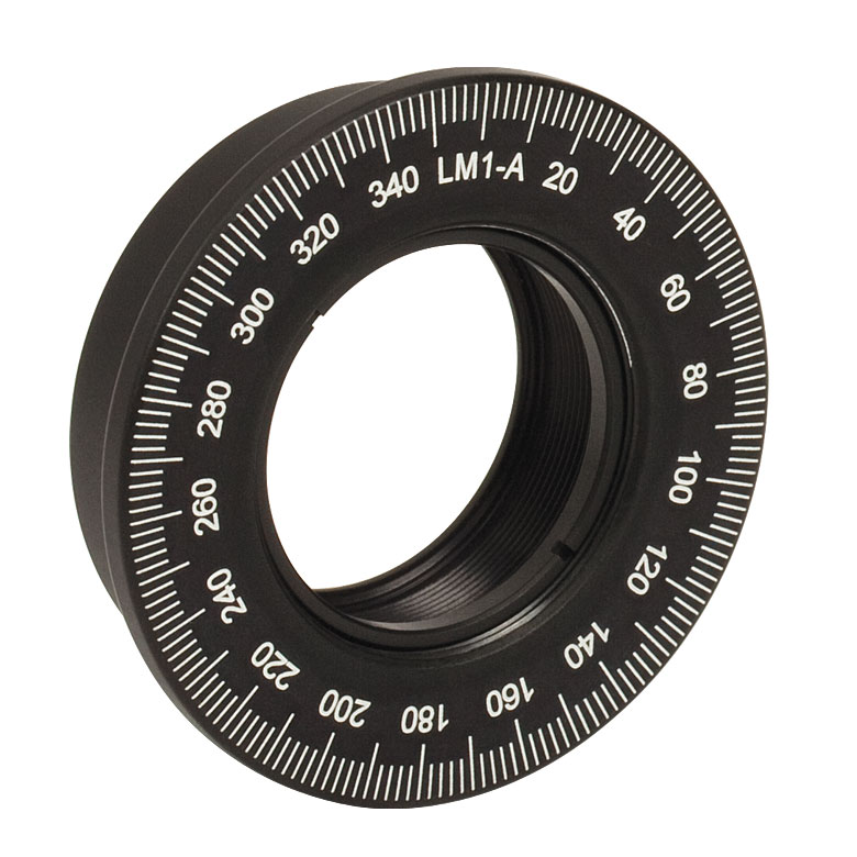 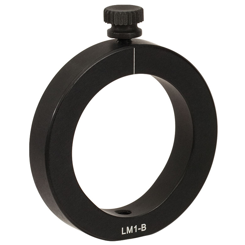 | 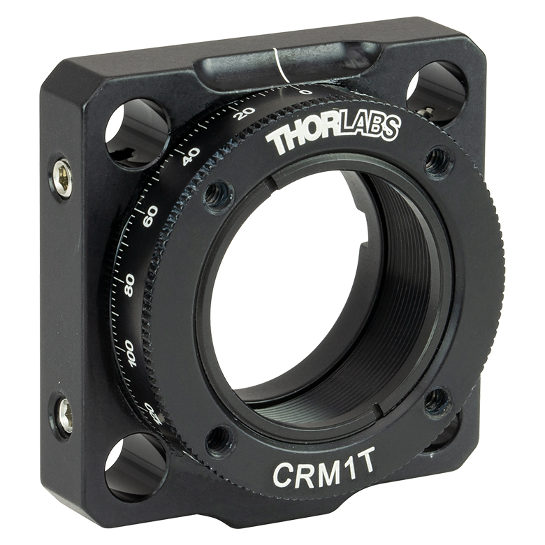 |  |  | 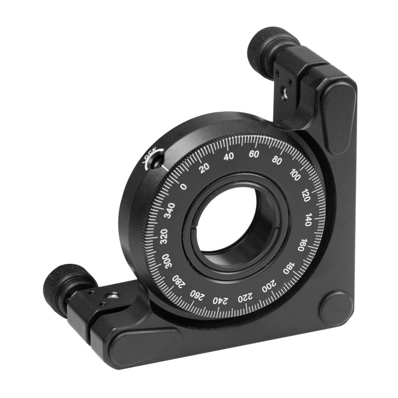 | 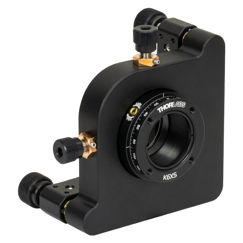 |
| Features | Optic Carriage Rotates Within Mounting Ring | 30 mm Cage-Compatiblea | 30 mm Cage-Compatible for Thick Opticsa | 30 mm Cage-Compatible with Micrometera | ±4° Kinematic Tip/Tilt Adjustment Plus Rotation | Six-Axis Kinematic Mounta |
| Additional Details | ||||||
| Rotation Mounts for Ø2" Optics | |||||||
|---|---|---|---|---|---|---|---|
| Item # | RSP2(/M) | RSP2D(/M) | PRM2(/M) | LM2-A & LM2-B(/M) | LCRM2A(/M) | KS2RS | K6X2 |
| Click Photo to Enlarge | 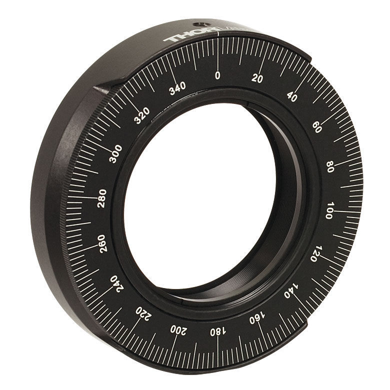 | 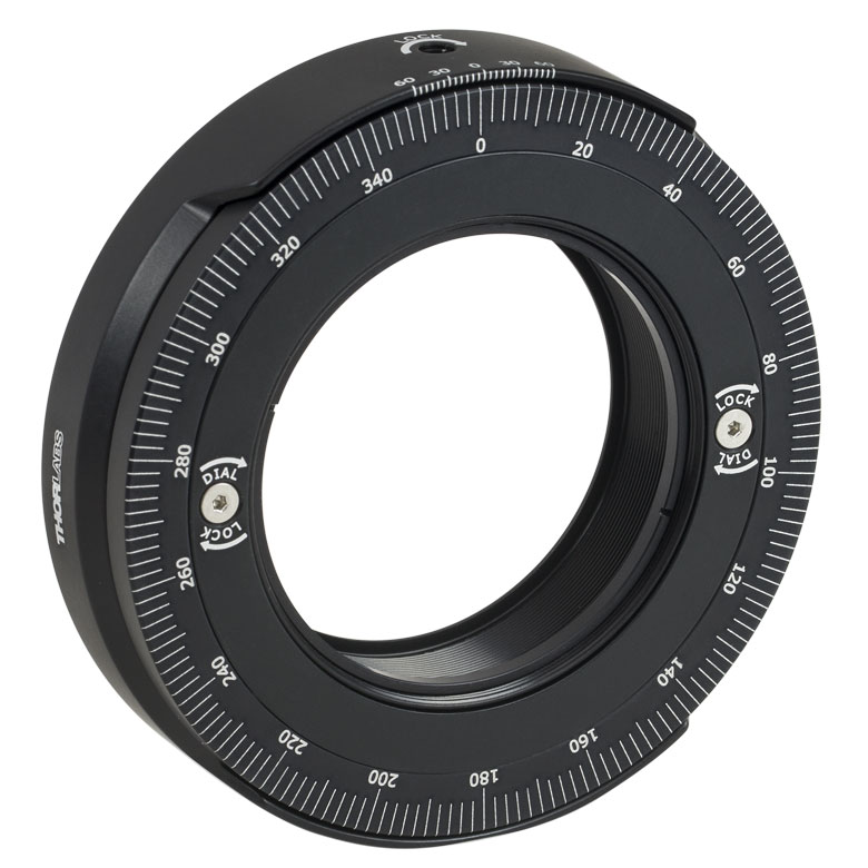 | 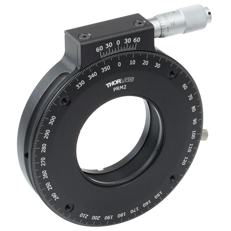 | 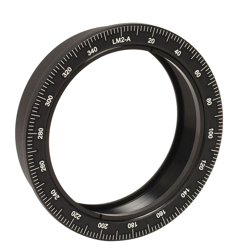 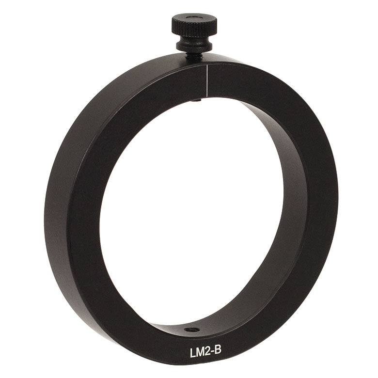 |  |  | 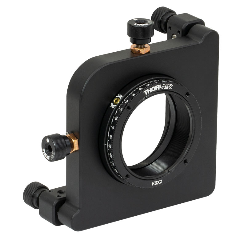 |
| Features | Standard | Adjustable Zero | Micrometer | Optic Carriage Rotates Within Mounting Ring | 60 mm Cage-Compatible | ±4° Kinematic Tip/Tilt Adjustment Plus Rotation | Six-Axis Kinematic Mount |
| Additional Details | |||||||
| Rotation Drive Mechanism and Adjustment Range | Manual, 360° Continuous | Coarse: Manual, 360° Continuous; Fine: ±7° Micrometer | Manual, 360° Continuous | ||||
| Optic Mounting | Internally SM2-Threaded Carriage | Internal SM2 Threads in LM2-A | Internally SM2-Threaded Carriage | ||||
| Maximum Accepted Optic Thickness | 0.51" (13 mm) | 0.54" (13.7 mm) | 0.48" (12.2 mm) | 0.46" (11.7 mm) | 0.52" (13.2 mm) | 0.47" (12 mm) | 0.53" (13.4 mm) |
| Post Mounting | 8-32 (M4) Tap | 8-32 (M4) Tap in LM2-B | 8-32 (M4) Tap | Four Counterbores for 8-32 (M4) Cap Screws | Six Counterbores for 8-32 (M4) Cap Screws | ||
| Cage System Compatibility | N/A | Four 4-40 (M3) Taps on Rotation Dial with 60 mm Spacing | N/A | Four Bores for Ø6 mm Cage Rods with 60 mm Spacing | N/A | N/A | |
手動回転ステージ
| Manual Rotation Stages | ||||||
|---|---|---|---|---|---|---|
| Item # | RP005(/M) | PR005(/M) | MSRP01(/M) | RP01(/M) | RP03(/M) | QRP02(/M) |
| Click Photo to Enlarge | 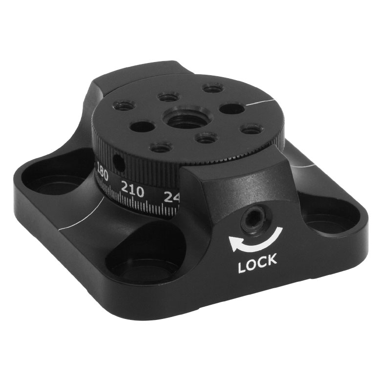 | 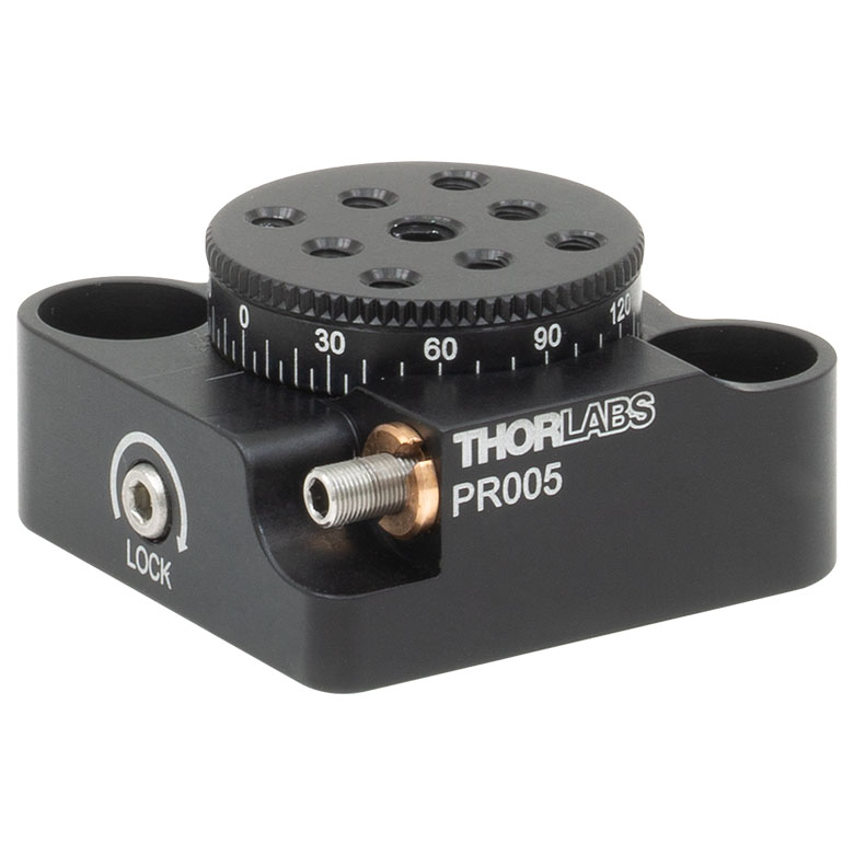 | 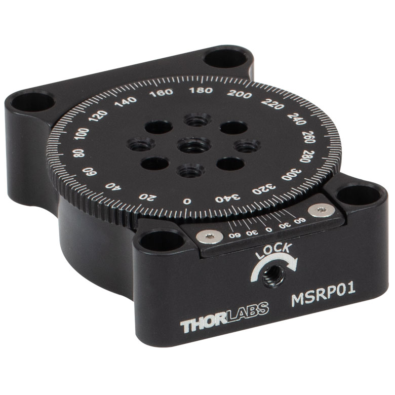 | 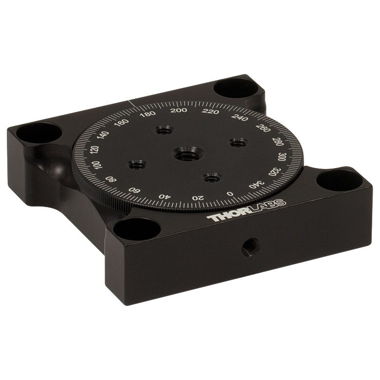 | 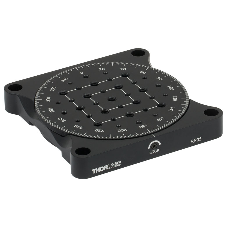 | 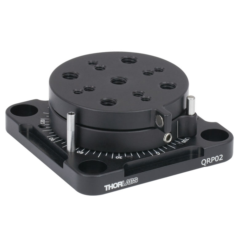 |
| Features | Standard | Two Hard Stops | ||||
| Additional Details | ||||||
| Manual Rotation Stages | ||||||
|---|---|---|---|---|---|---|
| Item # | XRNR1(/M) | XRR1(/M) | PR01(/M) | CR1(/M) | XYR1(/M) | OCT-XYR1(/M) |
| Click Photo to Enlarge | 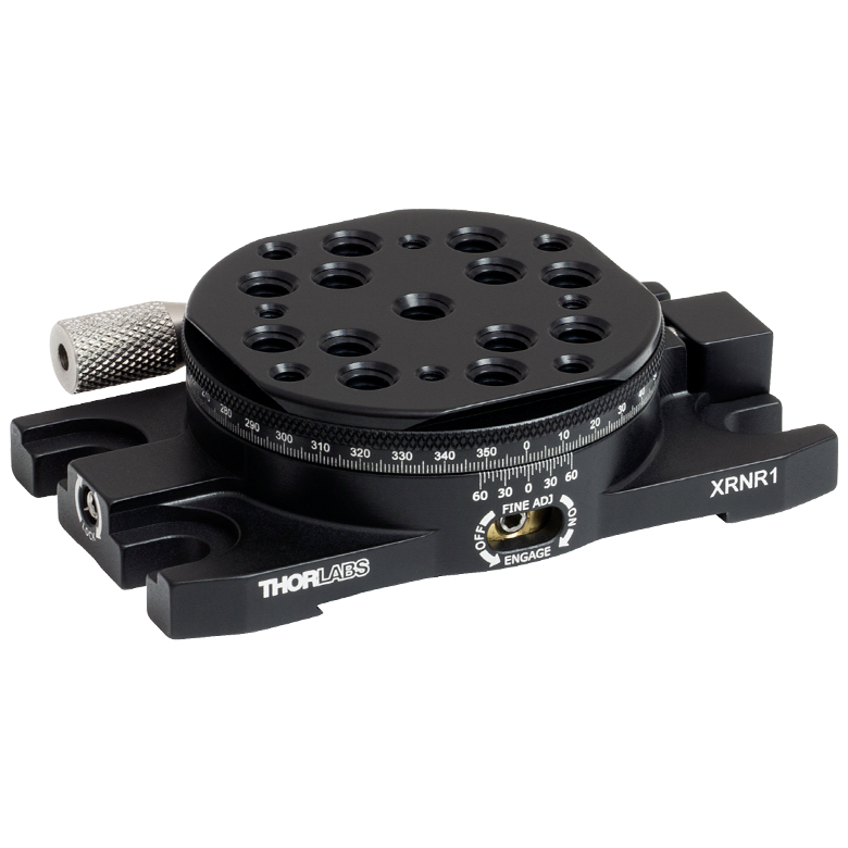 |  | 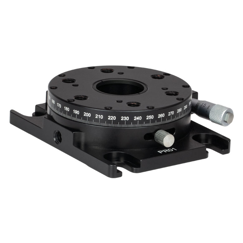 | 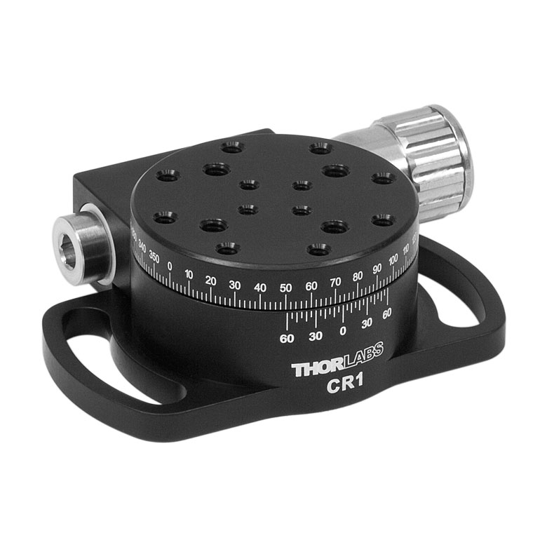 | 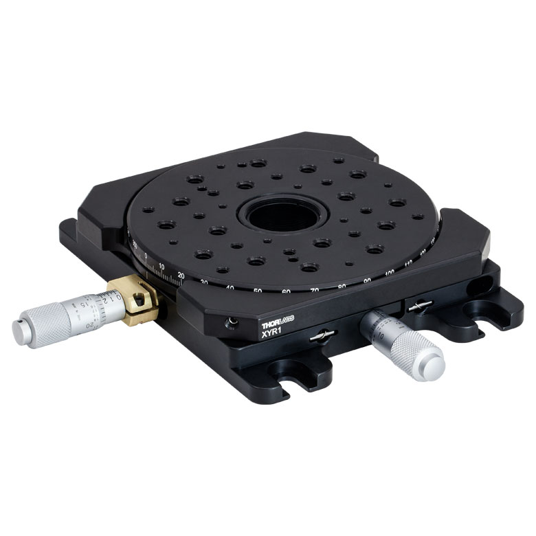 | 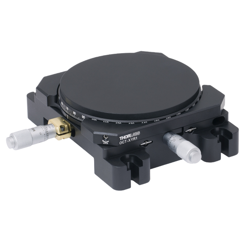 |
| Features | Fine Rotation Adjuster and 2" Wide Dovetail Quick Connect | Fine Rotation Adjuster and 3" Wide Dovetail Quick Connect | Fine Rotation Adjuster and SM1-Threaded Central Aperture | Fine Pitch Worm Gear | Rotation and 1/2" Linear XY Translation | |
| Additional Details | ||||||
電動回転マウント&ステージ
| Motorized Rotation Mounts and Stages with Central Clear Apertures | |||||
|---|---|---|---|---|---|
| Item # | DDR25(/M) | PDR1C(/M) | PDR1(/M) | PDR1V(/M) | PDXR1(/M) |
| Click Photo to Enlarge | 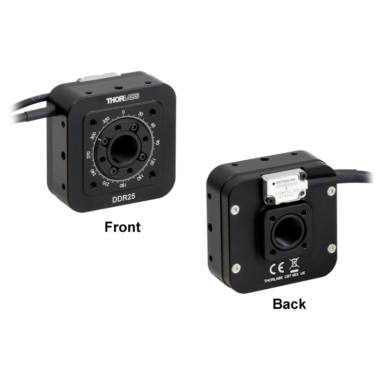 | 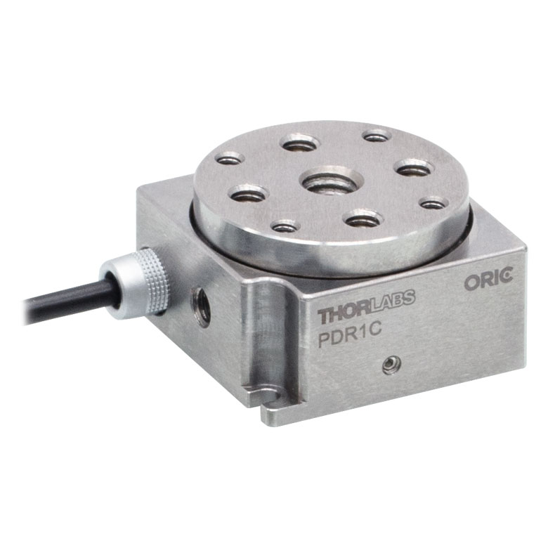 | 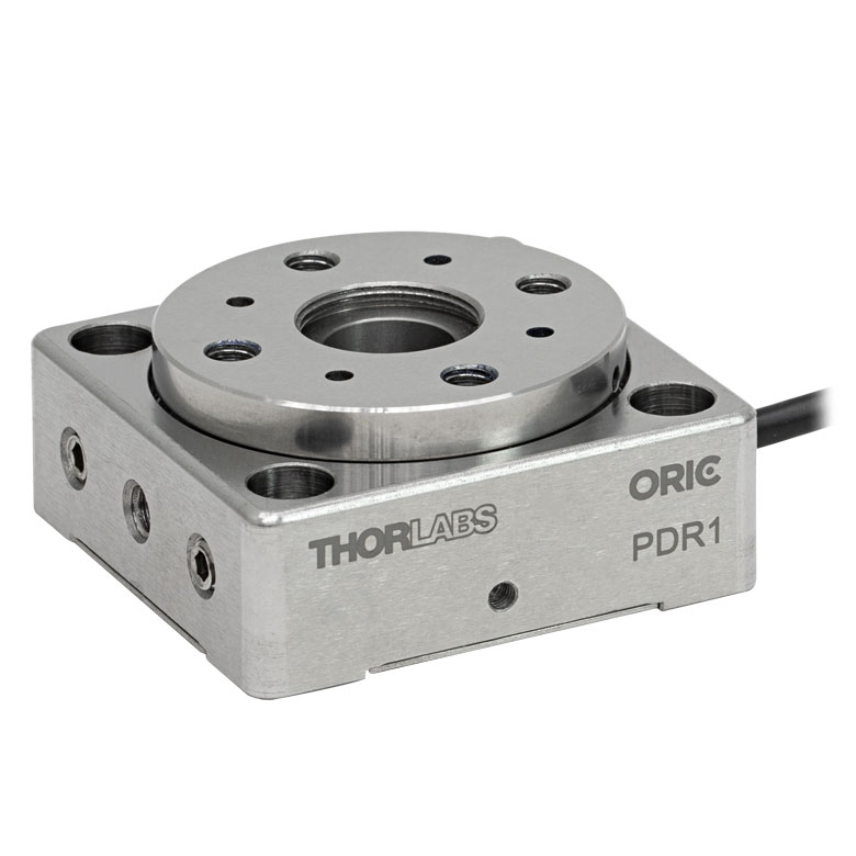 |  |  |
| Features | Compatible with SM05 Lens Tubes, 16 mm Cage System, & 30 mm Cage System | Compatible with 16 mm Cage System | Compatible with SM05 Lens Tubes & 30 mm Cage System | Vacuum-Compatible; Also Compatible with SM05 Lens Tubes & 30 mm Cage System | Compatible with SM05 Lens Tubes & 30 mm Cage System |
| Additional Details | |||||
| Motorized Rotation Mounts and Stages with Central Clear Apertures | |||||
|---|---|---|---|---|---|
| Item # | K10CR1(/M) | PRM1Z8(/M)a | DDR100(/M) | ELL14 | HDR50(/M) |
| Click Photo to Enlarge | 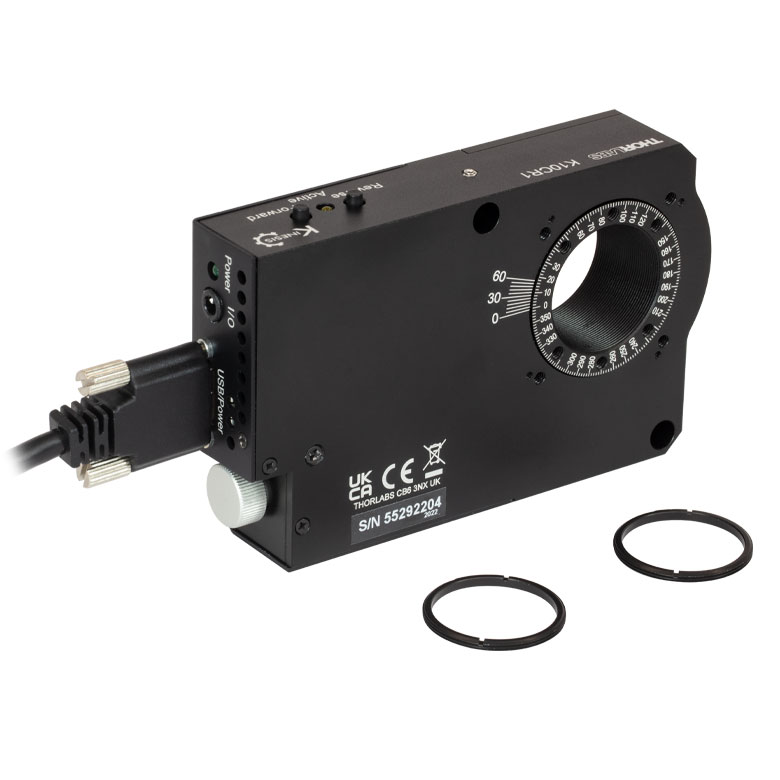 | 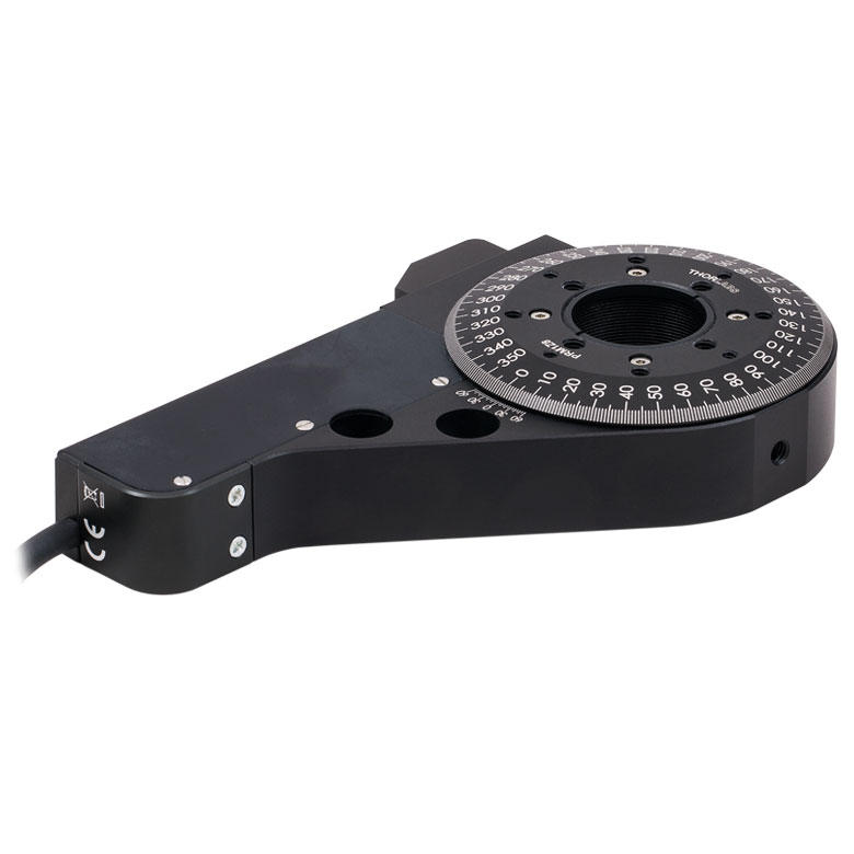 | 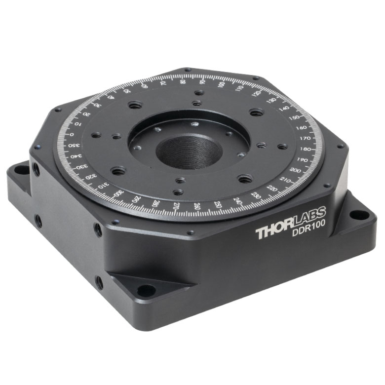 | 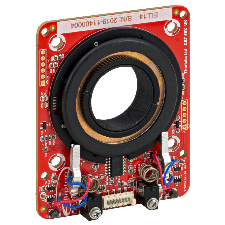 | 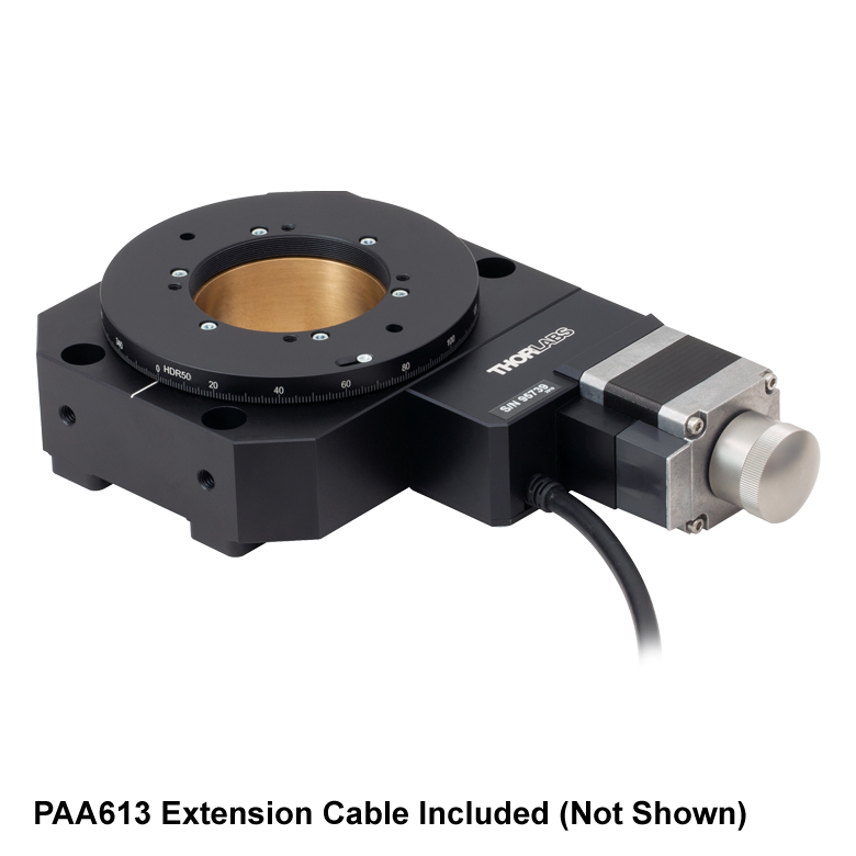 |
| Features | Compatible with SM1 Lens Tubes & 30 mm Cage System | Compatible with SM1 Lens Tubes, 16 mm Cage System, 30 mm Cage System | Compatible with SM1 Lens Tubes, Open Frame Design for OEM Applications | Compatible with SM2 Lens Tubes | |
| Additional Details | |||||
| Motorized Rotation Mounts and Stages with Tapped Platforms | ||
|---|---|---|
| Item # | PRMTZ8(/M)a | ELL18(/M)b |
| Click Photo to Enlarge | 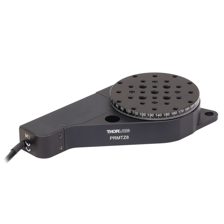 |  |
| Features | Tapped Mounting Platform for Mounting Prisms or Other Optics | Tapped Mounting Platform, Open Frame Design for OEM Applications |
| Additional Details | ||

 ズーム
ズーム
Click to Enlarge
精密回転ステージの概略図
- 360°回転プラットフォーム
- マイクロメータ1目盛につき2.4 arcminの回転
- SM1内ネジ付きの中心穴に厚さ17 mmまでのØ25.4 mm(Ø1インチ)光学素子を取り付け可能
- 耐荷重:11.4 kg(粗調整)、1.7 kg(微調整)
- 固定リングSM1RRが1個付属
回転ステージPR01/Mは高耐荷重で、光学素子や標準的なオプトメカニクス部品、または30 mmケージシステムのセグメントを精密回転させることができます。 回転プラットフォームには、刻印された1°刻みの目盛と、分解能5 arcminのバーニヤ目盛が付いています。
また、垂直面に取り付けられるようM6ザグリ溝と2つのM6タップ穴も付いています。 さらに安定性が必要な場合は、開口部付き直角ブラケットCAM1/Mをご利用いただくことも可能です。

 ズーム
ズーム
Click for Details
PR01A(/M)の取付け穴のパターン
- プリズムやビームスプリッタ、偏光子、その他光学素子用の取付け面
- タップ穴を用いて小型移動ステージやゴニオメータに直接取付け可能
- クランプアーム用に6箇所の取付け位置
- 4個の#4-40キャップスクリュが付属
アダプタープレートPR01A/Mは、4つの#4ザグリ穴を利用して回転ステージPR01/Mの上面に取り付けることができます。小型移動ステージやゴニオステージに直接取り付けられるよう、M2 x 0.4タップ穴が8個と#2-56タップ穴が4個開いています。
また、クランプアームPM3(/M)またはPM4(/M)を使用して光学素子をアダプタの上面に取り付け、PR01(/M)の回転軸に沿って回転させることもできます(ページ上の写真をご参照ください)。 クランプアームの取り付けには、外周に沿って開いている6個のM4タップ穴を利用します。 また、M4タップ穴が4つあるのでステンレススチール製クランプアームPM5/Mともお使いいただけます。

 ズーム
ズーム
Click for Details
Figure 756A 外形図
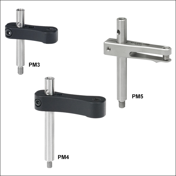
- プラットフォームマウント用のクランプ
- ポストの上部にネジ穴、下部にネジ付きスタッド
- ミリ規格製品はM4 x 0.7ネジ
- 保持できる光学素子の最大高さ:24.6 mm~41.8 mm
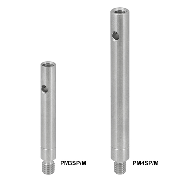
- 保持できる光学素子の高さを高くするためのエクステンションポストもご用意
- PM3SP/M + PM3/M: 高さ56.1 mmまでの光学素子を保持
- PM4SP/M + PM4/M: 高さ91.7 mmまでの光学素子を保持
Click to Enlarge
Figure 756B クランプアーム用エクステンションポスト、ミリ規格は溝付き
クランプアームは、当社のキネマティックプラットフォームマウント、ステージ、およびV字型クランプに光学素子を固定するためのクランプです。PM3/Mは高さ24.6 mmまでの光学素子を保持します。ポストと光学素子固定用のナイロン製先端付き止めネジとの中心間距離は17.5 mmです。PM4/Mは高さ40.9 mmまでの光学素子を保持でき、ポストとナイロン製先端付き止めネジとの中心間距離は29.3 mmです。クランプアームPM3/MおよびPM4/Mで保持できる光学素子の高さは、それぞれに対応するエクステンションポストPM3SP/MおよびPM4SP/Mを接続することで、さらに高くすることが可能です。これらのエクステンションポストは、クランプアームのセットに含まれているポストと同じものです。すべてのクランプアームにはM4 x 0.7ネジが付属します。
クランプアームPM5/Mはすべて熱処理済みのステンレススチールから製造されているため、温度変動を伴う環境中でも安定しており、また真空にも対応しています。このクランプアームはM4 x 0.7タップ穴が1つ以上あるすべてのプラットフォームマウントやステージにお使いいただけますが、特にPOLARIS-K1M4/Mと組み合わせて使用されることをお勧めしています。PM5/Mが保持できる光学素子の高さは最大41.8 mmまでで、ポスト中心から光学素子を保持する接触点までの距離は22.8 mmです。
クランプアームはすべてフレクシャー機構でポストに取付けられますが、その固定には2 mmのボールドライバや六角レンチを使用します。クランプアーム上部の止めネジで光学素子を固定する際も、2 mmのボールドライバまたは六角レンチを使用します。ポストには、ポストを締め付けるときにトルクを加えるために使用する貫通穴も付いています。その他の情報はFigure 756Aをご覧ください。

 ズーム
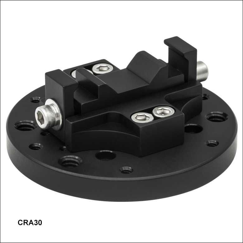
ズーム- 30 mmケージシステムを360°連続回転
- 組立済の30 mmケージシステムを分解せずに取り付け可能
- ネジ1個でクランプの位置をしっかり固定
- 4個の#4-40キャップスクリュが付属
ケージ回転アダプタCRA30/Mは、30 mmケージシステムと回転ステージ PR01/Mを接続し、ステージのマイクロメータを利用してケージシステムを精密にアライメントできます。 このアダプタは、ネジ1個でクランプの位置をしっかり固定できるシステムになっており、30 mmケージシステム内の2本のケージロッドを同時につかむように締め付けることができます。 組立済のケージシステムを開いたクランプ内に置くだけで良いので、ケージロッドをアダプタに通す必要がありません。