 Products Home
超短パルスレーザー用広帯域ビームスプリッター、分散制御
- Deterministic GDD for Femtosecond Laser Pulses
- Designed for P-Polarized Light at 45° AOI
- Infrasil® Windows Available to Balance GDD
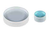
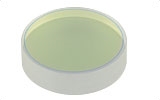
UFBS2080
20:80 Ultrafast Beamsplitter
(600-1500 nm)
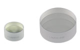
UFBS8020
80:20 Ultrafast Beamsplitter
(600 - 1500 nm)
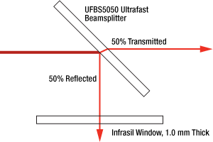
Application Idea
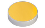
UFBS5050 50:50 Ultrafast Beamsplitter in a
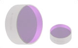
UFBS9010
90:10 Ultrafast Beamsplitter
(600 - 1500 nm)
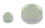
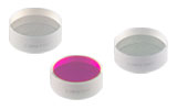
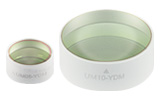
UFBS50502
50:50 Ultrafast Beamsplitter
(1000 - 2000 nm)


Please Wait

特長
- 反射光および透過光ともに確定した群遅延分散(GDD)
- 45°で入射するp偏光用に設計
- 分岐比
- 600~1500 nm用: 20:80、50:50、80:20、90:10 (R:T)
- 1000~2000 nm用: 50:50
- フェムト秒Ti:サファイアレーザおよびYb系レーザに最適化
- UFBS5050のGDDバランスをとるための厚さ1.0 mmのInfrasil(光学石英)ウィンドウ
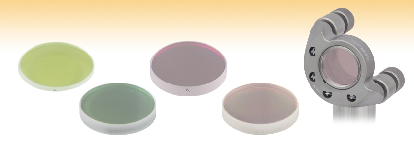
当社では、600~1500 nmの波長範囲では20:80、50:50、80:20、90:10 の4種類の分岐比(R:T)、1000~2000 nmでは50:50 の分岐比(R:T)の超短パルスレーザ用広帯域ビームスプリッタをご用意しています。p偏光を45°で入射して使用するように設計されており、s偏光用ではありません。s偏光や円偏光については、当社のプレート型ビームスプリッタのラインナップをご覧ください。ページ上部の写真に示すように、各超短パルスレーザ用ビームスプリッタにはビームスプリッターコーティング面を指示する矢印が書かれています。目指した性能を得るには、分岐しようとする光をこの面に入射する必要があります。ビームスプリッタの対応する波長範囲は広く、フェムト秒Ti:サファイアパルスレーザやYbやErファイバーレーザに対応します。ビームスプリッタの背面には、ビームスプリッターコーティングと同じ波長範囲での絶対反射率が<0.5%のARコーティングが施されています。Infrasil基板は一種の光学石英ガラスで、溶融石英とほぼ同じ分散性能を持ちますが、1380 nm付近では溶融石英よりも内部透過率が高くなります。
取付け
当社の超短パルスレーザ用ビームスプリッタおよびInfrasilウィンドウの厚さは大変薄いため、標準的な止めネジ(セットスクリュ)方式のマウントには取付けられません。そのため、例えばPolaris®SM1ネジ付きマウントや固定式光学マウントに取り付けることをお勧めします。固定リングは止めネジに比べて光学素子に対する機械的なストレスが小さいため、性能を損なうような光学面の歪みの防止に役立ちます。厚さ4.0 mmのビームスプリッタは当社のPolaris低歪みミラーマウントにも取り付けられます。また、ビームスプリッタはキネマティック接着式ミラーマウントPOLARIS-K1C4 や、接着固定式マウントPOLARIS-B1G内にも取り付け可能です。POLARIS-B1Gは45°の入射角に対して透過開口が最大になるように2ヶ所の切欠きがあるのが特長で、プレート型ビームスプリッタを取付けるのに適しています。
透過ビームと反射ビームのGDDのバランス調整
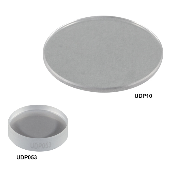
50 fs未満のパルスに超短パルスレーザ用ビームスプリッタUFBS5050をご使用になる際は、GDDのバランスをとるために、反射ビーム内に当社の厚さ1.0 mmのInfrasilウィンドウを入射角0°で1枚挿入することをお勧めします。当社では、厚さ1.0 mmのØ12.7 mm(Ø1/2インチ)およびØ25.4 mm(Ø1インチ)のInfrasilウィンドウをご用意しています(それぞれ型番UDP05およびUDP10)。コーティング無しのウィンドウは、下の表に示すように透過率が平坦な範囲は300 nm~3 µmです。ウィンドウを1枚使用することで、透過アームと反射アームのGDDの差は800 nmにおいて<20 fs2まで低減されます。長いパルスの場合にはスペクトル帯域幅が狭いため、このような分散補償器を追加する必要はありません。詳細については「群遅延」タブをご覧ください。当社のほかの超短パルスレーザ用ビームスプリッタをご使用になる場合は、厚さ1.0 mmのInfrasilウィンドウは厚さが十分ではないため分散を厳密にバランスさせることはできませんが、2つのビーム間の分散のバランスを向上させることは可能です。当社の厚さ4.0 mmのビームスプリッタに厚さ3.0 mm(型番UDP053)または5.0 mm(型番UDP105)のInfrasilウィンドウを使用して、ある程度の分散を補償することができますが、このビームスプリッタ向けに特別に設計されているわけではありません。 その代わりにコーティング無しのUV溶融石英広帯域ウィンドウをご使用いただけます。
当社では、超短パルス用光学素子として700~930 nm、950~1170 nm、1400~1700 nm、および1760~2250 nm用の低GDDミラーをご用意しております。製品のラインナップについては「超短パルス用光学素子」のタブをご覧ください。
50:50超短パルスレーザ用ビームスプリッタの透過ならびに反射アームで平衡な分散を得るための推奨構成(50 fs未満のパルスのみ)
| Item # | GDD in Reflection |
|---|---|
| UFBS2080 | 0.2 mm of Fused Silica |
| UFBS5050 | 0.7 mm of Fused Silica |
| UFBS8020 | 2 mm of Fused Silica |
| UFBS9010 | |GDD| < 150 fs2 (See Note a) |
| UFBS50502 | 0.7 mm of Fused Silica |
50:50超短パルスレーザ用ビームスプリッタにおける群遅延の平衡化
超短パルスレーザ用ビームスプリッタUFBS5050は、フェムト秒レーザーパルスに対して50:50の分岐比をもたらします。また透過アームならびに反射 アームの群遅延分散は共に精度よく確定しており、それらの値はほぼ同一です。 最短パルス(<50 fs)用には、下記でご案内しているように分散補償器を追加することをお勧めします。 なお、Infrasil®と溶融石英の分散はほぼ同じです。
透過アーム
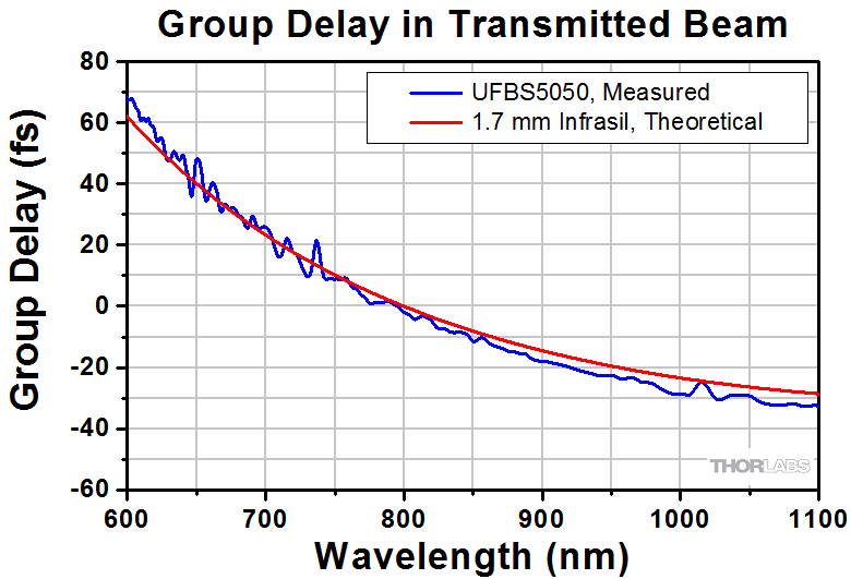
ビームスプリッタUFBS5050を入射角度45°に置いた場合、透過パルスはInfrasil基板内を1.7 mm(基板の厚さは1.5 mmと想定)移動するため、それに伴う分散が発生します。 左下のプロット図は、ビームスプリッタUFBS5050の群遅延測定値と、Infrasilを1.7 mm通過したときの群遅延の計算値の比較です。
反射アーム
ビームスプリッターコーティングは、溶融石英内を0.7 mm移動するときと同じ分散を反射パルスに与えるよう設計されています。 右下のプロット図では、反射アームの群遅延測定値が、溶融石英を0.7 mm移動した場合の群遅延の計算値とほぼ同じであることを示しております。 白色干渉計の限界のため、測定は1100 nmまでとなっております。
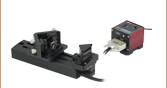
反射アームの分散を透過アームと同じにするため、反射アーム上に 1.0 mmの厚さのInfrasil ウィンドウのいずれか1つを入射角0°で置きます。 配置参考例を右の図にご紹介しています。 このウィンドウにより、反射アームの正味の分散は1.7 mmのInfrailを通過した場合と同じになります。 狭スペクトル帯域幅のパルス(つまり、50 fsよりも長いパルス)では、群遅延分散の変化が遅くなるため、ウィンドウを追加する必要はありません。
Click to Enlarge
透過光の群遅延

Click to Enlarge
反射光の群遅延
フェムト秒パルスレーザ用ならびにピコ秒レーザ用光学素子を幅広くご用意しています。詳細は下表をご参照ください。
| Dielectric Mirror | High-Power Mirrors for Picosecond Lasers | Metallic Mirrors | Low-GDD Pump-Through Mirrors | ||
|---|---|---|---|---|---|
 |  |  |  |  |  |
| Dual-Band Dielectric Mirror, 400 nm and 800 nm | Ytterbium Laser Line Mirrors, 250 nm - 1080 nm | Ultrafast-Enhanced Silver Mirrors, 750 - 1000 nm | Protected Silver Mirrors, 450 nm - 20 µm | Unprotected Gold Mirrors, 800 nm - 20 µm | Pump-Through Mirrors, 1030 - 1080 nm and 940 - 980 nm |
| Deterministic GDD Beamsplitters | Low-GDD Harmonic Beamsplitters | Low-GDD Polarizing Beamsplitters | β-BBO Crystals | Dispersion-Compensating Optics | |
|---|---|---|---|---|---|
 |  |  |  |  |  |
| Beamsplitters & Windows, 600 - 1500 nm or 1000 - 2000 nm | Harmonic Beamsplitters, 400 nm and 800 nm or 500 nm and 1000 nm | High-Power, Broadband, High Extinction Ratio Polarizers, 700 - 1300 nm | β-BBO Crystals for Second Harmonic Generation | Dispersion-Compensating Mirrors, 650 - 1050 nm | Dispersion-Compensating Prisms, 700 - 900 nm |
| Posted Comments: | |
Marco Gaulke
(posted 2024-06-28 15:17:21.553) Dear Thorlabs team,
do you have calculated splitting ratios of this product for (the wrong) s-polarization. I would be interested in that.
Also do you have calculations or data for the angular dependence of the splitting ratio at a fixed wavelength, e.g. 1450 nm?
All the best,
Marco cdolbashian
(posted 2024-07-19 03:54:14.0) Thank you for reaching out to us with this inquiry.
The specced performance, as well as the design goals of this component are dependent on the use of P-polarized light exclusively. These are not characterized or tested with S polarized light. As this is the case, the performance would likely vary from batch-to-batch or unit-to-unit. I have contacted you directly with an example of some test data though we do not have angular dependence of these data. Georgi Yankov
(posted 2024-02-29 08:36:03.77) Hello,
Do you have (Ultrafast Beamsplitter) only 2" and in the tower do you plan to offer those.
I need 90:10, 80:20, 70:30, 60:40, 50:50. 2" in diameter. For wavelengths from 240 to 2600 nm.
Best Regards
George jdelia
(posted 2024-03-01 09:56:56.0) Thank you for contacting Thorlabs. While this is not something we currently offer, I can certainly make note of your request internally so we may look into this in the future. Georgi Yankov
(posted 2024-02-29 08:33:38.347) Hello,
Do you have (Ultrafast Beamsplitter) only 2" and in the tower do you plan to offer those.
I need 90:10, 80:20, 70:30, 60:40, 50:50. 2" in diameter. For wavelengths from 240 to 2600 nm.
Best Regards
George Eugen Nosenko
(posted 2023-11-02 15:01:25.453) How do the UFBS50502 and UFBS8020 work with s-polarized light? Can you provide the correspording reflectivity & dispersion curves? Thanks. cdolbashian
(posted 2023-11-15 03:47:51.0) Thank you for reaching out to us with this inquiry. As we explicitly designed these to work optimally with P-polarized light, we do not have data for the S-polarization. I have reached out to you directly to discuss your application, and a possible alternative. Jonas Kuhl
(posted 2020-10-29 04:53:54.72) Dear Sir or Madam, coming back to the Question asked by mastron in 2015. Is there now an option to get the UFBS9010 in a size of Ø2 or is the coating problem still present?
With kind regards,
Jonas Kuhl. YLohia
(posted 2020-10-29 10:59:50.0) Hello Jonas, we still do not offer a Ø2" version of these beamsplitters due to the same concerns. The coating would severely bend the substrate and would result in a surface flatness of >> 1λ. Xianyu Ao
(posted 2020-08-15 10:08:55.173) Dear Sir/Madam,
Could you please provide the reflection/transmissiton curve of UFBS5050 for s-polarization? BTW, how p-polarization is defined? How to intall UFBS5050, 1 inch diameter, into a 30 mm cage cube? Thanks a lot!
Best,
Xianyu YLohia
(posted 2020-08-18 09:54:27.0) Hello Xianyu, thank you for contacting Thorlabs. I have reached out to you with the s-polarization plots. P-polarized light has its electric field along the plane of incidence. This optic can be mounted into a 30 mm cage cube using the B5CT1 cage cube optic mount. Nils Lenngren
(posted 2020-02-06 12:49:53.98) Dear Sir or Madam,
We need to clean one of our UFBS5050 beamsplitters, and therefore I wonder what material is used for the antireflective coating, in order to find a solvent that will not damage the coating.
Best regards,
Nils Lenngren YLohia
(posted 2020-02-06 04:31:26.0) Hello Nils, thank you for contacting Thorlabs. Unfortunately, we cannot disclose the coating material as the information is proprietary. We would recommend cleaning with isopropyl aclohol using the methods posted here : https://www.thorlabs.com/newgrouppage9.cfm?objectgroup_id=9025 Kurtis Borne
(posted 2019-10-25 15:28:11.503) I am very interested in purchasing the 90:10 ultrafast beamsplitter.
It would be used with a 800 nm, 25 fs beam with a 2 mJ pulse energy (@ 10 kHz).
All the specs seem appropriate, but obviously with these short wavelengths I'm very susceptible to GDD, and I am confused what it means in the provided plot for "reflected GDD." I don't understand the meaning of reporting a GDD for the reflected part of the beam and not the transmitted, and I am worried that the transmitted GDD would be much larger than the acceptable ~25fs^-2 that is reported .
Please let me know if you have any information YLohia
(posted 2019-10-28 03:23:03.0) Thank you for contacting Thorlabs. The transmitted GDD of coatings is usually very small (i.e. < 10 fs^2), which is the case with the UFBS9010. So, the total transmitted GDD is just the material (Infrasil) dispersion. ikb2
(posted 2017-07-12 11:18:10.77) Considering using the beamsplitter/infrasil window combination in an interferometric setup. It seems that if the beams are retroreflected and recombined within the beamsplitter, then the two arms pick up different amounts of dispersion. The reflected beam reflects, passes twice through the infrasil window, then transmits, accumulating 4.4 mm worth of dispersion. The transmitted beam transmits through the beam splitter twice, reflects, and then transmits again, accumulating 5.8 mm worth of dispersion. Do you have a recommendation for working with this setup in the sub-100 fs regime? tfrisch
(posted 2017-09-05 10:45:13.0) Hello, thank you for contacting Thorlabs. It sounds like you are describing a Michelson configuration in which the arm which is reflected, then transmitted, has a different delay than the arm that is transmitted, then reflected. With the compensator plate, the R-R arm and T-T arm can be matched in delay, assuming the retroreflector displaces the beam by more than the beam diameter. A simpler solution might be to use a Mach-Zender configuration. I will reach out to you about this directly. tug13936
(posted 2017-06-13 12:38:56.19) Can you explain why this kind of beam splitter can not work for s-polarization? Can you send me any data for the testing with s-polarization? tfrisch
(posted 2017-06-30 02:56:00.0) Hello, thank you for contacting Thorlabs. The S-state has much worse performance because this was optimized for the P-state. I will reach out to you directly with some typical data. elharel
(posted 2016-12-18 16:51:16.62) Would it be possible to get a 80:20 version? tfrisch
(posted 2016-12-20 02:49:15.0) Hello, thank you for contacting Thorlabs. I will reach out to you directly with details on our custom coating capabilities. m.c.ashby
(posted 2015-12-04 18:17:39.387) Can this beamsplitter be used in reverse to combine two Ultrafast Ti:Sph beams? What is the dependence on polarization? besembeson
(posted 2015-12-07 10:47:21.0) Response from Bweh at Thorlabs USA: Yes you can use this in reverse direction, provided you are familiar with the issues related to phase-sensitivity when coherently combining two beams. If you are hoping to combine one S- and one P-polarized beam (and if the S-reflectivity is acceptable), then I'd suggest using the S-polarized beam in transmission because the dispersion is better behaved. Our UK division will share the S-polarized reflectivity example data with you. sunryu
(posted 2015-06-17 01:55:25.563) It would fit my application. What is the damage threshold? Is this safe for 4 W Ti:Sapphire oscillator output (140 fs, 80 MHz)? jlow
(posted 2015-07-07 10:40:16.0) Response from Jeremy at Thorlabs: We are going to be testing these in the near future and we will post the data to the web when the test is finished. mastron
(posted 2015-05-18 20:09:34.93) It would be nice if the "Low-GDD Ultrafast Beamsplitter for 600 - 1500 nm" and matched Infrasil windows came in Ø2" sizes. Also I'm not sure if I'm missing it somewhere but what is the power damage threshold for these optics? jlow
(posted 2015-07-07 10:35:54.0) Response from Jeremy at Thorlabs: We do not currently have a Ø2" version for these mirrors. The coating would severely bend the substrate and one could expect bad surface flatness so this may not be feasible for some applications. With regard to the damage threshold, we are going to be testing them in the near future and we will post the data to the web when the test is finished. |

 ズーム
ズーム| Item # | UFBS2080 | UFBS5050 | UFBS8020 | UFBS9010 | |
|---|---|---|---|---|---|
| Overall Performance | Rabs = 20 ± 2% Tabs = 80 ± 2% | Rabs = 50 ± 5% Tabs = 50 ± 5% | Rabs = 80 ± 5% Tabs = 20 ± 5% | Rabs = 90 ± 2% Tabs = 10 ± 2% | |
| Wavelength Range | 600 - 1500 nm | ||||
| AR Coating | Rabs < 0.5% over 600 - 1500 nm | ||||
| Diameter | 1" (25.4 mm) | ||||
| Diameter Tolerance | +0.00/-0.10 mm | ||||
| Thickness | 1.5 mm | 4.0 mm | |||
| Thickness Tolerance | ±0.10 mm | ||||
| Clear Aperture | > 80% of Diameter | ||||
| Angle of Incidence (AOI) | 45° | ||||
| Laser-Induced Damage Thresholda | 0.18 J/cm2 (800 nm, 51 fs FWHM, P-Pol, 1000 Pulses) | 0.17 J/cm2 (800 nm, 51 fs FWHM, P-Pol, 1000 Pulses) | - | - | |
| Input Polarization | P Polarization | ||||
| Surface Quality | 15-5 Scratch-Dig | 15-10 Scratch Dig | |||
| Surface Flatness | < λ/5 Over Clear Aperture | < 3λ Over Clear Aperture | < 1λ Over Clear Apertureb | < 1λ Over Clear Aperturec | |
| Parallelism | ≤5 arcmin | ||||
| Substrate | Infrasil® | ||||
| Reflectance/Transmission | 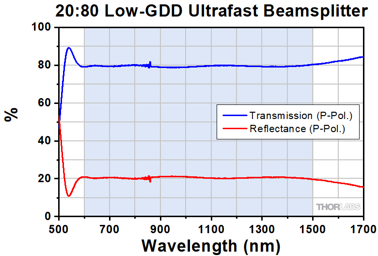 Raw Data |  Raw Data | Raw Data | 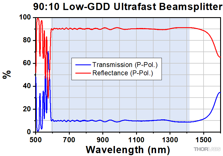 Raw Data | |
| Group Delay (GD) | - | Reflection Raw Data | Transmission Raw Data | Reflection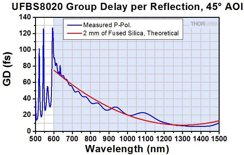 Raw Data | - |
| Group Delay Dispersion (GDD) | - | - | - | - | Reflection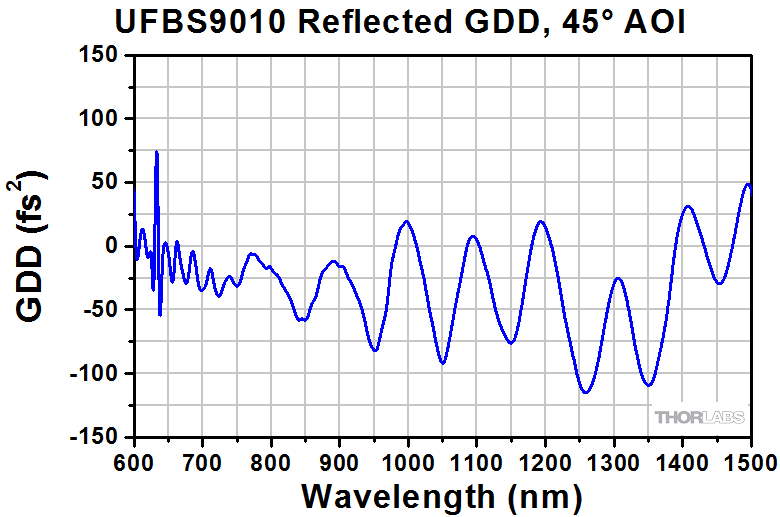 Raw Data |

 ズーム
ズーム| Item # | UFBS50502 | |
|---|---|---|
| Overall Performance | Rabs = 50 ± 5% Tabs = 50 ± 5% | |
| Wavelength Range | 1000 - 2000 nm | |
| AR Coating | Rabs < 0.5% over 1000 - 2000 nm | |
| Diameter | 1" (25.4 mm) | |
| Diameter Tolerance | +0.00/-0.10 mm | |
| Thickness | 4.0 mm | |
| Thickness Tolerance | ±0.10 mm | |
| Clear Aperture | > 80% of Diameter | |
| Angle of Incidence (AOI) | 45° | |
| Laser-Induced Damage Threshold | - | |
| Input Polarization | P Polarization | |
| Surface Quality | 15-10 Scratch-Dig | |
| Surface Flatness | < 2λ Over Clear Aperturea | |
| Parallelism | ≤5 arcmin | |
| Substrate | Infrasil® | |
| Reflectance/Transmission | Raw Data | |
| Group Delay (GD) | Reflection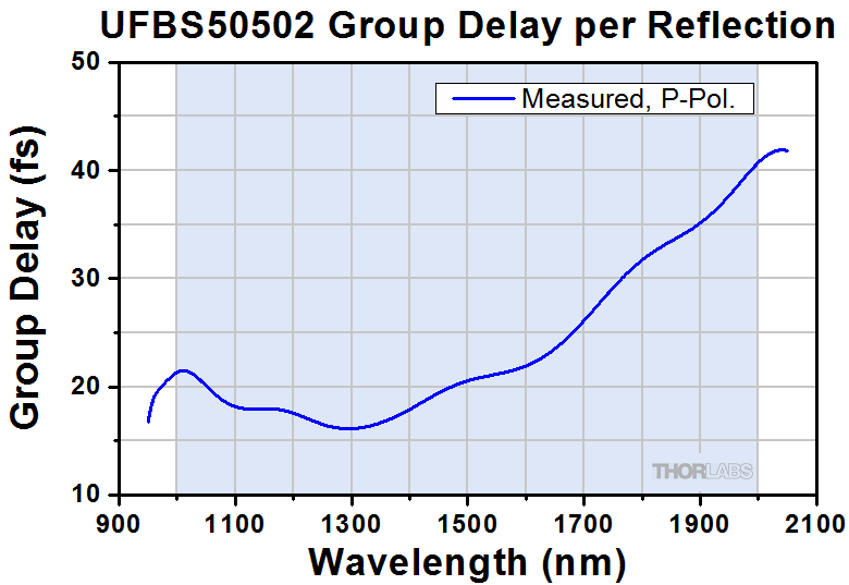 Raw Data | Transmission Raw Data |
ウィンドウ、コーティング無し")
 ズーム
ズーム50:50の超短パルスレーザ用ビームスプリッタの透過ならびに反射ビームで分散のバランスを取るための1.0 mmウィンドウを用いた推奨構成(50 fs未満のパルスのみ)
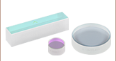
Infrasil (光学石英)ウィンドウは厚さ1.0 mm、3.0 mmと5.0 mmでご用意しております。厚さ1 mmのウィンドウは50 fs未満のパルスレーザにおいてビームスプリッタUFBS5050とともに使用することをお勧めいたします。詳細については「群遅延」タブをご覧ください。
| Item # | UDP05 | UPD053 | UDP10 | UDP105 | |
|---|---|---|---|---|---|
| Diameter | 1/2" (12.7 mm) | 1" (25.4 mm) | |||
| Diameter Tolerance | +0.0 / -0.1 mm | +0.0 / -0.2 mm | +0.0 / -0.1 mm | +0.0 / -0.2 mm | |
| Thickness | 1.0 mm | 3.0 mm | 1.0 mm | 5.0 mm | |
| Thickness Tolerance | ±0.1 mm | ±0.3 mm | ±0.1 mm | ±0.3 mm | |
| Clear Aperture | > 90% of Diameter | ≥ 80% of Diameter | > 80% of Diameter | ≥ 85% of Diameter | |
| Parallelism | < 5 arcmin | < 3 arcmin | < 5 arcmin | < 3 arcmin | |
| Transmitted Wavefront Errora | < λ/10 Over Clear Aperture | ||||
| Surface Quality | 10-5 Scratch-Dig | ||||
| Wavelength Range | 300 nm - 3 µm (Uncoated) | ||||
| Substrate | Infrasil® | ||||
| Transmission Data | Raw Data | Raw Data | Raw Data | Raw Data | |