 Products Home / 自動(電動)ステージ / 電動直線移動ステージ(リニアステージ) / 電動直線移動ステージ(リニアステージ):移動量100 mm以上 / ステッピングモーター直線移動ステージ(リニアステージ)、移動量100 mm
ステッピングモーター直線移動ステージ(リニアステージ)、移動量100 mm

- Stackable in XY, XZ, and XYZ Configurations
- Typical Calibrated On-Axis Accuracy of 2.0 µm
- Horizontal Load Capacity of 20 kg (44 lbs)
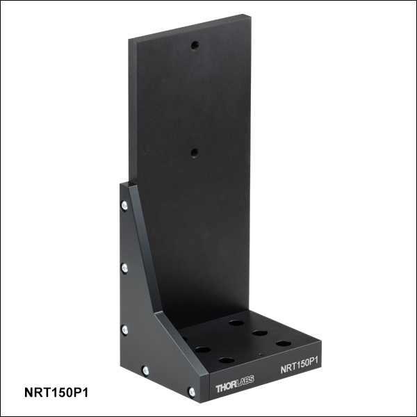
NRT150P1
Right-Angle Bracket
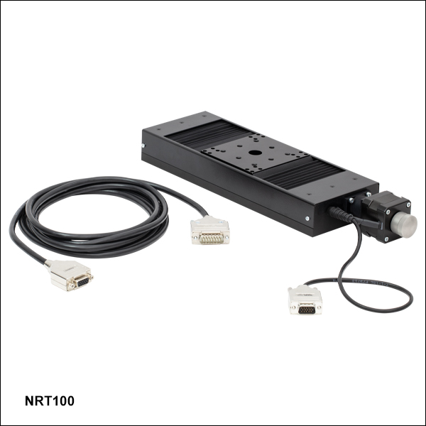
NRT100
100 mm Translation Stage
Application Idea
Two NRT100 Stages
in XZ Configuration,
Using an NRT150P1
Right-Angle Bracket


Please Wait
| Key Specificationsa | |
|---|---|
| Travel Range | 100 mm (3.9") |
| Velocity (Max)b | 30 mm/s |
| Minimum Achievable Incremental Movement | 0.1 µm |
| On-Axis Accuracyc | 2.0 µm (Typical) 5.0 µm (Max) |
| Bidirectional Repeatabilityd | 1 µm |
| Backlashe | < 3 µm |
| Horizontal Load Capacity (Max) | 20 kg (44 lbs) |
| Vertical Load Capacity (Max) | 5 kg (11 lbs) |
| Actuator Type | Stepper Motor |
| Cable Length | 3.0 m (9.8 ft) |
| Recommended Controller | Benchtop Stepper Motor Controllers |
| Motorized Linear Translation Stages | |
|---|---|
| 100 mm | Stepper |
| DC Servo | |
| 150 mm | Stepper |
| Stepper with Integrated Controller | |
| 220 mm | DC Servo |
| 300 mm | Stepper with Integrated Controller |
| DC Servo | |
| 600 mm | DC Servo |
| Optical Delay Line Kits | |
| Other Translation Stages | |
特長
- 最大移動量:100 mm
- 耐荷重
- 水平設置時の荷重:20 kg
- 垂直設置時の荷重:5 kg
- 最高速度:30 mm/s
- 1 µmの双方向再現性
- XY、XZ、XYZに構成可能
- 標準的なオプトメカニクス取付け用M6タップ穴あり
当社の直線移動ステージ(リニアステージ)NRT100/Mは、測定や検査など高耐荷重かつ高分解能が必要な用途向けに最適化されています。 直線移動量は100 mmで、水平に設置した場合の耐荷重は20 kg、垂直に設置した場合は5 kgです。 この自動ステージの典型的な軸確度は、付属の校正ファイルをKinesis®ソフトウェアに使用時2.0 µm(最大5.0 µm)となります。409,600マイクロステップ/回転の2相ステッピングモータによって直接駆動される送りネジは、理論的には100 nm未満の位置分解能でスムーズな移動を実現します。DCサーボモータの移動ステージとは異なり、ステッピングモータ設計では、ステージに電力供給がされていない時にはプラットフォームの位置は固定されます。
メインのプラットフォームは、リニアガイドレールに精密に配列された4つの再循環ボールベアリングで支えられています。 マイクロステップレベルの用途に対して設計されたステッピングモータは、より小さく滑らかな低速移動が可能で、DCサーボモータと比べて大幅に振動雑音が低減されています。 台形送りネジを採用したことにより、従来のアクメネジを使ったステージよりも耐久性が強化され、表面品質が向上したことで摩擦が少なくなり、バックドライブがほとんどないので通常のボールネジで必要となる制動機構が不要というような様々な利点があります。
校正ファイル
リニア移動ステージNRT100/Mは製造時に校正されています。校正を行うと、コントローラがシステム内の機械的エラーを修正できるようになります。送りネジやリンク機構などの機械部品は、一定の許容差をもって製造されます。このような機械的エラーは、指令位置から実際の位置までの誤差をもたらします。しかしこのような誤差量には再現性があるため、Kinesisソフトウェアと付属の校正ファイルを使用すれば補償することが可能です。付属の校正ファイルは、ユーザ入力の位置を必要な機械的モーションに変換します。校正ファイルは型番横の赤いアイコン )
)
校正ファイルの使用は任意ですが、このファイルをインストールしない場合、ステージの典型的な正確度は2.0 µmから15.29 µmに下がります。校正ファイルを使用しなくてもステージの再現性と分解能に影響はありません。
ステージの組合
XY構成をお考えの場合、リニア式位置決めステージNRT100/MやNRT150/M(移動量150 mm)を自由に組み合わせ、ステージのザグリ穴やスロットにM6キャップスクリュを使用して上下に取り付けることができます。 ザグリ穴は可動キャリッジのØ15.0 mm貫通穴からアクセスできます。 XZやXYZ構成には、NRT100/MまたはNRT150/Mを垂直方向に取り付けられる当社の垂直取付用ブラケットNRT150P1/Mがお使いいただけます。
コントローラ(別売り)
こちらの移動量100 mmの移動ステージには1チャンネル、2チャンネル、3チャンネルでご用意している当社のベンチトップ型ステッピングモータ用コントローラが必要です。PCからステージの制御を複雑な設定なしで行うことができます。また、LabVIEW、LabWindows™、ActiveXなどのプログラミングインターフェイスをサポートしています。
移動ステージNRTシリーズには、モータ駆動ケーブルPAA613が各1本付属しています。付属ケーブルの紛失や破損した場合の交換ケーブルも別途ご用意しています(下記参照)。
| Item # | NRT100(/M) |
|---|---|
| Translation | |
| Travel Range | 100 mm (3.9") |
| Bidirectional Repeatabilitya | 1 µm |
| Backlashb | < 3 µm |
| Maximum Velocityc | 30 mm/s |
| Velocity Stability | ±0.1 mm/s |
| Maximum Accelerationc | 30 mm/s2 |
| Minimum Achievable Incremental Movementd | 0.10 µm |
| Minimum Repeatable Incremental Movemente | 2 µm |
| Accuracy | |
| Calibrated Absolute On-Axis Accuracy | 2.0 µm (Typical) 5.0 µm (Max) |
| Maximum Percentage Accuracyf | 0.09% |
| Home Location Accuracy | ±0.6 µm |
| Pitch | < 0.008° (140 µrad) |
| Yaw | < 0.05° (873 µrad) |
| Load Capacity | |
| Horizontal Load Capacity | < 12 kg (26 lbs) (Recommended) 20 kg (44 lbs) (Max) |
| Vertical Load Capacity | < 4 kg (9 lbs) (Recommended) 5 kg (11 lbs) (Max) |
| General | |
| Weight | 2.2 kg (4.9 lbs) |
| Dimensions | 362.7 mm x 100.0 mm x 43.5 mm (14.28" x 3.94" x 1.71") |
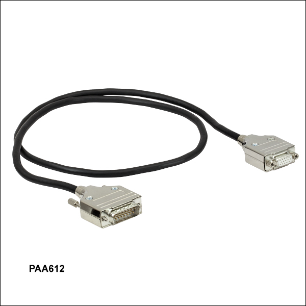
ステッピングモータ用駆動ケーブルPAA612ならびにPAA613
DA15オス型-DE15メス型
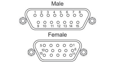
| DA15 Male Pin | DE15 Female Pin | Description |
|---|---|---|
| 11 and 12 | 1 | Limit Switch Ground |
| 10 | 2 | Forward Limit Switch |
| 9 | 3 | Reverse Limit Switch |
| 7 | 4 | Motor Phase B -ve |
| 14 | 5 | Motor Phase B +ve |
| 8 | 6 | Motor Phase A -ve |
| 15 | 7 | Motor Phase A +ve |
| 6 | 9 | Not Connected |
| 5 | 13 | Limit Switch +5 V |
モータ
Dタイプオス型
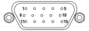
| Pin | Designation | Pin | Designation |
|---|---|---|---|
| 1 | Limit Switch Ground | 9 | Not Connected |
| 2 | Forward Limit Switch | 10 | Not Connected |
| 3 | Reverse Limit Switch | 11 | Not Connected |
| 4 | Motor Phase B -ve | 12 | Not Connected |
| 5 | Motor Phase B +ve | 13 | Limit Switch +5 V |
| 6 | Motor Phase A -ve | 14 | Not Connected |
| 7 | Motor Phase A +ve | 15 | Ground/Earth |
| 8 | Not Connected |
ソフトウェア
Kinesisバージョン1.14.52
このKinesisソフトウェアパッケージには、当社のKinesisシステムコントローラを制御するためのGUIが含まれています。
下記もご用意しております。
- 通信プロトコル

Figure 58A KinesisソフトウェアのGUI画面
当社のKinesisソフトウェアパッケージを用いて、当社の様々なモーションコントローラを駆動することができます。このソフトウェアは小型で低出力のシングルチャンネルドライバ(K-Cube®など)から、高出力でマルチチャンネルのベンチトップ型ユニットやモジュール型の19インチラックナノポジショニングシステム(ラックシステムMMR60x)まで、当社Kinesisシリーズの様々なモーションコントローラの制御用にご使用いただけます。
Kinesisソフトウェアでは.NETコントロールを使用できるため、最新のC#、Visual Basic、LabVIEW™、あるいはその他の.NET対応言語を使用してカスタムプログラムを作成することができます。.NETフレームワークの使用を想定していないアプリケーションのために、ローレベルのDLLライブラリも含まれています。中央シーケンスマネージャ(Central Sequence Manager)は、当社のすべてのモーションコントロール用ハードウェアの統合と同期の機能をサポートしています。
この共通のソフトウェアプラットフォームにより、ユーザは単一のソフトウェアツールを習得するだけで、あらゆるモーションコントロールデバイスを1つのアプリケーション内で組み合わせて使用することができます。このように1軸システム用から多軸システム用までのあらゆるコントローラを組み合わせ、それら全てを1台のPCの統合されたソフトウェアインターフェイスから制御できます。
このソフトウェアパッケージには2つの使い方があります。1つはGUI(グラフィカルユーザーインターフェイス)ユーティリティを用いる方法で、コントローラの到着後すぐに直接的な操作と制御を行なうことができます。もう1つは一連のプログラミングインターフェイスを用いる方法で、ご希望の開発言語によりカスタム仕様の位置決めやアライメント用のプログラムを簡単に作成することができます。
Kinesisソフトウェアでは新しい.NETコントロールが使用でき、最新の最新のC#, Visual Basic, LabVIEW™、ほかの.NET対応言語を使用する開発者がカスタムにプログラムを作成することもできます。
C#
このプログラミング言語はマルチプログラミングパラダイムやマルチプログラミング言語が使用可能となるよう設計されているため、複雑な問題が簡単かつ効率的に解決できます。型付け、命令型、宣言型、関数型、ジェネリック、オブジェクト指向、そしてコンポーネント指向が含まれます。 この共通のソフトウェアプラットフォームにより、1セットのソフトウェアツールを習得するだけで、あらゆるKinesisコントローラを簡単に組み合わせることができます。このようにして1軸システムのコントローラから多軸システムのコントローラまで、様々なコントローラを組み合わせ、全てを1台のPCのソフトウェアインターフェイスから制御することが可能となりました。
Kinesisシステムソフトウェアを使用するには2つの手段があります。コントローラを直接つないで制御を行なう付属のGUI(グラフィカルユーザーインターフェイス)ユーティリティ、またはご希望の開発言語でカスタム仕様の位置決めやアライメントを簡単にプログラムできる一連のプログラミングインターフェイスです。
Kinesisモーションコントロールライブラリの構築の参考となる実行可能なプロジェクト機能拡張例については下のリンクをクリックしてください。なお、Quick Startのプロジェクト例の実行には別の統合開発環境(IDE)(Microsoft Visual Studioなど)が必要です。C#のプロジェクト例はKinesisソフトウェアパッケージに付属する.NETコントロールで実行可能です(詳細は「Kinesisソフトウェア」タブをご覧ください)。
 | Click Here for the Kinesis with C# Quick Start Guide Click Here for C# Example Projects Click Here for Quick Start Device Control Examples | |
LabVIEW
LabVIEWは、.Netコントロールを介してKinesisベースのコントローラとの通信に使用できます。LabVIEWでは、ツールとオブジェクトでフロントパネルとして知られるユーザーインターフェイスを構築した後、グラフィカル表記の関数を使ってコードを追加し、フロントパネルのオブジェクトを制御します。下記のLabVIEWチュートリアルでは.Netコントロールを使用してLabVIEW内Kinesis駆動デバイス用の制御GUIを作成するための情報をご提供しています。 LabVIEWでコントローラを制御する基本的な方法や、LabVIEW GUIを用いてデバイスを操作する前に行うべき設定の手順についても解説しています。
 | Click Here to View the LabVIEW Guide Click Here to View the Kinesis with LabVIEW Overview Page | |
| Posted Comments: | |
user
(posted 2023-09-06 16:18:51.547) Hello,
i wonder if this stage is compatible with the new KST201 K-Cube controller.
Thank you very much fguzman
(posted 2023-09-08 05:26:20.0) Thanks for your enquiry. The 100 mm Linear Translation Stage, Stepper Motor needs the BSC controller https://www.thorlabs.com/newgrouppage9.cfm?objectgroup_id=1704 If you have any other enquiries please contact Europe@thorlabs.com Andy Nave
(posted 2022-08-25 09:53:43.39) Hi,
I think there is a problem with the APT software as it seems it cannot initialise properly while a file is being read or written to.
I have a python script which is continuously reading a file and only when it is turned on the APT software cannot find the stage connected to the computer.
However, if I first start the APT software and then turn on the python script everything is fine.
Could you solve this issue?
Thanks DJayasuriya
(posted 2022-08-25 09:55:26.0) Thank you for your inquiry, This may depend on the file that your reading and the your script opens a connection to the device. We have got in touch with you directly to resolve the issue. Thomas Panier
(posted 2022-03-30 14:53:44.883) Hi, is it possible to control this stage with a K-Cube™ Stepper Motor Controller? Thanks. cwright
(posted 2022-04-01 05:26:11.0) Response from Charles at Thorlabs: Thank you for your query. The NRT100 requires the benchtop range of controllers due to the high current requirement of the stage and they cannot be used with the KST101 controllers. Xi Tang
(posted 2021-08-12 17:13:11.31) Dear Thorlabs,I prefer to know what's kind of your product' s operation temperatures range is -20℃ to 60℃ and 20mm to 200mm's travel range fulfill our requirements. If your company have such kinds of product, can you sent the specification of this product to my e-mail. DJayasuriya
(posted 2021-08-17 06:12:07.0) thank you for your inquiry. We will get in touch with you directly to discuss your application. user
(posted 2021-06-14 17:37:31.44) Dear Thorlabs,
Hello, I would like to control NRT100/M stage and BSC202 by Python.
So, could you please send me example codes?
Thanks!! cwright
(posted 2021-06-15 05:41:01.0) Response from Charles at Thorlabs: Hello and thank you for your query. While we do not officially support python we do have an example we can provide as a courtesy. There are a few ways you can use Python with our controllers. You would be able to use Kinesis’ .NET API via the clr module (if you're using IronPython) or Kinesis’s C API via the ctypes module(if you're using CPython). The DLLs required are located in the installation directory. Alternatively, as our devices use an FTDI chip to communicate with a host PC over USB, you can use serial commands via the pySerial module. The requisite commands and serial parameters can be found in our communications protocol - https://www.thorlabs.com/Software/Motion%20Control/APT_Communications_Protocol.pdf Andrew Allan
(posted 2020-11-18 06:30:22.127) Is the NRT100 supported through the ThorlabsAPTStage Micromanager driver? cwright
(posted 2020-11-19 09:16:38.0) Response from Charles at Thorlabs: Hello Andrew and thank you for your query. Unfortunately the NRT100 is not supported by Micromanager at this time. Please note that this is third party software so Thorlabs cannot add this support. akuznetsov
(posted 2018-07-03 20:13:29.4) The entire Thorlabs selection of motion controllers using APT and Kinesis software does not fit the constraints of a lab where automation equipment must be OS agnostic. For specific stations, and as a general practice, we obtain equipment such that we could automate it with Windows and macOS, RS-232 interface has been very helpful with this task. When testing DUT which are OS specific, the automated equipment must be controlled under the same OS as the DUT, otherwise it's not automated anymore. I've brought up this issue with Thorlabs for almost a year now and there's still no progress. rmiron
(posted 2018-07-11 06:20:04.0) Response from Radu at Thorlabs: Thank you for your feedback. It might not look like it, but the fact that customers such as yourself raise this issue repeatedly helps with pushing our development process in the right direction. This year we have in fact commenced work on translating our current .NET API into cross-platform .NET Core libraries. Unfortunately, because our resources are quite limited, progress is slow. Consequently, I don't expect the new API to be released until 2019. mohatiti341
(posted 2018-02-22 08:35:43.14) Is there any guide showing the control of benchtop stepper motor with LabVIEW ? rmiron
(posted 2018-02-26 11:57:29.0) Response from Radu at Thorlabs: There are two possible routes to controlling our stepper motor-driven devices via LabVIEW. One would be via the ActiveX controls supplied with our APT software. You can find a guide, along with plenty of examples, on this website under "Services"->"Downloads"->"Motion Controllers"->"APT with LabVIEW". In the installation path of APT you will also find a file named "APT Server Help" which is the documentation of the ActiveX-based API.
Alternatively, you can use the .NET controls supplied with our Kinesis software. Analogously to APT, under "Services"->"Downloads"->"Motion Controllers"->"Kinesis" you can find a guide for how to use those controls in LabVIEW. The documentation of this API can be found in the installation path of Kinesis under the name "Thorlabs.MotionControl.DotNet_API". Unfortunately, we lack example VIs for the .NET controls, but we are planning to add some in the coming year. user
(posted 2015-12-10 17:18:14.94) Is there a specification for the maximum torque which can be applied to the stage (for off-center loads which are not applied during motion)? bhallewell
(posted 2015-12-14 03:22:33.0) Response from Ben at Thorlabs: Thank you for your question here. We currently don't list a specification for off-axis torque loads for our motion control devices. I will contact you directly to discuss the performance of this stage within your application. jonathan
(posted 2013-03-20 15:24:29.213) The documentation under pin diagram uses a reverse numbering scheme than connectors have printed on them. Thorlabs defines the top RIGHT pin of a DB-15 HD cable to be pin 1. Even though the actual connector on the stage has a little "1" printed next to the pin that Thorlabs says in their documentation is pin "5".
Be VERY careful if you try to interface this with a third party motion controller, as you will end up connecting everything incorrectly. lmorgus
(posted 2013-03-21 08:30:46.77) A response from Laurie at Thorlabs to jonathan: Thank you for taking the time to point out an error on our website. You are correct that the pin diagram on our website was in error. We apologize for the frustration this likely caused. We have updated our documentation, both on the web under the "Pin Diagram" tab as well as the manual attached to our website to correct the error and prevent future confusion. jjurado
(posted 2011-08-29 11:02:00.0) Response from Javier at Thorlabs to sameera.atragji: Thank you for contacting us. We developed an interface, called the APT software, which is built on an ActiveX plaftorm, allowing for easy integration into the LabVIEW environment. We provide documentation in the form of video tutorials, a help file, sample vi's and an extensive pdf document to guide you in the process of controlling the stages through LabVIEW. The recommended controller for the NRT stepper motor stages is the BSC10x controller. Please visit the link below for links to the documentation mentioned above:
http://www.thorlabs.com/NewGroupPage9.cfm?ObjectGroup_ID=1704 (See Software and APT Tutorials tabs) sameera.atraqji
(posted 2011-08-29 05:38:08.0) Hello,
How can I use travel stage with labview.
Best regards,
Sameera |
電動リニアステージ
電動の直線移動ステージとしては、ピエゾ駆動の20 µm移動ステージからダイレクトドライブ方式の600 mm移動ステージまで、様々な最大移動量の製品をご用意しております。ステージの多くは、それらを用いてXY軸やXYZ軸などの多軸ステージを構築することができます。ファイバ結合用としては、多軸ステージのページをご覧ください。標準の電動ステージを用いるよりも精密な調整が可能です。直線移動ステージのほかに、電動の回転ステージおよびゴニオステージもご用意しております。また手動移動ステージもございます。
ピエゾステージ
これらのステージでは、様々な駆動機構にピエゾ素子が組み込まれています。ステージORIC®シリーズでは、「スティック-スリップ」と呼ばれる摩擦特性を利用したピエゾ慣性アクチュエータが用いられており、それにより長い移動距離が得られています。当社のモジュール式クイック接続型移動ステージXR25シリーズは、同じ原理で動作するピエゾ慣性アクチュエータPIA25で駆動できます。移動ステージNanoflex™シリーズは、手動アクチュエータに加えて標準的なピエゾアクチュエータが用いられています。ステージElliptec®シリーズでは共振ピエゾモータが用いられており、共振に伴うモータ先端の楕円形の動きで可動プラットフォームを押したり引いたりします。Z軸ステージLPS710E/Mにはピエゾ移動に対する機械的な増幅機構が組み込まれており、またそれに適したコントローラが付属しています。
| Piezoelectric Stages | ||||
|---|---|---|---|---|
| Product Family | ORIC® PDXZ1 Closed-Loop 4.5 mm Vertical Stage | ORIC® PD2 Open-Loop 5 mm Stage | ORIC® PDX2 Closed-Loop 5 mm Stage | ORIC® PDX4 Closed-Loop 12 mm Stage |
| Click Photo to Enlarge | 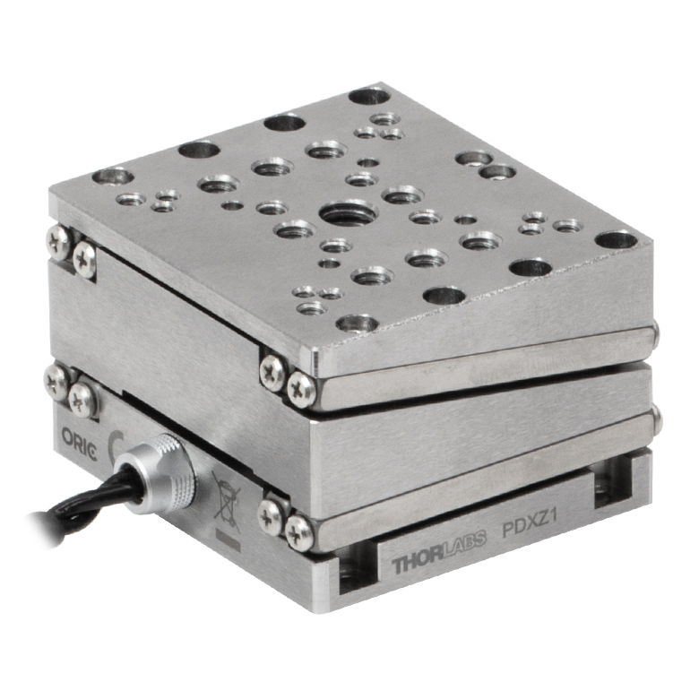 |  |  | 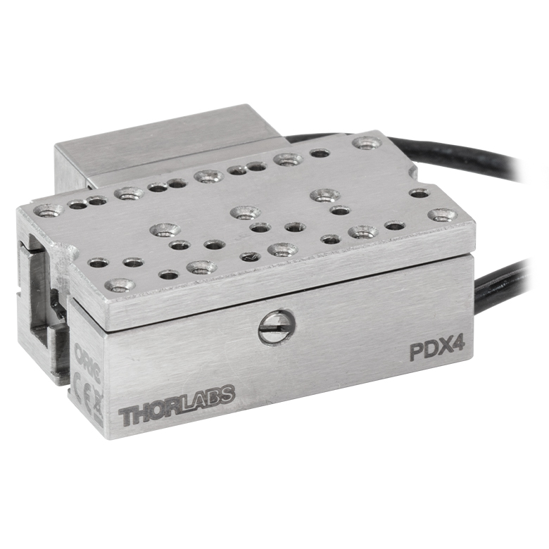 |
| Travel | 4.5 mm | 5 mm | 12 mm | |
| Speed | 1 mm/s (Typ.)a | 10 mm/s (Typ. Max)b | 8 mm/s (Typ.)c | 15 mm/s (Typ.)a |
| Drive Type | Piezoelectric Inertia Drive | |||
| Possible Axis Configurations | Z | X, XY, XYZ | ||
| Mounting Surface Size | 45.0 mm x 42.0 mm | 13.0 mm x 13.0 mm | 13.0 mm x 23.0 mm | |
| Additional Details | ||||
| Piezoelectric Stages | |||||||
|---|---|---|---|---|---|---|---|
| Product Family | ORIC® PD1 Open-Loop 20 mm Stage | ORIC® PD1D Open-Loop 20 mm Monolithic XY Stage | ORIC® PDX1 Closed-Loop 20 mm Stage | ORIC® PD3 Open-Loop 50 mm Stage | Compact Modular XRN25X 25 mm Stage | Modular XR25X 25 mm Stage | |
| Click Photo to Enlarge | 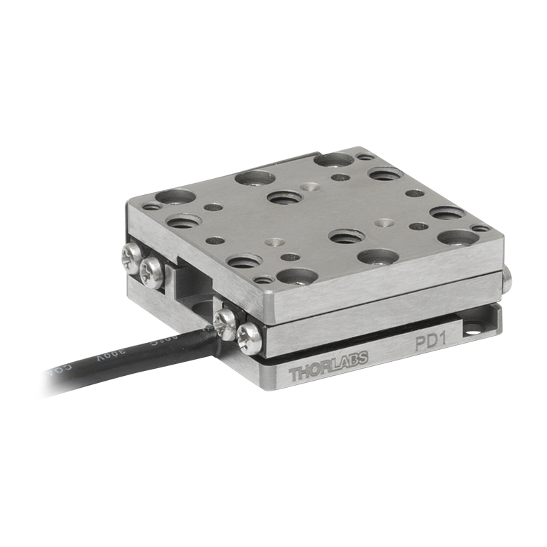 | 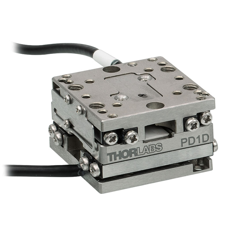 | 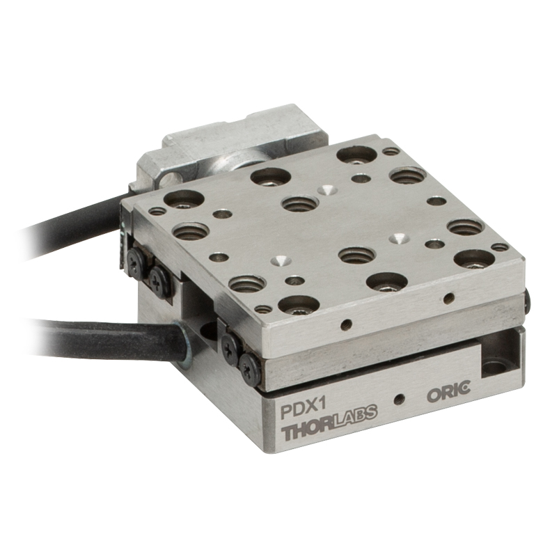 |  |  |  | |
| Travel | 20 mm | 50 mm | 25 mm | ||||
| Speed | 3 mm/s (Typ. Max)a | 20 mm/s (Typ. Max)b | 10 mm/sc | ≤3.6 mm/mind | ≤3.6 mm/mind | ||
| Drive Type | Piezoelectric Inertia Drive | ||||||
| Possible Axis Configurations | X, XY, XYZ | XY, XYZ | X, XY, XYZ | X, XY, XYZ | X, XY, YZ, XZ, XYZ | ||
| Mounting Surface Size | 30.0 mm x 30.0 mm | 80.0 mm x 30.0 mm | 85.0 mm x 50.7 mm | 110.0 mm x 75.7 mm | |||
| Additional Details | |||||||
| Piezoelectric Stages | ||||||
|---|---|---|---|---|---|---|
| Product Family | Nanoflex™ 20 µm Stage with 5 mm Actuator | Nanoflex™ 25 µm Stage with 1.5 mm Actuator | Elliptec® 28 mm Stage | Elliptec® 60 mm Stage | LPS710E 1.1 mm Vertical Stage | |
| Click Photo to Enlarge | 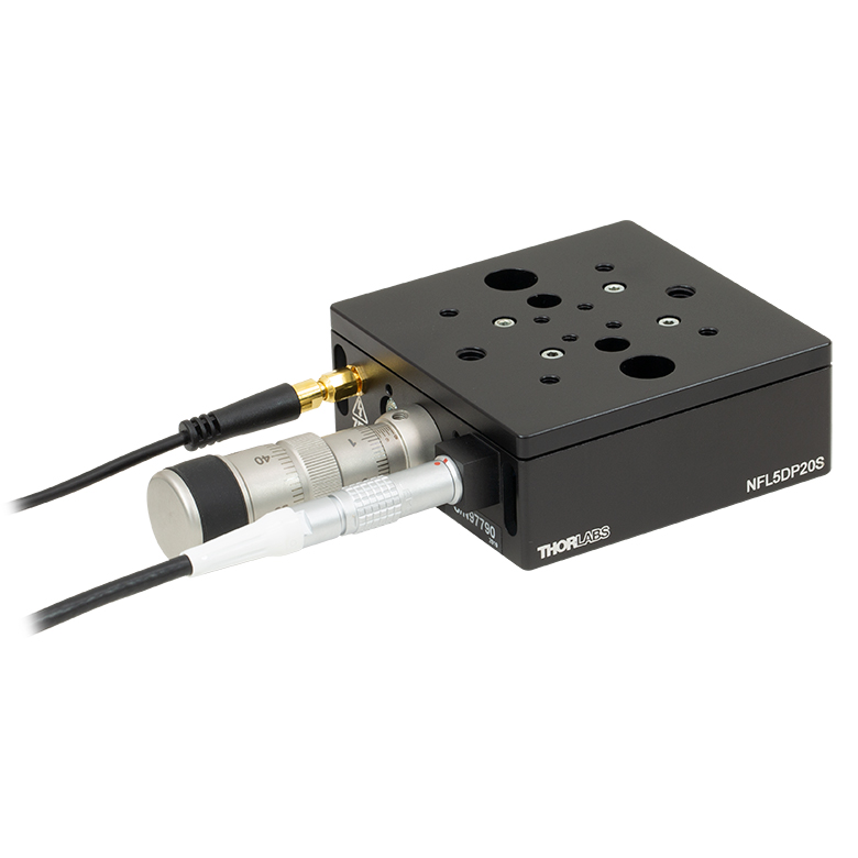 | 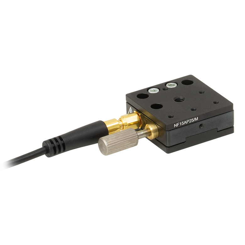 | 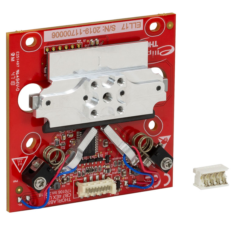 | 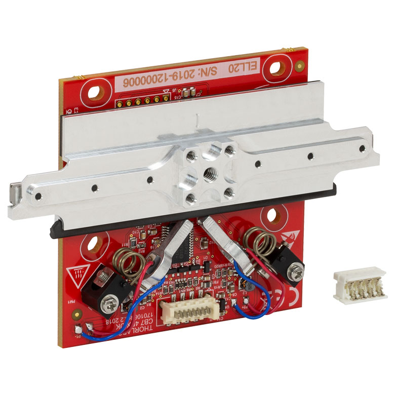 | 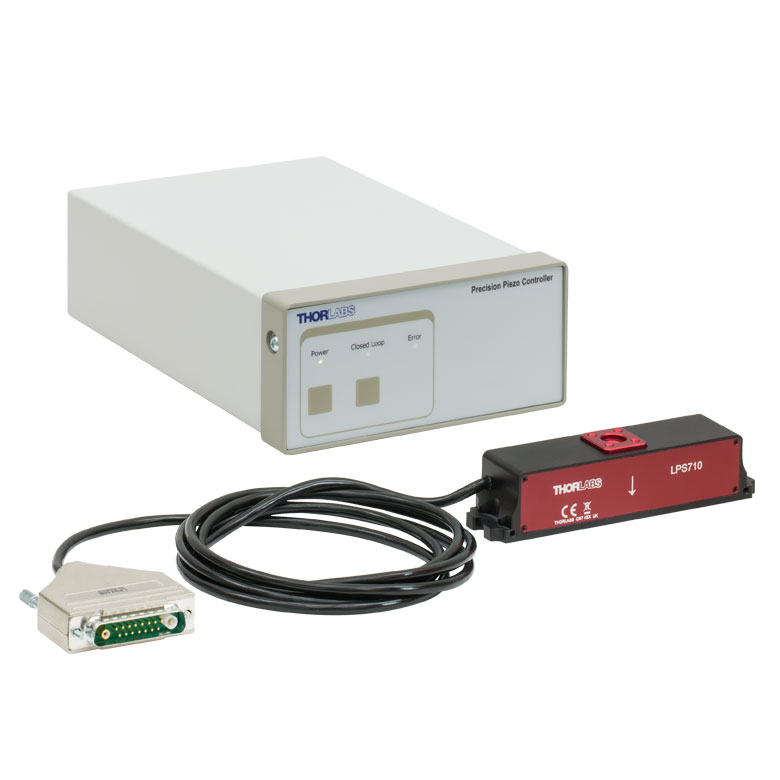 | |
| Travel | 20 µm + 5 mm Manual | 25 µm + 1.5 mm Manual | 28.0 mm | 60.0 mm | 1.1 mm | |
| Speed | - | 180 mm/s (Max) | 90 mm/s (Max) | - | ||
| Drive Type | Piezo with Manual Actuator | Resonant Piezoelectric Motor | Amplified Piezo | |||
| Possible Axis Configurations | X, XY, XYZ | X | Z | |||
| Mounting Surface Size | 75.0 mm x 75.0 mm | 30.0 mm x 30.0 mm | 15.0 mm x 15.0 mm | 21.0 mm x 21.0 mm | ||
| Additional Details | ||||||
ステッピングモーターステージ
こちらの移動ステージは脱着型あるいは内蔵型のステッピングモータを用いており、また300 mmまでの長い移動量が可能です。これらのステージの多くは多軸移動機能を有していたり(PLSXY)、あるいは多軸ステージを組み立てることが可能であったりします(PLSX、クイック接続型XR25シリーズ、LNRシリーズ、NRTシリーズ、LTSシリーズ)。ステージMLJ150/Mは高荷重にも対応する垂直移動ステージです。
| Stepper Motor Stages | |||||
|---|---|---|---|---|---|
| Product Family | MVSN1(/M) 13 mm Vertical Stage | PLS Series 1" Stages | Modular XR25 Series 25 mm Stage | LNR Series 25 mm Stage | LNR Series 50 mm Stage |
| Click Photo to Enlarge | 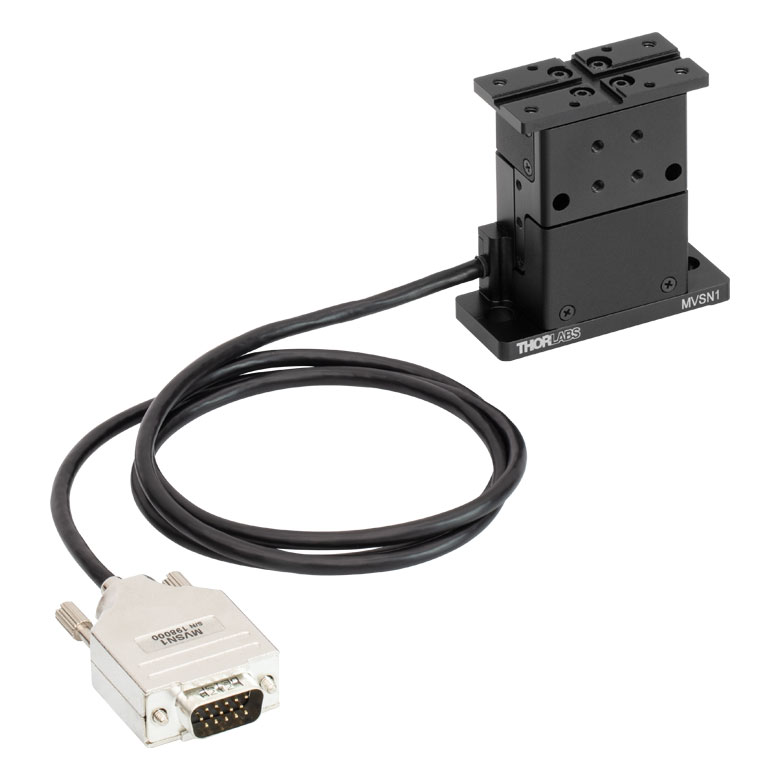 |  | 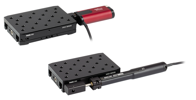 | 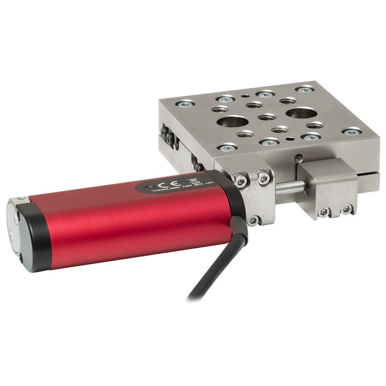 | 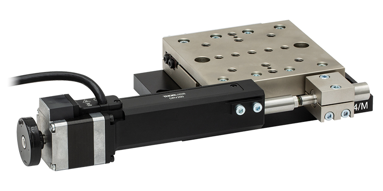 |
| Travel | 13 mm | 1" (25.4 mm) | 25 mm | 25 mm | 50 mm |
| Maximum Velocity | 5.0 mm/s | 7.0 mm/s | 2.0 mm/s | 2.0 mm/s | 50 mm/s |
| Possible Axis Configurations | Z | X, XY | X, XY, YZ, XZ, XYZ | X, XY, XYZ | X, XY, XYZ |
| Mounting Surface Size | 24.5 mm x 50.0 mm | 3" x 3" (76.2 mm x 76.2 mm) | 110.0 mm x 75.7 mm | 60 mm x 60 mm | 100 mm x 100 mm |
| Additional Details | |||||
| Stepper Motor Stages | ||||||
|---|---|---|---|---|---|---|
| Product Family | NRT Series 100 mm Stage | NRT Series 150 mm Stage | LTS Series 150 mm Stage | LTS Series 300 mm Stage | MLJ250 50 mm Vertical Stage | |
| Click Photo to Enlarge |  |  |  |  | 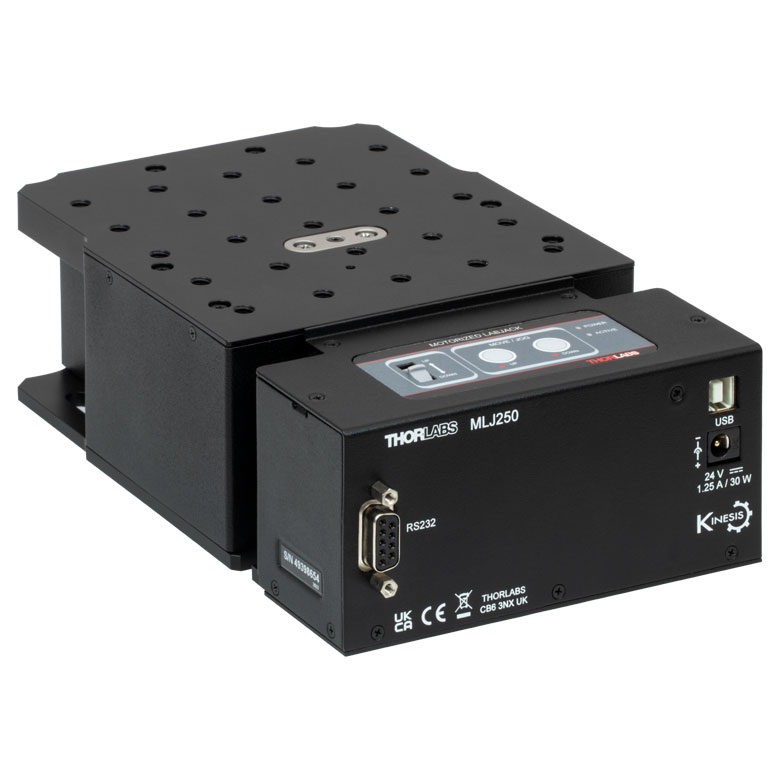 | |
| Travel | 100 mm | 150 mm | 150 mm | 300 mm | 50 mm | |
| Maximum Velocity | 30 mm/s | 50 mm/s | 3.0 mm/s | |||
| Possible Axis Configurations | X, XY, XYZ | X, XY, XYZ | Z | |||
| Mounting Surface Size | 84 mm x 84 mm | 100 mm x 90 mm | 148 mm x 131 mm | |||
| Additional Details | ||||||
DCサーボモーターステージ
脱着型あるいは内蔵型のDCサーボモータを用いた直線移動ステージをご用意しております。これらのステージは薄型で、多軸ステージの構築が可能です。
| DC Servo Motor Stages | ||||||
|---|---|---|---|---|---|---|
| Product Family | MT Series 12 mm Stages | PT Series 25 mm Stages | Compact Modular XNR25X 25 mm Stage | Modular XR25X 25 mm Stage | M30 Series 30 mm Stage | M30 Series 30 mm Monolithic XY Stage |
| Click Photo to Enlarge |  |  | 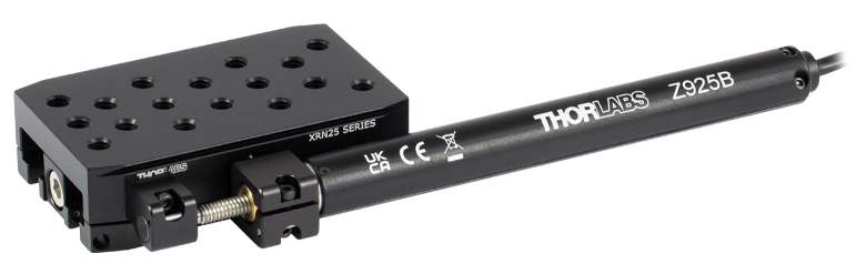 | 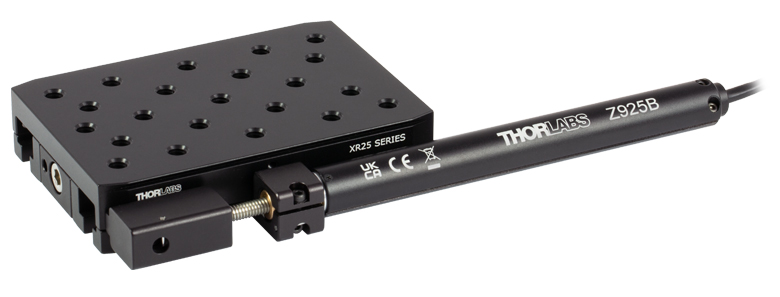 |  | 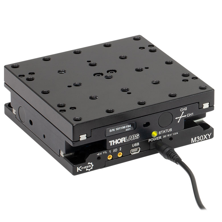 |
| Travel | 12 mm | 25 mm | 25 mm | 30 mm | ||
| Max Speed | 2.6 mm/s | 2.6 mm/sa | 2.4 mm/s | |||
| Possible Axis Configurations | X, XY, XYZ | X, XY, YZ, XZ, XYZ | X, Z | XY, XZ | ||
| Mounting Surface Size | 61.0 mm x 61.0 mm | 101.6 mm x 76.2 mm | 85.0 mm x 50.7 mm | 110.0 mm x 75.7 mm | 115.0 mm x 115.0 mm | |
| Additional Details | ||||||
| DC Servo Motor Stages | |||||
|---|---|---|---|---|---|
| Product Family | MTS Series 25 mm Stage | MTS Series 50 mm Stage | MTS Series 100 mm Stage | M150 Series 150 mm XY Stage | KVS30 30 mm Vertical Stage |
| Click Photo to Enlarge | 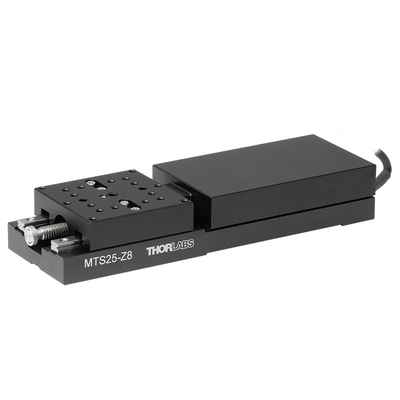 | 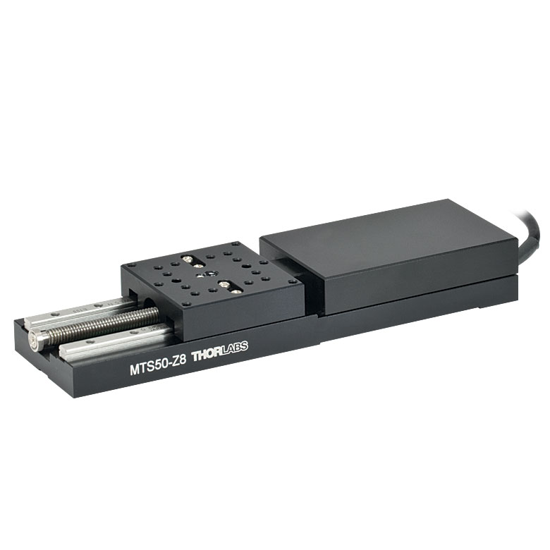 | 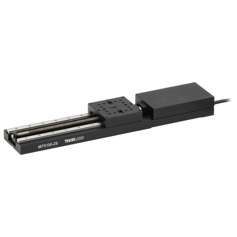 | 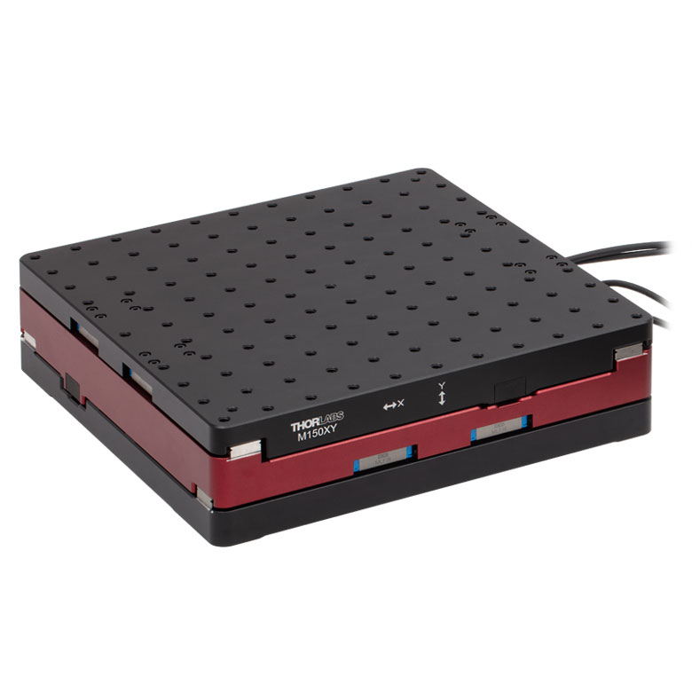 |  |
| Travel | 25 mm | 50 mm | 100 mm | 150 mm | 30 mm |
| Max Speed | 2.4 mm/s | X-Axis: 170 mm/s Y-Axis: 230 mm/s | 8.0 mm/s | ||
| Possible Axis Configurations | X, XY, XYZ | XY | Z | ||
| Mounting Surface Size | 43.0 mm x 43.0 mm | 272.4 mm x 272.4 mm | 116.2 mm x 116.2 mm | ||
| Additional Details | |||||
ダイレクトドライブステージ
こちらの薄型ステージにはブラシレスDCサーボモータが内蔵されており、バックラッシュの無い高速移動が可能です。電源が入ってないときは、ステージのプラットフォームにはほとんど慣性が無く、実質的にフリーラン状態になります。そのため電源が入ってないときにステージのプラットフォームが定位置に留まる必要のある用途には適していません。これらのステージを垂直方向に取付けることは推奨しません。
| Direct Drive Stages | |||||
|---|---|---|---|---|---|
| Product Family | DDS Series 50 mm Stage | DDS Series 100 mm Stage | DDS Series 220 mm Stage | DDS Series 300 mm Stage | DDS Series 600 mm Stage |
| Click Photo to Enlarge | 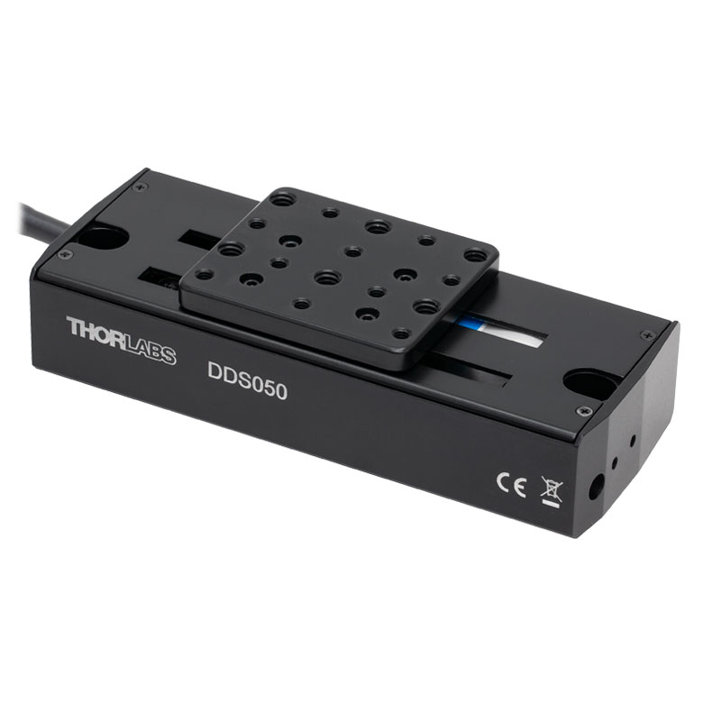 | 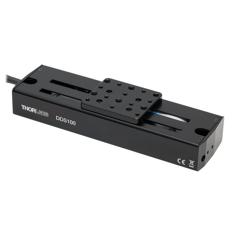 | 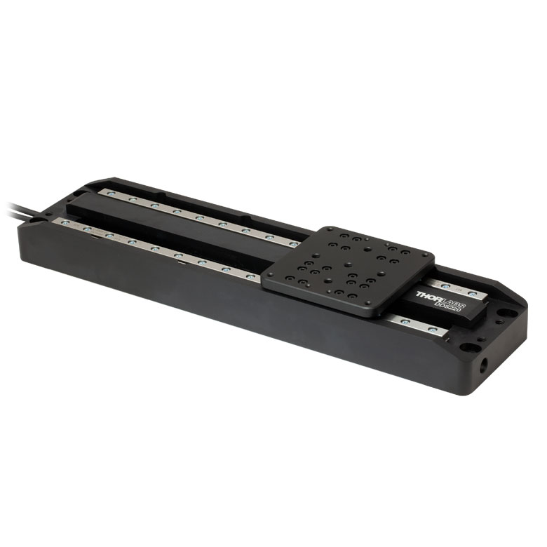 | 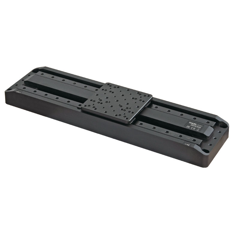 |  |
| Travel | 50 mm | 100 mm | 220 mm | 300 mm | 600 mm |
| Maximum Velocity | 500 mm/s | 300 mm/s | 400 mm/s | 400 mm/s | |
| Possible Axis Configurations | X, XY | X, XY | X | X | |
| Mounting Surface Size | 60 mm x 52 mm | 88 mm x 88 mm | 120 mm x 120 mm | ||
| Additional Details | |||||

 ズーム
ズーム
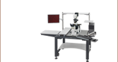
ステージNRT100/Mは、移動量が100 mmでステッピングモータが内蔵されています。 オプトメカニクスは、8つのM6タップ穴(25 mm間隔)を使用して、移動プラットフォームに直接取付け可能です。

 ズーム
ズームClick to Enlarge
直角ブラケットNRT150P1(/M)ならびに2つの移動ステージNRT100(/M)で構成されたXZアセンブリ
Click to Enlarge
ブレッドボードに直接取り付けたNRT150P1(/M)に移動ステージNRT100(/M)を垂直に取り付け
- XZならびにXYZステージアセンブリ構成用
- 光学テーブルに直接取り付けられることにより1軸の垂直移動を実現
直角ブラケットNRT150P1/Mはアルマイト加工アルミニウム製で、移動ステージNRT100/MまたはNRT150/Mを垂直に配置するための部品です。 このブラケットにより、XZならびにXYZの移動ステージを構築することができます(XZ構成は右端の写真参照)。 また、NRT150P1/Mは、1軸での垂直移動を必要とする用途向けに光学テーブルに直接取り付けることができます(右の写真参照)。
NRT150P1/Mのベース部分にはM6キャップスクリュ用のザグリ穴が6つ、側面にはM6タップ穴が2つあります。 側面の2つのタップ穴は、ステージを垂直に取り付けるために設定されています。

 ズーム
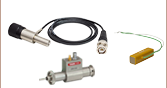
ズーム- 交換用モータ駆動ケーブル
- 長さ: 1 mまたは3 m
移動ステージNRTシリーズには、モータ駆動ケーブルPAA613が各1本付属しています。交換ケーブルは、付属ケーブルを紛失したり破損した場合にご用意しております。
ケーブルは当社のステッピングモータ付きアクチュエータにも接続可能です。 オス型のケーブル端はコントローラに、メス型はモータに接続します。