 Products Home
ステッピングモーター直線移動ステージ(リニアステージ)、移動量150 mm

- Stackable in XY, XZ, and XYZ Configurations
- Typical Calibrated On-Axis Accuracy of 2.0 µm
- Horizontal Load Capacity of 20 kg (44 lbs)
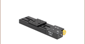
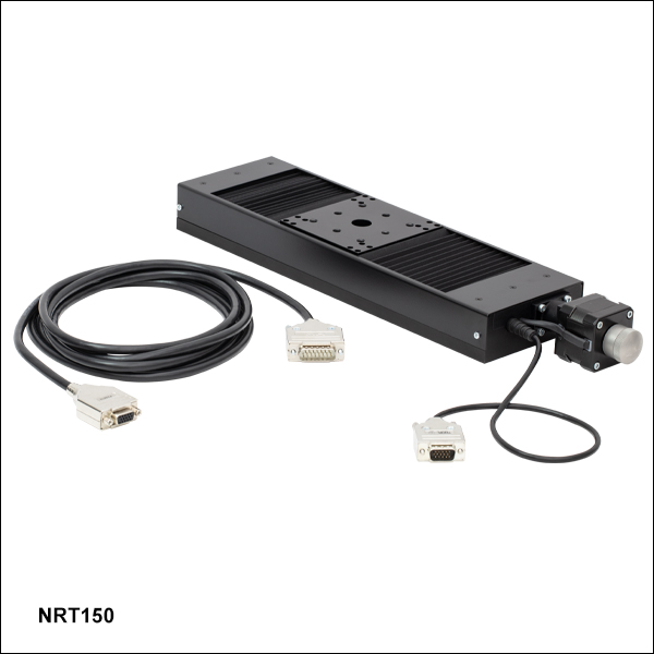
NRT150
150 mm Translation Stage
NRT150P1
Right-Angle Bracket
Application Idea
Three NRT150 Stages
in XYZ Configuration,
Using an NRT150P1
Right-Angle Adapter


Please Wait
| Key Specificationsa | |
|---|---|
| Travel Range | 150 mm (5.9") |
| Velocity (Max)b | 30 mm/s |
| Minimum Achievable Incremental Movement | 0.1 µm |
| On-Axis Accuracyc | 2.0 µm (Typical) 5.0 µm (Max) |
| Bidirectional Repeatabilityd | 1 µm |
| Backlashe | < 3 µm |
| Horizontal Load Capacity (Max) | 20 kg (44 lbs) |
| Vertical Load Capacity (Max) | 5 kg (11 lbs) |
| Actuator Type | Stepper Motor |
| Cable Length | 3.0 m (9.8 ft) |
| Recommended Controller | Benchtop Stepper Motor Controllers |
| Motorized Linear Translation Stages | |
|---|---|
| 100 mm | Stepper |
| DC Servo | |
| 150 mm | Stepper |
| Stepper with Integrated Controller | |
| 220 mm | DC Servo |
| 300 mm | Stepper with Integrated Controller |
| DC Servo | |
| 600 mm | DC Servo |
| Optical Delay Line Kits | |
| Other Translation Stages | |
特長
- 最大移動量:150 mm
- 耐荷重
- 水平設置時の荷重:20 kg
- 垂直設置時の荷重:5 kg
- 最高速度:30 mm/s
- 1 µmの双方向再現性
- XY、XZ、XYZに構成可能
- 標準的なオプトメカニクス取付け用M6タップ穴あり
当社の直線移動ステージ(リニアステージ)NRT150/Mは、測定や検査など高耐荷重かつ高分解能が必要な用途向けに最適化されています。 直線移動量は150 mmで、水平に設置した場合の耐荷重は20 kg、垂直に設置した場合は5 kgです。この自動ステージの典型的な軸確度は、付属の校正ファイルをKinesis®またはAPT™ソフトウェアに使用時2.0 µm(最大5.0 µm)となります。409,600マイクロステップ/回転の2相ステッピングモータによって直接駆動される送りネジは、理論的には100 nm未満の位置分解能でスムーズな移動を実現します。DCサーボモータの移動ステージとは異なり、 ステッピングモータ設計ではステージに電力供給がされていない時には、プラットフォームの位置は固定されます。
メインのプラットフォームは、リニアガイドレールに精密に配列された4つの再循環ボールベアリングで支えられています。 マイクロステップレベルの用途に対して設計されたステッピングモータは、より小さく滑らかな低速移動が可能で、DCサーボモータと比べて大幅に振動雑音が低減されています。 台形送りネジを採用したことにより、従来のアクメネジを使ったステージよりも耐久性が強化され、表面品質が向上したことで摩擦が少なくなり、バックドライブがほとんどないので通常のボールネジで必要となる制動機構が不要というような様々な利点があります。
校正ファイル
各リニア移動ステージNRT150/Mは製造時に校正されています。校正を行うと、コントローラがシステム内の機械的エラーを修正できるようになります。送りネジやリンク機構などの機械部品は、一定の許容差をもって製造されます。 このような機械的エラーは、指令位置から実際の位置までの誤差をもたらします。 しかしこのような誤差量には再現性があるため、KinesisまたはAPTソフトウェアと付属の校正ファイルを使用すれば補償することが可能です。付属の校正ファイルは、ユーザ入力の位置を必要な機械的モーションに変換します。校正ファイルは型番横の赤いアイコン )
)
校正ファイルの使用は任意ですが、このファイルをインストールしない場合、ステージの典型的な正確度は2.0 µmから19.29 µmに下がります。校正ファイルを使用しなくてもステージの再現性と分解能に影響はありません。
ステージの組合せ
XY構成をお考えの場合、リニア式位置決めステージNRT150/MやNRT100/M(移動量100 mm)を自由に組み合わせ、ステージのザグリ穴やスロットにM6キャップスクリュを使用して上下に取り付けることができます。 ザグリ穴は可動キャリッジのØ15.0 mm貫通穴からアクセスできます。 XZやXYZ構成には、NRT100/MまたはNRT150/Mを垂直方向に取り付けられる当社の垂直取付用ブラケットNRT150P1/Mがお使いいただけます。
コントローラ(別売り)
こちらの移動量150 mmの移動ステージには1チャンネル、2チャンネル、3チャンネルでご用意している当社のベンチトップ型ステッピングモータ用コントローラが必要です。PCからステージの制御を複雑な設定なしで行うことができます。また、LabVIEW、LabWindows™、ActiveXなどのプログラミングインターフェイスをサポートしています。
移動ステージNRTシリーズには、モータ駆動ケーブルPAA613が各1本付属しています。交換ケーブルは、付属ケーブルを紛失したり破損した場合にご用意しております。
| Item # | NRT150(/M) |
|---|---|
| Translation | |
| Travel Range | 150 mm (5.9") |
| Bidirectional Repeatabilitya | 1 µm |
| Backlashb | < 3 µm |
| Maximum Velocityc | 30 mm/s |
| Velocity Stability | ±0.1 mm/s |
| Maximum Accelerationc | 30 mm/s2 |
| Minimum Achievable Incremental Movementd | 0.10 µm |
| Minimum Repeatable Incremental Movemente | 2 µm |
| Accuracy | |
| Calibrated Absolute On-Axis Accuracy | 2.0 µm (Typical) 5.0 µm (Max) |
| Maximum Percentage Accuracyf | 0.09% |
| Home Location Accuracy | ±0.6 µm |
| Pitch | < 0.008° (140 µrad) |
| Yaw | < 0.05° (873 µrad) |
| Load Capacity | |
| Horizontal Load Capacity | < 12 kg (26 lbs) (Recommended) 20 kg (44 lbs) (Max) |
| Vertical Load Capacity | < 4 kg (9 lbs) (Recommended) 5 kg (11 lbs) (Max) |
| General | |
| Weight | 2.5 kg (5.5 lbs) |
| Dimensions | 412.9 mm x 100.0 mm x 43.5 mm (16.30" x 3.94" x 1.71") |
ステッピングモータ用駆動ケーブルPAA612ならびにPAA613
DA15オス型-DE15メス型
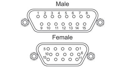
| DA15 Male Pin | DE15 Female Pin | Description |
|---|---|---|
| 11 and 12 | 1 | Limit Switch Ground |
| 10 | 2 | Forward Limit Switch |
| 9 | 3 | Reverse Limit Switch |
| 7 | 4 | Motor Phase B -ve |
| 14 | 5 | Motor Phase B +ve |
| 8 | 6 | Motor Phase A -ve |
| 15 | 7 | Motor Phase A +ve |
| 6 | 9 | Not Connected |
| 5 | 13 | Limit Switch +5 V |
モータ
Dタイプオス型
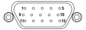
| Pin | Designation | Pin | Designation |
|---|---|---|---|
| 1 | Limit Switch Ground | 9 | Not Connected |
| 2 | Forward Limit Switch | 10 | Not Connected |
| 3 | Reverse Limit Switch | 11 | Not Connected |
| 4 | Motor Phase B -ve | 12 | Not Connected |
| 5 | Motor Phase B +ve | 13 | Limit Switch +5 V |
| 6 | Motor Phase A -ve | 14 | Not Connected |
| 7 | Motor Phase A +ve | 15 | Ground/Earth |
| 8 | Not Connected |
当社では幅広い種類のモーションコントローラを駆動できるよう、Kinesis® ソフトウェアパッケージと従来のAPT™(Advanced Positioning Technology)ソフトウェアパッケージの2種類のプラットフォームをご用意しております。どちらのパッケージも小型で低出力のシングルチャンネルドライバ(K-Cube™やT-Cube™など)から高出力でマルチチャンネルのモジュール式19インチラックナノポジショニングシステム(APTラックシステム)まで幅広い種類のモーションコントローラをカバーするKinesisシリーズのデバイスを制御できます。
Kinesisソフトウェアには、最新のC#、Visual Basic、LabVIEW™またはその他の.NETに対応する言語を使用してカスタムプログラムを作成するサードパーティの開発者向けに、.NETコントロールが付属しています。また、.NETフレームワークを使用しない用途向けに低級言語用のDLLライブラリも付いています。センターシーケンスマネージャが、当社の全てのモーションコントロールハードウェアの統合と同期をサポートします。

KinesisのGUIスクリーン
APTのGUIスクリーン
当社従来のAPTシステムソフトウェアプラットフォームは、C#、Visual Basic、LabVIEWまたはその他のActive-Xに対応する言語を使用してカスタムプログラムを作成するサードパーティの開発者向けに、ActiveXをベースとしたコントロールが付属しています。また、ハードウェア無しでカスタムプログラムの開発を行うためのシミュレーターモードも付いています。
これらの共通のソフトウェアプラットフォームにより、あらゆるKinesisとAPTコントローラをシングルアプリケーションに簡単に組み込むことができます。ソフトウェアツールは1セット習得するだけで共通した操作が可能です。シングルチャンネルシステムからマルチチャンネルシステムまで、あらゆるコントローラを組み合わせ、全てを1台のPCのソフトウェアインターフェイスから制御することが実現可能です。
このソフトウェアパッケージを使用するには2つの手段があります。GUI(グラフィカルユーザーインターフェイス)ユーティリティを使用したコントローラとの直接対話ならびに「out of the box」コントロール、またはご選択の開発言語でカスタム統合の位置決めやアライメントソリューションを簡単にプログラムできる一連のプログラミングインターフェイスです。
APTシステムソフトウェアをよりご理解いただけるために様々なチュートリアルビデオもご用意しております。ビデオではソフトウェアの概要とAPT Configユーティリティをご説明しています。また、ソフトウェアのシミュレーターモードを利用すると、コントローラを接続しないでソフトウェアを試すことができます。その方法を説明したビデオもあります。これらのビデオは「APTチュートリアル」タブ内のリンクからご覧いただけます。
ソフトウェア
Kinesis バージョン 1.14.47
このKinesisソフトウェアパッケージには、当社のKinesisならびにAPT™システムコントローラを制御するためのGUIが含まれています。
下記もご用意しております:
- 通信プロトコル
ソフトウェア
APT バージョン 3.21.6
このAPTソフトウェアパッケージには、当社のAPT™およびKinesisシステムコントローラを制御するためのGUIが含まれています。
下記もご用意しております:
- 通信プロトコル
Kinesis®ソフトウェアでは新しい.NETコントロールが使用でき、最新の最新のC#, Visual Basic, LabVIEW™、ほかの.NET対応言語を使用する開発者がカスタムにプログラムを作成することもできます。
C#
このプログラミング言語はマルチプログラミングパラダイムやマルチプログラミング言語が使用可能となるよう設計されているため、複雑な問題が簡単かつ効率的に解決できます。型付け、命令型、宣言型、関数型、ジェネリック、オブジェクト指向、そしてコンポーネント指向が含まれます。 この共通のソフトウェアプラットフォームにより、1セットのソフトウェアツールを習得するだけで、あらゆるKinesisコントローラを簡単に組み合わせることができます。このようにして1軸システムのコントローラから多軸システムのコントローラまで、様々なコントローラを組み合わせ、全てを1台のPCのソフトウェアインターフェイスから制御することが可能となりました。
Kinesisシステムソフトウェアを使用するには2つの手段があります。コントローラを直接つないで制御を行なう付属のGUI(グラフィカルユーザーインターフェイス)ユーティリティ、またはご希望の開発言語でカスタム仕様の位置決めやアライメントを簡単にプログラムできる一連のプログラミングインターフェイスです。
Kinesisモーションコントロールライブラリの構築の参考となる実行可能なプロジェクト機能拡張例については下のリンクをクリックしてください。なお、Quick Startのプロジェクト例の実行には別の統合開発環境(IDE)(Microsoft Visual Studioなど)が必要です。C#のプロジェクト例はKinesisソフトウェアパッケージに付属する.NETコントロールで実行可能です(詳細は「Kinesisソフトウェア」タブをご覧ください)。
 | Click Here for the Kinesis with C# Quick Start Guide Click Here for C# Example Projects Click Here for Quick Start Device Control Examples | |
LabVIEW
LabVIEWは、.Netコントロールを介してKinesisまたはAPTベースのコントローラとの通信に使用できます。LabVIEWでは、ツールとオブジェクトでフロントパネルとして知られるユーザーインターフェイスを構築した後、グラフィカル表記の関数を使ってコードを追加し、フロントパネルのオブジェクトを制御します。下記のLabVIEWチュートリアルでは.Netコントロールを使用してLabVIEW内KinesisまたはAPT駆動デバイス用の制御GUIを作成するための情報をご提供しています。 LabVIEWでコントローラを制御する基本的な方法や、LabVIEW GUIを用いてデバイスを操作する前に行うべき設定の手順についても解説しています。
 | Click Here to View the LabVIEW Guide Click Here to View the Kinesis with LabVIEW Overview Page | |
こちらのページでご覧いただくAPTビデオチュートリアルは、付属のATPユーティリティに関する説明と、いくつかのプログラミング環境におけるAPTシステムのプログラミングに関する説明の2つの部分から構成されています。
免責事項:これらの動画は、当初はAdobe Flashによって作成されました。2020年のAdobe Flashのサポート終了後、これらのチュートリアルは再録画されています。各動画の下にはFlash Playerの操作ボタンが見えますが、機能はしません。
APTコントローラには、APTUserユーティリティとAPTConfigユーティリティが付いています。APTUserを用いると、直感的操作が可能なグラフィック制御パネルを介して、APTで制御するハードウェアに素早く簡単に接続することができます。APTConfigは「オフライン」ユーティリティで、メカニカルステージのタイプを事前に選択し、それらを特定のモーションコントローラに対応付けるなど、システム全体のさまざまな設定を行うことができます。
APT Userユーティリティ
下の左側の動画では、APTUserユーティリティの操作概要について説明しています。シングルチャンネルコントローラのOptoDriverは、制御用のPCが無くても前面パネルのコントローラを介して操作できます。前面パネルのコントローラに保存されている操作に関する設定は、APTUserユーティリティを使用して変更することができます。そのプロセスは下の右側の動画でご覧いただけます。
APT Configユーティリティ
シミュレートされたハードウェア構成のセットアップや、メカニカルステージの特定のモータードライブチャンネルへの対応付けなど、APT Configユーティリティを使用してAPTシステム全体の様々な設定ができます。下の最初の動画ではAPT Configの概要をご覧いただけます。シミュレートされたハードウェア構成の作成方法やステージと対応付ける方法についての詳細は、その右側の2つの動画でご覧いただけます。
APTのプログラミング
APTソフトウェアシステムは、ActiveXコントロールのコレクションとして実装されています。ActiveXコントロールは言語に依存しないソフトウェアモジュールで、グラフィカルユーザーインターフェイスとプログラミングインターフェイスの両方を提供します。ハードウェアユニットのタイプごとにActiveXコントロールのタイプがあります。例えば、Motor ActiveXコントロールはすべてのタイプのAPTモーターコントローラ(DCまたはステッパ)の操作に対応します。ActiveXコントロールは多くのWindowsソフトウェア開発環境やソフトウェア言語で直接サポートされており、そのようなコントロールがカスタムアプリケーションに組み込まれると、そこに含まれるすべての機能が即座にアプリケーションで利用できるようになります。下の動画では、LabVIEW、Visual Basic、Visual C++によるAPT ActiveXコントロールの基本的な使用方法について説明しています。これ以外に、LabWindows CVI、C++ Builder、VB.NET、C#.NET、Office VBA、Matlab、HPVEEなどの多数の言語でもActiveXはサポートされています。これらの言語環境についてはチュートリアルのビデオでは特に取り上げていませんが、動画内の考え方の多くは他の言語環境でも適切に使用できます。
Visual Basic
Part 1ではVisual Basicで動作するAPT ActiveXコントロールを設定する方法について説明しており、Part 2では独自の位置決めシーケンスをプログラミングする方法について説明しています。
LabVIEW
LabVIEWはActiveXをフルサポートしています。下の一連のチュートリアルビデオでは、APTによる独自のモーションコントロールシーケンスを作製する際の基本的な構成要素を示しています。まずソフトウェア開発中にオンラインヘルプを呼び出す方法をご紹介します。Part 2ではAPT ActiveXコントロールの作成方法をご紹介します。ActiveXコントロールではメソッド(機能)とプロパティ(数値設定)の両方を設定できます。Part 3と4では、ActiveXコントロールで示されたメソッドとプロパティを作成してワイヤで接続する方法をご紹介します。最後に、Part 5では全体をまとめて、独自の移動シーケンスを実行するLabVIEWのプログラム例をご紹介します。
Part 1:オンラインヘルプへのアクセス方法
Part 2:ActiveXコントロールの作成方法
Part 3:ActiveXのメソッドの作成方法
Part 4:ActiveXのプロパティの作成方法
Part 5:ActiveXコントロールの開始方法
下のチュートリアルビデオでは、メソッドおよびプロパティのノードを作成する別の方法について説明しています。
ActiveXメソッドの作成方法(別の方法)
ActiveXプロパティの作成方法(別の方法)
Visual C++
Part 1ではVisualC++で動作するAPT ActiveXコントロールを設定する方法について説明しており、Part 2では独自の位置決めシーケンスをプログラミングする方法について説明しています。
MATLAB
当社のAPTポジショナにMATLABおよびActiveXコントロールを使用する場合は、こちらの資料をご覧ください。
プログラマー向けとして、LabVIEWでAPTソフトウェアをプログラミングする方法もこちらからご覧いただけます。
| Posted Comments: | |
Zhaoran Xu
(posted 2024-02-06 18:01:09.18) Hi Thorlabs,
We have a NRT150 stage with S/N 40863500. Recently we wanted to connect it to Kinesis but there is always an error that shows "Device not responding". I can see the stage is unloaded but connected. Everything is fine for our other two rotation stages. I just wonder how to fix this.
Thank you very much!
Best regards,
Zhaoran Xu cstroud
(posted 2024-02-14 12:00:18.0) Thanks for reaching out. We have contacted you directly to help troubleshoot your issue. pearsonmr
(posted 2018-01-24 13:01:53.227) Hi,
We already have an installed NRT150/M stage, and we are planning to wire it to a 3rd party controller. Can you tell me what the normal state of the active limit switches are when powered by the 5V? Normally open or normally closed?
Thanks,
Matthew bwood
(posted 2018-02-05 05:25:32.0) Response from Ben at Thorlabs: Thank you for your feedback. The limit switches are in a open collector and have a pull up on the stage. When the limit switch is activated the output pulls down to ground. When the limit switch is not activated the limit switch output is at 5volts. Looking at a BSC201 with this stage connected the limit switches are set to ‘switch makes’ so you can argue they are normally open and go closed on active wenzel.jakob
(posted 2017-12-11 23:43:24.29) How could a rigid stand (MP100) be mounted to this stage? I assume this will require some kind of intermediate adapter, as the counterbores of the MP100 have a 3x2" layout, while the NRT150 has a 2x2" moving surface) AManickavasagam
(posted 2017-12-15 10:11:13.0) Response from Arunthathi at Thorlabs: Thank you for your query.Unfortunately, the NRT150/M's plate is not large enough to mount MP100. However, you could use the LTS150/M which also is a stepper motor based stage and will have similar performance as the NRT150/M. user
(posted 2016-11-22 20:57:48.5) Bad quality and stops working often. bhallewell
(posted 2016-11-25 08:47:42.0) Response from Ben at Thorlabs: I'm sorry to hear of the bad experience you've had with this product. Please could you contact your local Tech Support office so that we can get in touch with you to troubleshoot the problems you're facing with the stage & provide you with a solution? asnl2
(posted 2014-06-16 11:39:02.003) Hi,
We have recently purchased a LTS150/M. However, I have some problems installing the calibration file. When I enter the APT Config the stage does not show up under the Stage Tab and rather than the 'stepper' dropdown selection box as described in the manual I have a 'motor' drop down box. When I try to assign a calibration file (motor set to none) I get the error message "Stage type selected is not compatible with selected driver. Please select stage type not prefixed by LTS or HTS LTS". I would greatly appreciate any help.
Best,
Anna bhallewell
(posted 2014-06-18 07:55:15.0) Response from Ben at Thorlabs: Thank you for your feedback. I will contact you directly to troubleshoot this process with you. jaboonfamily1
(posted 2013-10-15 16:20:40.303) Hi, I am interested in the NRT 150 but I'm not sure I read the specs correctly.
The displacement error once calibrated is "Calibrated Absolute On-axis Accuracy" and is around 2 microns right ? Isn't that weird that the minimum displacement is 0,1 micron then ?
As for the velocity, "Velocity Stability ±0.1 mm/sec" means 0,1 mm/s is the slowest reliable velocity I can set ?
Thank you. msoulby
(posted 2013-10-17 12:25:00.0) Response from Mike at Thorlabs: I will try to clarify what the specifications mean.
Minimum incremental motion: This is the actual minimum incremental motion that a stage can make, otherwise known as the minimum step size. This is calculated based on the minimum step size of a motor and the gearing in the stage. Typically the theoretical step size is smaller than actual achievable step size as there are several other factors such as friction, load, external forces, vibrations, type of controller and inertia. This has nothing to do with how accurate the stage is only what the smallest repeatable step size we can achieve is.
On axis accuracy: This is the absolute accuracy of the commanded position. It is defined as the maximum discrepancy between command position and absolute position over the full travel of the stage and should not be confused with repeatability. For example if a stage is specified with an on axis accuracy of 2µm then a command to travel to 10mm will result in an absolute position of within 2um of 10mm. This value will tell you the maximum possible inaccuracy at any point in your travel. However, sometimes a more useful specification can be maximum percentage accuracy as the discrepancy between command position and absolute position generally increases linearly with the amount of travel. This gives rise to an on axis accuracy which is generally much less than the accuracy at the beginning of the travel of the stage. The percentage accuracy can give you a good idea of what to typically expect along the stages travel.
The velocity stability was measured when the stage is moving at the maximum velocity and we will clarify this on the website, therefore this means that the maximum velocity is 30.0mm/s +/-0.1mm/s. the lowest velocity that can be entered for these stepper motors is around 40um/s which is limited by the controller code and software. You should also note that as these stages use a two phase stepper motor then low velocities could result in a jumpy, unstable velocity as the motor rotates and switches between each motor phase. For a more stable velocity you would need to use a 5 phase stepper motor, which thorlabs does not currently offer, or one of our direct drive linear stages such as the Thorlabs DDS220. bdada
(posted 2011-07-29 11:13:00.0) Response from Buki at Thorlabs:
I am sorry to hear about the issue you are having with the NRT150 motorized stage. We have contacted you to find out which controller you are using and to troubleshoot this matter further. vladimirlee
(posted 2011-07-29 00:01:25.0) Our NRT150 keeps showing that it reaches forward hardware limit no matter where it is. How to fix that? jjurado
(posted 2011-07-06 15:43:00.0) Response from Javier at Thorlabs to fg2251: Thank you very much for contacting us. We are currently developing an optical delay line kit which will be released later this month. This kit includes a 220 mm direct travel stage (DDS220, link below), a DC Servo controller, control software and extended programming through ActiveX controls, and all opto-mechanics including the periscope assembly. The minimum incremental motion is 0.1 um for your 100 fs delays. The pitch gives you the angular runout. For the DDS220 stage, 0.01 degree pitch will give you at least a 30um displacement. DDS220 and BBD101: http://www.thorlabs.com/NewGroupPage9.cfm?ObjectGroup_ID=5305&pn=DDS220#5305 We will contact you directly for further support. fg2251
(posted 2011-07-05 21:04:25.0) I am interested to the 150mm linear stage NRT150
My application is to build a delay line in a fs pump probe experiment.
My pulse duration is 100fs so I need a minimum motion on the order of 15micron
I need to delay the pump beam that after the delay line will be
focused on spot of 50-500micron, so the angular as well linear deviation
from straight line motion is critical for me.
I want some information:
Absolute on axis accuracy is 20micron. Is it referred to a motion of 150mm?
How much the cost will be with the calibration?
What about the linear and angular runout? Is it the pitch and Yaw?
Do you have other suggestion for my application?
Can you provide the stepper controller with labview software for integration on my setup (lock in amplifier, DAC..)?
Let me know
Felice jjessop
(posted 2009-11-30 11:00:12.0) A response from Jonathan to cjc16: Im afraid we wont be able to offer this. You could try doing this work youself, but the hall effect switchs are set to give the correct position. cjc16
(posted 2009-11-16 13:17:41.0) I have purchased an NRT150 and I am in the process of wiring it to be compatible with our drive system. I found that you are using proximity switches that require 5v power but we typically use NC mechanical switches with our hardware. Do you have an option to retrofit mechanical switches in place of the proximity switches? klee
(posted 2009-09-14 17:18:57.0) A response from Ken at Thorlabs to jbotha: The bearing can take 18.7Nm moment in x (longitudinal, direction of travel) and 18.7Nm in y. There are two, so the shift of where the moment is actually pulling is quite complicated but it should be fine as you wont get a 90/10 split in how the load is distributed. Becuase of the unusal angle of the force on the lead screw you might have to reduce velocities but it should be fine. jbotha
(posted 2009-09-03 04:26:00.0) Hi,
Very much interested in you NRT150-product. I do have the following question which will determine whether or not this product is suitable for our application which I could not find among your specifications listed:
What is the maximum permissible moment allowed on the sliding table of the NRT150? The application we want to bolt on to the sliding table has an offset center of gravity which will exert a maximum of 20 Nm around the longitudinal axis and 10 Nm around the transverse axis.
Thank you in advance for your assistance!
Kind regards,
Jan Botha Tyler
(posted 2008-06-13 08:22:24.0) A response from Tyler at Thorlabs to Ian: In an effort to keep our drawings uncluttered enough to be readable we only display a limited number of dimensions. If the dimension you are looking for is not displayed you can contact an applications engineer at Thorlabs or load the ParaSolid, eDrawing, or Step file and measure the dimension using the softwares measurement tool. eDrawings is a free web browser download that can be used to view the ParaSolid and eDrawing files. I will have an applications engineer contact you to avoid confusion and make sure that you are getting the dimension that you have requested. Thank you for your interest in our translation stage. ian.mills2
(posted 2008-06-11 10:18:54.0) Is the carriage shown 75mm from the central position on the drawing?
There are no dimensions from the carriage to the end of the stage.
It would be helpful to know where the limits are. cjohns
(posted 2007-09-17 12:28:39.0) I see that there is a picture of the NST150 above, yet the part comes up in the search as superseeded. |
電動リニアステージ
電動の直線移動ステージとしては、ピエゾ駆動の20 µm移動ステージからダイレクトドライブ方式の600 mm移動ステージまで、様々な最大移動量の製品をご用意しております。ステージの多くは、それらを用いてXY軸やXYZ軸などの多軸ステージを構築することができます。ファイバ結合用としては、多軸ステージのページをご覧ください。標準の電動ステージを用いるよりも精密な調整が可能です。直線移動ステージのほかに、電動の回転ステージおよびゴニオステージもご用意しております。また手動移動ステージもございます。
ピエゾステージ
これらのステージでは、様々な駆動機構にピエゾ素子が組み込まれています。ステージORIC®シリーズでは、「スティック-スリップ」と呼ばれる摩擦特性を利用したピエゾ慣性アクチュエータが用いられており、それにより長い移動距離が得られています。移動ステージNanoflex™シリーズは、手動アクチュエータに加えて標準的なピエゾアクチュエータが用いられています。ステージElliptec®シリーズでは共振ピエゾモータが用いられており、共振に伴うモータ先端の楕円形の動きで可動プラットフォームを押したり引いたりします。Z軸ステージLPS710E/Mにはピエゾ移動に対する機械的な増幅機構が組み込まれており、またそれに適したコントローラが付属しています。
| Piezoelectric Stages | ||||
|---|---|---|---|---|
| Product Family | ORIC® PDXZ1 Closed-Loop 4.5 mm Vertical Stage | ORIC® PD2 Open-Loop 5 mm Stage | ORIC® PDX2 Closed-Loop 5 mm Stage | |
| Click Photo to Enlarge | 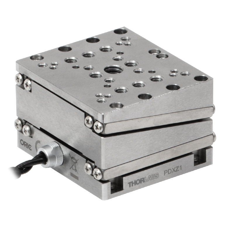 |  |  | |
| Travel | 4.5 mm | 5 mm | ||
| Speed | 1 mm/s (Typ.)a | 10 mm/s (Typ. Max)b | 8 mm/s (Typ.)c | |
| Drive Type | Piezoelectric Inertia Drive | |||
| Possible Axis Configurations | Z | X, XY, XYZ | ||
| Mounting Surface Size | 45.0 mm x 42.0 mm | 13 mm x 13 mm | ||
| Additional Details | ||||
| Piezoelectric Stages | |||||
|---|---|---|---|---|---|
| Product Family | ORIC® PD1 Open-Loop 20 mm Stage | ORIC® PD1D Open-Loop 20 mm Monolithic XY Stage | ORIC® PDX1 Closed-Loop 20 mm Stage | ORIC® PD3 Open-Loop 50 mm Stage | |
| Click Photo to Enlarge | 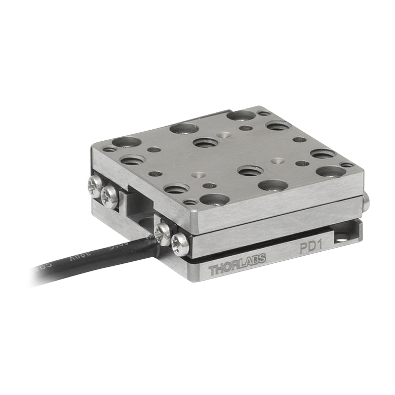 | 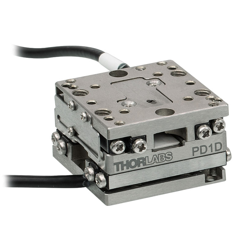 | 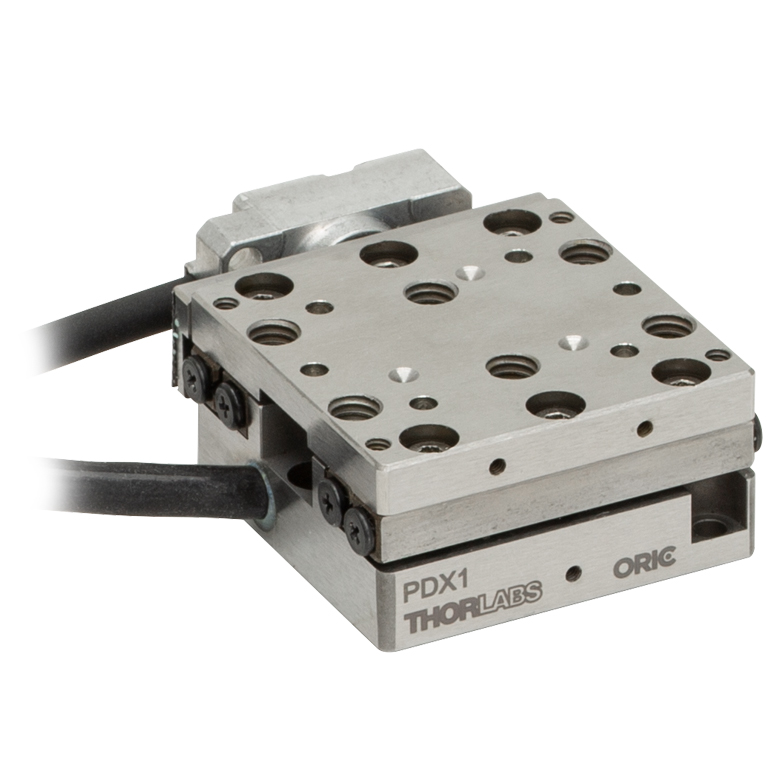 |  | |
| Travel | 20 mm | 50 mm | |||
| Speed | 3 mm/s (Typ. Max)a | 20 mm/s (Typ. Max)b | 10 mm/sc | ||
| Drive Type | Piezoelectric Inertia Drive | ||||
| Possible Axis Configurations | X, XY, XYZ | XY, XYZ | X, XY, XYZ | X, XY, XYZ | |
| Mounting Surface Size | 30 mm x 30 mm | 80 mm x 30 mm | |||
| Additional Details | |||||
| Piezoelectric Stages | ||||||
|---|---|---|---|---|---|---|
| Product Family | Nanoflex™ 20 µm Stage with 5 mm Actuator | Nanoflex™ 25 µm Stage with 1.5 mm Actuator | Elliptec® 28 mm Stage | Elliptec® 60 mm Stage | LPS710E 1.1 mm Vertical Stage | |
| Click Photo to Enlarge | 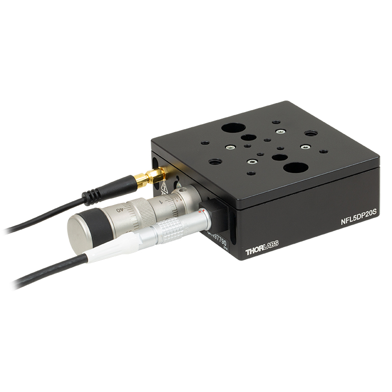 | 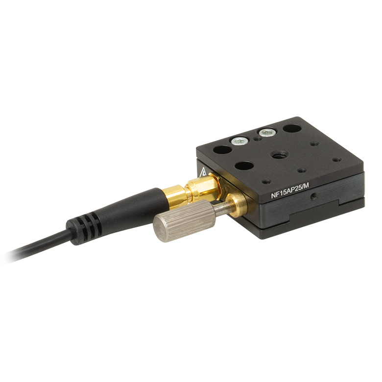 | 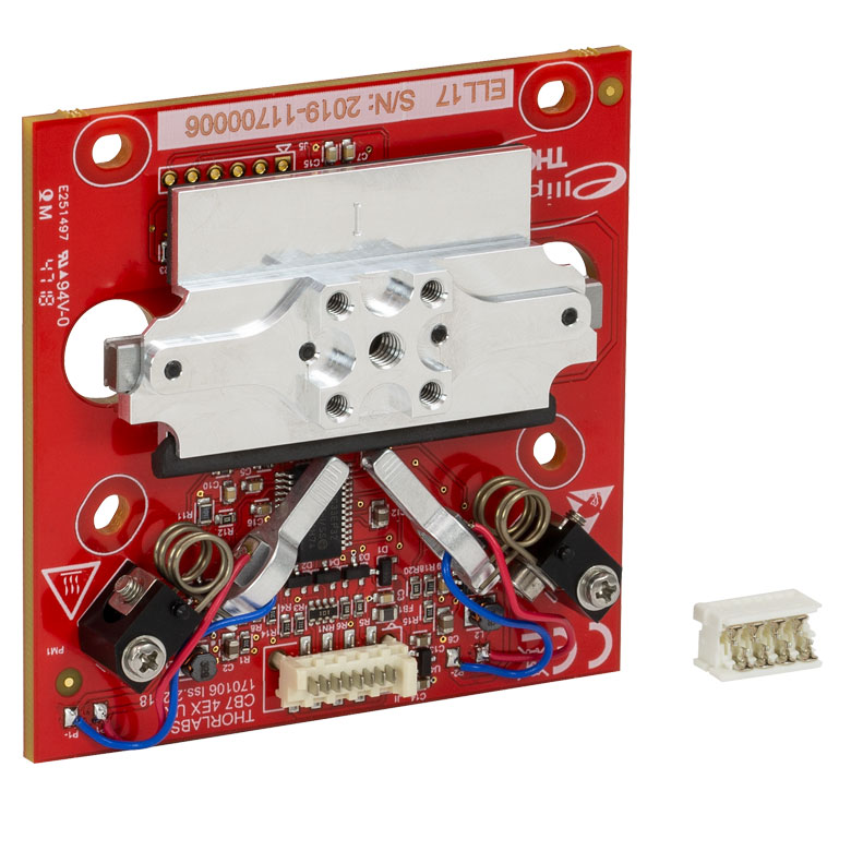 | 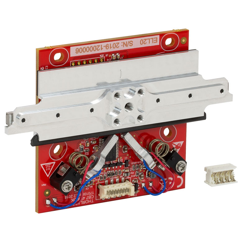 | 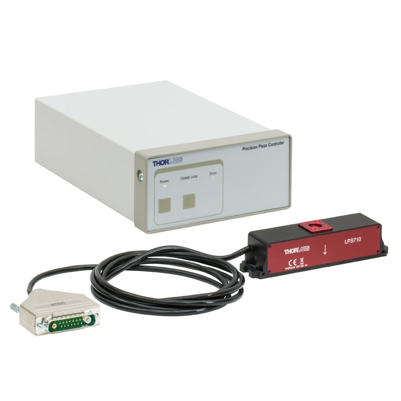 | |
| Travel | 20 µm + 5 mm Manual | 25 µm + 1.5 mm Manual | 28 mm | 60.0 mm | 1.1 mm | |
| Maximum Velocity | - | 180 mm/s | 90 mm/s | - | ||
| Drive Type | Piezo with Manual Actuator | Resonant Piezoelectric Motor | Amplified Piezo | |||
| Possible Axis Configurations | X, XY, XYZ | X | Z | |||
| Mounting Surface Size | 75 mm x 75 mm | 30 mm x 30 mm | 15 mm x 15 mm | 21 mm x 21 mm | ||
| Additional Details | ||||||
ステッピングモーターステージ
こちらの移動ステージは脱着型あるいは内蔵型のステッピングモータを用いており、また300 mmまでの長い移動量が可能です。ステージの多くは多軸構成(PLSXY)や、多軸ステージ(PLSX、LNRシリーズ、NRTシリーズ、LTSシリーズ)への組み込みが可能です。ステージMLJ150/Mは高荷重にも対応する垂直移動ステージです。
| Stepper Motor Stages | |||||
|---|---|---|---|---|---|
| Product Family | PLSX with and without PLST(/M) Top Plate 1" Stage | PLSXY with and without PLST(/M) Top Plate 1" Stage | LNR Series 25 mm Stage | LNR Series 50 mm Stage | |
| Click Photo to Enlarge | 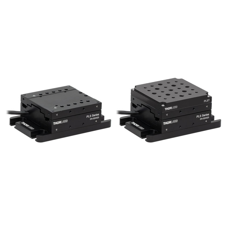 | 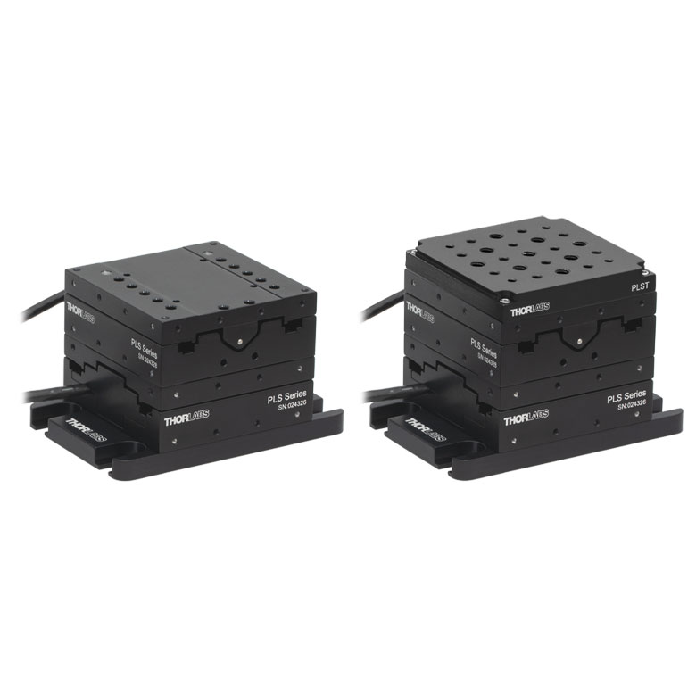 | 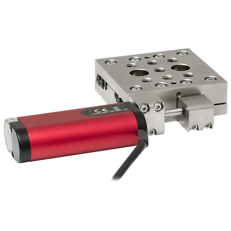 | 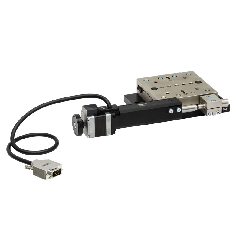 | |
| Travel | 1" | 25 mm | 50 mm | ||
| Maximum Velocity | 7.0 mm/s | 2.0 mm/s | 50 mm/s | ||
| Possible Axis Configurations | X, XY | X, XY, XYZ | X, XY, XYZ | ||
| Mounting Surface Size | 3" x 3" | 60 mm x 60 mm | 100 mm x 100 mm | ||
| Additional Details | |||||
| Stepper Motor Stages | ||||||
|---|---|---|---|---|---|---|
| Product Family | NRT Series 100 mm Stage | NRT Series 150 mm Stage | LTS Series 150 mm Stage | LTS Series 300 mm Stage | MLJ250 50 mm Vertical Stage | |
| Click Photo to Enlarge |  | 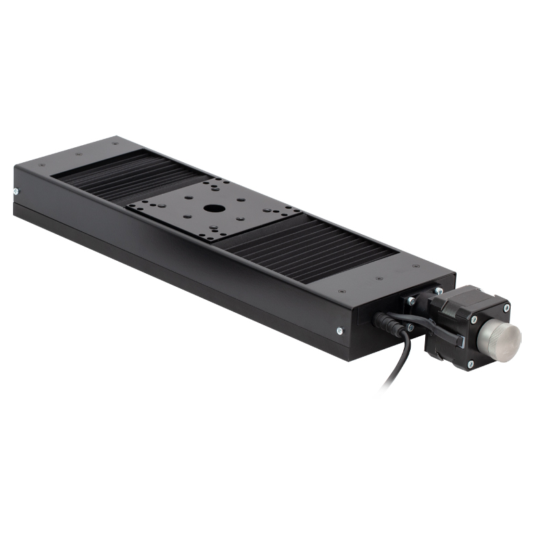 | 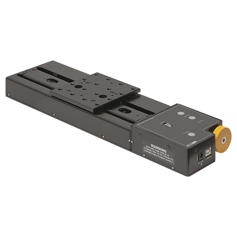 |  | 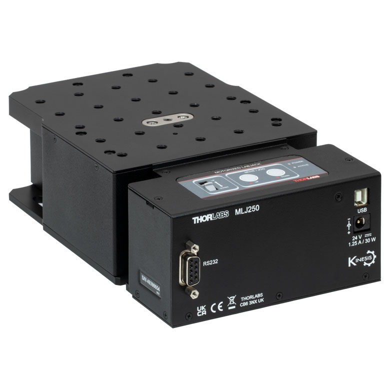 | |
| Travel | 100 mm | 150 mm | 150 mm | 300 mm | 50 mm | |
| Maximum Velocity | 30 mm/s | 50 mm/s | 3.0 mm/s | |||
| Possible Axis Configurations | X, XY, XYZ | X, XY, XYZ | Z | |||
| Mounting Surface Size | 84 mm x 84 mm | 100 mm x 90 mm | 148 mm x 131 mm | |||
| Additional Details | ||||||
DCサーボモーターステージ
脱着型あるいは内蔵型のDCサーボモータを用いた直線移動ステージをご用意しております。これらのステージは薄型で、多軸ステージの構築が可能です。
| DC Servo Motor Stages | ||||
|---|---|---|---|---|
| Product Family | MT Series 12 mm Stages | PT Series 25 mm Stages | MTS Series 25 mm Stage | MTS Series 50 mm Stage |
| Click Photo to Enlarge |  |  | 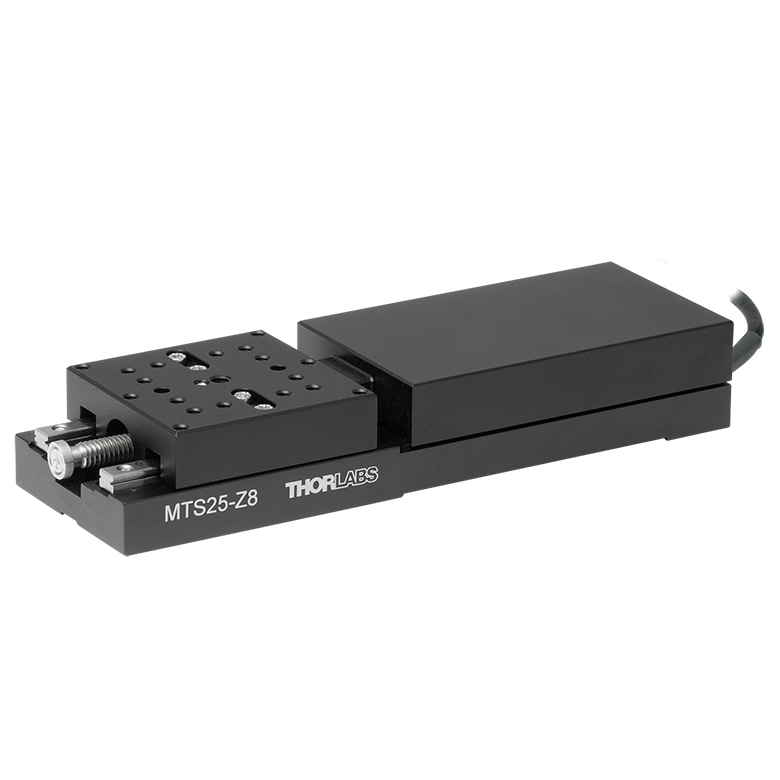 | 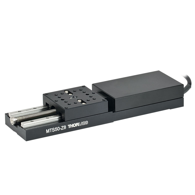 |
| Travel | 12 mm | 25 mm | 25 mm | 50 mm |
| Maximum Velocity | 2.6 mm/s | 2.4 mm/s | ||
| Possible Axis Configurations | X, XY, XYZ | X, XY, XYZ | ||
| Mounting Surface Size | 61 mm x 61 mm | 101.6 mm x 76.2 mm | 43 mm x 43 mm | |
| Additional Details | ||||
| DC Servo Motor Stages | ||||
|---|---|---|---|---|
| Product Family | M30 Series 30 mm Stage | M30 Series 30 mm Monolithic XY Stage | M150 Series 150 mm XY Stage | KVS30 30 mm Vertical Stage |
| Click Photo to Enlarge |  | 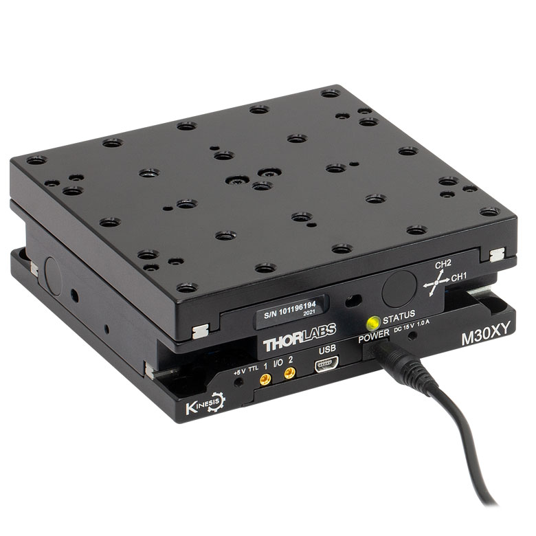 | 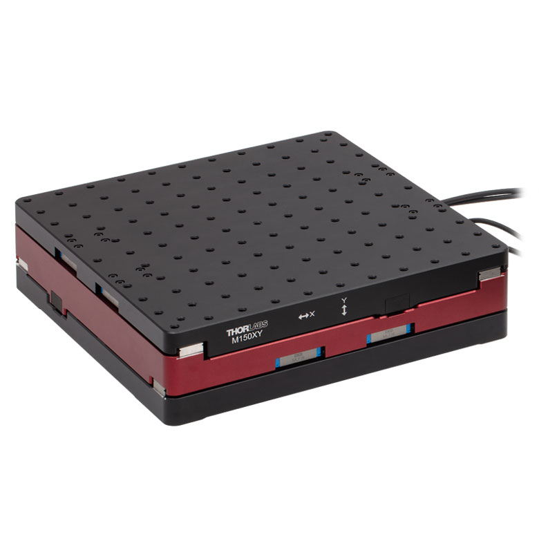 |  |
| Travel | 30 mm | 150 mm | 30 mm | |
| Maximum Velocity | 2.4 mm/s | X-Axis: 170 mm/s Y-Axis: 230 mm/s | 8.0 mm/s | |
| Possible Axis Configurations | X, Z | XY, XZ | XY | Z |
| Mounting Surface Size | 115 mm x 115 mm | 272.4 mm x 272.4 mm | 116.2 mm x 116.2 mm | |
| Additional Details | ||||
ダイレクトドライブステージ
こちらの薄型ステージにはブラシレスDCサーボモータが内蔵されており、バックラッシュの無い高速移動が可能です。電源が入ってないときは、ステージのプラットフォームにはほとんど慣性が無く、実質的にフリーラン状態になります。そのため電源が入ってないときにステージのプラットフォームが定位置に留まる必要のある用途には適していません。これらのステージを垂直方向に取付けることは推奨しません。
| Direct Drive Stages | |||||
|---|---|---|---|---|---|
| Product Family | DDS Series 50 mm Stage | DDS Series 100 mm Stage | DDS Series 220 mm Stage | DDS Series 300 mm Stage | DDS Series 600 mm Stage |
| Click Photo to Enlarge | 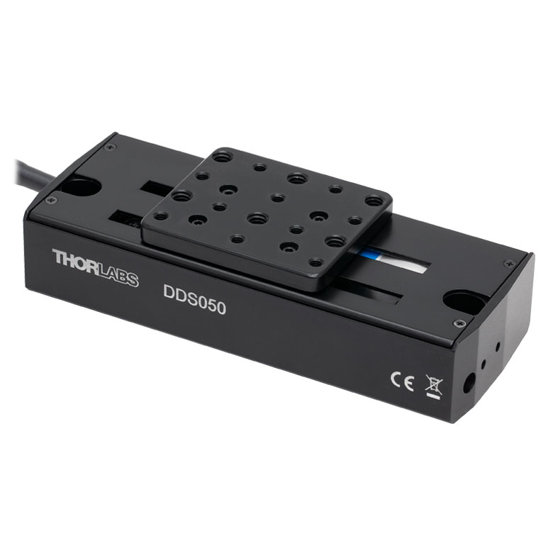 | 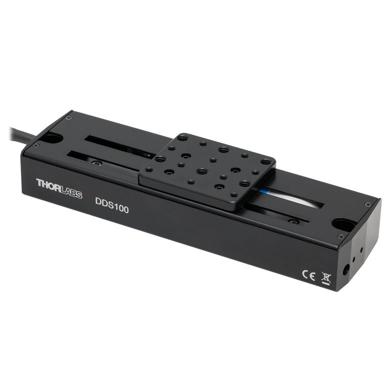 | 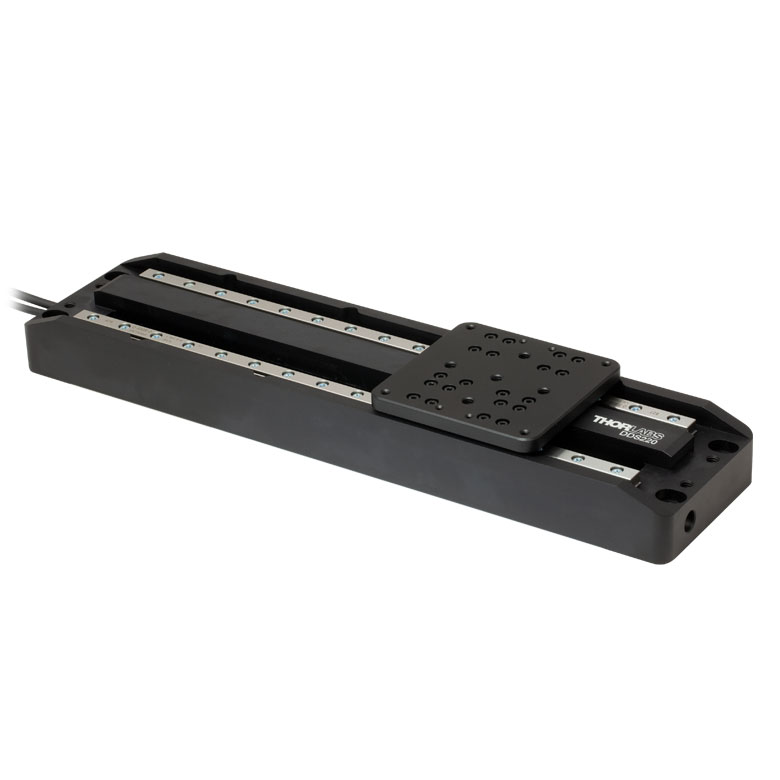 | 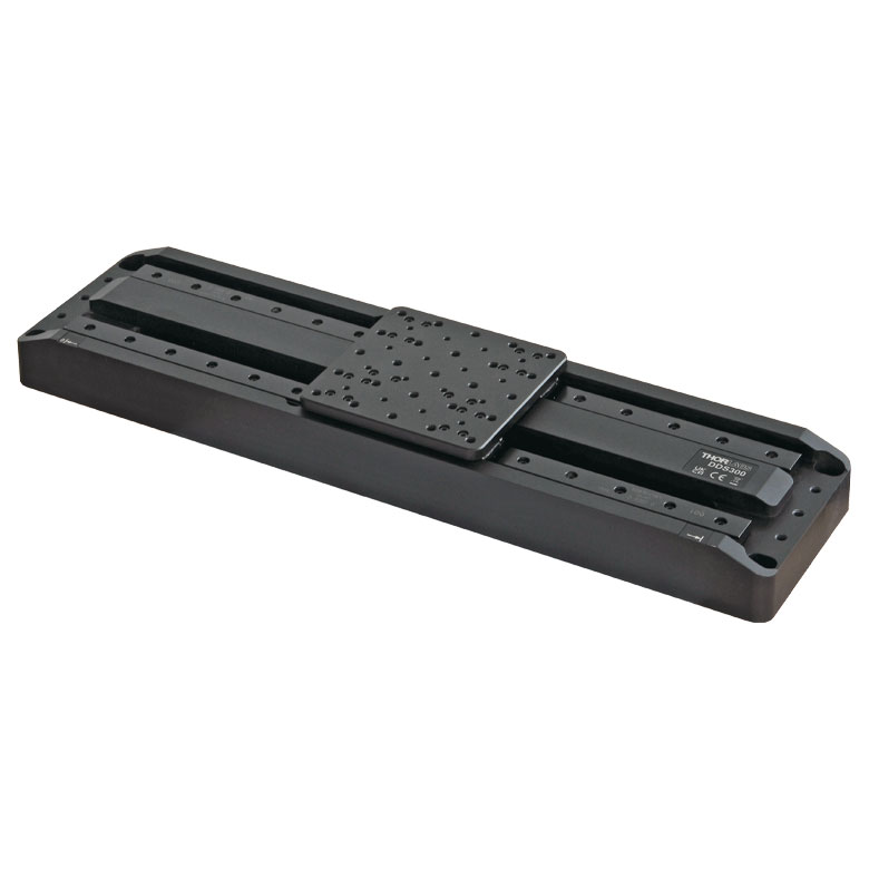 |  |
| Travel | 50 mm | 100 mm | 220 mm | 300 mm | 600 mm |
| Maximum Velocity | 500 mm/s | 300 mm/s | 400 mm/s | 400 mm/s | |
| Possible Axis Configurations | X, XY | X, XY | X | X | |
| Mounting Surface Size | 60 mm x 52 mm | 88 mm x 88 mm | 120 mm x 120 mm | ||
| Additional Details | |||||

 ズーム
ズーム
当社の移動ステージNRT150/Mの移動量は150 mmで、ステッピングモータが内蔵されています。 可動式プラットフォームに25.0 mm間隔で開いている8個のM6タップ穴を利用して、オプトメカニクスを直接取り付けることができます。

 ズーム
ズーム
Click to Enlarge
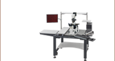
直角ブラケットNRT150P1(/M)ならびに3つの移動ステージNRT150(/M)で構成されたXYZアセンブリ
Click to Enlarge
ブレッドボードに直接取り付けたNRT150P1(/M)に移動ステージNRT150(/M)を取り付け
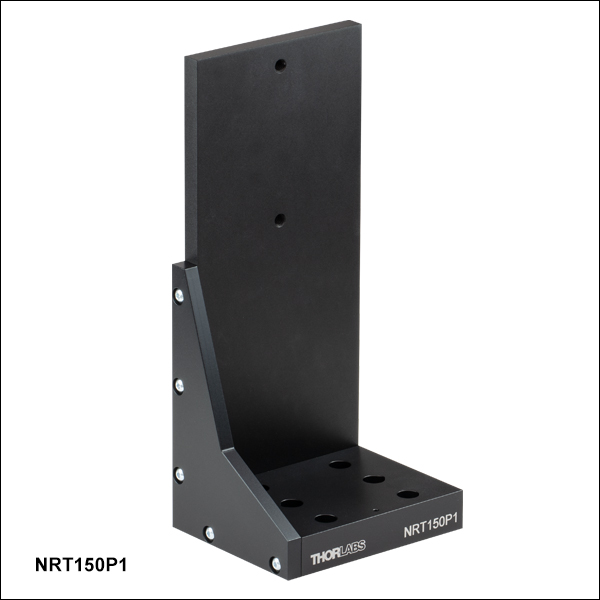
- XZならびにXYZステージアセンブリ構成用
- 光学テーブルに直接取り付けられることにより1軸の垂直移動を実現
直角ブラケットNRT150P1/Mはアルマイト加工アルミニウム製で、移動ステージNRT150/MまたはNRT100/Mを垂直に配置するための部品です。 このブラケットにより、XZならびにXYZの移動ステージを構築することができます(XYZ構成は右端の写真参照)。 また、NRT150P1(/M)は、1軸での垂直移動を必要とする用途向けに光学テーブルに直接取り付けることができます(右の写真参照)。
NRT150P1/Mのベース部分にはM6キャップスクリュ用のザグリ穴が6つ、側面にはM6タップ穴が2つあります。 側面の2つのタップ穴は、ステージを垂直に取り付けるために設定されています。

 ズーム
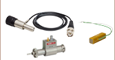
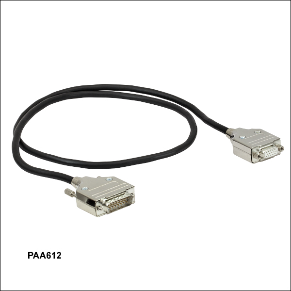
ズーム- 交換用モータ駆動ケーブル
- 長さ: 1 mまたは3 m
移動ステージNRTシリーズには、モータ駆動ケーブルPAA613が各1本付属しています。交換ケーブルは、付属ケーブルを紛失したり破損した場合にご用意しております。
ケーブルは当社のステッピングモータ付きアクチュエータにも接続可能です。 オス型のケーブル端はコントローラに、メス型はモータに接続します。