 Products Home / 自動(電動)ステージ / 電動直線移動ステージ(リニアステージ) / 電動直線移動ステージ(リニアステージ):移動量100 mm以上 / ブラシレスDCサーボモーター直線移動ステージ(リニアステージ)、ダイレクトドライブ型、移動量100 mm
ブラシレスDCサーボモーター直線移動ステージ(リニアステージ)、ダイレクトドライブ型、移動量100 mm
- 100 mm Travel at Speeds Up to 500 mm/s
- Brushless DC Servo Motors
- Stackable in XY Configuration
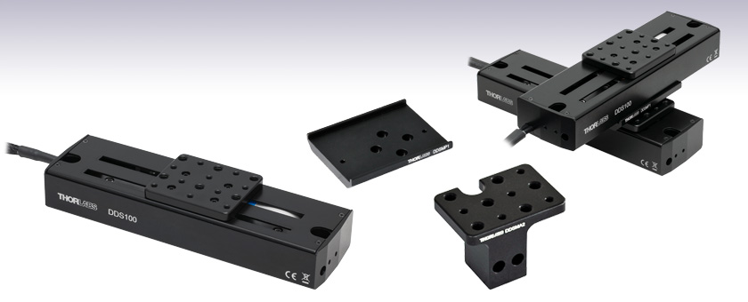
DDS100
100 mm (3.9") Servo Motor
Translation Stage
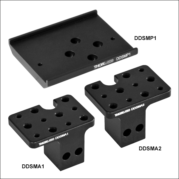
DDSMA2
End Mounting Adapter
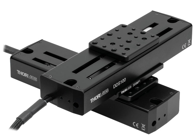
Application Idea
Two DDS100 Stages in
XY Configuration,
Using an DDSMP1 Adapter Plate
DDSMP1
XY Adapter Plate


Please Wait
| Item # | DDS100(/M) |
|---|---|
| Travel Range | 100 mm (3.9") |
| Speed (Max)a | 500 mm/s |
| Acceleration (Max) | 5000 mm/s2 |
| Bidirectional Repeatabilityb | ±1.5 µm |
| Straightness/Flatness | ±5.0 µm |
| Horizontal Load Capacity (Max) | 0.9 kg (1.98 lbs) |
| Min Incremental Movementc | 5.0 µm |
| Absolute On-Axis Accuracy | ±6.5 µm |
| Actuator Type | Brushless DC Servo Motor |
| Dimensions (L x W x H) | 195.0 mm x 57.0 mm x 35.0 mm (7.68" x 2.24" x 1.38") |
特長
- 移動量:100 mm
- ブラシレスDCリニアサーボモータ内蔵
- 光学式リニアエンコーダ
- 高品質で精密なリニアベアリング
- 水平耐荷重0.9 kg
- XY構成にスタック可能
DDS100/Mは、移動量100 mm、軸上精度±6.5 µm、最高移動速度500 mm/sの薄型ダイレクトドライブ直線移動ステージ(リニアステージ)です。この自動ステージは、自動アライメント、表面検査、マッピング、プロービングをはじめとする、高速で高精度の位置決めを必要とする用途に適しています。
ブラシレスリニアモータを内蔵した薄型設計を採用したことで、機械的な衝突や移動プラットフォームにアクセスする際の妨げの原因となる外部筐体を取り除きました。ブラシレスDCサーボモータは送りネジを必要としないためバックラッシュが生じません。また、内部にフレキシブルな管路を設けたため、機構部分が動いてもケーブル類が引っ掛かりません。精密溝付きのリニアベアリングによって、優れた剛性と直線性、および高い軸上精度を実現しています。バックラッシュのない操作性と高分解能の閉ループ光学フィードバックにより、±1.5 μmという高い双方向再現性が得られています。
Click to Enlarge
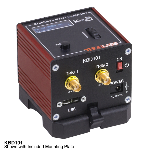
これらのステージを駆動するには、K-CubeブラシレスDCサーボモーターコントローラKBD101(別売り、下記参照)が必要です。
| Motorized Linear Translation Stages | |
|---|---|
| 100 mm | Stepper |
| DC Servo | |
| 150 mm | Stepper |
| Stepper with Integrated Controller | |
| 220 mm | DC Servo |
| 300 mm | Stepper with Integrated Controller |
| DC Servo with Benchtop Controller | |
| 600 mm | DC Servo with Benchtop Controller |
| Optical Delay Line Kits | |
| Other Translation Stages | |
コントローラ
ダイレクトドライブの直線移動ステージDDS100/Mを操作するには、K-Cube®ブラシレスDCモーターコントローラKBD101が必要です。コントローラではS字加減速を自由に設定できるため、振動や衝撃の無い高速で滑らかな位置決めが可能です。ブラシレスDCモーターコントローラの製品概要については下記をご覧ください。またはこちらをクリックして詳しい製品説明をご参照ください。
取付けアダプタ
2軸構成が必要な場合には、上の写真のようにXYアダプタープレートDDSMP1/Mを用いて2つのステージをボルトで固定し、XYステージを構成することができます。なおこのステージは垂直方向(Z軸)の移動には適していません。詳しくは当社までお問い合わせください。
ディレイラインを構築するときのように、リニア移動ステージに近接してオプトメカニクス部品を取り付けたいときに利用できる、アダプターブラケットもご用意しております。詳細については下記をご参照ください。
注:磁性部品はステージのプラットフォーム上には取り付けないでください。磁界により正確なホーミングができなくなり、磁性部品を取り外した後もステージのエンコーダの精度に影響を及ぼす可能性があります。電源が入ってないときのプラットフォームは、ほとんど慣性の無い実質的にフリーランの状態になります。そのため、電源が入ってないときには定めた位置に留まっていることが求められる用途には適しません。
| Item # | DDS100(/M) |
|---|---|
| Travel Range | 100 mm (3.9") |
| Speed (Max)a | 500 mm/s |
| Speed (Min)b | 70 nm/s |
| Acceleration (Max) | 5000 mm/s2 |
| Acceleration (Max) at 0.9 kg Load | 500 mm/s2 |
| Resolution | 500 nm |
| Bidirectional Repeatabilityc | ±1.5 µm |
| Backlash | N/A (No Leadscrew) |
| Min Incremental Movementd | 5.0 µm |
| Horizontal Load Capacity (Max) | 0.9 kg (1.98 lbs) |
| Absolute On-Axis Accuracy | ±6.5 µm |
| Straightness/Flatness | ±5.0 µm |
| Pitch | ±175 µrad |
| Yaw | ±175 µrad |
| Continuous Motor Forcee | 0.8 N |
| Peak Motor Force (5 s)f | 2.0 N |
| Bearing Type | High Rigidity Recirculating Precision Linear Bearing |
| Limit Switches | Magnetic Sensor at Each End of Stage |
| Operating Temperature Range | 5 to 40 °C (41 to 104 °F) |
| Motor Type | Brushless DC Linear Motor |
| Cable Length | 1 m (3.3') |
| Dimensions (L x W x H) | 195.0 mm x 57.0 mm x 35.0 mm (7.68" x 2.24" x 1.38") |
| Weight (with Cables) | 0.72 kg (1.6 lbs) |
モータ制御コネクタ
D型 オス
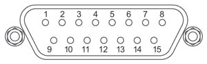
| Pin | Description | Pin | Description |
|---|---|---|---|
| 1 | Quadrature A- | 9 | Ground |
| 2 | Quadrature A+ | 10 | Motor Phase C |
| 3 | Quadrature B+ | 11 | Motor Phase A |
| 4 | Quadrature B- | 12 | Motor Phase B |
| 5 | Encoder Index I- | 13 | +5 V |
| 6 | Encoder Index I+ | 14 | Ground |
| 7 | Negative Limit | 15 | Stage ID |
| 8 | Positive Limit |
ソフトウェア
Kinesisバージョン1.14.52
XAバージョン1.0.0
KinesisおよびXAソフトウェアパッケージには、当社のモーションコントローラを制御するためのGUIが含まれています。
下記もご利用いただけます。
- 通信プロトコル

Figure 789AソフトウェアのGUI画面
当社では、様々なモーションコントローラを駆動するためのプラットフォームとして、XAソフトウェアパッケージと、今後段階的に終了していくKinesisソフトウェアパッケージの2種類をご用意しています。Kinesisソフトウェアは、当社の全てのモーションコントロール製品に対応しています。XAソフトウェアは開発者向けに改良されたプラットフォームですが、現在のところ定番のモーションコントロール製品の一部に対応している状況です(製品リストはこちらをご覧ください)。このソフトウェアは、継続して重点的に開発が進められており、最終的には当社の全てのモーションコントロール製品に対応する予定です。XAソフトウェアアプリケーションは、2040年までフルサポートを行います。
Kinesis モーションコントロールソフトウェア
Kinesisソフトウェアでは.NETコントロールを使用できるため、最新のC#、Visual Basic、LabVIEW™、あるいはその他の.NET対応言語を使用してカスタムプログラムを作成することができます。また、.NETフレームワークを使用しないアプリケーション用に、ローレベルのDLLライブラリも付属しています。中央シーケンスマネージャ(Central Sequence Manager)は、当社のすべてのモーションコントロール用ハードウェアの統合と同期をサポートしています。
この共通のソフトウェアプラットフォームにより、1種類のソフトウェアツールを習得するだけで、あらゆるKinesisコントローラを簡単に組み合わせて使用することができます。このように1軸システム用から多軸システム用までのあらゆるコントローラを組み合わせ、それら全てを1台のPCの統合されたソフトウェアインターフェイスから制御できます。
Click to Enlarge
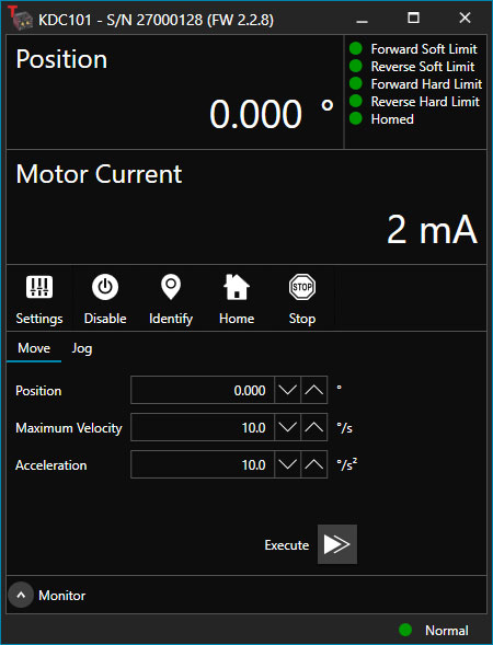
Figure 789B ブラシ付きDCサーボモーターコントローラKDC101用のXA GUI
このソフトウェアパッケージには2つの使い方があります。1つはGUI(グラフィカルユーザーインターフェイス)ユーティリティを用いる方法で、この場合はコントローラの到着後すぐに直接的な操作と制御を行なうことができます。もう1つは一連のプログラミングインターフェイスを用いる方法で、ご希望の開発言語によりカスタム仕様の位置決めやアライメント用のプログラムを簡単に作成することができます。
XAモーションコントロールソフトウェア:開発者向けに改良されたプラットフォーム
XAはその基本から理解しやすいように設計されており、スレッドセーフで言語パラダイムに依存しないC、C++、C#/.NETのアプリケーションプログラミングインターフェイスを提供します。また、ネイティブ、.NET言語、PythonまたはLabVIEWアプリケーションに簡単に統合できる言語ラッパーも用意されています。これは前述のKinesisにおけるソフトウェア開発キット(SDK)と同じ機能を果たす一方で、開発者に対してはより効率化されたツールキットを提供します。このソフトウェアは、付属の開発者用ガイドとSDK内のコード例を組み合わせて、複雑でカスタマイズされたアプリケーションとインターフェースを作成しようとするユーザー向けに設計されています。完全なAPIドキュメントはネイティブCライブラリ用に提供されており、.NETラッパーのドキュメントは現在開発中です。.NETラッパーの詳細については当社までお問い合わせください。
XAはKinesisと同等のGUIを備えているだけでなく、デバイスの状態を保存する機能の追加や、異なる種類のデバイス間インテーフェイスにおける一貫性の向上など、利用者のための様々な改善や工夫が実装されています。Kinesisソフトウェアは段階的に終了となりますが、XAは更に改善を進めるとともに、2040年までフルサポートしていく計画です。現行バージョンのXAソフトウェアは、まだ当社のモーションコントローラの一部にのみ対応している状況です。しかし、このソフトウェアは、継続して重点的に開発が進められており、最終的には当社の全てのモーションコントロール製品に対応する予定です。ソフトウェアの適合性に関する情報は、XAのユーザーガイドに記載されています。また、サポートしているデバイスのリストなど、ソフトウェアのその他の詳細情報はこちらをご覧ください。
| Posted Comments: | |
Leon Su
(posted 2023-10-26 22:10:06.487) Hello!
I have the KBD101 and DDSM100.
I am trying to program C code to control them on a PC. I want to know how to convert the device units to real-world units.
Thanks. do'neill
(posted 2023-10-31 05:43:18.0) Response from Daniel at Thorlabs. There are two ways to do this, you could convert from device units to real world units in your code rather than in the DLL. All the conversions for our communications protocol starting on page 39. For the DDSM100(/M) you will divide the position in device units by 2000 to get the position in real world units. As another way you could use the DLL, in this case you would use the command BMC_GetRealValueFromDeviceUnit() for the KBD101. Damiano Verardo
(posted 2023-09-14 14:03:16.947) Hello,
we are looking forward using the DDS100/M, but the 1 m cable is too short for our application. Are extensions available? Which requirements (e.g. shielding) are needed to buy/assemble one?
Thank you. do'neill
(posted 2023-09-15 07:47:13.0) Response from Daniel at Thorlabs. We do not have a stock cable that will allow you to do this but I will reach out to you to discuss your application with you BRIAN TEY
(posted 2021-12-24 00:55:51.08) Hi, I faced a problem with the DDSM100/M. When I tried to home it using the APT software, I received an error. The details are as follow:
Internal code: 18310705
Description: Hardware Notification/Response
Notes: A notification or response message has been received from a hardware unit. This may be indicative of a hardware fault or illegal command/parameter sent to the hardware.
Extra info: Hardware response code 34002 received from hardware unit SN 67863119 (in response to message ident 0). Response details:- HomingFailed
Any suggestion to fix this issue?
Thank you DJayasuriya
(posted 2022-01-04 09:22:23.0) Thank you for your inquiry. We will get in touch with you directly to trouble shoot your issue. ERIC AGOSTINI
(posted 2021-06-30 04:29:21.33) How many years can THORLABS commit to delivering the DDS100 / M? DJayasuriya
(posted 2021-07-01 05:15:49.0) Thank you for your inquiry. General rule would say 5 years minimum, but typically most of our items has a long life 10+ years. We will get in touch with you directly for any application questions that you might have. David Russell
(posted 2019-11-10 11:17:05.037) M3 tapped holes for end bracket mounting - Dwg shows 12.00 dim mtg surface to holes. Cad model shows 11.75 dim. cwright
(posted 2019-11-21 08:44:07.0) Response from Charles at Thorlabs: Hello David and thank you for contacting us. The DDSM stages contain feet of 0.25 mm height which have been machined into the base plates. This can be seen in the Auto CAD PDF drawing but is not explicitly called out in the dimensions. I believe if you measure the CAD model to the bottom of these feet you will find the measurements are in agreement with the drawing. Aaron Weber
(posted 2019-10-28 09:21:19.413) What is the encoder resolution for this stage? rmiron
(posted 2019-10-28 01:05:48.0) Response from Radu at Thorlabs: Hello Aaron. The encoder resolution for this stage is 500 nm. That information can be found online on page 35 of Kinesis' serial communications protocol's documentation. Len Ness
(posted 2019-04-24 18:08:13.493) The spec's state Horizontal Load Capacity (Max) 1.98lbs. Also the weight of the stage is 1.6lbs. So in an X/Y configuration does this mean you are limited to .38lbs load on the top stage? rmiron
(posted 2019-04-25 04:04:15.0) Response from Radu at Thorlabs: Hello, Len. You are correct. In an XY configuration, the load capacity is only 0.38 lbs. Brushless motor stages are great for applications which require high velocities, but they are not capable of handling very high loads. victor,lorenz
(posted 2017-10-25 21:19:56.627) I already have a DDSM100/M, but still unused. Now, I am willing to use it, but I did not buy the controller KBD101 at that time.
When I bought the DDSM100/M I thought the controller was the same as the controller for PRM1/MZ8, the KDC101, but now I noticed that they have different code number, although the tecnical description seems to be the same.
My question is, are the KBD101 and KDC101 controllers really different? I have the KDC101 and I wonder if I could use it to drive and control the DDSM100/M linear stage. Will it work properly? might I damage the linear stage or the controller?
Thanks,
Victor Lorenz bwood
(posted 2017-10-30 05:20:34.0) Response from Ben at Thorlabs: Thank you for your question. Unfortunately, the brushed DC servo motors controlled by the KBD101 and the direct drive motors controlled the KBD101 are fundamentally different, and as such the controlers are equally different. For example, the KDC101 has a peak current output of ~250 mA, while the KBD101 outputs the 2A needed by direct drive stages. As such, there is no way to adapt a KDC101 to run a DDSM100/M. ac2021
(posted 2016-08-30 07:33:54.227) We bought the DDSM/100M stage with K-Cube controller KBD101 and none of these appear in the APT software or Kinesis software. Could you help me troubleshooting this as it seems I'm not the only person in this situation? Cheers bhallewell
(posted 2016-08-31 05:29:42.0) Response from Ben at Thorlabs: Hi Alexandre, thank you for getting in touch with us. I will contact you to troubleshoot this with you. martin.kozak
(posted 2016-08-25 15:05:53.43) We bought the stage DDSM100/M with the KBD101 K-Cube driver. The APT software does not work. In the configuration utility it is not possible to choose our stage because it does not offer any motor to choose. It displays an internal error 13520709, MG17core.dll. Also the user interface of APT does not detect any device. Kinesis software works. In future we would like to control the stage via Matlab software. Can you also send me the initialization, home and absolute move dlls with a sample code? Thanks bwood
(posted 2016-08-26 05:43:33.0) Response from Ben at Thorlabs: I am sorry to hear about your problems here. Your local technical support office will be contacting you directly to troubleshoot this issue. We do have a APT and Matlab guide available, and we will also be sending you this document. alfred
(posted 2016-08-17 10:19:16.487) Dear Sir:
I come from Chroma ATE Inc.
I have some question for this Controllor Type:DDSM100/M Compact 100 mm Travel Direct Drive Stage With KBD101 K-Cube Brushless DC Servo Driver.
Please provide
1.Initialization
2.Home
3.Absolute Move
function
Dll and Sample Code to me msoulby
(posted 2016-08-18 07:49:14.0) Response from Mike at Thorlabs: We will contact you directly with more information about our motion control software package. alfred
(posted 2016-08-17 10:02:55.063) Control Type:DDSM100/M Compact 100 mm Travel Direct Drive Stage With KBD101 K-Cube Brushless DC Servo Driver
Please provide
1.Init
2.Home
3.Absolute Move
function Sample Code to me joshua.hendrickson.4
(posted 2016-07-06 10:35:11.03) Can the DDSM100 be controlled with the BBD201? bhallewell
(posted 2016-07-07 11:27:29.0) Response from Ben at Thorlabs: The DDSM100 cannot be driven by the BBD201 due to the cabling format not matching between these two devices. The output current of the BBD201 far exceeds the maximum limits for the DDSM100 motor. delphine.descloux
(posted 2015-12-10 17:18:08.82) Hi,
I have a question about TBD001 brushless servo controller and DDSM100 translation stage used together. The default PID settings are not working (the stage is not loaded yet, I plan to use it with less than 250g on it) and I was wondering if there are tables of appropriate settings ?
Thank you in advance. bhallewell
(posted 2015-12-14 03:43:48.0) Response from Ben at Thorlabs: Thank you for your question here. Please see page.14 of the DDSM100 manual. Here we list Recommended Position Loop PID Parameters & instruction for how these can be optimised based on observable characteristics of motion.
http://www.thorlabs.de/thorcat/23100/DDSM100-Manual.pdf
Further reference to Position & Current Loop parameters can be found on pg. 48-52 in the TBD001 manual.
https://www.thorlabs.com/thorcat/23100/TBD001-Manual.pdf vnalla
(posted 2015-11-23 17:20:56.11) My Dc stage is not working (can not connect to the TBD001)after installation of Windows 10, where as piezo stage still can work. besembeson
(posted 2015-12-03 03:18:52.0) Response from Bweh at Thorlabs USA: Our UK division has been in contact with you to resolve. tholste
(posted 2012-07-26 14:49:00.0) A response from Tor at Thorlabs to rbjaculbia: Thank you for your interest in our Direct Drive Stages! For THz-TDS spectroscopy applications, we recommend our Delay Line Kit (http://www.thorlabs.com/NewGroupPage9.cfm?ObjectGroup_ID=5521). The DDS220 used in this kit offers repeatable delay shifts of 0.67 fs; the theoretical sensitivity would be 3.3 fs, given the resolution of the DDSM100. Please contact techsupport@thorlabs.com if you would like more details. rbjaculbia
(posted 2012-07-23 04:12:48.0) Hi,
We are looking to use this as a delay line for THz-TDS spectroscopy. Will this be viable? Thank you. |
電動リニアステージ
電動の直線移動ステージとしては、ピエゾ駆動の20 µm移動ステージからダイレクトドライブ方式の600 mm移動ステージまで、様々な最大移動量の製品をご用意しております。ステージの多くは、それらを用いてXY軸やXYZ軸などの多軸ステージを構築することができます。ファイバ結合用としては、多軸ステージのページをご覧ください。標準の電動ステージを用いるよりも精密な調整が可能です。直線移動ステージのほかに、電動の回転ステージおよびゴニオステージもご用意しております。また手動移動ステージもございます。
ピエゾステージ
これらのステージでは、様々な駆動機構にピエゾ素子が組み込まれています。ステージORIC®シリーズでは、「スティック-スリップ」と呼ばれる摩擦特性を利用したピエゾ慣性アクチュエータが用いられており、それにより長い移動距離が得られています。当社のモジュール式クイック接続型移動ステージXR25シリーズは、同じ原理で動作するピエゾ慣性アクチュエータPIA25で駆動できます。移動ステージNanoflex™シリーズは、手動アクチュエータに加えて標準的なピエゾアクチュエータが用いられています。ステージElliptec®シリーズでは共振ピエゾモータが用いられており、共振に伴うモータ先端の楕円形の動きで可動プラットフォームを押したり引いたりします。Z軸ステージLPS710E/Mにはピエゾ移動に対する機械的な増幅機構が組み込まれており、またそれに適したコントローラが付属しています。
| Piezoelectric Stages | ||||
|---|---|---|---|---|
| Product Family | ORIC® PDXZ1 Closed-Loop 4.5 mm Vertical Stage | ORIC® PD2 Open-Loop 5 mm Stage | ORIC® PDX2 Closed-Loop 5 mm Stage | ORIC® PDX4 Closed-Loop 12 mm Stage |
| Click Photo to Enlarge | 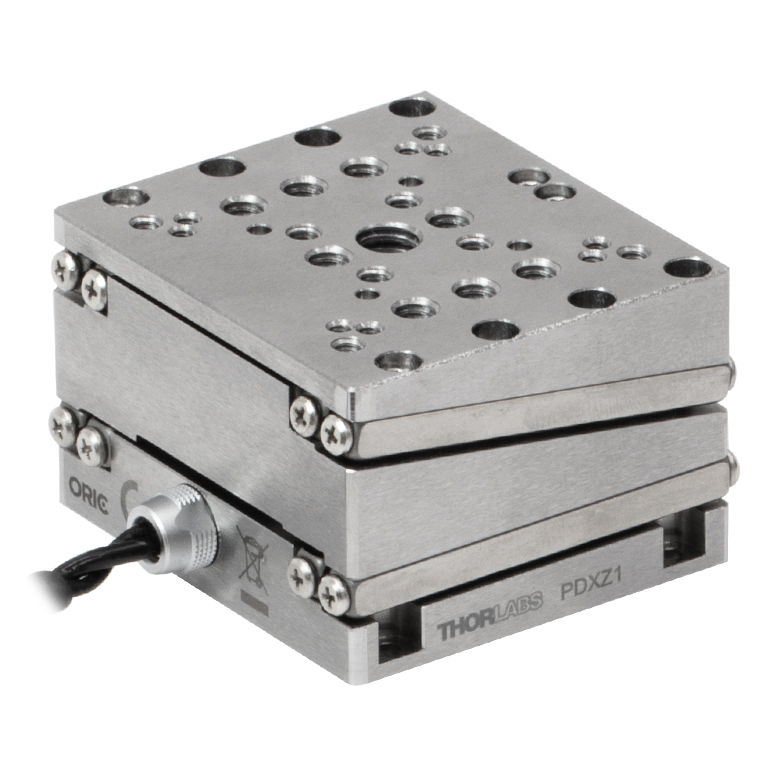 |  |  | 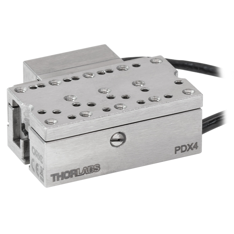 |
| Travel | 4.5 mm | 5 mm | 12 mm | |
| Speed | 1 mm/s (Typ.)a | 10 mm/s (Typ. Max)b | 8 mm/s (Typ.)c | 15 mm/s (Typ.)a |
| Drive Type | Piezoelectric Inertia Drive | |||
| Possible Axis Configurations | Z | X, XY, XYZ | ||
| Mounting Surface Size | 45.0 mm x 42.0 mm | 13.0 mm x 13.0 mm | 13.0 mm x 23.0 mm | |
| Additional Details | ||||
| Piezoelectric Stages | |||||||
|---|---|---|---|---|---|---|---|
| Product Family | ORIC® PD1 Open-Loop 20 mm Stage | ORIC® PD1D Open-Loop 20 mm Monolithic XY Stage | ORIC® PDX1 Closed-Loop 20 mm Stage | ORIC® PD3 Open-Loop 50 mm Stage | Compact Modular XRN25X 25 mm Stage | Modular XR25X 25 mm Stage | |
| Click Photo to Enlarge | 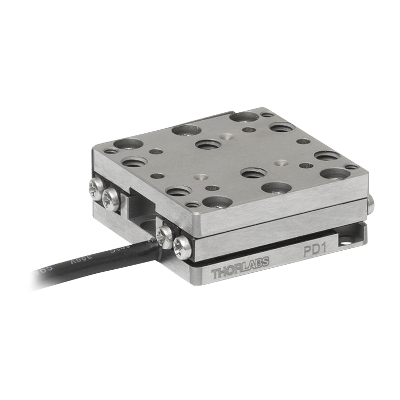 | 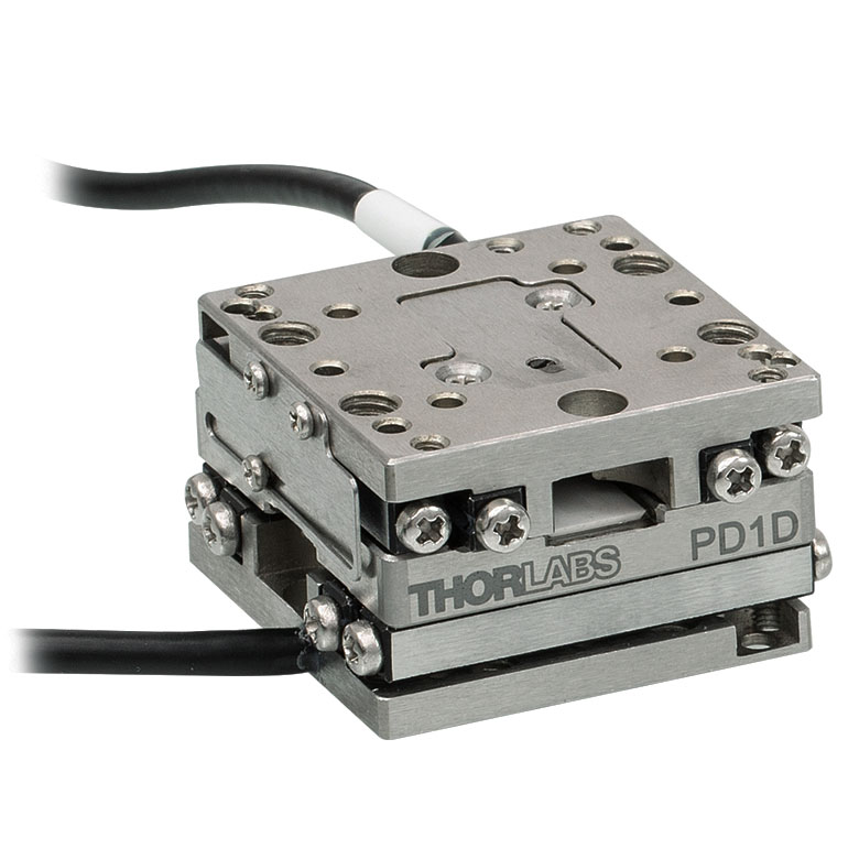 | 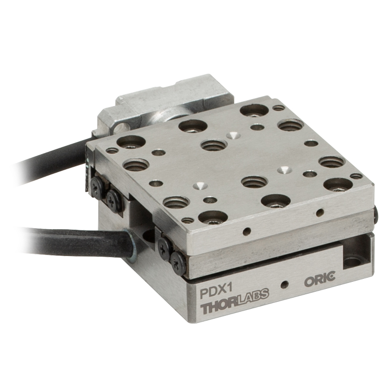 |  |  |  | |
| Travel | 20 mm | 50 mm | 25 mm | ||||
| Speed | 3 mm/s (Typ. Max)a | 20 mm/s (Typ. Max)b | 10 mm/sc | ≤3.6 mm/mind | ≤3.6 mm/mind | ||
| Drive Type | Piezoelectric Inertia Drive | ||||||
| Possible Axis Configurations | X, XY, XYZ | XY, XYZ | X, XY, XYZ | X, XY, XYZ | X, XY, YZ, XZ, XYZ | ||
| Mounting Surface Size | 30.0 mm x 30.0 mm | 80.0 mm x 30.0 mm | 85.0 mm x 50.7 mm | 110.0 mm x 75.7 mm | |||
| Additional Details | |||||||
| Piezoelectric Stages | ||||||
|---|---|---|---|---|---|---|
| Product Family | Nanoflex™ 20 µm Stage with 5 mm Actuator | Nanoflex™ 25 µm Stage with 1.5 mm Actuator | Elliptec® 28 mm Stage | Elliptec® 60 mm Stage | LPS710E 1.1 mm Vertical Stage | |
| Click Photo to Enlarge | 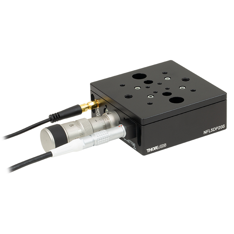 | 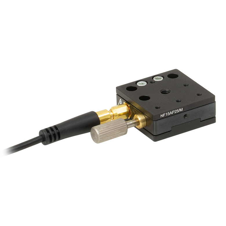 | 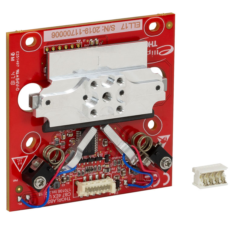 | 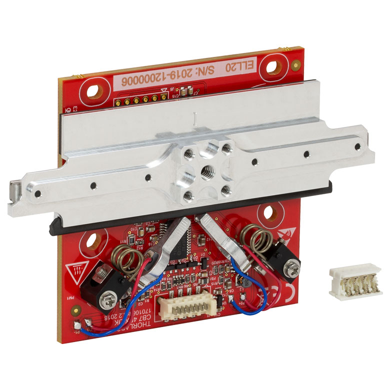 | 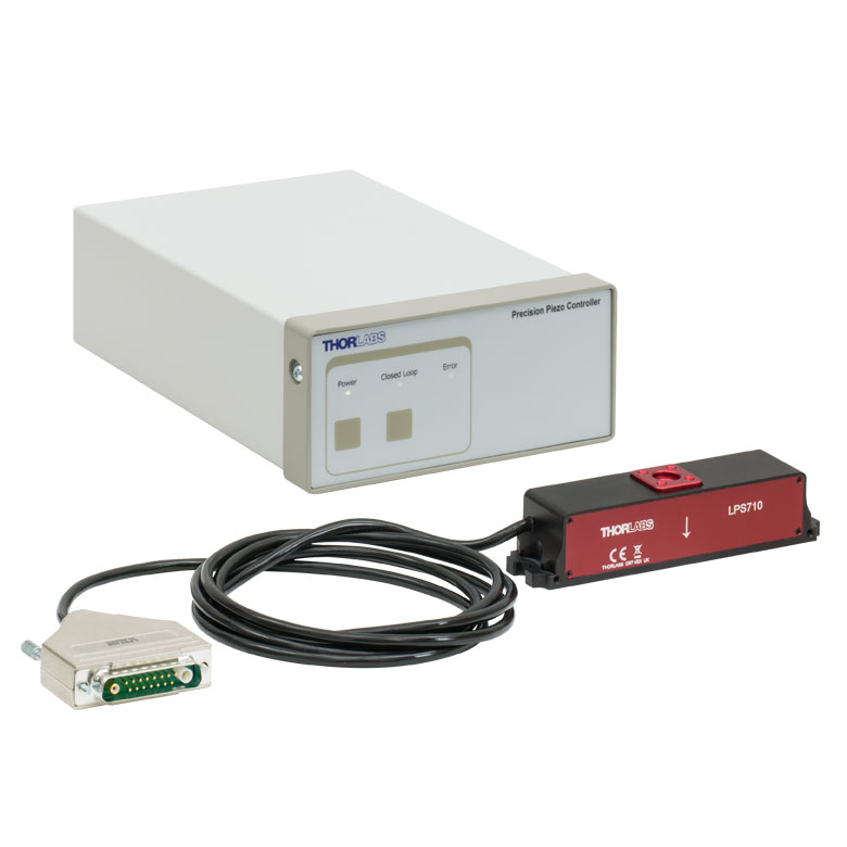 | |
| Travel | 20 µm + 5 mm Manual | 25 µm + 1.5 mm Manual | 28.0 mm | 60.0 mm | 1.1 mm | |
| Speed | - | 180 mm/s (Max) | 90 mm/s (Max) | - | ||
| Drive Type | Piezo with Manual Actuator | Resonant Piezoelectric Motor | Amplified Piezo | |||
| Possible Axis Configurations | X, XY, XYZ | X | Z | |||
| Mounting Surface Size | 75.0 mm x 75.0 mm | 30.0 mm x 30.0 mm | 15.0 mm x 15.0 mm | 21.0 mm x 21.0 mm | ||
| Additional Details | ||||||
ステッピングモーターステージ
こちらの移動ステージは脱着型あるいは内蔵型のステッピングモータを用いており、また300 mmまでの長い移動量が可能です。これらのステージの多くは多軸移動機能を有していたり(PLSXY)、あるいは多軸ステージを組み立てることが可能であったりします(PLSX、クイック接続型XR25シリーズ、LNRシリーズ、NRTシリーズ、LTSシリーズ)。ステージMLJ150/Mは高荷重にも対応する垂直移動ステージです。
| Stepper Motor Stages | |||||
|---|---|---|---|---|---|
| Product Family | MVSN1(/M) 13 mm Vertical Stage | PLS Series 1" Stages | Modular XR25 Series 25 mm Stage | LNR Series 25 mm Stage | LNR Series 50 mm Stage |
| Click Photo to Enlarge | 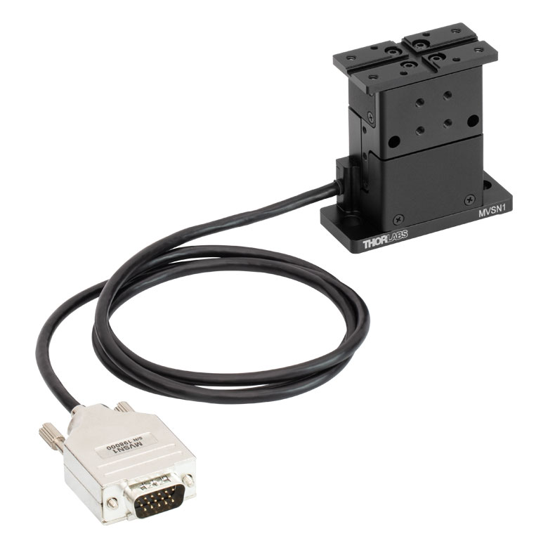 |  | 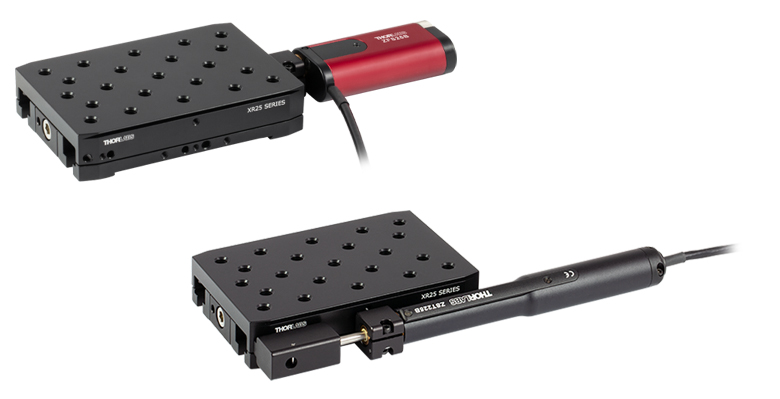 | 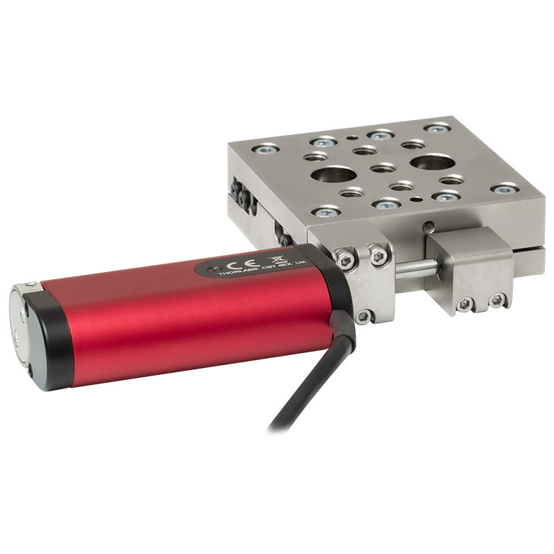 | 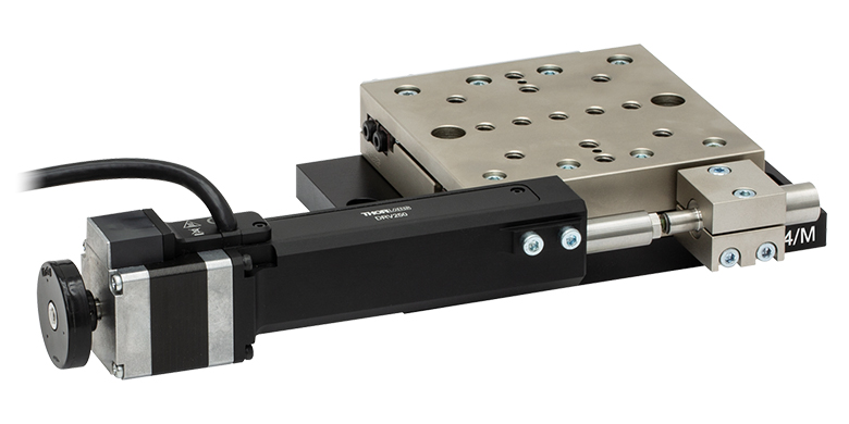 |
| Travel | 13 mm | 1" (25.4 mm) | 25 mm | 25 mm | 50 mm |
| Maximum Velocity | 5.0 mm/s | 7.0 mm/s | 2.0 mm/s | 2.0 mm/s | 50 mm/s |
| Possible Axis Configurations | Z | X, XY | X, XY, YZ, XZ, XYZ | X, XY, XYZ | X, XY, XYZ |
| Mounting Surface Size | 24.5 mm x 50.0 mm | 3" x 3" (76.2 mm x 76.2 mm) | 110.0 mm x 75.7 mm | 60 mm x 60 mm | 100 mm x 100 mm |
| Additional Details | |||||
| Stepper Motor Stages | ||||||
|---|---|---|---|---|---|---|
| Product Family | NRT Series 100 mm Stage | NRT Series 150 mm Stage | LTS Series 150 mm Stage | LTS Series 300 mm Stage | MLJ250 50 mm Vertical Stage | |
| Click Photo to Enlarge |  | 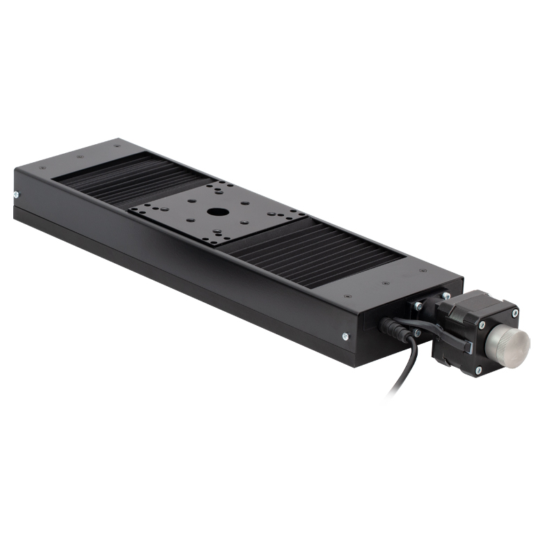 | 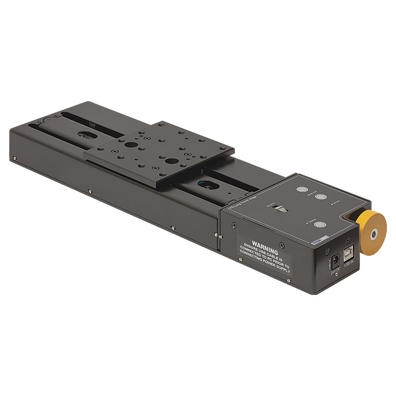 |  | 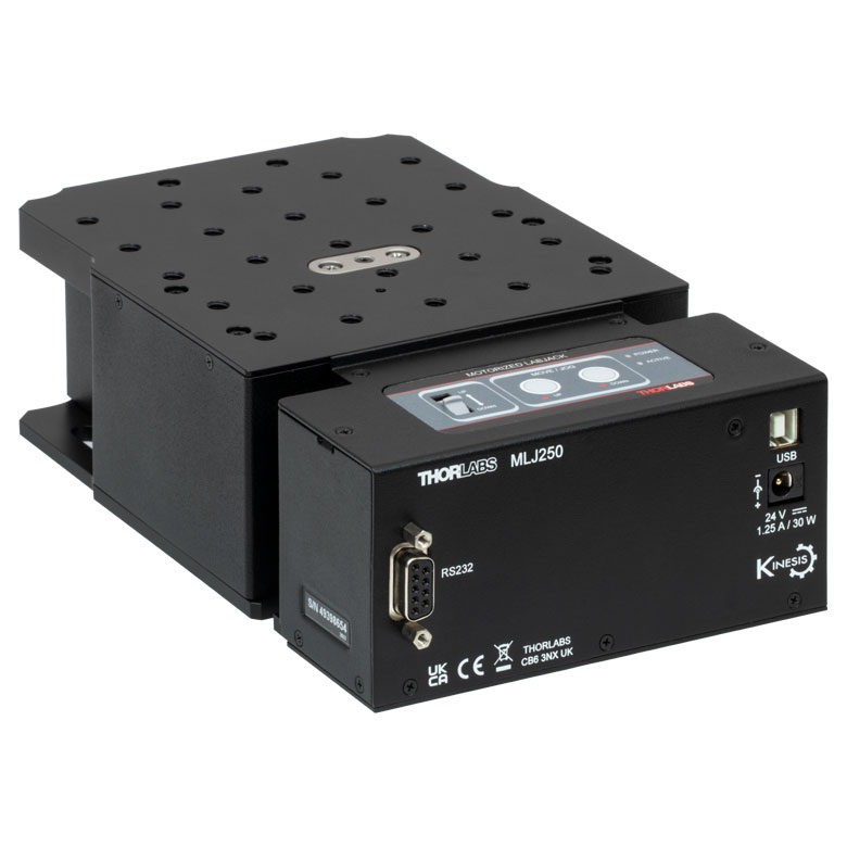 | |
| Travel | 100 mm | 150 mm | 150 mm | 300 mm | 50 mm | |
| Maximum Velocity | 30 mm/s | 50 mm/s | 3.0 mm/s | |||
| Possible Axis Configurations | X, XY, XYZ | X, XY, XYZ | Z | |||
| Mounting Surface Size | 84 mm x 84 mm | 100 mm x 90 mm | 148 mm x 131 mm | |||
| Additional Details | ||||||
DCサーボモーターステージ
脱着型あるいは内蔵型のDCサーボモータを用いた直線移動ステージをご用意しております。これらのステージは薄型で、多軸ステージの構築が可能です。
| DC Servo Motor Stages | ||||||
|---|---|---|---|---|---|---|
| Product Family | MT Series 12 mm Stages | PT Series 25 mm Stages | Compact Modular XNR25X 25 mm Stage | Modular XR25X 25 mm Stage | M30 Series 30 mm Stage | M30 Series 30 mm Monolithic XY Stage |
| Click Photo to Enlarge |  |  | 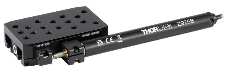 | 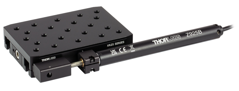 |  | 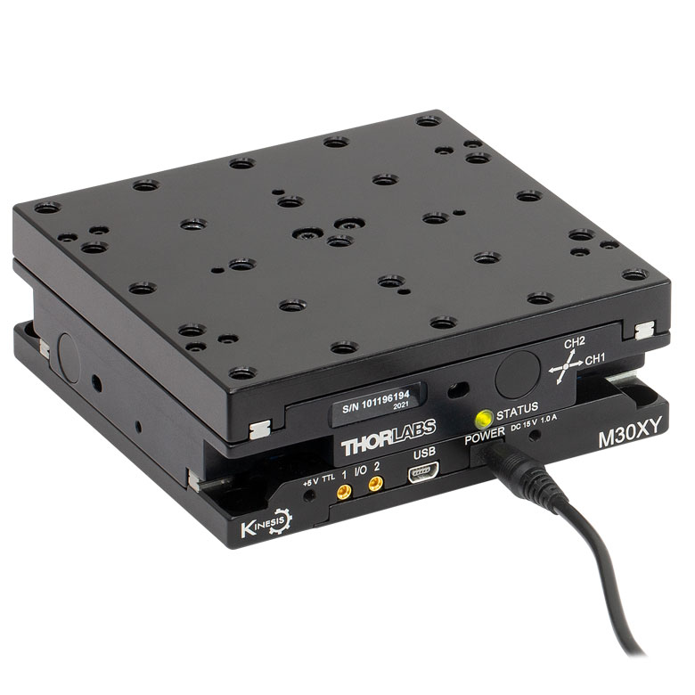 |
| Travel | 12 mm | 25 mm | 25 mm | 30 mm | ||
| Max Speed | 2.6 mm/s | 2.6 mm/sa | 2.4 mm/s | |||
| Possible Axis Configurations | X, XY, XYZ | X, XY, YZ, XZ, XYZ | X, Z | XY, XZ | ||
| Mounting Surface Size | 61.0 mm x 61.0 mm | 101.6 mm x 76.2 mm | 85.0 mm x 50.7 mm | 110.0 mm x 75.7 mm | 115.0 mm x 115.0 mm | |
| Additional Details | ||||||
| DC Servo Motor Stages | |||||
|---|---|---|---|---|---|
| Product Family | MTS Series 25 mm Stage | MTS Series 50 mm Stage | MTS Series 100 mm Stage | M150 Series 150 mm XY Stage | KVS30 30 mm Vertical Stage |
| Click Photo to Enlarge | 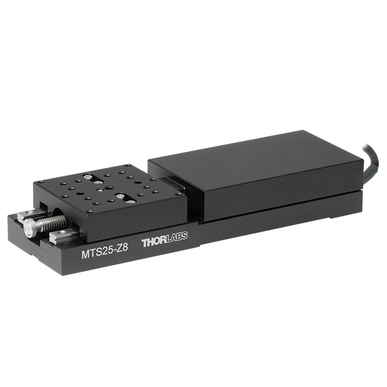 | 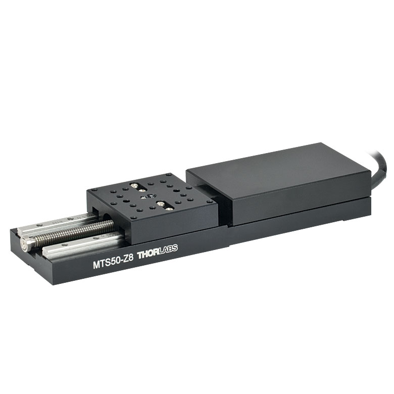 | 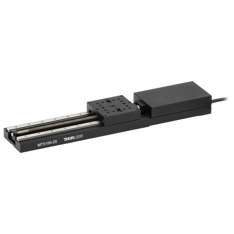 | 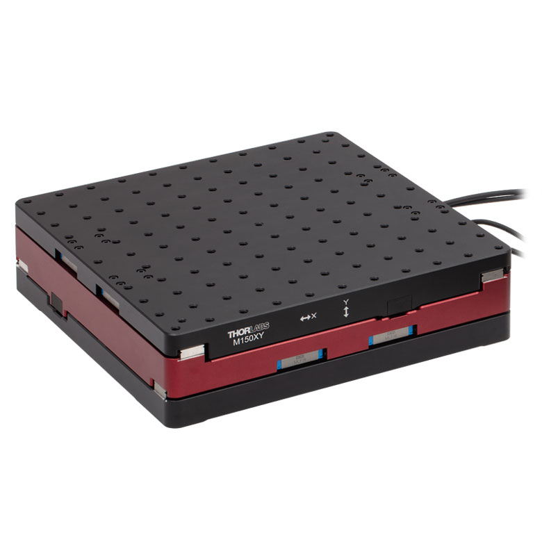 |  |
| Travel | 25 mm | 50 mm | 100 mm | 150 mm | 30 mm |
| Max Speed | 2.4 mm/s | X-Axis: 170 mm/s Y-Axis: 230 mm/s | 8.0 mm/s | ||
| Possible Axis Configurations | X, XY, XYZ | XY | Z | ||
| Mounting Surface Size | 43.0 mm x 43.0 mm | 272.4 mm x 272.4 mm | 116.2 mm x 116.2 mm | ||
| Additional Details | |||||
ダイレクトドライブステージ
こちらの薄型ステージにはブラシレスDCサーボモータが内蔵されており、バックラッシュの無い高速移動が可能です。電源が入ってないときは、ステージのプラットフォームにはほとんど慣性が無く、実質的にフリーラン状態になります。そのため電源が入ってないときにステージのプラットフォームが定位置に留まる必要のある用途には適していません。これらのステージを垂直方向に取付けることは推奨しません。
| Direct Drive Stages | |||||
|---|---|---|---|---|---|
| Product Family | DDS Series 50 mm Stage | DDS Series 100 mm Stage | DDS Series 220 mm Stage | DDS Series 300 mm Stage | DDS Series 600 mm Stage |
| Click Photo to Enlarge | 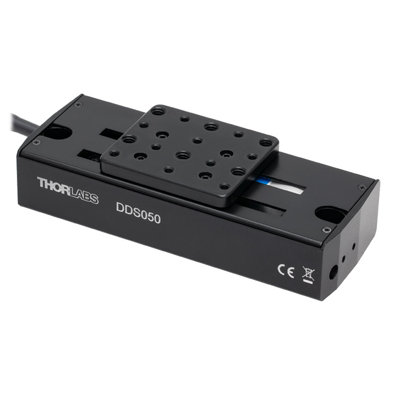 | 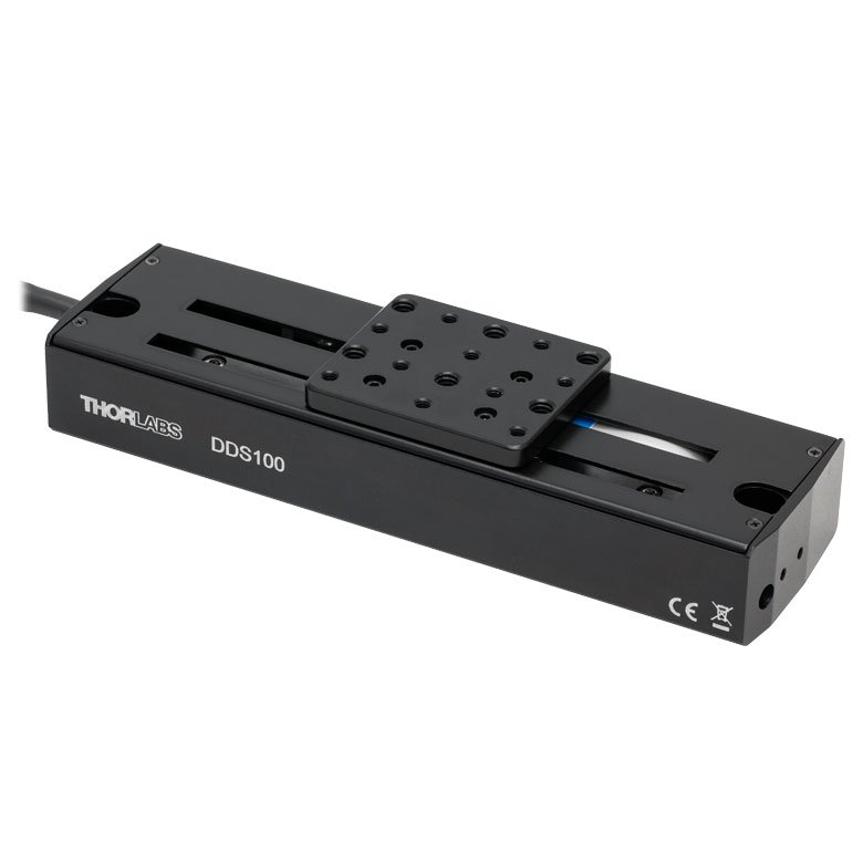 | 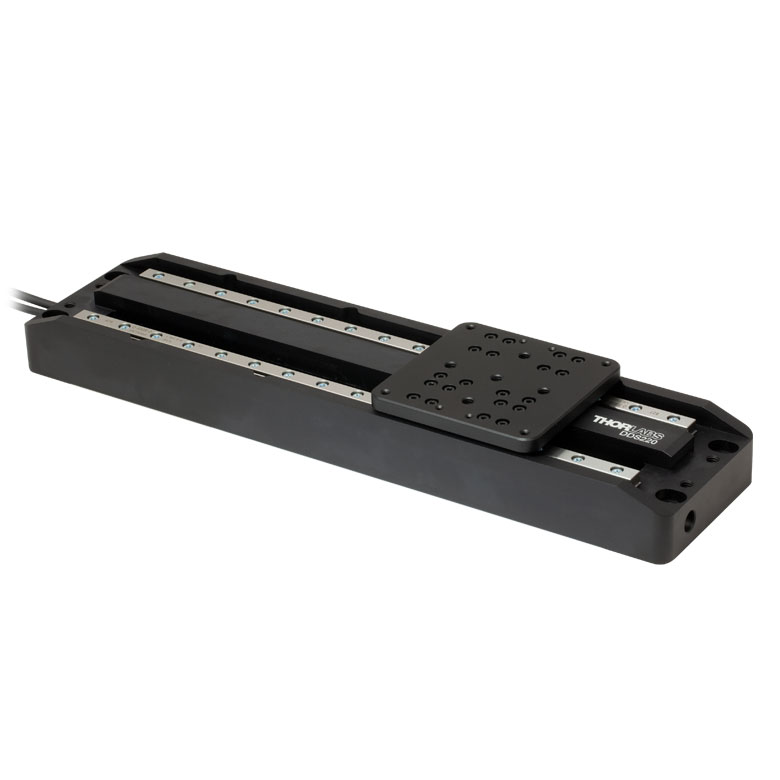 | 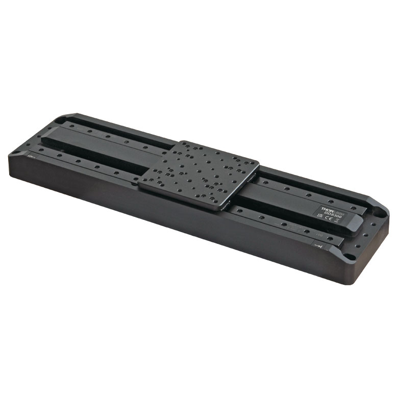 |  |
| Travel | 50 mm | 100 mm | 220 mm | 300 mm | 600 mm |
| Maximum Velocity | 500 mm/s | 300 mm/s | 400 mm/s | 400 mm/s | |
| Possible Axis Configurations | X, XY | X, XY | X | X | |
| Mounting Surface Size | 60 mm x 52 mm | 88 mm x 88 mm | 120 mm x 120 mm | ||
| Additional Details | |||||

 ズーム
ズームステージDDS100/Mは高速移動と高い位置確度が特長で、データを収集しながら同時にカメラやプローブを一定の速度で移動させる必要がある表面のマッピングや解析用途に適しています。 安定した閉ループ制御システムとコントローラKBD101を組合わせることによって、正確で微細な位置決めと制御が可能となります。
注:磁性部品はステージのプラットホーム上には取り付けないでください。磁石によりホーミングが正確に動作しなくなり、磁性部品を取り外した後もステージのエンコーダの精度に影響を及ぼす可能性があります。これらのステージは垂直方向(Z軸)の動作には適しておりませんのでご注意ください。電源が入ってないときのプラットフォームはロックされていない状態(フリーラン状態)になります。 そのため電源が入ってないときに定位置に留まる必要のある用途には適していません。
")
 ズーム
ズーム
Click to Enlarge
アダプタープレートDDSMA1(/M)およびDDSMA2(/M)を使用すると、ステージDDS100(/M)の移動部に近接してオプトメカニクス部品を取り付けることができます。
Click for Details
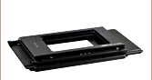
XYアダプタープレートDDSMP1(/M)を使用すると、ステージDDS100(/M)を2つ用いてXYステージを構成できます。
2軸構成が必要な場合には、右の写真のようにアダプタープレートDDSMP1/Mを用いて2つのステージDDS100/Mをボルトで固定し、XYステージを構成できます。
アダプタープレートDDSMA1/MおよびDDSMA2/Mは、付属のM3 x 20ネジ2個を使用してステージDDS100/Mの端部に取り付けられます(右の写真参照)。アダプタープレートを利用すると、ディレイラインを構成するときのように、直線移動するステージに近接してオプトメカニクス部品を取付けることができます。プレートには6つのM6 x 1.0タップ穴と5つのM4 x 0.7タップ穴があります。

 ズーム
ズーム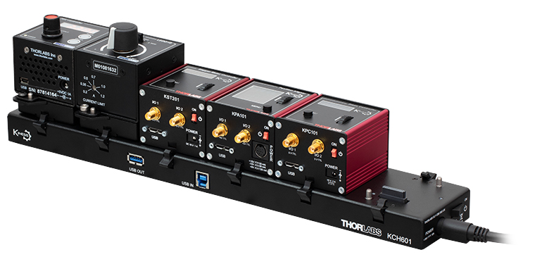
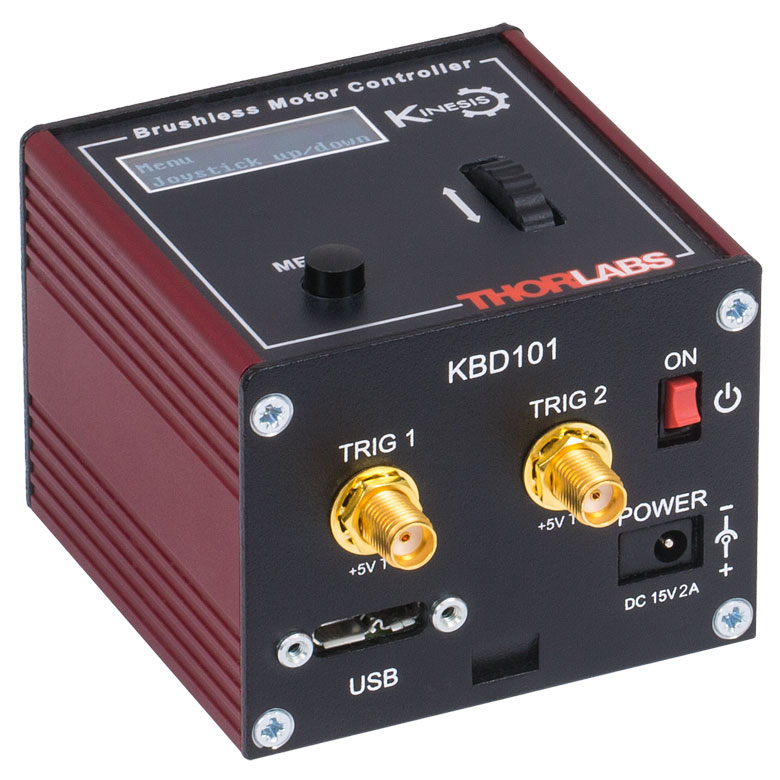
- 前面パネルに電動ステージやアクチュエータ制御用の速度ホイールとデジタル表示画面
- 2つの双方向SMCトリガーポート(外部機器からの信号読み取りや外部機器の制御用)
- 付属のUSBケーブルでPCに接続
- KinesisおよびXAソフトウェアに完全対応
- コンパクトな設置面積:60 mm x 60 mm x 49.2 mm
- 電源は付属しません(下記参照)
K-Cube®ブラシレスDCモーターコントローラKBD101は、1台のモータの回転軸を手動またはPCで制御します。上面のコントロールパネルには速度ホイールがあり、位置のプリセットに加えて、順方向ならびに逆方向のジョグ動作と双方向の4段階速度制御が可能です。上面パネルのデジタル表示にはバックライトが付いており、メニュー選択により暗くしたり消灯したりすることが可能です。ユニット前面には双方向のSMCトリガーポートが2つあり、5 Vの外部ロジック信号を読み取ることや、5 Vロジック信号を出力して外部機器を制御することができます。それぞれのポートの機能は独立に設定することができます。
コントローラKBD101については、当社のKinesisおよびXAの両ソフトウェアがサポートしていますが、XAは現時点ですべてのモーションコントロールデバイスをサポートしているわけではありません。XAがサポートしている製品の一覧は、こちらからご覧いただけます。詳細は「Kinesis & XAソフトウェア」タブをご参照ください。
このコントローラには電源が付属しませんのでご注意ください。対応可能な電源は下記のとおりです。詳細はブラシレスDCサーボモーターコントローラKBD101の製品紹介ページでご覧ください。

 ズーム
ズーム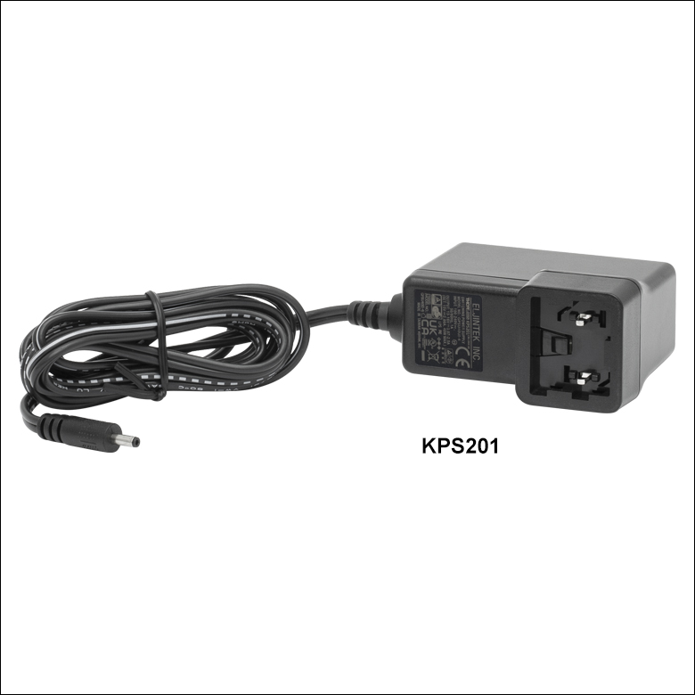
Click to Enlarge
Figure 780A 電源ユニットKPS201(日本国内向けアダプタと共に発送します)
- 電源(単体)
- KPS201: K-Cube®、T-Cubes™ 用、3.5 mmジャック付き
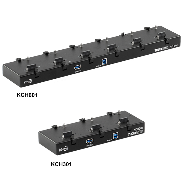
- 電源供給と通信機能を備えたUSBコントローラハブ
- KCH301: 3台までのK-CubeまたはT-Cube用
- KCH601: 6台までのK-CubeまたはT-Cube用
電源KPS201の出力電圧は+15 VDC、最大電流は2.66 Aで、3.5 mmジャックで1台のK-CubeまたはT-Cubeに電力を供給します。標準的な壁コンセントに接続して使用します。
USBコントローラーハブKCH301およびKCH601は次の2つの機能を有しています。1つはハブ機能で、最大3台(KCH301)または6台(KCH601)までのK-CubeまたはT-Cubeをサポートします。もう1つは電源機能で、標準的な壁コンセントに接続するだけで必要な電力の供給を行います。ただし、ハブが供給できる最大電流は10 Aです。お使いになる全Cubeの必要電流が合計で10 A以上にはならないことをお確かめください。 また、このハブに取り付けられたすべてのT-CubeやK-Cubeに対して、1本のUSBケーブルで接続することができます。
USBコントローラハブの詳細は、製品ページをご参照ください。