 Products Home / 自動(電動)ステージ / 電動直線移動ステージ(自動リニアステージ) / 電動直線移動ステージ(リニアステージ):移動量100 mm以上 / 450 mm Linear Translation Stage with Integrated Controller, Stepper Motor
450 mm Linear Translation Stage with Integrated Controller, Stepper Motor
- Integrated Controller with Keypad and Remote USB Control
- Stackable in XY Configurations
- Calibrated On-Axis Accuracy of <±5 µm
- Horizontal Load Capacity of 15 kg (33.1 lbs)
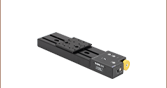
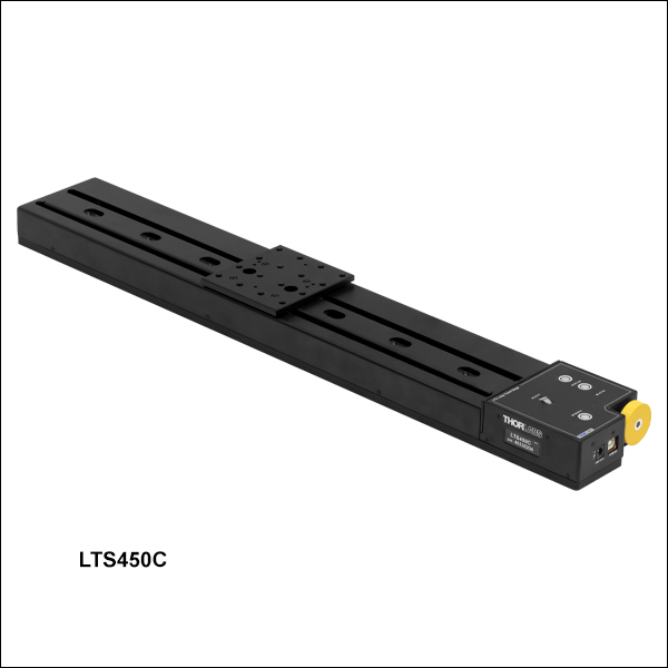
LTS450C
450 mm Translation Stage, 1/4-20 Taps
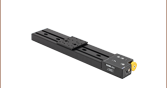
LTS450C/M
450 mm Translation Stage, M6 x 1.0 Taps
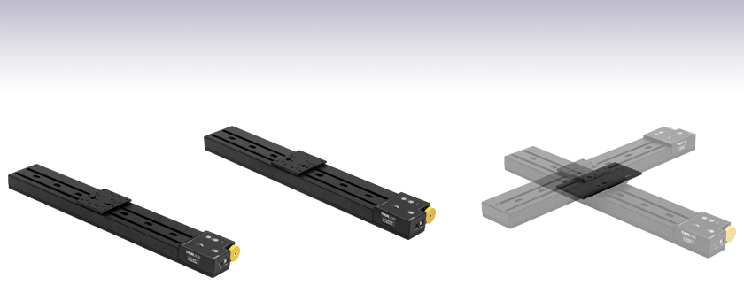
Application Idea
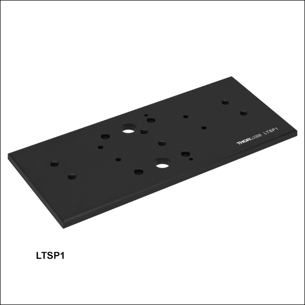
Using the LTSP1 Adapter Plate, two stages can be mounted in an XY Configuration.


Please Wait
| Key Specificationsa | |
|---|---|
| Travel Range | 450.0 mm (17.72") |
| Horizontal Velocity (Max) | 50 mm/s |
| Vertical Velocity (Max) | 3 mm/s |
| Minimum Achievable Incremental Movementb |
0.1 µm |
| Calibrated On-Axis Accuracyc | <±5 µm |
| Bidirectional Repeatabilityd | <±2 µm |
| Backlashe | 2 µm |
| Load Capacity (Max) - Stage Mounted Horizontally |
15 kg (33.1 lbs) |
| Load Capacity (Max) - Stage Mounted Vertically |
4 kg (8.8 lbs) |
| Actuator Type | Stepper Motor |
| Included USB Cable Length | 1.5 m (4.9 ft) |
Features
- 450 mm Travel Range
- Integrated Stepper Motor Controller
- Control via Manual Keypad or Remote PC
- Load Capacity
- Horizontally Mounted: 15 kg (33.1 lbs)
- Vertically Mounted: 4 kg (8.8 lbs)
- Maximum Velocity of 50 mm/s
- Bidirectional Repeatability of <±2 µm
- XYZ Configurable
- Z Axis Configurations are Available when using the LTS450C(/M) as the Base with the LTS150C(/M) or LTS300C(/M) Mounted Vertically
- 1/4"-20 or M6 Tapped Holes for Mounting Standard Optomechanics
- Power Supply Included
Thorlabs' LTS450C(/M) Linear Translation Stage with Integrated Controller is optimized for applications requiring high load capacity and high resolution, such as measurement and inspection. It provides 450 mm of linear travel for loads as great as 15 kg (33.1 lbs) when mounted horizontally and 4 kg (8.8 lbs) when mounted vertically. Each stage features a calibrated on-axis accuracy of <±5 µm when the unit-specific calibration files are used with either the Thorlabs Kinesis or XA software. Due to the stepper motor design, the platform position remains fixed when no power is supplied to the stage, unlike with DC servo motor translation stages.
Click to Enlarge
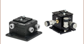
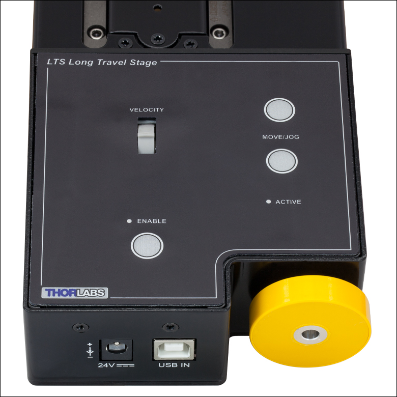
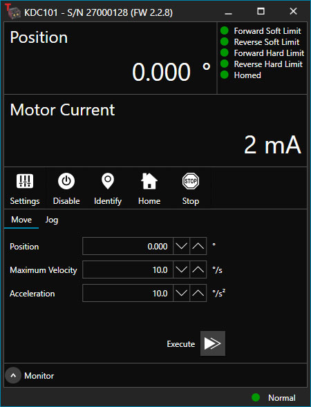
Figure 1.1 Integrated Controller with Manual and Remote PC Control
| Motorized Linear Long-Travel Stages | |
|---|---|
| 100 mm | Stepper |
| DC Servo | |
| 150 mm | Stepper |
| Stepper with Integrated Controller | |
| 220 mm | DC Servo |
| 300 mm | Stepper with Integrated Controller |
| DC Servo | |
| 450 mm | Stepper with Integrated Controller |
| 600 mm | DC Servo |
| Optical Delay Line Kits | |
| Other Translation Stages | |
The LTS450C(/M) stage features an integrated electronic controller that can be controlled remotely using a PC or manually via the buttons and velocity potentiometer on the control keypad (see Figure 1.1). Parameter settings can be adjusted on the PC and stored in non-volatile memory within the unit itself. When the unit is powered up, these settings are applied automatically. This is particularly useful when the stage is being used manually in the absence of a PC and USB link.
The stage is lightweight, compact, and robust with high performance over the full travel range. The heavy-duty aluminum construction and 6.0 mm moving platform height makes this stage ideal for applications where space is limited. Integrated magnetic limit switches allow homing and overdrive protection in both directions. A precision-ground lead screw delivers smooth, virtually noise-free movement. The power supply provided with the stage operates with 90 - 264 VAC input voltages (47 - 63 Hz) and is shipped with a location-specific power cord.
Thorlabs also offers the LTS150C(/M) and LTS300C(/M) Linear Translation Stages with Integrated Controllers, which feature 150 mm or 300 mm of travel, respectively.
Calibration Files
Each LTS450C(/M) Linear Translation Stage is calibrated during manufacturing. Calibration enables the controller to correct for any mechanical errors present in the system. Mechanical components, such as the lead screw and linkages, can be machined only within a certain tolerance. These mechanical errors result in deviations of the actual position from the commanded position. However, the deviations are repeatable and can be compensated for using the Kinesis or XA software and included calibration files. These files are used by the software to convert the position entered by the user into the required mechanical motion. The calibration files can be downloaded by clicking on the red Docs icon  )
)
The use of calibration files is optional. Without them, the repeatability and resolution of the stage are unaffected, but no compensations are made to enhance the accuracy. Each stage is calibrated at the factory, giving a typical on-axis accuracy of 47 µm without the use of the calibration files.
Stage Combinations
If an XY configuration is desired, any combination of LTS150C(/M), LTS300C(/M), and LTS450C(/M) Linear Positioning Stages (featuring a 150 mm, 300 mm, or 450 mm travel range, respectively) can be mounted atop one another using the LTSP1(/M) XY Adapter Plate (sold below). XZ and XYZ configurations for the LTS150C(/M) and LTS300C(/M) stages are possible using our LTSP3(/M) Z-Axis Bracket, which orients the stage in the vertical plane. Please note that stages and adapters with imperial or metric taps are only compatible with other stages and adapters featuring the same thread standards.
Software
Thorlabs offers the Kinesis® and XA software packages to drive our wide range of motion controllers, including our multi-channel controllers, rack-based controller, and smaller, optical-table-mountable K-Cube® controllers. This single unified software offering allows seamless mixing of the LTS450C(/M) stages with any benchtop, tabletop, or rack-based controllers.
| Stage Specifications | ||
|---|---|---|
| Translation | ||
| Travel Range | 450 mm (11.8") | |
| Bidirectional Repeatability | <±2 µm | |
| Backlash | 2 µm | |
| Maximum Velocitya | 50 mm/s Horizontal, 3 mm/s Vertical | |
| Velocity Stability | ±1 mm/s | |
| Maximum Accelerationa | 35 mm/s2 Horizontal, 5 mm/s2 Vertical | |
| Accuracy | ||
| Min Achievable Incremental Movementb | 0.1 µm | |
| Min Repeatable Incremental Movementc | 4 µm | |
| Calibrated On-Axis Accuracy | <±5 µm | |
| Home Location Accuracy | ±0.6 µm | |
| Pitchd | <0.0096° (168 µrad) | |
| Yawd | <0.0058° (101 µrad) | |
| Load Capacity | ||
| Horizontal Load Capacity | Max: 15 kg (33.1 lbs) Recommended: <12 kg (26.5 lbs) |
|
| Vertical Load Capacity | Max: 4 kg (8.8 lbs) | |
| General | ||
| Included USB Cable Length | 1.5 m (4.9 ft) USB Type-B to Type-A Cable | |
| Weight | 4.8 kg (10.58 lbs) | |
| Dimensions (W x D x H) | 100.0 mm x 660.0 mm x 45.5 mm (3.94" x 25.98" x 1.79") |
|
| Electrical Specifications | |
|---|---|
| Motor Specifications | |
| Step Angle | 1.8° (50 Poles and ±2 Phases for 360° Divided by 200) |
| Step Accuracy | 5% |
| Rated Phase Current | 0.85 A |
| Phase Resistance | 5.4 Ω |
| Phase Inductance | 5.6 mH |
| Holding Torque | 20 N•cm |
| Detent Torque | 2.0 N•cm |
| Operating Temperature | -20 to 40 °C (Motor Specification Only) |
| Controller Specifications | |
| Microsteps per Full Step | 2048 |
| Microsteps per Revolution of Motor | 409,600 (for 200 Step Motor) |
| Motor Drive Voltage | 24 V |
| Motor Drive Power | 12.5 W (Avg.) Up to 25 W (Peak) |
| Motor Speed | Up to 3000 RPM (200 Full Step Motor) |
| Input Power Requirements | |
| Voltage | 24 VDC |
| Power | 25 W (Peak) / 12.5 W (Avg) |
| Power Supply Requirements | 90 - 264 VAC (47 - 63 Hz) |
Notes
電動リニアステージ
電動の直線移動ステージとしては、ピエゾ駆動の20 µm移動ステージからダイレクトドライブ方式の600 mm移動ステージまで、様々な最大移動量の製品をご用意しております。ステージの多くは、それらを用いてXY軸やXYZ軸などの多軸ステージを構築することができます。ファイバ結合用としては、多軸ステージのページをご覧ください。標準の電動ステージを用いるよりも精密な調整が可能です。直線移動ステージのほかに、電動の回転ステージおよびゴニオステージもご用意しております。また手動移動ステージもございます。
ピエゾステージ
これらのステージでは、様々な駆動機構にピエゾ素子が組み込まれています。ステージORIC®シリーズでは、「スティック-スリップ」と呼ばれる摩擦特性を利用したピエゾ慣性アクチュエータが用いられており、それにより長い移動距離が得られています。移動ステージNanoflex™シリーズは、手動アクチュエータに加えて標準的なピエゾアクチュエータが用いられています。ステージElliptec®シリーズでは共振ピエゾモータが用いられており、共振に伴うモータ先端の楕円形の動きで可動プラットフォームを押したり引いたりします。Z軸ステージLPS710E/Mにはピエゾ移動に対する機械的な増幅機構が組み込まれており、またそれに適したコントローラが付属しています。
| Piezoelectric Stages | ||||||
|---|---|---|---|---|---|---|
| Product Family | ORIC® PDXZ1 Closed-Loop 4.5 mm Vertical Stage | ORIC® PD2 Open-Loop 5 mm Stage | ORIC® PDX2 Closed-Loop 5 mm Stage | ORIC® PDX4 Closed-Loop 12 mm Stage | ORIC® PD1 Open-Loop 20 mm Stage | ORIC® PD1D Open-Loop 20 mm Monolithic XY Stage |
| Click Photo to Enlarge | 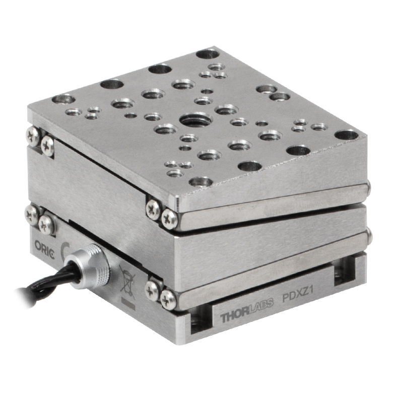 |  |  | 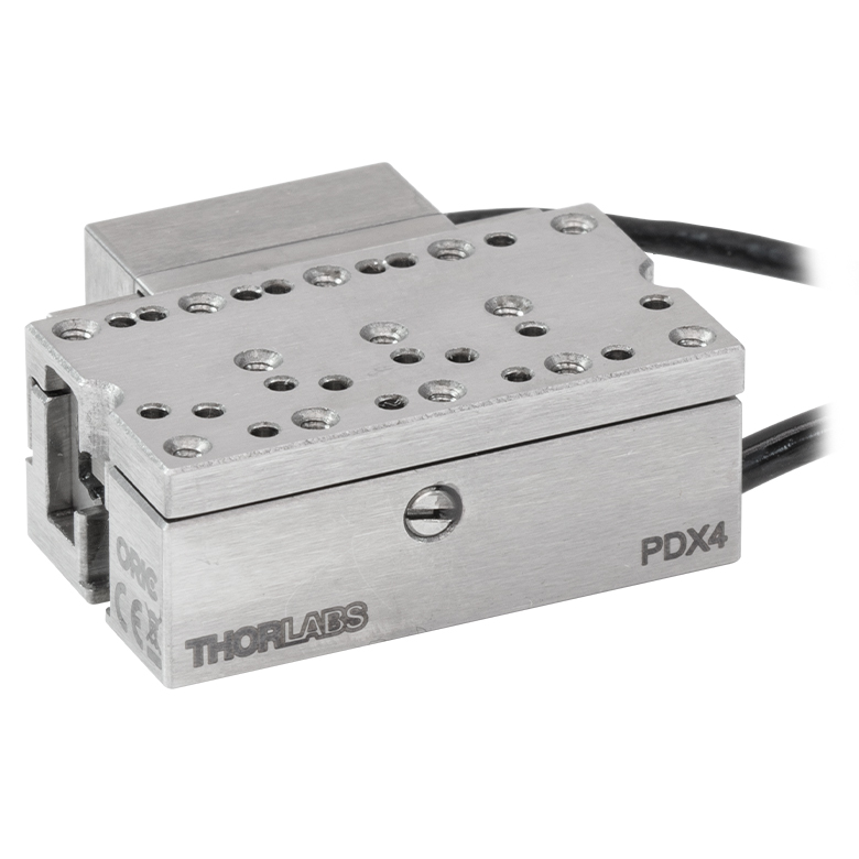 | 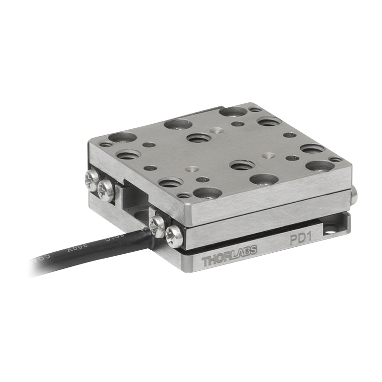 | 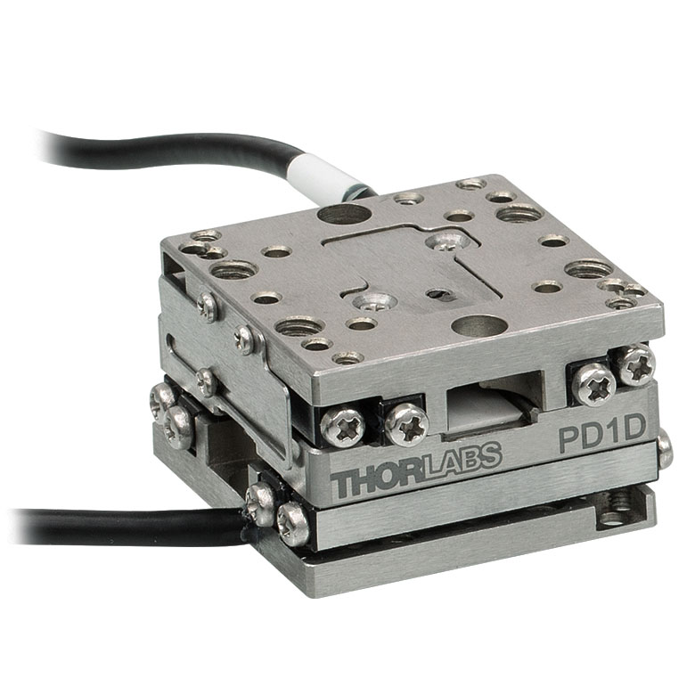 |
| Travel | 4.5 mm | 5 mm | 12 mm | 20 mm | ||
| Speed | 1 mm/s (Typ.)a | 10 mm/s (Typ. Max)b | 8 mm/s (Typ.)c | 15 mm/s (Typ.)a,c | 3 mm/s (Typ. Max)d | |
| Drive Type | Piezoelectric Inertia Drive | |||||
| Possible Axis Configurations | Z | X, XY, XYZ | XY, XYZ | |||
| Mounting Surface Size | 45.0 mm x 42.0 mm | 13.0 mm x 13.0 mm | 13.0 mm x 23.0 mm | 30.0 mm x 30.0 mm | ||
| Additional Details | ||||||
| Piezoelectric Stages | ||||||
|---|---|---|---|---|---|---|
| Product Family | ORIC® PDX1 Closed-Loop 20 mm Stage | ORIC® PDX1A Closed-Loop 20 mm Stage Low-Profile | ORIC® UDX1 Ultrasonic Closed-Loop 20 mm Stage | ORIC® PD3 Open-Loop 50 mm Stage | ORIC® PDX3 Closed-Loop 50 mm Stage | |
| Click Photo to Enlarge | 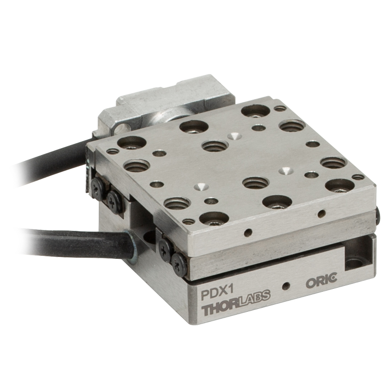 | 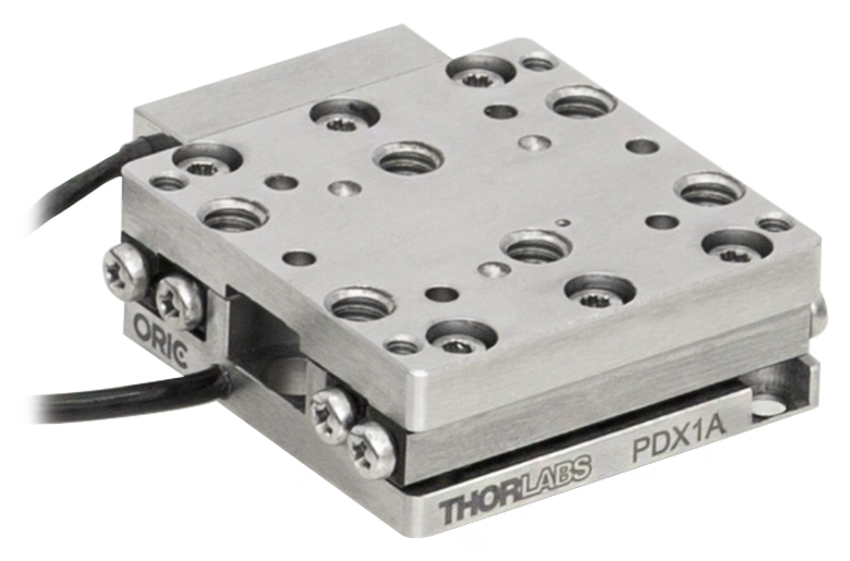 | 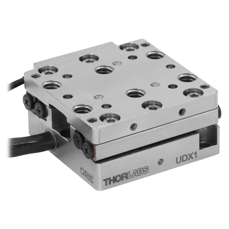 |  |  | |
| Travel | 20 mm | 50 mm | ||||
| Speed | 20 mm/s (Typ. Max)a | 10 mm/s (Typ.)b | 100 mm/s (Typ. Max)c | 10 mm/sd | 10 mm/s (Typ. Max)b | |
| Drive Type | Piezoelectric Inertia Drive | Ultrasonic Piezoelectric Drive | Piezoelectric Inertia Drive | |||
| Possible Axis Configurations | X, XY, XYZ | |||||
| Mounting Surface Size | 30.0 mm x 30.0 mm | 80.0 mm x 30.0 mm | ||||
| Additional Details | ||||||
| Piezoelectric Stages | |||||||
|---|---|---|---|---|---|---|---|
| Product Family | Nanoflex™ 20 µm Stage with 5 mm Actuator | Nanoflex™ 25 µm Stage with 1.5 mm Actuator | Compact Modular XRN25X 25 mm Stage | Modular XR25X 25 mm Stage | Elliptec® 28 mm Stage | Elliptec® 60 mm Stage | LPS710E 1.1 mm Vertical Stage |
| Click Photo to Enlarge | 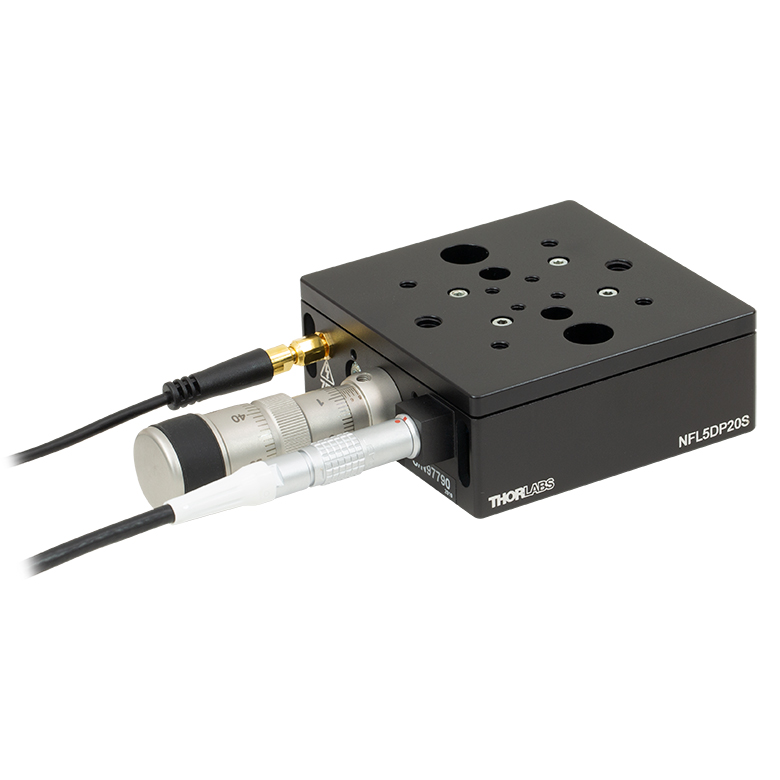 | 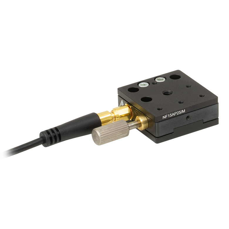 |  |  | 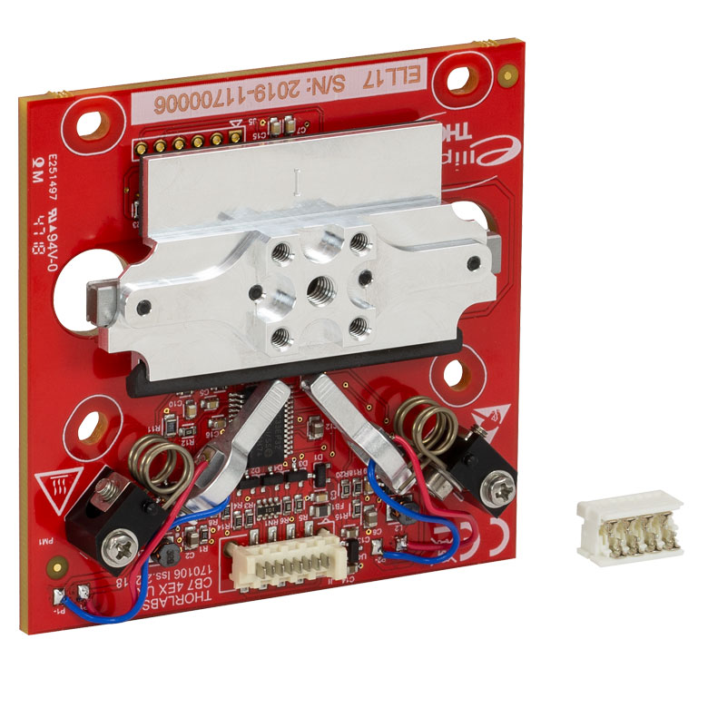 | 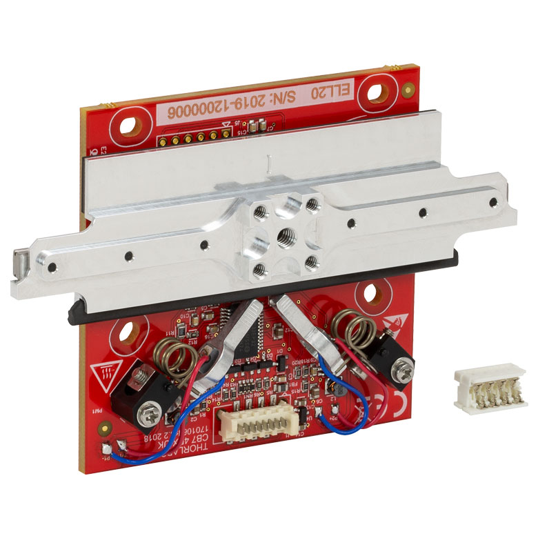 | 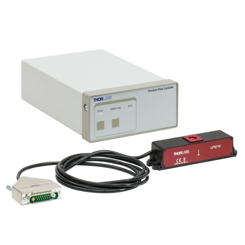 |
| Travel | 20 µm + 5 mm Manual | 25 µm + 1.5 mm Manual | 25 mm | 28 mm | 60.0 mm | 1.1 mm | |
| Maximum Velocity | - | ≤3.6 mm/mina | 180 mm/s | 90 mm/s | - | ||
| Drive Type | Piezo with Manual Actuator | Piezoelectric Inertia Drive | Resonant Piezoelectric Motor | Amplified Piezo | |||
| Possible Axis Configurations | X, XY, XYZ | X, XY, YZ, XZ, XYZ | X | Z | |||
| Mounting Surface Size | 75 mm x 75 mm | 30 mm x 30 mm | 85.0 mm x 50.7 mm | 110.0 mm x 75.7 mm | 15 mm x 15 mm | 21 mm x 21 mm | |
| Additional Details | |||||||
ステッピングモーターステージ
こちらの移動ステージは脱着型あるいは内蔵型のステッピングモータを用いており、また300 mmまでの長い移動量が可能です。これらのステージの多くは多軸移動機能を有していたり(PLSXY)、あるいは多軸ステージを組み立てることが可能であったりします(PLSX、クイック接続型XR25シリーズ、LNRシリーズ、NRTシリーズ、LTSシリーズ)。ステージMLJ150/Mは高荷重にも対応する垂直移動ステージです。
| Stepper Motor Stages | |||||
|---|---|---|---|---|---|
| Product Family | PLSX with and without PLST(/M) Top Plate 1" Stage | PLSXY with and without PLST(/M) Top Plate 1" Stage | LNR Series 25 mm Stage | LNR Series 50 mm Stage | |
| Click Photo to Enlarge | 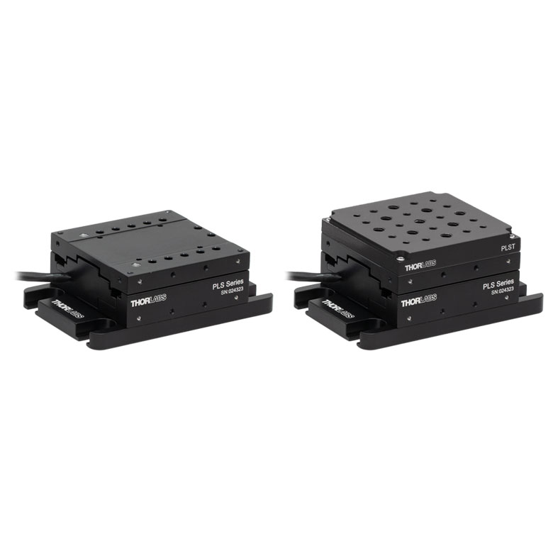 | 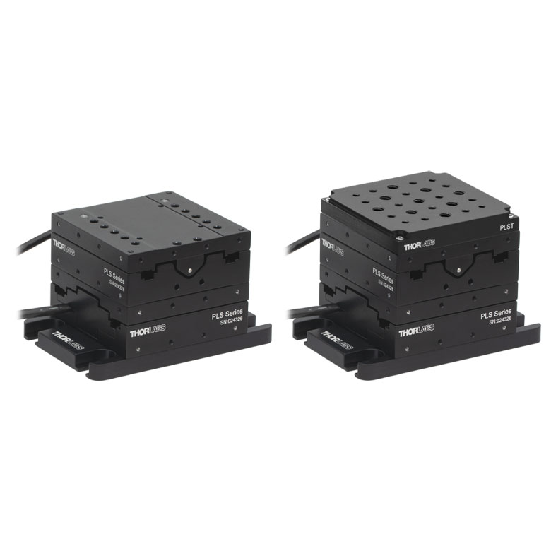 | 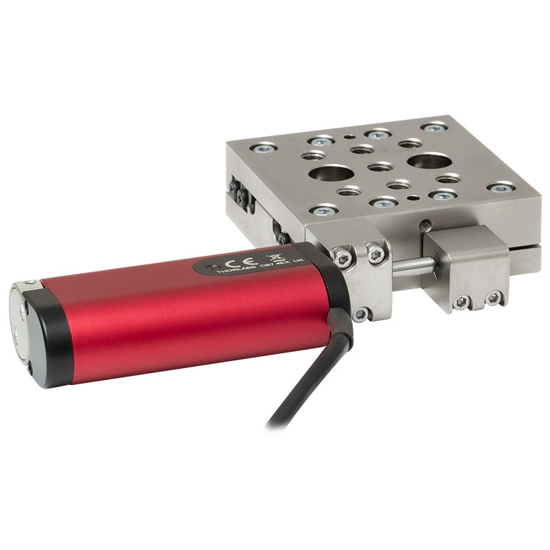 | 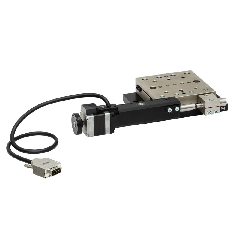 | |
| Travel | 1" | 25 mm | 50 mm | ||
| Maximum Velocity | 7.0 mm/s | 2.0 mm/s | 50 mm/s | ||
| Possible Axis Configurations | X, XY | X, XY, XYZ | X, XY, XYZ | ||
| Mounting Surface Size | 3" x 3" | 60 mm x 60 mm | 100 mm x 100 mm | ||
| Additional Details | |||||
| Stepper Motor Stages | ||||||
|---|---|---|---|---|---|---|
| Product Family | NRT Series 100 mm Stage | NRT Series 150 mm Stage | LTS Series 150 mm Stage | LTS Series 300 mm Stage | MLJ250 50 mm Vertical Stage | |
| Click Photo to Enlarge |  | 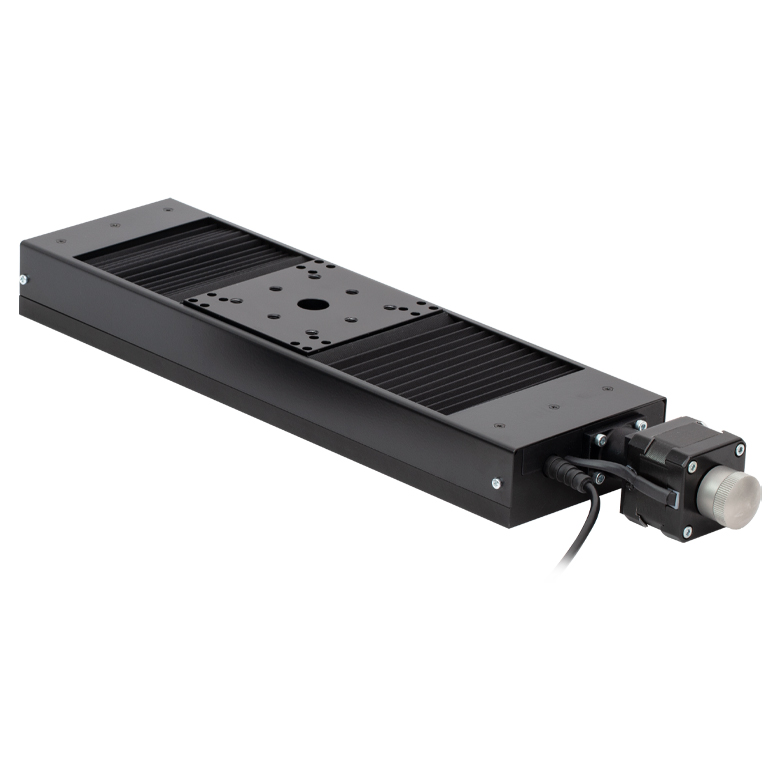 | 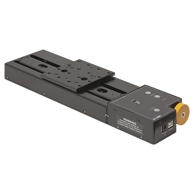 |  | 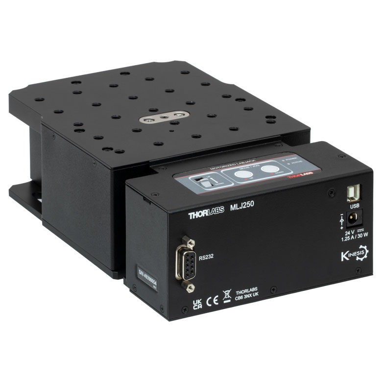 | |
| Travel | 100 mm | 150 mm | 150 mm | 300 mm | 50 mm | |
| Maximum Velocity | 30 mm/s | 50 mm/s | 3.0 mm/s | |||
| Possible Axis Configurations | X, XY, XYZ | X, XY, XYZ | Z | |||
| Mounting Surface Size | 84 mm x 84 mm | 100 mm x 90 mm | 148 mm x 131 mm | |||
| Additional Details | ||||||
DCサーボモーターステージ
脱着型あるいは内蔵型のDCサーボモータを用いた直線移動ステージをご用意しております。これらのステージは薄型で、多軸ステージの構築が可能です。
| DC Servo Motor Stages | ||||
|---|---|---|---|---|
| Product Family | MT Series 12 mm Stages | PT Series 25 mm Stages | MTS Series 25 mm Stage | MTS Series 50 mm Stage |
| Click Photo to Enlarge |  | 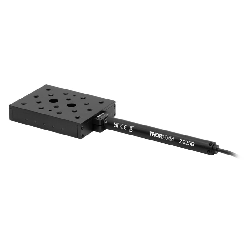 | 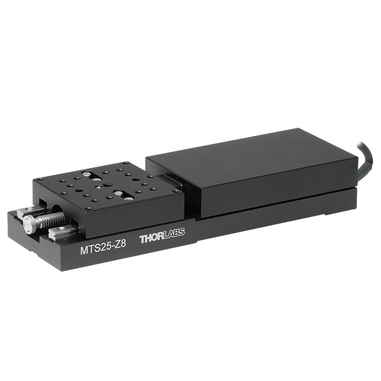 | 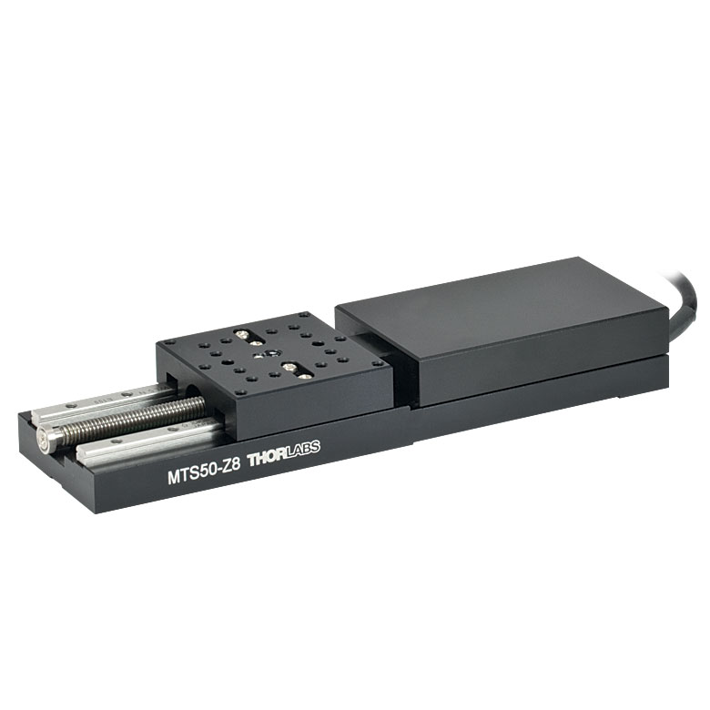 |
| Travel | 12 mm | 25 mm | 25 mm | 50 mm |
| Maximum Velocity | 2.6 mm/s | 2.4 mm/s | ||
| Possible Axis Configurations | X, XY, XYZ | X, XY, XYZ | ||
| Mounting Surface Size | 61 mm x 61 mm | 101.6 mm x 76.2 mm | 43 mm x 43 mm | |
| Additional Details | ||||
| DC Servo Motor Stages | ||||
|---|---|---|---|---|
| Product Family | M30 Series 30 mm Stage | M30 Series 30 mm Monolithic XY Stage | M150 Series 150 mm XY Stage | KVS30 30 mm Vertical Stage |
| Click Photo to Enlarge |  | 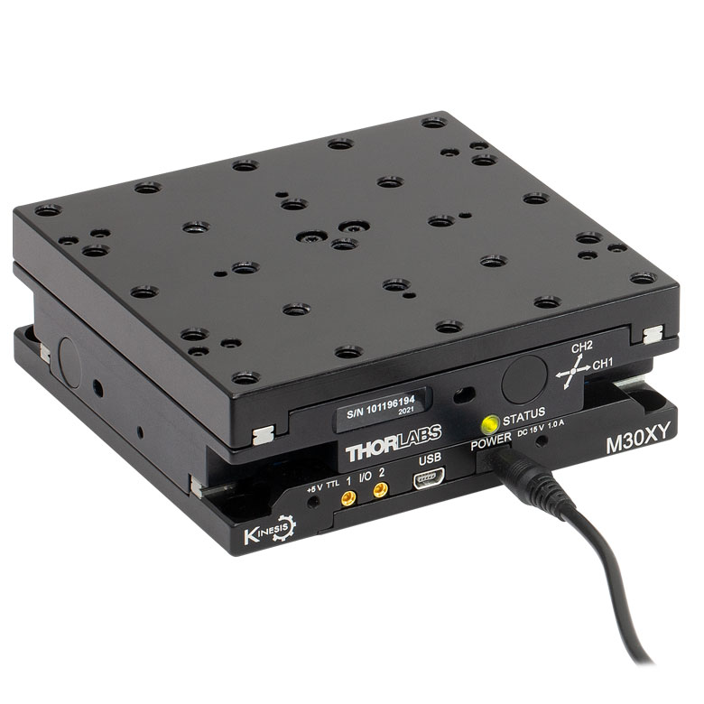 | 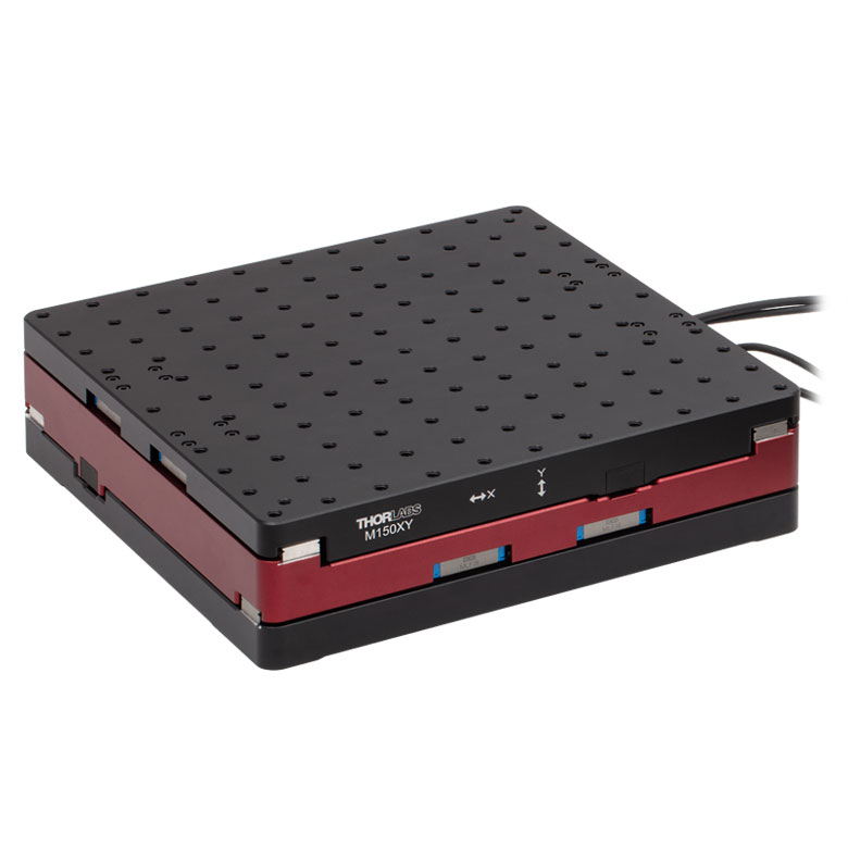 | 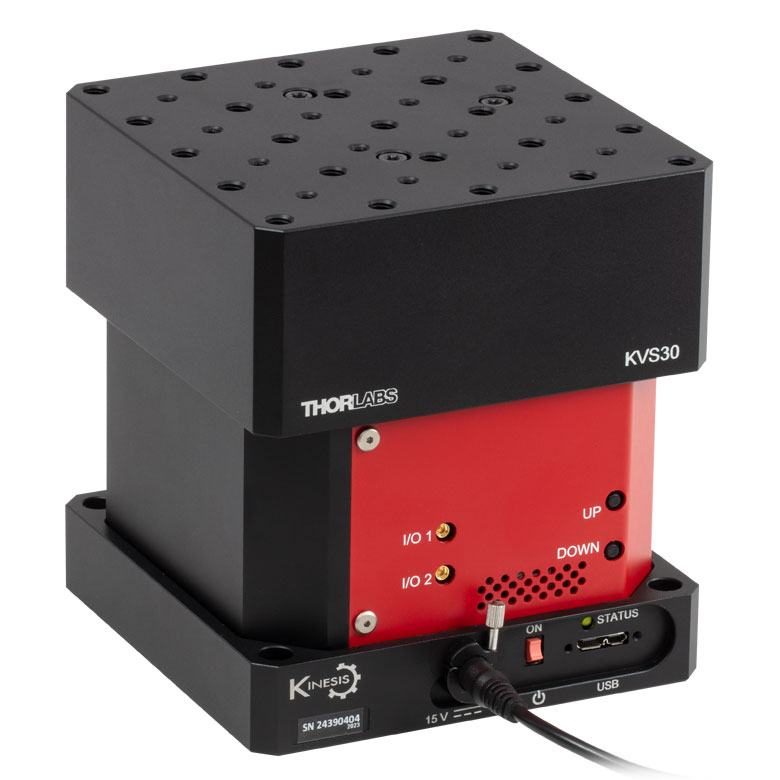 |
| Travel | 30 mm | 150 mm | 30 mm | |
| Maximum Velocity | 2.4 mm/s | X-Axis: 170 mm/s Y-Axis: 230 mm/s | 8.0 mm/s | |
| Possible Axis Configurations | X, Z | XY, XZ | XY | Z |
| Mounting Surface Size | 115 mm x 115 mm | 272.4 mm x 272.4 mm | 116.2 mm x 116.2 mm | |
| Additional Details | ||||
ダイレクトドライブステージ
こちらの薄型ステージにはブラシレスDCサーボモータが内蔵されており、バックラッシュの無い高速移動が可能です。電源が入ってないときは、ステージのプラットフォームにはほとんど慣性が無く、実質的にフリーラン状態になります。そのため電源が入ってないときにステージのプラットフォームが定位置に留まる必要のある用途には適していません。これらのステージを垂直方向に取付けることは推奨しません。
| Direct Drive Stages | |||||
|---|---|---|---|---|---|
| Product Family | DDS Series 50 mm Stage | DDS Series 100 mm Stage | DDS Series 220 mm Stage | DDS Series 300 mm Stage | DDS Series 600 mm Stage |
| Click Photo to Enlarge | 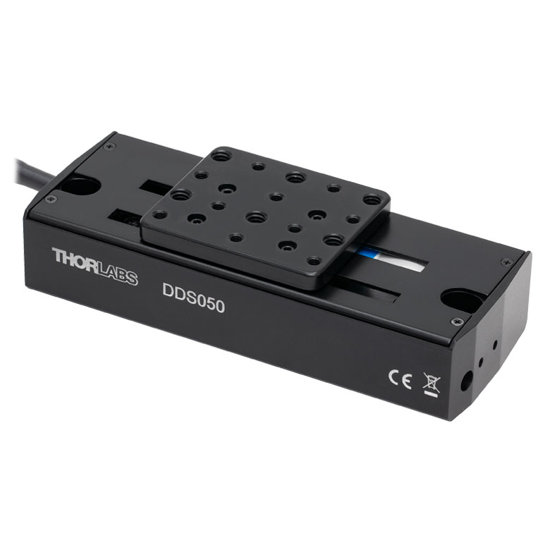 | 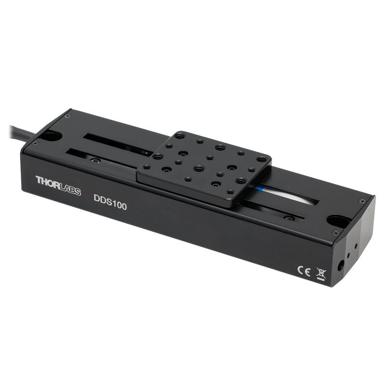 | 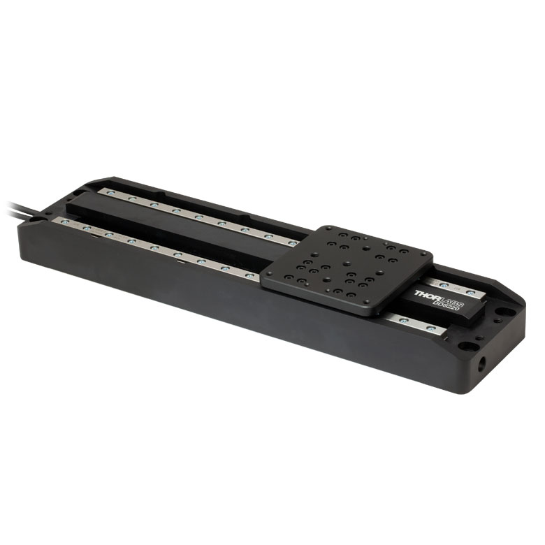 | 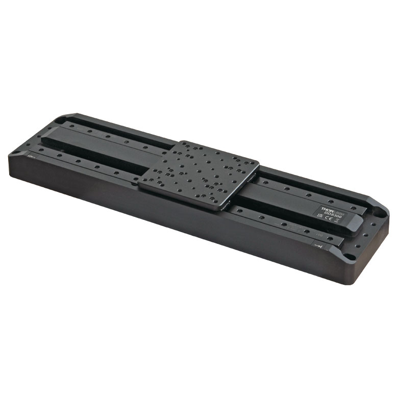 |  |
| Travel | 50 mm | 100 mm | 220 mm | 300 mm | 600 mm |
| Maximum Velocity | 500 mm/s | 300 mm/s | 400 mm/s | 400 mm/s | |
| Possible Axis Configurations | X, XY | X, XY | X | X | |
| Mounting Surface Size | 60 mm x 52 mm | 88 mm x 88 mm | 120 mm x 120 mm | ||
| Additional Details | |||||
ソフトウェア
Kinesisバージョン1.14.56
XAバージョン1.3.0
KinesisおよびXAソフトウェアパッケージには、当社のモーションコントローラを制御するためのGUIが含まれています。
下記もご利用いただけます。
- Firmware Update Utilities
- 通信プロトコル

Figure 789A Kinesis GUI画面
当社では、様々なモーションコントローラを駆動するためのプラットフォームとして、XAソフトウェアパッケージと、今後段階的に終了していくKinesisソフトウェアパッケージの2種類をご用意しています。Kinesisソフトウェアは、当社の全てのモーションコントロール製品に対応しています。XAソフトウェアは開発者向けに改良されたプラットフォームですが、現在のところ定番のモーションコントロール製品の一部に対応している状況です(製品リストはこちらをご覧ください)。このソフトウェアは、継続して重点的に開発が進められており、最終的には当社の全てのモーションコントロール製品に対応する予定です。XAソフトウェアアプリケーションは、2040年までフルサポートを行います。
Kinesis モーションコントロールソフトウェア
Kinesisソフトウェアでは.NETコントロールを使用できるため、最新のC#、Visual Basic、LabVIEW™、あるいはその他の.NET対応言語を使用してカスタムプログラムを作成することができます。また、.NETフレームワークを使用しないアプリケーション用に、ローレベルのDLLライブラリも付属しています。中央シーケンスマネージャ(Central Sequence Manager)は、当社のすべてのモーションコントロール用ハードウェアの統合と同期をサポートしています。
この共通のソフトウェアプラットフォームにより、1種類のソフトウェアツールを習得するだけで、あらゆるKinesisコントローラを簡単に組み合わせて使用することができます。このように1軸システム用から多軸システム用までのあらゆるコントローラを組み合わせ、それら全てを1台のPCの統合されたソフトウェアインターフェイスから制御できます。
Click to Enlarge
Figure 789B ブラシ付きDCサーボモーターコントローラKDC101用のXA GUI
このソフトウェアパッケージには2つの使い方があります。1つはGUI(グラフィカルユーザーインターフェイス)ユーティリティを用いる方法で、この場合はコントローラの到着後すぐに直接的な操作と制御を行なうことができます。もう1つは一連のプログラミングインターフェイスを用いる方法で、ご希望の開発言語によりカスタム仕様の位置決めやアライメント用のプログラムを簡単に作成することができます。
XAモーションコントロールソフトウェア:開発者向けに改良されたプラットフォーム
XAはその基本から理解しやすいように設計されており、スレッドセーフで言語パラダイムに依存しないC、C++、C#/.NETのアプリケーションプログラミングインターフェイスを提供します。また、ネイティブ、.NET言語、PythonまたはLabVIEWアプリケーションに簡単に統合できる言語ラッパーも用意されています。これは前述のKinesisにおけるソフトウェア開発キット(SDK)と同じ機能を果たす一方で、開発者に対してはより効率化されたツールキットを提供します。このソフトウェアは、付属の開発者用ガイドとSDK内のコード例を組み合わせて、複雑でカスタマイズされたアプリケーションとインターフェースを作成しようとするユーザー向けに設計されています。完全なAPIドキュメントはネイティブCライブラリ用に提供されており、.NETラッパーのドキュメントは現在開発中です。.NETラッパーの詳細については当社までお問い合わせください。
XAはKinesisと同等のGUIを備えているだけでなく、デバイスの状態を保存する機能の追加や、異なる種類のデバイス間インテーフェイスにおける一貫性の向上など、利用者のための様々な改善や工夫が実装されています。Kinesisソフトウェアは段階的に終了となりますが、XAは更に改善を進めるとともに、2040年までフルサポートしていく計画です。現行バージョンのXAソフトウェアは、まだ当社のモーションコントローラの一部にのみ対応している状況です。しかし、このソフトウェアは、継続して重点的に開発が進められており、最終的には当社の全てのモーションコントロール製品に対応する予定です。ソフトウェアの適合性に関する情報は、XAのユーザーガイドに記載されています。また、サポートしているデバイスのリストなど、ソフトウェアのその他の詳細情報はこちらをご覧ください。
| Posted Comments: | |
| No Comments Posted |
、移動量450 mm")
 ズーム
ズーム_D1-600.gif)
Click for Details
ステージLTS450C(/M)の寸法とタップ穴の位置を示した図。
ミリ規格の寸法は括弧内に記載されています。
当社の移動ステージLTS450C/Mの移動量は450 mmで、ステッピングモータならびにコントローラが内蔵されています。コントローラは手動のキーパッドでの操作およびPCによるリモート操作が可能です。可動式プラットフォームに25.0 mm間隔で開いている16個のM6タップ穴を利用して、オプトメカニクスを直接取り付けることができます。

 ズーム
ズーム- Mount LTS450C(/M), LTS300C(/M), and LTS450C(/M) Stages in XY Configurations
- Stages can be Mounted in Left- or Right-Handed Setups
- Dowels Included to Ensure Orthogonality
The LTSP1(/M) is a spacer plate, allowing any two LTS translation stages to be mounted in an XY configuration. When assembled, the working height of the upper stage is 3.15" (80 mm). The spatial dimensions of the stage configuration will depend on the orientation (left-handed or right-handed) of the X and Y stages. Please contact Tech Support for the exact dimensions of a particular setup.