 Products Home
ステッピングモーターコントローラーKinesis® K-Cube™
- Peak Power Output up to 12 W
- Seamless Operation with Many of Thorlabs' Stepper Motor Actuators
- Operate Locally via Panel Controls or Remotely from a PC via USB
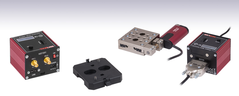
Application Idea
A KST201 Controller Being
Used to Drive an LNR25ZFS Stepper Motor Translation Stage (Sold Separately)
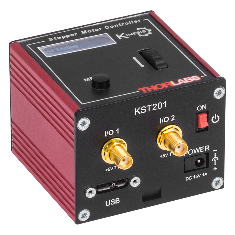
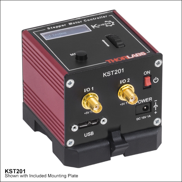
KST201
Power Supply
Sold Separately
Table Mounting Plate
(Included with the KST201)


Please Wait


特長
- コンパクトな設置面積:60 mm x 60 mm x 49.2 mm
- 差動エンコーダーフィードバック(QEP入力)による閉ループ位置決め制御が可能
- 12 W(ピーク)で15 Vまでの2相双極ステッピングモータに対応
- 高分解能な2048マイクロステップ(1フルステップあたり)
- 台形またはS字型の速度プロファイル
- 操作しやすい手動制御
- 速度ホイール:動作の向き(2方向)と速度の制御
- デジタル表示メニュー:位置のプリセットとジョグ動作の設定
- Kinesis®またはAPT™制御用ソフトウェア一式(詳細は「モーションコントロールソフトウェア」のタブをご覧ください)
- ソフトウェアは他のKinesisならびにAPTコントローラにも対応しており、統合システムの開発が可能です
- 設定を保存できるので、上面パネルコントローラよる独立した操作が可能
- 現在のモデルに加えて、旧モデルのT-Cubeコントローラにも対応します
- シングルチャンネルの電源を別途ご用意
- USBコントローラーハブ(別売り)による多軸拡張も可能
- 磁石と固定用クリップの付いた光学テーブル取付け用アダプタが付属
K-CubeステッピングモーターコントローラKST201は、当社の新しい Kinesis®シリーズのコンパクトで高性能なモーションコントローラです。この単チャンネルのコントローラは、当社のZSTおよびZFSアクチュエータなど、低電力(12 Wで最大15 Vまで)のステッピングモータ(「仕様」タブ参照)を容易に手動または自動で制御できるように設計されています。速度プロファイルは台形またはS字型から選択でき、また理論上の高いマイクロステップ分解能(1回転あたり24フルステップモータでは49,152マイクロステップ、200フルステップモータでは409,600マイクロステップ)を有しています。 柔軟性の高いフルコントロール機能を有し、小型ながら高分解能なマイクロステップ駆動が可能です。
ユニットの設置面積は60.0 mm x 60.0 mm x 49.2 mmと非常にコンパクトで、上面パネルのコントローラを使用して手動でモータ位置を調整する際に、システムの近くに配置できるのも便利な点です。テーブル上で操作できると駆動ケーブルの長さを短くでき、ケーブルの管理も容易になります。ユニットの前面には電源スイッチが付いており、このスイッチをオフにするとユーザ設定が保存されます。ユニットの電源を切るときには、必ずこのスイッチをオフにするようにしてください。KST201には長さ1.5 mのA-MicroBタイプのUSB 3.0ケーブルが1本付属します。
USB接続によるプラグアンドプレイが可能で、PC制御による操作が容易です。ソフトウェアプラットフォームとしては、当社の新しいKinesisソフトウェアパッケージと従来のAPT(Advanced Positioning Technology)ソフトウェアパッケージの2種類をご用意しております。Kinesisソフトウェアでは新しい.NETコントロールが使用でき、最新のC#、Visual Basic、LabVIEW™、あるいはその他の.NETに対応する言語を使用してカスタムプログラムを作成するようなサードパーティの開発者も利用することができます。当社の従来のAPTソフトウェアを使用した場合は、ActiveX®プログラミング環境を利用して複雑な動作シーケンスを素早く設定できます。例えば、当社のステージならびにアクチュエータ製品の動作パラメータは、すべてソフトウェアにより自動的に設定されます。これらのソフトウェアパッケージの詳細については、「モーションコントロールソフトウェア」ならびに「APTチュートリアル」タブをご覧ください。
光学テーブル取付け用プレート
ユニットにはコントローラのベース部分をクリップで固定できる取付けプレートが付属します。プレートには2つの磁石が付いており、光学テーブルに一時的に設置する際にご使用いただけます。また、2つのM6キャップスクリュ用ザグリ穴は、恒久的に取り付ける際にご使用ください。光学テーブル取付け用プレートの図面は「仕様」タブでご覧いただけます。
電源の選択
必要な電源(シングルチャンネル、マルチチャンネル、あるいはハブベース)は、その用途とお客様が対応可能な電源をお持ちかどうかに依存します。そのような理由と当社の環境イニシアチブにより、当社では電源をセット販売しておりません。そうすることで、例えばマルチチャンネルやハブをベースとしたシステムが適切な場合に、不要なシングルチャンネルの電源を受け取るようなことは無くなり、コストや煩わしさが省けます。
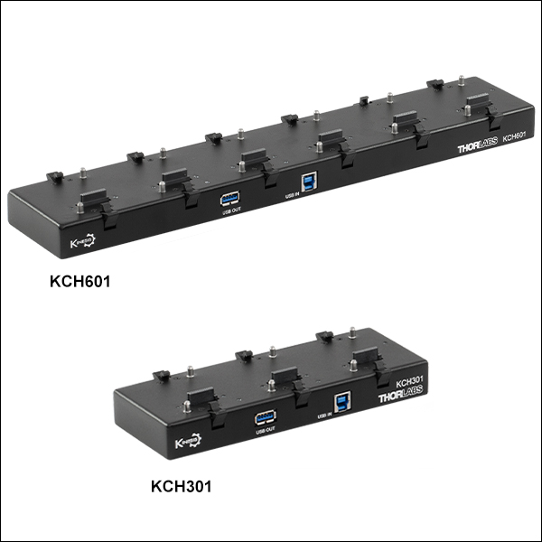
多軸のモーションコントロールの用途では、USBコントローラーハブKCH301またはKCH601(下記参照)をご使用になると、複数のユニットを1台のPCに接続することができます。右下の写真のKCH301は、最大3台のT-CubeまたはK-Cubeコントローラが取り付けられます。右の写真にあるKCH601は、最大6台まで使用可能です。
モーターコントローラKST201に対応する電源は下記のとおりです。
| Other Stepper Motor Controllers | ||
|---|---|---|
| K-Cube™ Single-Channel Controller | 1-, 2-, and 3-Channel Benchtop Controller | Modular 2-Channel Rack System Module |
| KST201 Specifications | |
|---|---|
| Motor Output | |
| Motor Drive Voltage | 12 to 15 V (Depending on Supply) |
| Motor Drive Current | 750 mA (Peak) |
| Motor Drive Type | 12-bit PWM Control |
| Control Algorithm | Open-Loop Microstepping |
| Stepping | 2048 Microsteps per Full Step |
| 49,152 Microsteps per Revolution (24 Step Motora) | |
| Position Feedback | Quadrature Encoder (QEP) Input, 5 V Differential |
| Encoder Feedback Bandwidth | 500 kHz |
| Position Counter | 32 bit |
| Operating Modes | Position and Velocity |
| Velocity Profile | Trapezoidal or 'S' Profile |
| Motor Drive Connector (15 Way D-Type) | |
| Motor Drive Outputs | Phase A and B |
| Quadrature Encoder (QEP) Input | Differential |
| Limit Switch Inputs | Forward, Reverse (+ Common Return) |
| Encoder Supply | 5 V |
| Front Panel Controls | |
| Sprung Potentiometer Wheel | Variable-Speed Bidirectional Velocity Control, Forward/Reverse Jogging or Position Presets |
| Input Power Requirements | |
| Voltage | 12 to 15 V Regulated DC (15 V Recommended) |
| Current | 1 A (Peak) |
| General | |
| USB Connector Type | USB 3.0 |
| USB Connection Speed | USB 1.1 Full Speed (12 Mbps) |
| Housing Dimensionsb (W x D x H) | 60.0 mm x 60.0 mm x 49.2 mm (2.36" x 2.36" x 1.94") |
| Compatible Motor Specifications | ||
|---|---|---|
| Motor Type | 2-Phase Bi-Polar Stepper | |
| Peak Power | 12 W | |
| Rated Phase Current | Up to 1 A Peak | |
| Step Angle Range | 1.8° to 20° | |
| Motor Drive Mode | Current | |
| Coil Resistance (Nominal) | 5 to 20 Ω | |
| Coil Inductance (Nominal) | 2 to 5.5 mH | |
| Position Control | Open Loop | |
| Compatible Thorlabs Stages and Actuators | |
|---|---|
| Linear Translation Stage | LNR25ZFS |
| Linear Actuators | ZST206, ZST213, ZST213B, ZFS06, ZFS13, ZFS13B, ZFS25B, ZST225B |
Click to Enlarge
KST201と付属の光学テーブル用アダプタの図面
モータ制御コネクタ
Dタイプ メス型
| Pin | Description | Pin | Description | Pin | Description |
|---|---|---|---|---|---|
| 1 | Ground | 6 | Phase A -ve | 11 | Enc A +ve |
| 2 | CCW Limit Switch | 7 | Phase A +ve | 12 | Enc A -ve |
| 3 | CW Limit Switch | 8 | For Future Use | 13 | Enc B +ve |
| 4 | Phase B -ve | 9 | Stage Identification | 14 | Enc B -ve |
| 5 | Phase B +ve | 10 | +5 V DC | 15 | For Future Use |
TRIG 1SMAメス型 | TRIG 2SMAメス型 |
 | |
| +5 V TTL | +5 V TTL |
| これらのコネクタからは5 Vのロジックレベルの信号を入出力します。トリガ信号を外部機器に出力する、あるいは外部機器から入力するかについては設定することができます。それぞれのポートでロジックレベルの調整や、トリガの入力あるいは出力の設定が可能です。 | |
PC接続用コネクタ*
*このUSBポートはUSB3.0対応ですが、USB2.0でもご使用いただけます。USB 2.0 を使用する際は、Micro-Bタイプコネクタを上図の網掛け部分に接続します。KST201にはAタイプ - Micro-BタイプのUSB 3.0ケーブルが1本付属します。
K-Cube取付けオプション
K-Cubeコントローラの光学テーブルへの固定方法を2種類ご用意しております。1つは光学テーブル取付けプレートで、すべてのK-Cubeに付属しており、1台のコントローラを光学テーブルに取り付けることができます。もう1つは、3ポートあるいは6ポートのUSBコントローラーハブ(別売り)で、当社のK-Cubeコントローラを取り付け、それらに電力を供給することができます。詳細は下記をご覧ください。
光学テーブル取付けプレート
各ユニットには、コントローラのベース部分をクリップで固定できる取付けプレートが付属します(下の動画参照)。プレートには2つの磁石が付いており、光学テーブルに一時的に設置する際にご使用いただけます。また、2つのM6キャップスクリュ用ザグリ穴は、恒久的に取り付ける際にご使用ください。光学テーブル取付けプレートの図面は「仕様」タブでご覧いただけます。
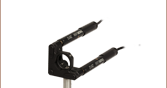
Kinesis USBコントローラーハブ
USBコントローラーハブKCH301やKCH601を用いると、複数のユニットを取り付けて、それらを1台のPCに接続することができます。 コントローラーハブは、3台(KCH301)もしくは6台(KCH601)のK-CubeやT-Cubeをサポートするハブ部分と、壁コンセントに接続して電力を供給する電源部分から構成されています。K-Cubeはユニットについているクリップで簡単にハブに取り付けられますが、T-Cube(現製品および旧製品)の取り付けには、下の動画のようにアダプタープレートKAP101が必要です。 複数のコントローラをお使いになるときには、ハブをご使用になるとUSB用と電源用のケーブル本数を大幅に削減することができます。
K-Cube用光学テーブル取付けプレート
T-Cubeと違い、すべてのK-Cubeには、コントローラのベース部分をクリップで固定できる取付けプレートが付属します。プレートには2つの磁石が付いており、光学テーブルに一時的に設置する際にご使用いただけます。また、2つのM6キャップスクリュ用ザグリ穴は、恒久的に取り付ける際にご使用ください。
Kinesis USBコントローラーハブ
3ポートまたは6ポートのUSBコントローラーハブを用いると、多軸の操作をする際に複数のコントローラを1台のPCに接続することができます。K-Cubeはハブに直接取り付けられますが、T-Cubeの取り付けにはアダプタープレートKAP101が必要です。
| K-Cube vs. T-Cube Feature Comparison | ||
|---|---|---|
| Feature | KST201 K-Cube | TST101 T-Cube |
| Kinesis Software Compatibility | ||
| APT Software Compatibility | ||
| Kinesis USB Controller Hubs Compatibility | Requires KAP101 Adapter | |
| TCH002 T-Cube USB Controller Hubs Compatibility | N/A | |
| Power Switch | N/A | |
| Bidirectional SMA Trigger Port | 2 | N/A |
| Computer Connectiona | USB 3.0 Micro B (USB 2.0 Compliant) | USB 2.0 Micro B (USB 2.0 Compliant) |
| Included Mounting Plate | ||
| Size (L x W x H) | 60.0 mm x 60.0 mm x 49.2 mm (2.36" x 2.36" x 1.94") | 60.0 mm x 60.0 mm x 49.2 mm (2.36" x 2.36" x 1.94") |
| On-Unit Digital Display Menu | N/A | |
| Go To Position | Only via Software | |
| Homing Options | Only via Software | |
| Velocity Control | Only via Software | |
| Joystick Mode | Only via Software | |
| Jog Step Size | Only via Software | |
| Teach Position | Only via Software | |
| Screen Brightness | N/A | |
| Disable Movement | N/A | |
| Stage Select | Only via Software | |
Kinesis®モーションコントローラのご紹介
旧世代のT-Cube製品から大幅に改良されたK-Cubeのラインナップでは、新しいKinesis ソフトウェアの導入だけでなく、物理的設計やファームウェアの全面的な見直しも行い、汎用性を高めています。
T-Cubeとは異なり、すべてのK-Cubeコントローラにはデジタルディスプレイが付いています。このディスプレイは基本的な入出力情報の表示を行うだけでなく、指定位置への移動コマンドや、ホーミング、速度制御、ジョグ動作などを含む様々なメニューオプションの選択機能も備えています。ユニットの速度ホイールとメニューボタンを使用して、利用可能な機能をスクロールしてご覧いただくことができます。各ユニットには電源スイッチがあり、これをオフにするとお客様が調整した設定はすべて保存されます。また、5 V TTLロジック信号を入出力する双方向性SMAトリガーポートが2つ付いています。
右の表では、K-Cube KST201と旧世代のT-Cube TST101の2種類のモーションコントローラの機能を比較しています。
Click to Enlarge
ステッピングモーターコントローラ
K-Cube Kinesis KST201
Kinesis USBコントローラーハブ
Kinesis USB 2.0コントローラーハブは、K-Cubeコントローラの機能を補完する製品です。USBハブには3台用と6台用の2種類があり、複数のK-CubeやT-CubeのコントローラがホストPCと通信できるように設計されております。これらのハブはT-Cube製品との後方互換性があります。
K-Cubeはユニットについているクリップで簡単にハブに取り付けられますが、T-Cube(現製品および旧製品)の取り付けには、右下の動画のようにアダプタープレートKAP101が必要です。 複数のコントローラをお使いになるときには、ハブをご使用になるとUSB用と電源用のケーブル本数を大幅に削減することができます。
K-Cube用光学テーブル取付けプレート
Kinesis USBコントローラーハブ
3ポートまたは6ポートのUSBコントローラーハブを用いると、多軸の操作をする際に複数のコントローラを1台のPCに接続することができます。K-Cubeはハブに直接取り付けられますが、T-Cubeの取り付けにはアダプタープレートKAP101が必要です。
当社では幅広い種類のモーションコントローラを駆動できるよう、Kinesis® ソフトウェアパッケージと従来のAPT™(Advanced Positioning Technology)ソフトウェアパッケージの2種類のプラットフォームをご用意しております。どちらのパッケージも小型で低出力のシングルチャンネルドライバ(K-Cube™やT-Cube™など)から高出力でマルチチャンネルのモジュール式19インチラックナノポジショニングシステム(APTラックシステム)まで幅広い種類のモーションコントローラをカバーするKinesisシリーズのデバイスを制御できます。
Kinesisソフトウェアには、最新のC#、Visual Basic、LabVIEW™またはその他の.NETに対応する言語を使用してカスタムプログラムを作成するサードパーティの開発者向けに、.NETコントロールが付属しています。また、.NETフレームワークを使用しない用途向けに低級言語用のDLLライブラリも付いています。センターシーケンスマネージャが、当社の全てのモーションコントロールハードウェアの統合と同期をサポートします。

KinesisのGUIスクリーン
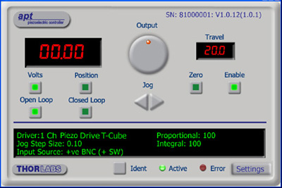
APTのGUIスクリーン
当社従来のAPTシステムソフトウェアプラットフォームは、C#、Visual Basic、LabVIEWまたはその他のActive-Xに対応する言語を使用してカスタムプログラムを作成するサードパーティの開発者向けに、ActiveXをベースとしたコントロールが付属しています。また、ハードウェア無しでカスタムプログラムの開発を行うためのシミュレーターモードも付いています。
これらの共通のソフトウェアプラットフォームにより、あらゆるKinesisとAPTコントローラをシングルアプリケーションに簡単に組み込むことができます。ソフトウェアツールは1セット習得するだけで共通した操作が可能です。シングルチャンネルシステムからマルチチャンネルシステムまで、あらゆるコントローラを組み合わせ、全てを1台のPCのソフトウェアインターフェイスから制御することが実現可能です。
このソフトウェアパッケージを使用するには2つの手段があります。GUI(グラフィカルユーザーインターフェイス)ユーティリティを使用したコントローラとの直接対話ならびに「out of the box」コントロール、またはご選択の開発言語でカスタム統合の位置決めやアライメントソリューションを簡単にプログラムできる一連のプログラミングインターフェイスです。
APTシステムソフトウェアをよりご理解いただけるために様々なチュートリアルビデオもご用意しております。ビデオではソフトウェアの概要とAPT Configユーティリティをご説明しています。また、ソフトウェアのシミュレーターモードを利用すると、コントローラを接続しないでソフトウェアを試すことができます。その方法を説明したビデオもあります。これらのビデオは「APTチュートリアル」タブ内のリンクからご覧いただけます。
ソフトウェア
Kinesis バージョン 1.14.47
このKinesisソフトウェアパッケージには、当社のKinesisならびにAPT™システムコントローラを制御するためのGUIが含まれています。
下記もご用意しております:
- 通信プロトコル
ソフトウェア
APT バージョン 3.21.6
このAPTソフトウェアパッケージには、当社のAPT™およびKinesisシステムコントローラを制御するためのGUIが含まれています。
下記もご用意しております:
- 通信プロトコル
Kinesis®ソフトウェアでは新しい.NETコントロールが使用でき、最新の最新のC#, Visual Basic, LabVIEW™、ほかの.NET対応言語を使用する開発者がカスタムにプログラムを作成することもできます。
C#
このプログラミング言語はマルチプログラミングパラダイムやマルチプログラミング言語が使用可能となるよう設計されているため、複雑な問題が簡単かつ効率的に解決できます。型付け、命令型、宣言型、関数型、ジェネリック、オブジェクト指向、そしてコンポーネント指向が含まれます。 この共通のソフトウェアプラットフォームにより、1セットのソフトウェアツールを習得するだけで、あらゆるKinesisコントローラを簡単に組み合わせることができます。このようにして1軸システムのコントローラから多軸システムのコントローラまで、様々なコントローラを組み合わせ、全てを1台のPCのソフトウェアインターフェイスから制御することが可能となりました。
Kinesisシステムソフトウェアを使用するには2つの手段があります。コントローラを直接つないで制御を行なう付属のGUI(グラフィカルユーザーインターフェイス)ユーティリティ、またはご希望の開発言語でカスタム仕様の位置決めやアライメントを簡単にプログラムできる一連のプログラミングインターフェイスです。
Kinesisモーションコントロールライブラリの構築の参考となる実行可能なプロジェクト機能拡張例については下のリンクをクリックしてください。なお、Quick Startのプロジェクト例の実行には別の統合開発環境(IDE)(Microsoft Visual Studioなど)が必要です。C#のプロジェクト例はKinesisソフトウェアパッケージに付属する.NETコントロールで実行可能です(詳細は「Kinesisソフトウェア」タブをご覧ください)。
 | Click Here for the Kinesis with C# Quick Start Guide Click Here for C# Example Projects Click Here for Quick Start Device Control Examples | |
LabVIEW
LabVIEWは、.Netコントロールを介してKinesisまたはAPTベースのコントローラとの通信に使用できます。LabVIEWでは、ツールとオブジェクトでフロントパネルとして知られるユーザーインターフェイスを構築した後、グラフィカル表記の関数を使ってコードを追加し、フロントパネルのオブジェクトを制御します。下記のLabVIEWチュートリアルでは.Netコントロールを使用してLabVIEW内KinesisまたはAPT駆動デバイス用の制御GUIを作成するための情報をご提供しています。 LabVIEWでコントローラを制御する基本的な方法や、LabVIEW GUIを用いてデバイスを操作する前に行うべき設定の手順についても解説しています。
 | Click Here to View the LabVIEW Guide Click Here to View the Kinesis with LabVIEW Overview Page | |
こちらのページでご覧いただくAPTビデオチュートリアルは、付属のATPユーティリティに関する説明と、いくつかのプログラミング環境におけるAPTシステムのプログラミングに関する説明の2つの部分から構成されています。
免責事項:これらの動画は、当初はAdobe Flashによって作成されました。2020年のAdobe Flashのサポート終了後、これらのチュートリアルは再録画されています。各動画の下にはFlash Playerの操作ボタンが見えますが、機能はしません。
APTコントローラには、APTUserユーティリティとAPTConfigユーティリティが付いています。APTUserを用いると、直感的操作が可能なグラフィック制御パネルを介して、APTで制御するハードウェアに素早く簡単に接続することができます。APTConfigは「オフライン」ユーティリティで、メカニカルステージのタイプを事前に選択し、それらを特定のモーションコントローラに対応付けるなど、システム全体のさまざまな設定を行うことができます。
APT Userユーティリティ
下の左側の動画では、APTUserユーティリティの操作概要について説明しています。シングルチャンネルコントローラのOptoDriverは、制御用のPCが無くても前面パネルのコントローラを介して操作できます。前面パネルのコントローラに保存されている操作に関する設定は、APTUserユーティリティを使用して変更することができます。そのプロセスは下の右側の動画でご覧いただけます。
APT Configユーティリティ
シミュレートされたハードウェア構成のセットアップや、メカニカルステージの特定のモータードライブチャンネルへの対応付けなど、APT Configユーティリティを使用してAPTシステム全体の様々な設定ができます。下の最初の動画ではAPT Configの概要をご覧いただけます。シミュレートされたハードウェア構成の作成方法やステージと対応付ける方法についての詳細は、その右側の2つの動画でご覧いただけます。
APTのプログラミング
APTソフトウェアシステムは、ActiveXコントロールのコレクションとして実装されています。ActiveXコントロールは言語に依存しないソフトウェアモジュールで、グラフィカルユーザーインターフェイスとプログラミングインターフェイスの両方を提供します。ハードウェアユニットのタイプごとにActiveXコントロールのタイプがあります。例えば、Motor ActiveXコントロールはすべてのタイプのAPTモーターコントローラ(DCまたはステッパ)の操作に対応します。ActiveXコントロールは多くのWindowsソフトウェア開発環境やソフトウェア言語で直接サポートされており、そのようなコントロールがカスタムアプリケーションに組み込まれると、そこに含まれるすべての機能が即座にアプリケーションで利用できるようになります。下の動画では、LabVIEW、Visual Basic、Visual C++によるAPT ActiveXコントロールの基本的な使用方法について説明しています。これ以外に、LabWindows CVI、C++ Builder、VB.NET、C#.NET、Office VBA、Matlab、HPVEEなどの多数の言語でもActiveXはサポートされています。これらの言語環境についてはチュートリアルのビデオでは特に取り上げていませんが、動画内の考え方の多くは他の言語環境でも適切に使用できます。
Visual Basic
Part 1ではVisual Basicで動作するAPT ActiveXコントロールを設定する方法について説明しており、Part 2では独自の位置決めシーケンスをプログラミングする方法について説明しています。
LabVIEW
LabVIEWはActiveXをフルサポートしています。下の一連のチュートリアルビデオでは、APTによる独自のモーションコントロールシーケンスを作製する際の基本的な構成要素を示しています。まずソフトウェア開発中にオンラインヘルプを呼び出す方法をご紹介します。Part 2ではAPT ActiveXコントロールの作成方法をご紹介します。ActiveXコントロールではメソッド(機能)とプロパティ(数値設定)の両方を設定できます。Part 3と4では、ActiveXコントロールで示されたメソッドとプロパティを作成してワイヤで接続する方法をご紹介します。最後に、Part 5では全体をまとめて、独自の移動シーケンスを実行するLabVIEWのプログラム例をご紹介します。
Part 1:オンラインヘルプへのアクセス方法
Part 2:ActiveXコントロールの作成方法
Part 3:ActiveXのメソッドの作成方法
Part 4:ActiveXのプロパティの作成方法
Part 5:ActiveXコントロールの開始方法
下のチュートリアルビデオでは、メソッドおよびプロパティのノードを作成する別の方法について説明しています。
ActiveXメソッドの作成方法(別の方法)
ActiveXプロパティの作成方法(別の方法)
Visual C++
Part 1ではVisualC++で動作するAPT ActiveXコントロールを設定する方法について説明しており、Part 2では独自の位置決めシーケンスをプログラミングする方法について説明しています。
MATLAB
当社のAPTポジショナにMATLABおよびActiveXコントロールを使用する場合は、こちらの資料をご覧ください。
プログラマー向けとして、LabVIEWでAPTソフトウェアをプログラミングする方法もこちらからご覧いただけます。
| Posted Comments: | |
Joe Foley
(posted 2023-08-24 13:14:14.057) Hello
I have been reviewing the Kenesis software download in hopes of creating a LabVIEW .NET base VI. It seems to be missing the "Thorlabs.MotionControl.Controls.dll".
Any help would be greatly apricated. Please disregard the need for an offline installer.
Regards,
Joe Foley fguzman
(posted 2023-08-25 07:04:49.0) Thanks for your enquiry. There are two solutions to this problem that we've tested and proven to work:
1 - Force LabVIEW to load the Common DLL prior to creating the K-Cube. You can do this by calling the static function 'GetSIUnitSymbol' which is contained in the Common DLL. This creates an additional project dependency in the LabVIEW project for the Common DLL which means that LabVIEW DOES check the VI and LabVIEW project location and it doesn't crash.
2 - Provide the Common DLL in the LabVIEW program folder. Simply copy the files that are missing (in this case "Thorlabs.MotionControl.Tools.Common.dll") to the folder named "C:\Program Files (x86)\National Instruments\LabVIEW". Copy all of the Kinesis files just to be on the safe side. Joe Foley
(posted 2023-08-23 15:16:43.3) Hello,
I need to do an offline installation of the Kinesis Version 1.14.37 software. I get an error when I attempt to copy it to a removable USB drive. Is there an offline installer available?
Regards,
Joe Foley fguzman
(posted 2023-08-25 07:11:03.0) Thanks for your enquiry. I have addressed your other enquiry. If you need further assistance please contact your local Thorlabs office techsupport@thorlabs.com Martin Tmej
(posted 2022-06-22 10:30:39.837) Hello, is it possible to connect a signal from external scale to control the position, please?
Thank you, Martin Tmej cwright
(posted 2022-06-22 09:31:08.0) Response from Charles at Thorlabs: Thank you for your query. Unfortunately the position of a stage connected to the KST101 cannot be scaled according to an analogue input like it can be through the KPZ101 for example. There are trigger inputs on this controller though, so it would be possible to move the device between specific positions when a TTL input signal is received. Qiuchen Zhao
(posted 2021-10-14 11:10:10.803) Hi,
I am a KST 101 user in Purdue University. I met a question when i was trying to control a ZSF13B with Matlab. Is it possible to drive KST101 with matlab? I could get the moter series number with motor.listdevices, but always shows "Stage not recognised" when I try to connect the device.
Thank you,
Qiuchen cwright
(posted 2021-10-15 10:38:46.0) Response from Charles at Thorlabs: Thank you for your query. While our stages can sometimes be used in Matlab with the dlls they may not always work due to compatibility issues that arise with different Matlab and Kinesis versions. This is why we do not officially support Matlab. The best approach when using Matlab is to send serial commands from our APT communication protocol: https://www.thorlabs.com/Software/Motion%20Control/APT_Communications_Protocol.pdf Håkan Olsson
(posted 2021-05-17 04:53:03.85) Hello is it possible to controll the kst101 in simple way with an analog input signal ie 0-5v trigger1 forward motion and trigger2 0-5v backwards motion preferable steppless speed relative to 0-5v
Rgds Håkan cwright
(posted 2021-05-17 06:18:17.0) Response from Charles at Thorlabs: Hello Håken and thank you for your query. No this is not possible with the KST101. The trigger ports use TTL signals and a high or low signal can be used to initiate a move but the voltage cannot control the velocity. Paul Farnsworth
(posted 2020-08-15 19:01:42.007) I am attempting to control some of your stepper motor actuators through the Kinesis software using Labview. I need to trigger moves externally, and the descriptions of the trigger functions imply that they could be used for this purpose. However, I can find nothing in the literature that explains how the trigger event is connected to the desired move. Suppose I set the trigger mode for one of the two triggers to TrigIN_Absolute_Move. What then? Does a subsequent move command wait for a trigger before it executes? I would appreciate any suggestions. cwright
(posted 2020-08-18 05:43:41.0) Response from Charles at Thorlabs: Thank you for your query. The triggers use 5V TTL logic levels and when using the triggers as an input for a move absolute, the move will be initialised when it sees a transition from the inactive to active logic state (rising or falling edge). This is referred to as the trigger polarity. If the trigger polarity is 'Trigger High' the inactive state is 0V and the move will trigger on a rising edge to 5V and vice versa for 'Trigger Low'. To trigger multiple moves the logic level will have to return to the inactive state before triggering the next move. user
(posted 2020-01-19 08:04:23.547) What's the best way to communicate to kst101 controllers via python? Do you have example code? AManickavasagam
(posted 2020-01-23 06:50:59.0) Response from Arunthathi at Thorlabs: We do not offer a documentation for the use of the KST101 with Python yet. However, we have some examples for other controllers that are based on the C API and .NET API that are included in the Kinesis software package. I have contacted you directly with the available examples which you could use as reference to build your code. Ayuob Al
(posted 2019-11-20 15:24:22.68) I bought KST101 controller to control the motion of stepper motor. The stepper motors that I have are : stepper motor 23hs22-2804s and Parker AMP 5023-067 Servo Motor. I did all of the hardware wiring, but the neither one of the motor moves correctly. They either don't work, or they keep spinning in the wrong direction. I’m not sure if those two motors are compatible with this controller. Hope someone would give me some help since I already bought the controller. cwright
(posted 2019-12-03 11:03:50.0) Response from Charles at Thorlabs: Hello Ayuob, I’m sorry to hear you are having these issues but unfortunately we cannot support the use of third party equipment with our controllers and advise against this due to the possibility of causing damage to either the controller or the motor. I would suggest though that the servo will not work with a stepper motor controller without extensive modifications to the controller. user
(posted 2019-07-30 13:16:11.127) Can it be controlled and programmed without ActiveX control ?
If I can by serial communication or VISA command, I want to use these rather than activeX. AManickavasagam
(posted 2019-07-30 05:06:43.0) Response from Arunthathi at Thorlabs: Thanks for your query. Yes you are able to control the KST101 and all our APT and Kinesis compatible devices with serial communication. Please see the link to the document describing the communications command: https://www.thorlabs.com/Software/Motion%20Control/APT_Communications_Protocol.pdf. jean-paul.adam
(posted 2019-01-11 07:04:46.557) Hi, I am using KST101 controllers on a PC with windows8.1 with APT. They work fine but I would like to interface them using python. Can you offer me some support for this? Best regards bhallewell
(posted 2019-01-14 03:42:16.0) Response from Ben at Thorlabs: Thank you for your question. We have an area on our website which covers some of the documentation & examples which we hold for third party programming here.
https://www.thorlabs.com/navigation.cfm?guide_id=2251
This support includes programming with LabVIEW, APT & C#/VB. This covers support for our legacy motion control software APT, as well as Kinesis which replaces APT adding improved functionality.
For Python, whilst we currently don't hold documentation or examples on the website, we may still be able to assist you. I will contact you directly to see if I can help. douglas.shepherd
(posted 2018-07-13 19:09:37.957) We are attempting to program three KST101 units using Kinesis in C#. Do you have an example on connecting, initializing, setting up, homing, and setting up triggering for this unit? Thank you. bhallewell
(posted 2018-07-17 09:44:15.0) Response from Ben at Thorlabs: Thank you for your email here. I would recommend taking a look at the .NET API included with the Kinesis software package. This will provide a KST101 C# example.
Please also see our Kinesis C# Example & Quick Start projects on the following page.
https://www.thorlabs.com/newgrouppage9.cfm?objectgroup_id=10285
These include a range of WinForms & Console Applications. A similar example from this list would be the 'KDC_Console_net_managed' example which shares many Generic KCube Motor commands & device manager commands with the KST101 device. The KDC101 is a Servo Motor controller, whereas KST101 is a Stepper Motor controller.
For querying & configuring Trigger Settings I would advise looking at Thorlabs::MotionControl::GenericMotorCLI::ControlParameters::KCubeTriggerConfigParams Struct Reference within the .NET API. mkarakose
(posted 2018-04-27 14:58:20.29) Hi,
We are using ZFS06 with KST101 successfully. We use ZFS06 with a mirror holder and the mirror should touch another surface but ZFS06 pushes so hard that the mirror cracks. We want the mirror surface to touch the other one but not crack and the movement of ZFS06 to stop. We were wondering if it is possible to reduce the drive voltage supplied by KST101 to ZFS06, so that the pushing strength of ZFS06 will be lowered. Thanks in advance.
Hoping to hear from you soon!
Best Regards
Mustafa Karaköse AManickavasagam
(posted 2018-04-30 11:58:31.0) Response from Arunthathi at Thorlabs: Thanks for your query. I have contacted you directly with a list of possibilities that you might want to consider for your application. n0a.rolv
(posted 2018-04-11 09:24:38.83) The Kinesis user guide says that each unit is shipped with a calibration file, which mine didn't. Where can I get it? bhallewell
(posted 2018-04-16 11:22:55.0) Response from Ben at Thorlabs: Thank you for your feedback. As per our Kinesis manual, calibration files are only provided with our NRT100, NRT150, LTS150, LTS300 and MLJ050 series stages as well as DRV013 and DRV014 actuators. I will feed this back onto our Marketing team with a view to make this more clear in the APT manual. nkaddy
(posted 2017-07-27 10:08:59.89) How would I control the KST101 using a joystick? Can this be done directly without running through a PC? bhallewell
(posted 2017-07-27 10:37:59.0) Response from Ben at Thorlabs: Within Kinesis, the menu item 'Input Devices' on the main application File menu can be used to open and configure a Joystick or Game Controller. Further details of setting up a Joystick for this function can be found in the Kinesis help file from the Kinesis software download, which can be found here.
https://www.thorlabs.com/software_pages/ViewSoftwarePage.cfm?Code=Motion_Control julien.gautier
(posted 2016-10-26 14:20:49.083) Hi
I try to install apt software on XP 32 bits
The software seem to be well installed but when i click on it I have the following message :(nul) is not a Win 32 application
Could you help me
Best regards bhallewell
(posted 2016-10-27 03:26:41.0) Response from Ben at Thorlabs: Unfortunately our up-to-date software packages no longer support Windows XP. I will contact you directly to discuss a solution. william.dai
(posted 2016-06-14 17:49:03.78) Is this controller compatible with the NRT100, 100 mm Motorized Linear Translation Stage? I am designing a fixture that benefits from the smaller footprint of this controller. If necessary, I can purchase the BSC201 controller, but the size and cost is not preferred. bwood
(posted 2016-06-15 05:05:28.0) Response from Ben at Thorlabs: Thank you for your feedback. Unfortunately, the NRT series of stages require the higher specifications of the BSC benchtop stepper motor controllers for correct performance. Thus we cannot recommend using the KST101 to control the NRT100. dbarnard
(posted 2016-02-18 16:08:37.083) Which version of the .NET framework are the Kinesis DLLs built with? I add them as references to my .NET 4.6.1 x64 project, but at run-time, it says that the
Thorlabs.MotionControl.DeviceManagerCLI.dll or one of its dependencies could not be loaded.
Usually, that means a x86 vs. x64 mismatch or an incompatible CLR version mismatch. I don't see it documented anywhere which version of .NET is needed for these DLLs.
I am using a TST101.
Also, is there a sample project that I could compile like the ones I see in the .chm file? Thanks. bwood
(posted 2016-02-19 06:11:11.0) Response from Ben at Thorlabs: Thank you for your feedback. Kinesis is built using .Net 4.5. The error you are seeing is usually due to either:
·Incompatible .Net versions.
4.6.1 is backward compatible to 4.5 so this should not be a problem here.
·Incompatible Platform.
The Kinesis DLLs are platform specific, so you should build your application using either x86 or x64. AnyCPU may work but may result in undefined issues
·Missing support DLLs
The Kinesis .Net DLLs depend upon a number of Native C DLLs. It is important that these are copied to your project output folder. We suspect that this is probably your issue. The Native C DLLs are listed in the help files.
Sample projects are available, but at present they are not published. These can be obtained on request. ahmed.bouzid
(posted 2015-08-05 10:06:34.52) Hello,
I'm looking to get some TST101s to control some ZST206s using Linux Octave scripts, hopefully. I read some of the comments below and briefly looked at the referenced "Communications Protocol" document. My question is: Is there an example you can point me to that talks to a driver like that, through USB, in Octave/Matlab that tells it to home and then move a certain number of steps? I'm not worried about the GUI here, just home, move, stop. I wanted to make sure I can get the drivers that'll allow me to do simple steps like that before I order the parts. Thank you,
Ahmed bwood
(posted 2015-08-07 05:18:22.0) Response from Ben at Thorlabs: Thank you for your interest in our products. The system you are trying to create should be achievable. I will contact you directly with our Matlab support documentation and to discuss your requirements. patrick.hallen
(posted 2014-06-30 17:20:42.627) We would like to integrate the TST001 into our DAQ, which runs on Linux. Could you please provide me with information on how to control the TST001 with Linux? msoulby
(posted 2014-07-02 04:24:06.0) Response from Mike at Thorlabs: Our APT software is currently only compatible with Windows based operating systems. However it is possible to use our low level communication protocols over virtual COM port to control you motor in Linux. The communications protocol document can be downloaded from the following page http://www.thorlabs.de/software_pages/ViewSoftwarePage.cfm?Code=APT and we will also contact you directly with some further information about the protocols. gnishi
(posted 2013-10-30 12:24:02.547) I am planning to control FW103 by TST001 through a Linux computer. Could you give me more information to manage TST001 by Linux OS? msoulby
(posted 2013-10-30 13:05:00.0) Response from Mike at Thorlabs: Currently out APT software is only compatible with windows based operating systems. If you are using a Linux based system you will have to use our low level communications protocols for our motor controllers to talk directly to the devices you are using. I have contacted you directly with a copy of this document and details of its use. fwilliams
(posted 2013-10-23 21:29:40.36) PROBLEM SOLVED: I found that the problem was associated with the stepper-motor actuator (ZST13). Replacing with a spare motor eliminated the problem. I will write to ask for an RMA. msoulby
(posted 2013-10-24 06:29:00.0) Response from Mike at Thorlabs: Firstly we are sorry to hear you have been having problems with your stepper actuator. We will contact you directly so we can expedite the replacement for you. fwilliams
(posted 2013-10-22 18:51:01.097) FOLLOWUP: I installed the most-recent version of APT User (APT Version 2.20), but I still get the error, even when running from APT User - happens about once every 25-60 times. fwilliams
(posted 2013-10-22 17:04:29.503) I have been running two TST001's, both Issue 1 Mod B. I use an ActiveX control to command both units. I use MoveJog to step the motors. Both units have run flawlessly - until today. I now get a fatal error from both units, but on a random basis. It usually occurs anywhere from 25 - 100 steps into a session. An error screen displays the following message:
Error [Code = 10055]:- [MG17Comms.DLL] Internal;
Internal Code = 11571202.
Description: USB Comms Error
Notes: A USB communications error has occurred.
Extra Info: FT_IO_ERROR. A USB communication problem has occurred with this controller. Communication to this controller is suspended. The software should be closed and the controller powered off and on to try re-establishing USB communication.
I try just that, and the unit runs for a while, and then fails in the same way.
I made absolutely no changes to the software and/or hardware - it just started happening. I have tried unplugging all USB devices, rebooting, etc., but no joy.
My driver as reported by Windows is ver. 3.2. I noticed online that your latest version is 3.3 (although the .inf file downloaded as ver. 3.3 has the same version number listed internally).
I am running in a W7 x64 environment, but the ActiveX control is implemented in a 32-bit runtime compiler (Matlab).
Help, please! thomas.piok
(posted 2013-09-06 11:28:44.083) Hello,
I tried to use the activeX control - but it failed. It was not possible to install it (using the Thorlabs APT ActiceX Control manual).
The delivered test program works fine. (Hardware: Win7 64 bit, Matlab 7.5; TST001)
Tom jlow
(posted 2013-09-06 14:34:00.0) Response from Jeremy at Thorlabs: We will contact you directly to troubleshoot this. fwilliams
(posted 2013-07-08 11:34:58.547) Running APT User ver. 2.3.4701.37075, there is no way to delete old APT Parameter Sets. I have tried entirely deleting the application and drivers (including wiping the registry), but the old parameter sets are still there when I re-install the software. Is there a way to clean up the list of APT Parameter Sets? Where is this list saved on the computer (W7 x64)? jlow
(posted 2013-07-08 15:46:00.0) Response from Jeremy at Thorlabs: The configuration files are located by default under C:\Windows. The two files should be "MG17APTServer.ini" and "MG17APTUser.ini". jlow
(posted 2013-07-09 12:03:00.0) Response from Jeremy at Thorlabs: I misunderstood the question from earlier. The APT Parameter Sets are stored in the Windows registry. An easy way to delete the parameter sets is done via the APT User. Click on “File”, then click on either “Load Parameter Set” or “Save Parameter Set As” (doesn’t matter which). Select the parameter you want to delete, then press the “Delete” key on your keyboard. A window will pop-up asking you to confirm the deletion. tcohen
(posted 2013-02-08 06:04:12.48) Response from Tim at Thorlabs to ino: This will require the software to be fully uninstalled ensuring all the folders and files are removed. The error tells us that the config utility cannot read the registry files correctly, possibly through a corrupted installation. We would recommend a complete reinstall of the software with admin rights. We will contact you to make sure you are able to have a successful reinstallation. ino
(posted 2013-01-29 09:10:12.96) I have problems running APT Config and APT User with TST001 (firmware 1.3.0) on Windows 7 (both 32 bit and 64 bit). I have downloaded and installed the latest version of APT (software and support). When I try to start APT Config (ver. 1.1.0), the "failed to read values" message appears, and the utility looks frozen. But after 20 minutes or so, the configuration window appears, and everything works fine. The device can be detected and configured. Similar things happen when I run APT User (ver. 2.3.4701.37075). 20 minutes after I started APT User (it looks frozen), the control display appears, and I can control ZST13 with no problem. Please advise. tcohen
(posted 2013-01-10 12:40:00.0) Response from Tim at Thorlabs: Thank you for contacting us. There was a bug where at very slow velocities that actuator did not stop. This has been resolved and will be released in the next software version. I will contact you to provide this version. shravan.g.shankar
(posted 2013-01-06 21:55:34.403) Similar to some other posts that I saw below, I am having the same problem with the STOP button of the APT User software. It works only when the moving speed is set as 0.25 mm/s. I generally use the motor at low speeds where the STOP button never works. I have to wait for the whole range entered to be traversed or pull the plug on the motor(which I don't like to do). jlow
(posted 2012-11-06 16:21:00.0) Response from Jeremy at Thorlabs: The "Stop" button should halt a move in the APT program. It could possibly be something else running in the background that is preventing the "Stop" function from being implemented properly. I will get in contact with you directly to troubleshoot this further. fwilliams
(posted 2012-11-02 18:31:07.77) I currently own two TST001's that I use on a daily basis. I am running your most-recent version of APT User (ver. 2.2.4604.12615).
I am writing to tell you that APT User has a bug in it, which is that "Stop" does nothing. Once the motor starts moving to a new position, the only way to stop the motion is to literally pull the power plug out of the controller.
Clicking on Stop has no effect. The UI shows that the "button" is being clicked, but the control ignores the command. user
(posted 2011-11-23 17:55:58.0) Response from Tyler at Thorlabs: Hello Dareis, I believe the information that you are looking for is part of the documentation in the software package. Our software can be downloaded for free from the Software tab above. Just in case I misunderstood your request and application engineer will be contacting you. Thank you, Tyler dareis
(posted 2011-11-15 10:50:36.0) I have a Motor Controller and I'm trying to find documentation on the ActiveX parameters for different methods. Where can I find a datafile on what each paramter means when I pass it to different methods. All I can find on your website is a simple description of what each method does, not how to use them. jjurado
(posted 2011-06-15 16:53:00.0) Response from Javier at Thorlabs to jorda300: Please contact us at techsupport@thorlabs.com so that we can review the parameters passed for the move sequence. You should be able to run just a single move command, so we will have to investigate a bit further. Please contact us and we will gladly assist you. jorda300
(posted 2011-06-10 10:35:24.0) I am attempting to set Move Sequences on the "Move Sequencer" tab of the APT User. It was my understanding that if I wanted to run just ONE single row of data, all I needed to do is right click on the appropriate row of data and select Run from the pop up menu. However, for my TST001 Stepper Motor which is connected to a FW103 Filter Wheel, this feature does not work. Any ideas why not? jjurado
(posted 2011-03-15 11:02:00.0) Response from Javier at Thorlabs to Eric: Thank you for contacting us. It is possible for the communication issue to be brought about by fast changes in the current range from moving to stationary. This could potentially affect the noise level of the motor and cause it to stall. We would suggest reducing the the maximum current of the motor to see if this helps. You can change the Phase Powers values in the APT User utility, in the Settings screen. I will contact you directly for follow up. echandle
(posted 2011-03-10 18:37:14.0) I am attempting to drive ZST25 actuators with TST001 motor controllers in a stepwise fashion to generate two-dimensional grid, while providing outgoing clocks to another device that synchronize with position. Ive developed a similar LabView VI to the one provided in the example VIs, yet I receive sporadic USB communication failures with the TST001. These failures most often occur in the middle of the faster stepping sequence, despite having the bWait parameter set to true and an additional wait time in between steps. I would appreciate a copy of the communication protocol documentation for the TST001, not only to solve this problem, but to develop a multi-platform driver (for Linux specifically). Thanks! Eric user
(posted 2010-08-24 17:38:22.0) A reply from Jens at Thorlabs: Using the APT GUI does not allow you to make relative moves in either the APT User application or your own application. The APT GUI operates only in absolute motion. Axis length are defined x min 0mm x max 25mm (default). A negative motion will produce an error since you cannot go into the negative region. One redefine the axis values. For a 25mmm actuator one can set x min to -12.5mmm and x max to 12.5mm. Now you can negotiate a negative absolute motion command.
Programming with the ActiveX methods work the same. The ActiveX when started always operates with absolute motion commands. But a relative methods may be imported. The relative method will allow you to enter a plus or negative motion value (in mm) but you cannot move into the negative region if the axis min is defined as 0mm. doron.azoury
(posted 2010-08-24 13:14:29.0) Im using APT in Labview, controlling a Z625B motor inside a linear stage. I cant find a way to control the direction of a relative move. positive relative move work properly.
Do you have a suggestion?
Thank you
Doron user
(posted 2010-05-04 04:32:44.0) A response from Oli at Thorlabs to Craig:
We will recreate this error in order look into this problem in detail we will keep you updated on progress and a solution. craig.brideau
(posted 2010-05-03 18:26:03.0) I had a TST001 in a T-Cube hub with a bunch of TDC001s. The firmware updater handled the TDCs ok but it kept crashing on open comms with the TST. I pulled the TST from the hub and hooked it up independently (direct USB connection, external 15V supply) and it finally updated OK. jjessop
(posted 2009-07-24 12:26:19.0) A response from Thorlabs to psm1: It is dues to possible known firmware bug, please download latest version from our website. psm1
(posted 2009-07-23 14:28:18.0) Persist to Hardware function does not work, which is a huge pain when you have to keep readjusting the limits. Also, for some reason it thinks the limit switches have been tripped. They havent. All in all a questionable piece of overpriced equipment. Greg
(posted 2009-02-03 10:46:27.0) A response from Greg at Thorlabs to lsandstrom: A USB Type A to Mini-B cable is included with the TST001. lsandstrom
(posted 2009-02-03 08:30:28.0) Is the USB cable included with the T-cubes? Tyler
(posted 2008-08-14 10:18:06.0) A response from Tyler at Thorlabs to life57: The software suite included with the TST001 contains ActiveX controls that can be imported into LabVIEW. Please see the tutorial included in the software package or contact tech support for addition details. Our application engineers can also provide some sample programs using the T-Cubes in the LabVIEW programming environment. life57
(posted 2008-08-07 21:05:22.0) i want a command language to move ZST6 by TST001 on my labviews.(not active-x)
please let me know. |

 ズーム
ズーム
- 前面パネルに電動ステージやアクチュエータ制御用の速度ホイールとデジタル表示画面
- 2つの双方向トリガーポート(外部機器からの信号読み取りや外部機器の制御用)
- 付属のUSBケーブルでPCに接続
- Kinesis®ならびにAPT™ソフトウェアパッケージに対応
- コンパクトな設置面積:60 mm x 60 mm x 49.2 mm
- 電源は付属しません(下記参照)
ステッピングモーターコントローラK-Cube KST201を用いると、1台のモータの回転軸を手動またはPCで制御することができます。上面のコントロールパネルにある速度ホイールにより、前後2方向へのジョグ動作や速度制御しながらの移動、さらに位置のプリセットが可能です。 上面パネルのデジタル表示にはバックライトが付いており、メニュー選択により暗くしたり消灯したりすることが可能です。ユニット前面には双方向のトリガーポートが2つあり、5 Vの外部ロジック信号を読み取ることや、5 Vロジック信号を出力して外部機器を制御することができます。それぞれのポートの機能は独立に設定することができます。
このユニットは当社の新しいKinesisソフトウェアパッケージならびに従来の APTコントロールソフトウェアに対応します。詳細は「モーションコントロールソフトウェア」のタブをご覧ください。
このコントローラには電源が付属しませんのでご注意ください。対応可能な電源は下記のとおりです。

 ズーム
ズーム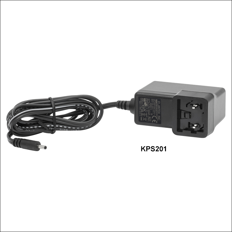
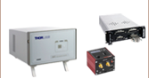
Click to Enlarge
電源ユニットKPS201(日本国内向けアダプタと共に発送します)
- 電源(単体)
- KPS201: K-Cubes™ 、T-Cubes™ 用、3.5 mmジャック付き
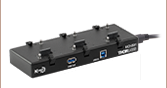
- 電源供給と通信機能を備えたUSBコントローラハブ
- KCH301: 3台までのK-CubeまたはT-Cube用
- KCH601: 6台までのK-CubeまたはT-Cube用
電源KPS201の出力電圧は+15 VDC、最大電流は2.66 Aで、3.5 mmジャックで1台のK-CubeまたはT-Cubeに電力を供給します。標準的な壁コンセントに接続して使用します。
USBコントローラーハブKCH301およびKCH601は次の2つの機能を有しています。1つはハブ機能で、最大3台(KCH301)または6台(KCH601)までのK-CubeまたはT-Cubeをサポートします。もう1つは電源機能で、標準的な壁コンセントに接続するだけで必要な電力の供給を行います。ただし、ハブが供給できる最大電流は10 Aです。お使いになる全Cubeの必要電流が合計で10 A以上にはならないことをお確かめください。 また、このハブに取り付けられたすべてのT-CubeやK-Cubeに対して、1本のUSBケーブルで接続することができます。
USBコントローラハブの詳細は、製品ページをご参照ください。