 Products Home / 自動(電動)ステージ / 電動直線移動ステージ(リニアステージ) / 電動直線移動ステージ(自動リニアステージ): 移動量25 mm / 小型電動直線移動ステージ(リニアステージ)、移動量25 mm
小型電動直線移動ステージ(リニアステージ)、移動量25 mm
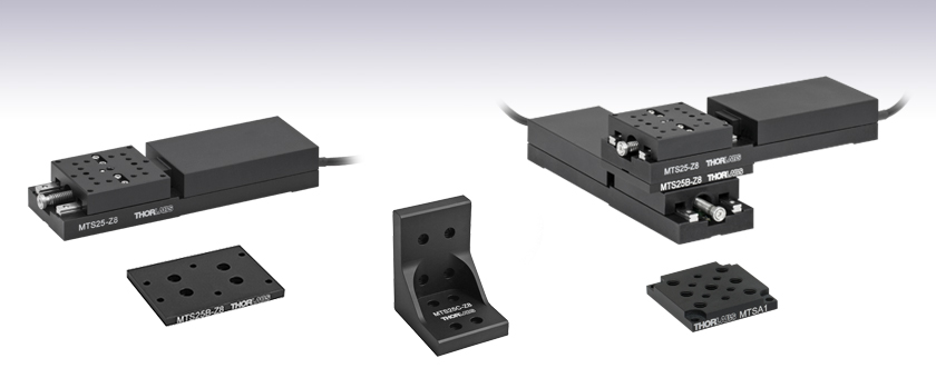
- 25 mm (0.98") of Travel in a Low-Profile Package
- 8-32 (M4 x 0.7) and 4-40 (M3 x 0.5) Tapped Holes
- Mounting Adapters for Breadboards, Multi-Axis Motion, and 60 mm Cage Systems
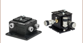
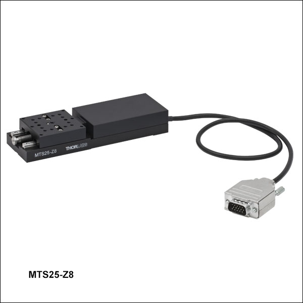
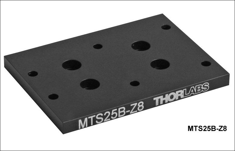
MTS25-Z8
25 mm Stage
MTS25B-Z8
XY Mounting Adapter
MTS25C-Z8
Right-Angle Bracket
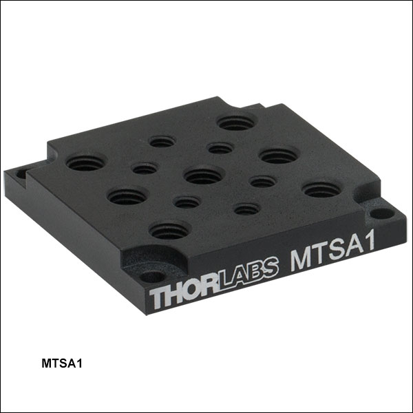
MTSA1
Accessory Mounting Plate
1/4"-20 (M6) and 8-32 (M4) Taps
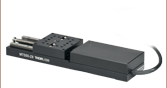
Application Idea
Two MTS25-Z8 Stages
in XY Configuration,
Using an MTS100B-Z8
Adapter Plate

Please Wait
| Key Specificationsa | |
|---|---|
| Travel Range | 25 mm (0.98") |
| Velocity (Max) | 2.4 mm/s |
| Min Achievable Incremental Movementb | 0.8 µm |
| Bidirectional Repeatabilityc | 1.6 µm |
| Backlashd | < 6 µm |
| Horizontal Load Capacity (Max) | 25 lbs (12 kg) |
| Vertical Load Capacity (Max) | 10 lbs (4.5 kg) |
| Included Actuator | Built-In DC Motor |
| Cable Length | 0.5 m (1.6 ft) |
| Required Controller | KDC101 |
特長
- 移動量:25 mm
- キャリッジは中心にM4タップ穴が1つとM3タップ穴が18個
- 薄型の筐体にアクチュエータと移動プラットフォームが統合
- DCサーボモーターアクチュエータ
- 数種類の取付けアダプタが利用可能
- ブレッドボードへの固定用のベースプレート
- 標準の光学アクセサリ用XY アダプタープレート(M6タップ穴が7個、M4タップ穴が6個付き)
- XY2軸ステージ構成用アダプタ
- 垂直方向の取付け用の直角ブラケット
- 60 mmケージシステム用アダプタ
当社の自動ステージMTS25/M-Z8は、特定の軸に沿った25 mmの直線移動を電子制御します。 各ステージには、37.5 mm x 37.5 mmの範囲にM3タップ穴が18個あり、中央にはM4タップ穴があります。
移動プラットフォームにはアライメント用のピン穴が付いているので、直交性を確保しつつステージを他のステージと積み重ねたり、アクセサリに接続したりすることができます。 ギアヘッド比67.49:1で、耐荷重は水平方向に12 kg、垂直方向に4.5 kgです。 内蔵されたホール効果エンコーダにより、分解能29 nmを実現します(詳細は「仕様」タブをご参照ください)。
2本の直線レールと連続的に再循環するボールベアリングに基づいた移動機構によって、滑らかで摩擦の少ない動きが可能になっています。 内蔵されたリミットスイッチによって、制御用インターフェイスを使用しなくても、想定範囲外の移動を防ぐことができます。
取付けアダプタとステージの組合せについて
当社のアダプタープレートおよびブラケットは、MTS25/M-Z8を光学テーブルやブレッドボードに取り付けたり、60 mmケージシステムの光軸に沿ってモータを取り付けたり、いくつかのステージを組み合わせてXY、XZ、またはXYZステージを構築したりする際に便利です。 M6タップ穴が7個、M4タップ穴が6個付いたアダプタープレートもご用意しています。このプレートは標準的な光学アクセサリを上部プラットフォームに取り付ける際に便利です。 移動量50 mmの電動移動ステージMTS50/M-Z8や移動量 100 mmのMTS100/M-Z8もMTS25/M-Z8と組み合わせてお使いいただくことができます。これらについては下記でご覧いただけます。
コントローラについて
このステージの駆動にはDCサーボモーターコントローラKDC101と15 V電源が必要です(別売り、下記参照)。 当社では、単品価格よりもお得な移動ステージMTS25/M-Z8、DCサーボコントローラKDC101、電源KPS101*のセットKMTS25E/Mもご用意しています。
当社では、取付け面が長く、より高い柔軟性をもつ電動移動ステージ PT1/M-Z9もご用意しています。
*こちらの電源は旧製品のため単体ではご購入いただけません。交換が必要な場合にはKPS201がご使用いただけます。
| Stage Specifications | |
|---|---|
| Translation | |
| Travel Range | 25 mm (0.98") |
| Repeatabilitya | 15 µm |
| Backlashb | <6 µm |
| Theoretical Min Incremental Movementc | 0.03 µm |
| Min Incremental Movementd | 0.8 µm |
| Accuracy | 60 µm |
| Homing Accuracy | ±4.0 µm |
| Motion Parameters | |
| Speed | 2.4 mm/s Max |
| Acceleration | 4.5 mm/s2 Max |
| Load Capacity | |
| Vertical Load | Recommendede: < 4.0 kg (< 8.8 lbs); Max: 4.5 kg (10 lbs) |
| Horizontal Load | Recommendede: < 10 kg (< 22 lbs); Max: 12 kg (25 lbs) |
| Straightness | |
| Pitch | 720 µrad |
| Yaw | 250 µrad |
| Motor Specifications | |
| Motor Type | DC Servo |
| Motor Drive Voltage | 6 VDC |
| Feedback | Hall Effect Encoder |
| Encoder Resolution | 29 nm |
| Encoder Counts per Lead Screw Revolution | 34,555 |
| Planetary Gear Head Ratio | 67.49:1 |
| Cable Length | 0.5 m (1.6 ft) |
| General Specifications | |
| Dimensions | 5.31" x 1.69" x 0.87" (134.8 mm x 43.0 mm x 22.0 mm) |
| Weight | 0.31 kg (0.68 lbs) |
分解能の計算
MTS25/M-Z8では、 モータ1回転当たり512回のエンコーディング(回転検出)を行います。モータの出力軸と遊星歯車ヘッドのギア比は67.49:1になっています。これは1.0mmピッチの送りネジが1回転するのにモータが67.49回転する必要があることを示しています。最終的に送りネジは1.0mmごと移動します。
エンコーディングごとの直線移動距離は以下のようになります。
送りネジ1回転毎のエンコーダカウントは、512 x 67.49 = 34,555
一方、1エンコーダカウント毎の送りネジの直線移動距離は
1.0 mm / 34,555カウント= 2.9 x 10⁻⁵ mm (29 nm)
モータ用コネクタ
D型、オス
| Pin | Description | Pin | Description |
|---|---|---|---|
| 1 | Ground/Return | 9 | Reserved for Future Use |
| 2 | Forward Limit Switch | 10 | Vcc |
| 3 | Reverse Limit Switch | 11 | Encoder A |
| 4 | Reserved for Future Use | 12 | Reserved for Future Use |
| 5 | Motor - | 13 | Encoder B |
| 6 | Reserved for Future Use | 14 | Ident |
| 7 | Motor + | 15 | Ident |
| 8 | Reserved for Future Use |
ソフトウェア
Kinesisバージョン1.14.52
XAバージョン1.0.0
KinesisおよびXAソフトウェアパッケージには、当社のモーションコントローラを制御するためのGUIが含まれています。
下記もご利用いただけます。
- 通信プロトコル

Figure 789AソフトウェアのGUI画面
当社では、様々なモーションコントローラを駆動するためのプラットフォームとして、XAソフトウェアパッケージと、今後段階的に終了していくKinesisソフトウェアパッケージの2種類をご用意しています。Kinesisソフトウェアは、当社の全てのモーションコントロール製品に対応しています。XAソフトウェアは開発者向けに改良されたプラットフォームですが、現在のところ定番のモーションコントロール製品の一部に対応している状況です(製品リストはこちらをご覧ください)。このソフトウェアは、継続して重点的に開発が進められており、最終的には当社の全てのモーションコントロール製品に対応する予定です。XAソフトウェアアプリケーションは、2040年までフルサポートを行います。
Kinesis モーションコントロールソフトウェア
Kinesisソフトウェアでは.NETコントロールを使用できるため、最新のC#、Visual Basic、LabVIEW™、あるいはその他の.NET対応言語を使用してカスタムプログラムを作成することができます。また、.NETフレームワークを使用しないアプリケーション用に、ローレベルのDLLライブラリも付属しています。中央シーケンスマネージャ(Central Sequence Manager)は、当社のすべてのモーションコントロール用ハードウェアの統合と同期をサポートしています。
この共通のソフトウェアプラットフォームにより、1種類のソフトウェアツールを習得するだけで、あらゆるKinesisコントローラを簡単に組み合わせて使用することができます。このように1軸システム用から多軸システム用までのあらゆるコントローラを組み合わせ、それら全てを1台のPCの統合されたソフトウェアインターフェイスから制御できます。
Click to Enlarge
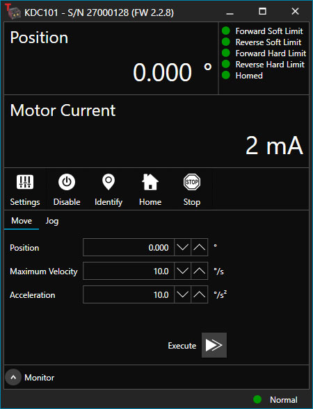
Figure 789B ブラシ付きDCサーボモーターコントローラKDC101用のXA GUI
このソフトウェアパッケージには2つの使い方があります。1つはGUI(グラフィカルユーザーインターフェイス)ユーティリティを用いる方法で、この場合はコントローラの到着後すぐに直接的な操作と制御を行なうことができます。もう1つは一連のプログラミングインターフェイスを用いる方法で、ご希望の開発言語によりカスタム仕様の位置決めやアライメント用のプログラムを簡単に作成することができます。
XAモーションコントロールソフトウェア:開発者向けに改良されたプラットフォーム
XAはその基本から理解しやすいように設計されており、スレッドセーフで言語パラダイムに依存しないC、C++、C#/.NETのアプリケーションプログラミングインターフェイスを提供します。また、ネイティブ、.NET言語、PythonまたはLabVIEWアプリケーションに簡単に統合できる言語ラッパーも用意されています。これは前述のKinesisにおけるソフトウェア開発キット(SDK)と同じ機能を果たす一方で、開発者に対してはより効率化されたツールキットを提供します。このソフトウェアは、付属の開発者用ガイドとSDK内のコード例を組み合わせて、複雑でカスタマイズされたアプリケーションとインターフェースを作成しようとするユーザー向けに設計されています。完全なAPIドキュメントはネイティブCライブラリ用に提供されており、.NETラッパーのドキュメントは現在開発中です。.NETラッパーの詳細については当社までお問い合わせください。
XAはKinesisと同等のGUIを備えているだけでなく、デバイスの状態を保存する機能の追加や、異なる種類のデバイス間インテーフェイスにおける一貫性の向上など、利用者のための様々な改善や工夫が実装されています。Kinesisソフトウェアは段階的に終了となりますが、XAは更に改善を進めるとともに、2040年までフルサポートしていく計画です。現行バージョンのXAソフトウェアは、まだ当社のモーションコントローラの一部にのみ対応している状況です。しかし、このソフトウェアは、継続して重点的に開発が進められており、最終的には当社の全てのモーションコントロール製品に対応する予定です。ソフトウェアの適合性に関する情報は、XAのユーザーガイドに記載されています。また、サポートしているデバイスのリストなど、ソフトウェアのその他の詳細情報はこちらをご覧ください。
電動リニアステージ
電動の直線移動ステージとしては、ピエゾ駆動の20 µm移動ステージからダイレクトドライブ方式の600 mm移動ステージまで、様々な最大移動量の製品をご用意しております。ステージの多くは、それらを用いてXY軸やXYZ軸などの多軸ステージを構築することができます。ファイバ結合用としては、多軸ステージのページをご覧ください。標準の電動ステージを用いるよりも精密な調整が可能です。直線移動ステージのほかに、電動の回転ステージおよびゴニオステージもご用意しております。また手動移動ステージもございます。
ピエゾステージ
これらのステージでは、様々な駆動機構にピエゾ素子が組み込まれています。ステージORIC®シリーズでは、「スティック-スリップ」と呼ばれる摩擦特性を利用したピエゾ慣性アクチュエータが用いられており、それにより長い移動距離が得られています。当社のモジュール式クイック接続型移動ステージXR25シリーズは、同じ原理で動作するピエゾ慣性アクチュエータPIA25で駆動できます。移動ステージNanoflex™シリーズは、手動アクチュエータに加えて標準的なピエゾアクチュエータが用いられています。ステージElliptec®シリーズでは共振ピエゾモータが用いられており、共振に伴うモータ先端の楕円形の動きで可動プラットフォームを押したり引いたりします。Z軸ステージLPS710E/Mにはピエゾ移動に対する機械的な増幅機構が組み込まれており、またそれに適したコントローラが付属しています。
| Piezoelectric Stages | ||||
|---|---|---|---|---|
| Product Family | ORIC® PDXZ1 Closed-Loop 4.5 mm Vertical Stage | ORIC® PD2 Open-Loop 5 mm Stage | ORIC® PDX2 Closed-Loop 5 mm Stage | ORIC® PDX4 Closed-Loop 12 mm Stage |
| Click Photo to Enlarge | 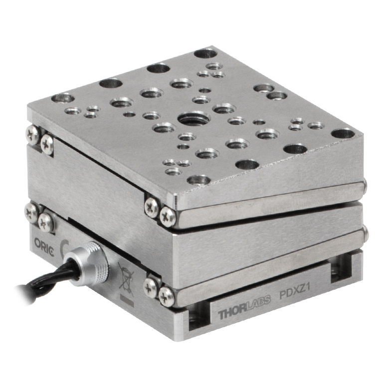 |  |  | 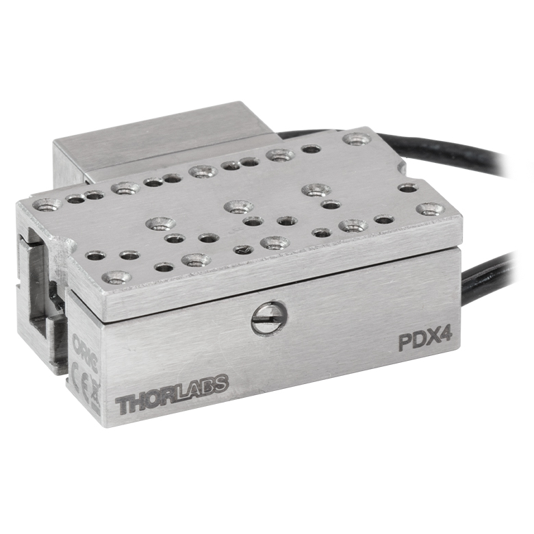 |
| Travel | 4.5 mm | 5 mm | 12 mm | |
| Speed | 1 mm/s (Typ.)a | 10 mm/s (Typ. Max)b | 8 mm/s (Typ.)c | 15 mm/s (Typ.)a |
| Drive Type | Piezoelectric Inertia Drive | |||
| Possible Axis Configurations | Z | X, XY, XYZ | ||
| Mounting Surface Size | 45.0 mm x 42.0 mm | 13.0 mm x 13.0 mm | 13.0 mm x 23.0 mm | |
| Additional Details | ||||
| Piezoelectric Stages | |||||||
|---|---|---|---|---|---|---|---|
| Product Family | ORIC® PD1 Open-Loop 20 mm Stage | ORIC® PD1D Open-Loop 20 mm Monolithic XY Stage | ORIC® PDX1 Closed-Loop 20 mm Stage | ORIC® PD3 Open-Loop 50 mm Stage | Compact Modular XRN25X 25 mm Stage | Modular XR25X 25 mm Stage | |
| Click Photo to Enlarge | 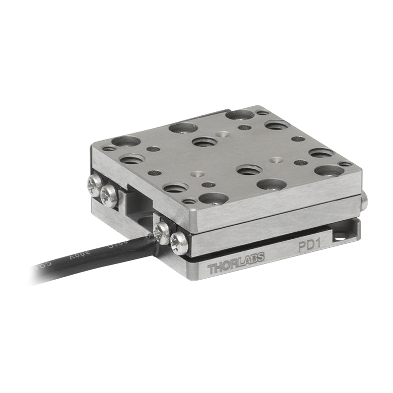 | 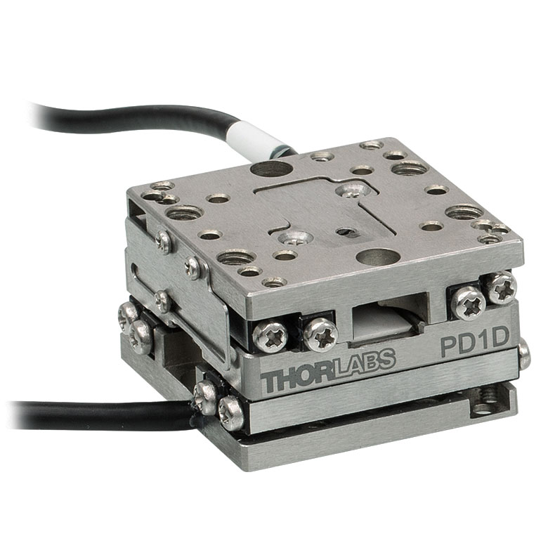 | 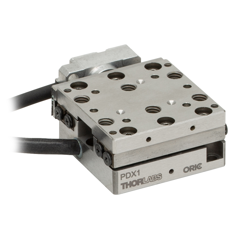 |  |  |  | |
| Travel | 20 mm | 50 mm | 25 mm | ||||
| Speed | 3 mm/s (Typ. Max)a | 20 mm/s (Typ. Max)b | 10 mm/sc | ≤3.6 mm/mind | ≤3.6 mm/mind | ||
| Drive Type | Piezoelectric Inertia Drive | ||||||
| Possible Axis Configurations | X, XY, XYZ | XY, XYZ | X, XY, XYZ | X, XY, XYZ | X, XY, YZ, XZ, XYZ | ||
| Mounting Surface Size | 30.0 mm x 30.0 mm | 80.0 mm x 30.0 mm | 85.0 mm x 50.7 mm | 110.0 mm x 75.7 mm | |||
| Additional Details | |||||||
| Piezoelectric Stages | ||||||
|---|---|---|---|---|---|---|
| Product Family | Nanoflex™ 20 µm Stage with 5 mm Actuator | Nanoflex™ 25 µm Stage with 1.5 mm Actuator | Elliptec® 28 mm Stage | Elliptec® 60 mm Stage | LPS710E 1.1 mm Vertical Stage | |
| Click Photo to Enlarge | 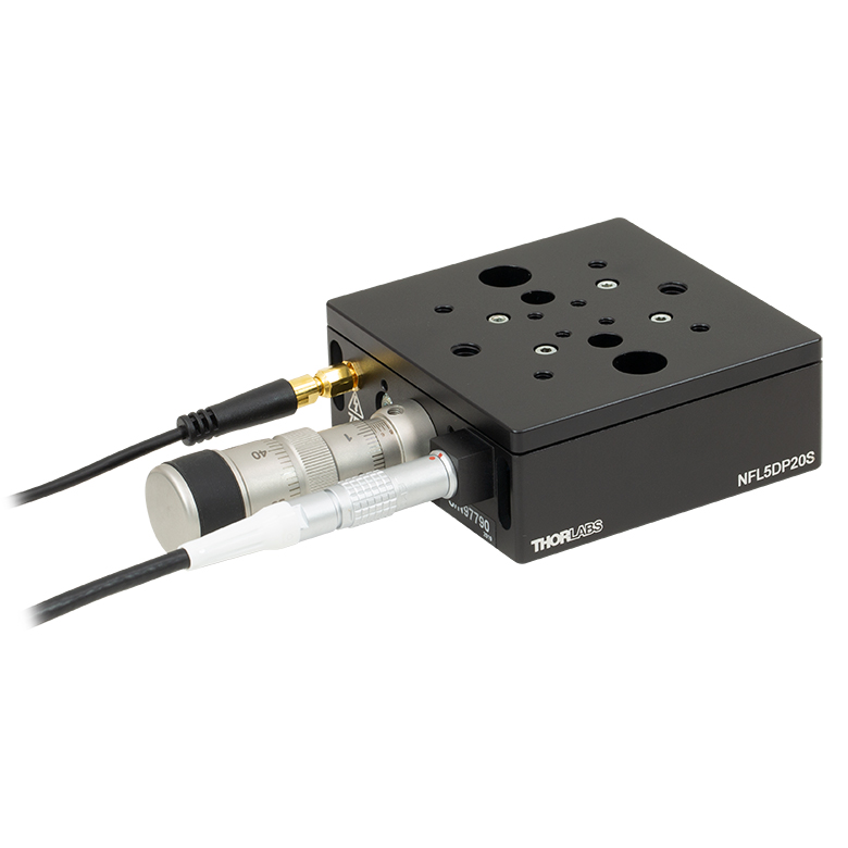 | 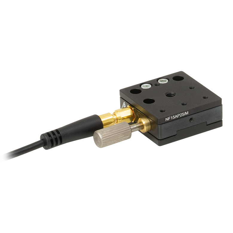 | 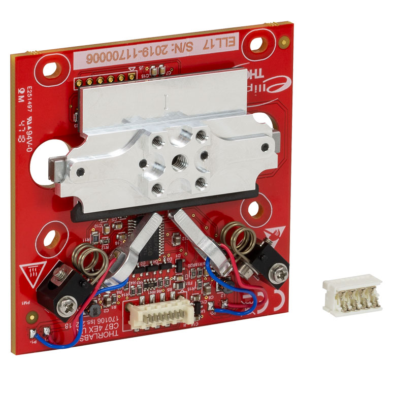 | 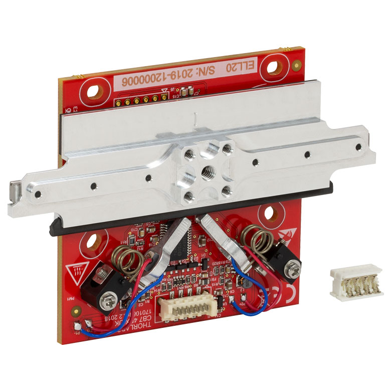 | 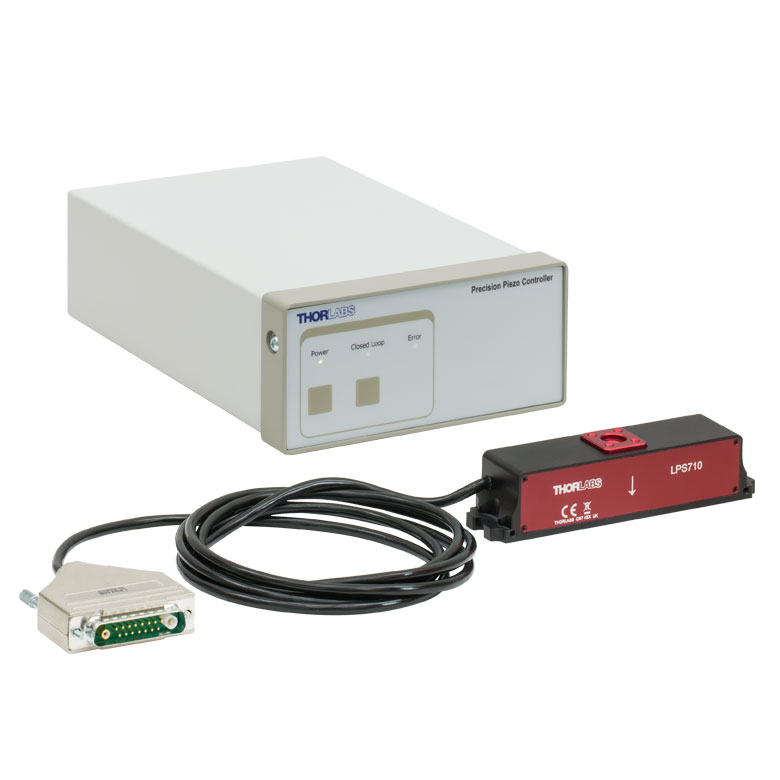 | |
| Travel | 20 µm + 5 mm Manual | 25 µm + 1.5 mm Manual | 28.0 mm | 60.0 mm | 1.1 mm | |
| Speed | - | 180 mm/s (Max) | 90 mm/s (Max) | - | ||
| Drive Type | Piezo with Manual Actuator | Resonant Piezoelectric Motor | Amplified Piezo | |||
| Possible Axis Configurations | X, XY, XYZ | X | Z | |||
| Mounting Surface Size | 75.0 mm x 75.0 mm | 30.0 mm x 30.0 mm | 15.0 mm x 15.0 mm | 21.0 mm x 21.0 mm | ||
| Additional Details | ||||||
ステッピングモーターステージ
こちらの移動ステージは脱着型あるいは内蔵型のステッピングモータを用いており、また300 mmまでの長い移動量が可能です。これらのステージの多くは多軸移動機能を有していたり(PLSXY)、あるいは多軸ステージを組み立てることが可能であったりします(PLSX、クイック接続型XR25シリーズ、LNRシリーズ、NRTシリーズ、LTSシリーズ)。ステージMLJ150/Mは高荷重にも対応する垂直移動ステージです。
| Stepper Motor Stages | |||||
|---|---|---|---|---|---|
| Product Family | MVSN1(/M) 13 mm Vertical Stage | PLS Series 1" Stages | Modular XR25 Series 25 mm Stage | LNR Series 25 mm Stage | LNR Series 50 mm Stage |
| Click Photo to Enlarge | 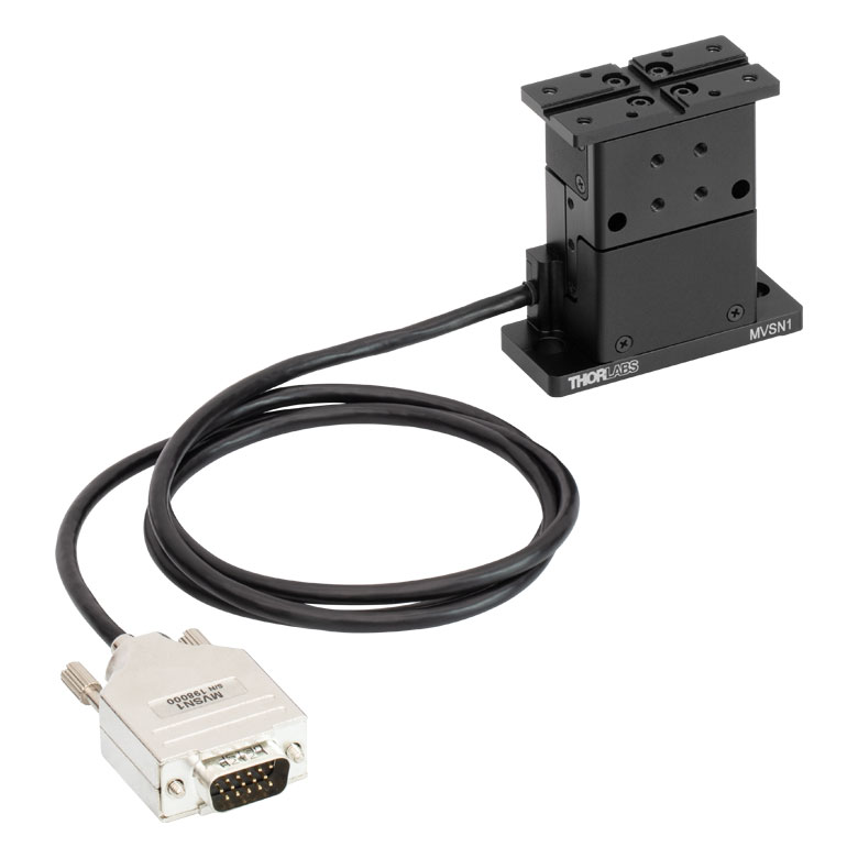 |  | 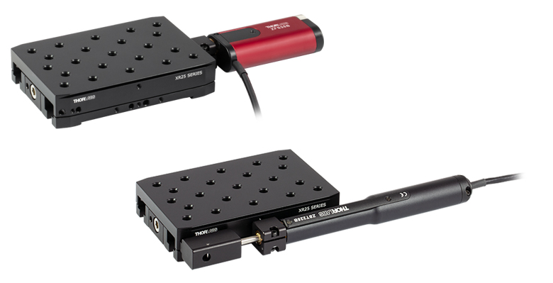 | 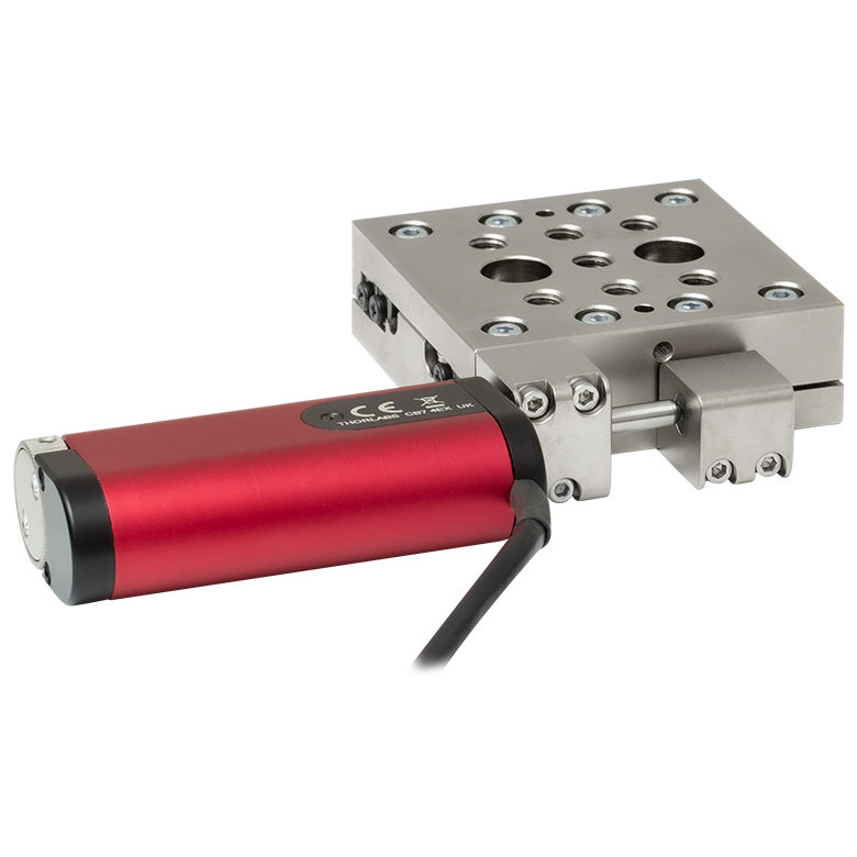 | 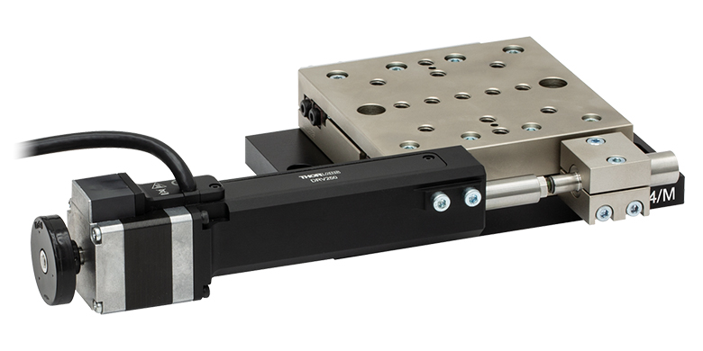 |
| Travel | 13 mm | 1" (25.4 mm) | 25 mm | 25 mm | 50 mm |
| Maximum Velocity | 5.0 mm/s | 7.0 mm/s | 2.0 mm/s | 2.0 mm/s | 50 mm/s |
| Possible Axis Configurations | Z | X, XY | X, XY, YZ, XZ, XYZ | X, XY, XYZ | X, XY, XYZ |
| Mounting Surface Size | 24.5 mm x 50.0 mm | 3" x 3" (76.2 mm x 76.2 mm) | 110.0 mm x 75.7 mm | 60 mm x 60 mm | 100 mm x 100 mm |
| Additional Details | |||||
| Stepper Motor Stages | ||||||
|---|---|---|---|---|---|---|
| Product Family | NRT Series 100 mm Stage | NRT Series 150 mm Stage | LTS Series 150 mm Stage | LTS Series 300 mm Stage | MLJ250 50 mm Vertical Stage | |
| Click Photo to Enlarge |  | 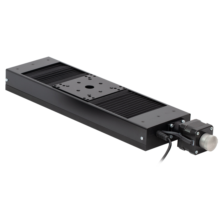 | 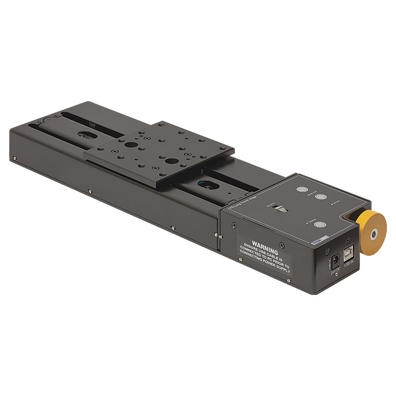 |  | 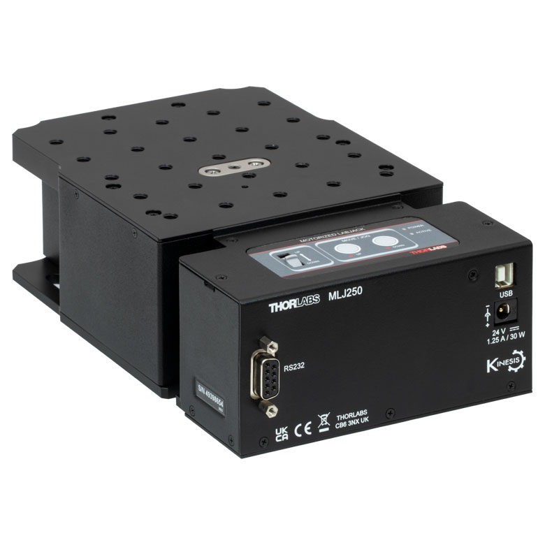 | |
| Travel | 100 mm | 150 mm | 150 mm | 300 mm | 50 mm | |
| Maximum Velocity | 30 mm/s | 50 mm/s | 3.0 mm/s | |||
| Possible Axis Configurations | X, XY, XYZ | X, XY, XYZ | Z | |||
| Mounting Surface Size | 84 mm x 84 mm | 100 mm x 90 mm | 148 mm x 131 mm | |||
| Additional Details | ||||||
DCサーボモーターステージ
脱着型あるいは内蔵型のDCサーボモータを用いた直線移動ステージをご用意しております。これらのステージは薄型で、多軸ステージの構築が可能です。
| DC Servo Motor Stages | ||||||
|---|---|---|---|---|---|---|
| Product Family | MT Series 12 mm Stages | PT Series 25 mm Stages | Compact Modular XNR25X 25 mm Stage | Modular XR25X 25 mm Stage | M30 Series 30 mm Stage | M30 Series 30 mm Monolithic XY Stage |
| Click Photo to Enlarge |  |  | 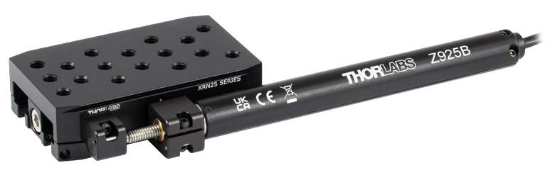 | 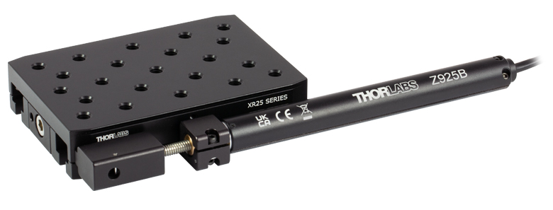 |  | 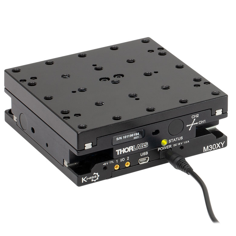 |
| Travel | 12 mm | 25 mm | 25 mm | 30 mm | ||
| Max Speed | 2.6 mm/s | 2.6 mm/sa | 2.4 mm/s | |||
| Possible Axis Configurations | X, XY, XYZ | X, XY, YZ, XZ, XYZ | X, Z | XY, XZ | ||
| Mounting Surface Size | 61.0 mm x 61.0 mm | 101.6 mm x 76.2 mm | 85.0 mm x 50.7 mm | 110.0 mm x 75.7 mm | 115.0 mm x 115.0 mm | |
| Additional Details | ||||||
| DC Servo Motor Stages | |||||
|---|---|---|---|---|---|
| Product Family | MTS Series 25 mm Stage | MTS Series 50 mm Stage | MTS Series 100 mm Stage | M150 Series 150 mm XY Stage | KVS30 30 mm Vertical Stage |
| Click Photo to Enlarge | 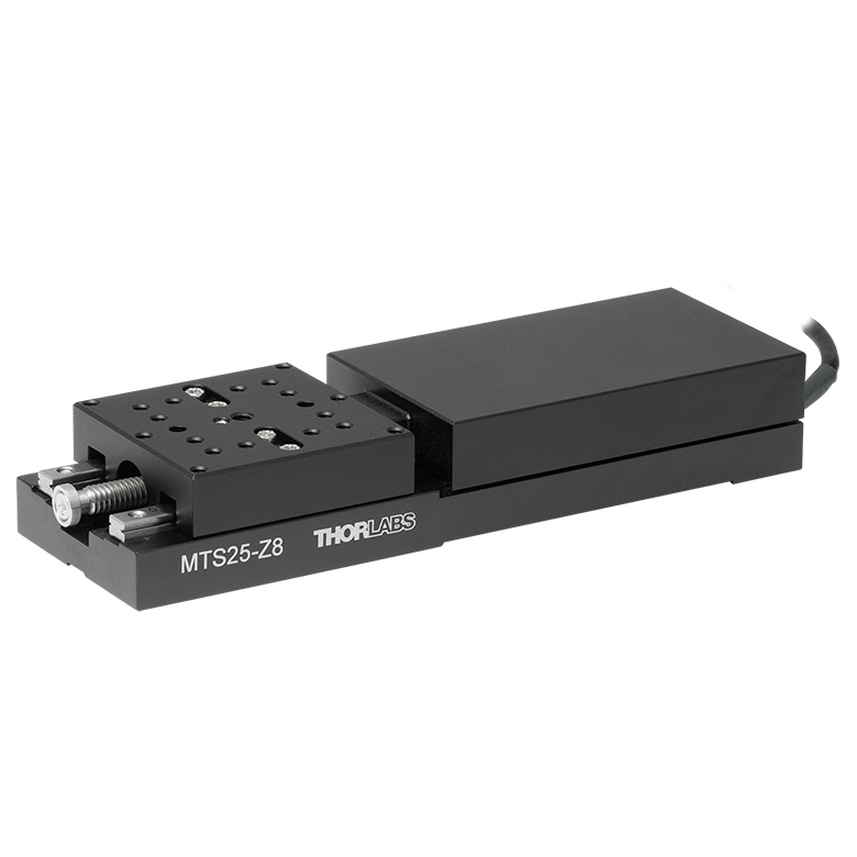 | 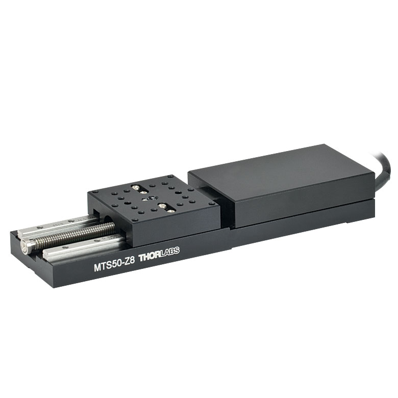 | 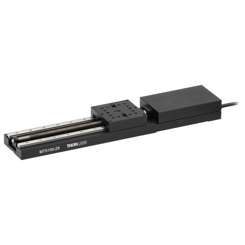 | 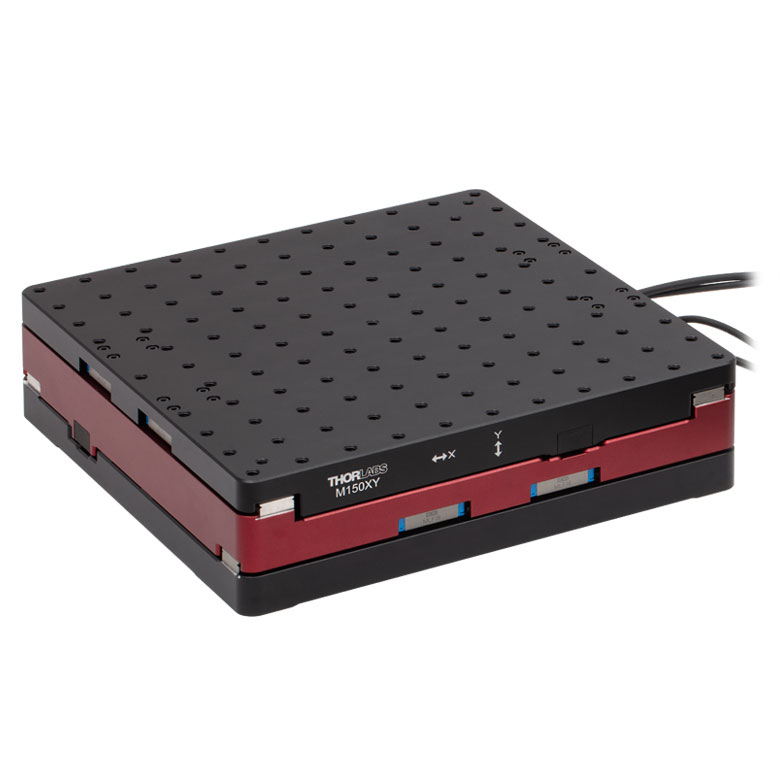 |  |
| Travel | 25 mm | 50 mm | 100 mm | 150 mm | 30 mm |
| Max Speed | 2.4 mm/s | X-Axis: 170 mm/s Y-Axis: 230 mm/s | 8.0 mm/s | ||
| Possible Axis Configurations | X, XY, XYZ | XY | Z | ||
| Mounting Surface Size | 43.0 mm x 43.0 mm | 272.4 mm x 272.4 mm | 116.2 mm x 116.2 mm | ||
| Additional Details | |||||
ダイレクトドライブステージ
こちらの薄型ステージにはブラシレスDCサーボモータが内蔵されており、バックラッシュの無い高速移動が可能です。電源が入ってないときは、ステージのプラットフォームにはほとんど慣性が無く、実質的にフリーラン状態になります。そのため電源が入ってないときにステージのプラットフォームが定位置に留まる必要のある用途には適していません。これらのステージを垂直方向に取付けることは推奨しません。
| Direct Drive Stages | |||||
|---|---|---|---|---|---|
| Product Family | DDS Series 50 mm Stage | DDS Series 100 mm Stage | DDS Series 220 mm Stage | DDS Series 300 mm Stage | DDS Series 600 mm Stage |
| Click Photo to Enlarge | 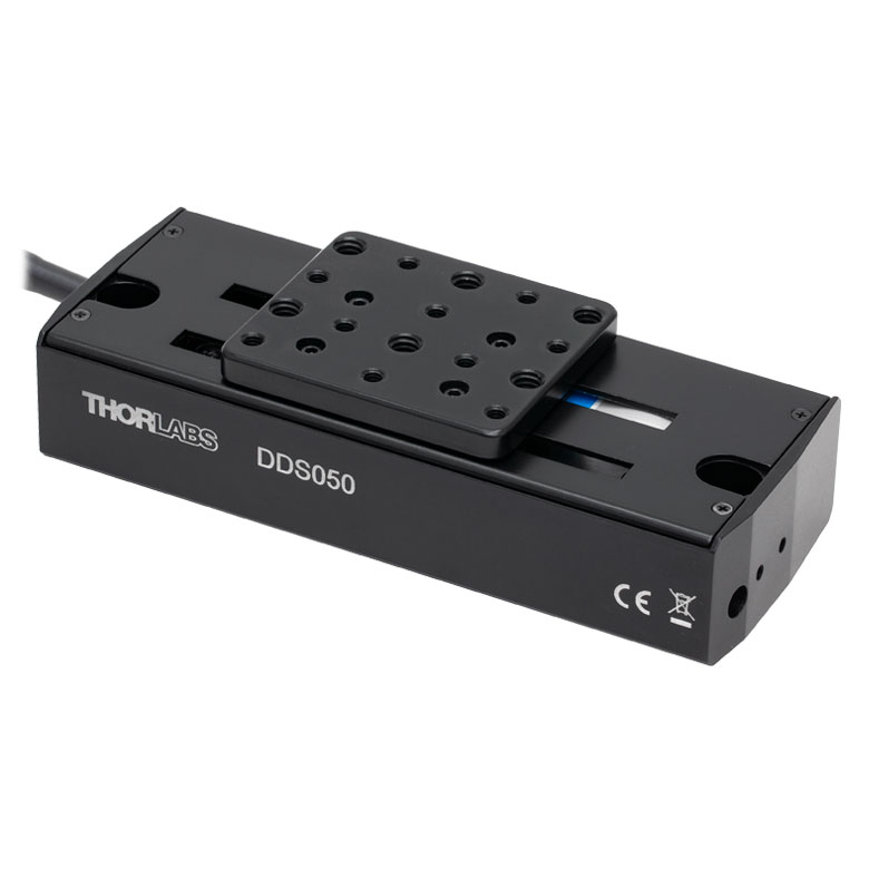 | 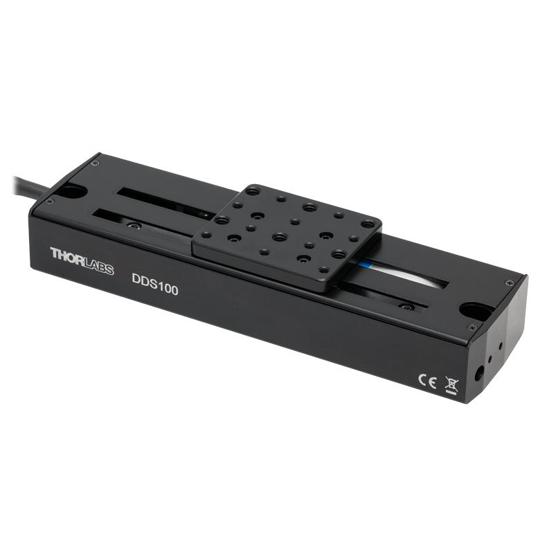 | 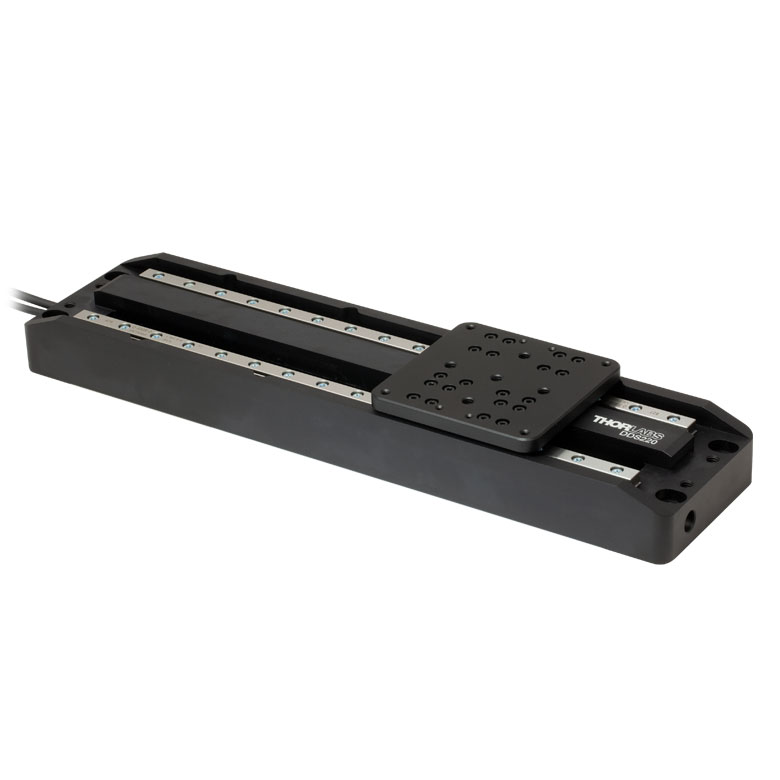 | 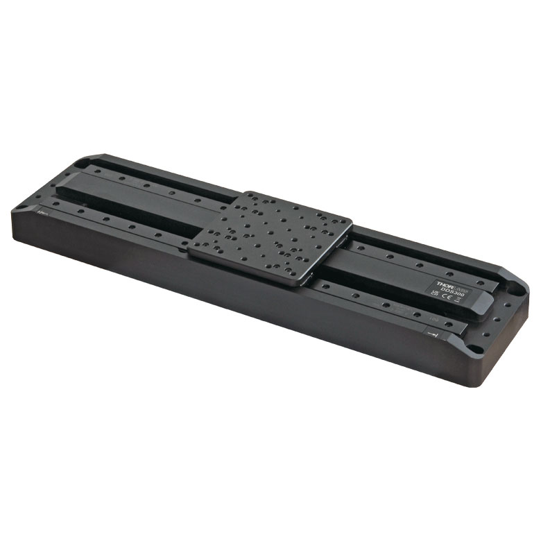 |  |
| Travel | 50 mm | 100 mm | 220 mm | 300 mm | 600 mm |
| Maximum Velocity | 500 mm/s | 300 mm/s | 400 mm/s | 400 mm/s | |
| Possible Axis Configurations | X, XY | X, XY | X | X | |
| Mounting Surface Size | 60 mm x 52 mm | 88 mm x 88 mm | 120 mm x 120 mm | ||
| Additional Details | |||||
| Posted Comments: | |
Emeric Biver
(posted 2024-06-25 10:37:06.593) 1- What is the default homing procedure and position for the MTS25/M-Z8 and a MTS50/M-Z8? Is it possible to change it (position AND procedure)?
2- Also, is it possible to override the limit switches to decrease the travel of the stages? (by implementing external limit switches and getting the controller to use these switches instead of the built-in ones)
3- Also, is it possible to define position 0 at the center of travel (if that's not already the case)?
For context, I am planning to buy a MTS25/M-Z8 and a MTS50/M-Z8 to implement an XY setup for a microscopy setting but the mechanical setup is such that if the MTS25/M-Z8 is at max or min of travel, the objective will crash into the sample holder. I need to use a stage with travel longer than 14 mm but shorter than 16 mm. spolineni
(posted 2024-07-01 06:37:28.0) Thank you for your feedback post. I will contact you directly to discuss your application and address your questions. Gülçin Ş. Aşkın
(posted 2024-01-29 21:37:32.657) Hello. I have two MTS25/M-Z8. One of them shows "Motor overcurrent" error in Home command. (Error code: 35002). Please let me know what can I check to resolve this issue. Best regards spolineni
(posted 2024-02-02 07:55:08.0) Thank you for reaching out to us. Regarding the issue you’re experiencing, it could be due to a variety of factors, typically something that impedes the movement of the stage. I will reach out to you directly to assist in troubleshooting and aim to resolve this issue. Dale Lossing
(posted 2023-01-24 15:38:10.853) We have several test benches with these linear stages and utilize Kinesis s/w to control them. On one of our set ups, the following occurs: Upon opening the Kinesis, it state "Loading to HID controllers" and there is a long pause then it does connect and works fine.
This is only happening on 1 of 4 setups. Separate computers on each. We updated the Kinesis s/w yesterday, no change. JReeder
(posted 2023-01-25 11:08:42.0) Thanks for your enquiry. The message 'Loading to HID Controllers' indicates that on that computer you have a Joystick or similar Human Interface Device connected which can be used to control the stage through our Kinesis software. This message indicates that it is loading the device into Kinesis so that you can use it. The message does not indicate an issue with the stages, controllers or software. user
(posted 2022-10-06 19:30:43.83) Hi
I purchased MTS25-z8/M before 5 years, and It still work well.
However, the moving stage oscillate much when it is moving.
Is there any way to reduce this oscillation?
Thank you for your reading. cwright
(posted 2022-10-06 11:54:04.0) Response from Charles at Thorlabs: Thank you for your query. There could be a few potential causes, such as wear to the lead screw or rails, should it have been used while lacking in grease, or the lead screw could have been bent by an impact. I will reach out to who to help with troubleshooting this. Pedro Garcia
(posted 2022-08-23 18:49:40.567) Regards, Thorlabs team:
I'm interested in the calibration file of the KDC101 K-Cube DC Servo Motor Controller, also I´ve experience some trouble trying to upgrade the software and firmware for this controller, there is some tutorial or instructions page? so I can corroborate that steps I've been follow are the proper method to this upgrade
Beforehand, I´m thankfull for your response DJayasuriya
(posted 2022-08-24 07:09:53.0) Thank you for your inquiry. Unfortuantely we do not have a guide, however we have reached out to you with how to update your firmware. Jisoo Kyoung
(posted 2021-10-27 22:20:44.793) Dear Thorlabs,
Hi, I am interested in your KMTS25E/M.
I would like to control the KMTS25E/M by Python code.
Is it possible to use Python instead of Kinesis Software?
If you have any example code, please send me.
Thanks. Jean-Baptiste Le Bouquin
(posted 2020-09-12 04:44:12.79) Hello, what is the operational ambiant temperature for the MTS25/M-Z8. We consider a use case in a telescope where ambiant temperature can vary from 5degC to 20degC. Thanks. DJayasuriya
(posted 2020-09-14 09:21:43.0) Thank you for inquiry. The unit would be functional within the temperature range 5 deg C to 40 deg C. Please note that if the unit has been stored at a low temperature or in an environment of high humidity,
it must be allowed to reach ambient conditions before being powered up. Hope this helps. Jean-Baptiste Le Bouquin
(posted 2019-10-14 14:31:05.527) Hi, How is it possible to control the KMTS25E with a Linux computer ? Ideally we need to control the translation stage with a serial communication. Thanks, Jean-Baptiste rmiron
(posted 2019-10-15 06:17:42.0) Response from Radu at Thorlabs: Hello, Jean-Baptiste. That is possible. You will need to refer to the serial protocol's documentation, which can be found here: https://www.thorlabs.com/Software/Motion%20Control/APT_Communications_Protocol.pdf
If have an RS-232 port on your PC, you can simply connect to the KDC101 controller via an RS-232 to USB cable. If not, you can set the relevant USB port as a virtual communications port. In order to do so, access DeviceManager, identify "APT USB Device" under "Universal Serial Bus controllers", right-click on it, go to Properties\Advanced and tick "Load VCP". If you now power-cycle the device, you should see a new port appear under "Ports".
Having done this, you should set the port settings as described on page 29 of the documentation. The device to real unit conversion ratios can be found on page 35. On pages 8-9 you can find the list of serial commands that you can send to your controller. If you require further assistance, please contact your local technical support team, who will gladly help. dale.durand
(posted 2016-11-30 15:25:52.397) I am using an MTS25-Z8 linear stage and TDC001 controller from LabView. It is working and I can command the stage to absolute positions. Where can I get descriptions of the move parameters; fMinVel, fAccn, and fMaxVel? It seems fMaxVel is the maximum velocity in mm per second. Why is there a minimum velocity? Are the units for fAccn mm/sec^2?
Thank you,
Dale Durand bhallewell
(posted 2016-12-07 04:42:13.0) Response from Ben at Thorlabs: When using APT, these parameters are set for real world units, in your case mm/sec & mm/sec^2. A description of these parameters can be found in the Motor Control Methods section of the APTServer help file & copied here. These are limited by the values we spec in the stage manual & on the website.
fMinVel - the minimum velocity at which to start and end a move (which we define as 0 in all cases).
fAccn - the rate at which the velocity climbs from minimum to maximum
slows from maximum to minimum.
fMaxVel - the maximum velocity at which to perform a move.
For Kinesis, this depends upon which method was used to set the velocity parameters of your device setup. In the .NET_API help file, we reference SetMoveRelativeDistance_DeviceUnit & SetMoveRelativeDistance, which enables the user to set velocities based on device encoder units (as defined in our communication protocol) & real world units respectively. stone4
(posted 2015-01-12 11:24:13.407) The TDC001 single cube PS has a plug on the bottom side. There is no reference to this in the manual. Can you provide details as to the function and use of this port? Also, how far can the TDC001 and Control computer be spaced? Can the system use a USB - RJ45 ethernet bride to position them farther than a powered USB extender? Thanks for your help. Cheers G Stone - stone4@llnl.gov msoulby
(posted 2015-01-13 11:14:22.0) Response from Mike at Thorlabs: The port on the bottom of the TDC001 is for when it is used with our TCH002 T-cube control hub. Up to six cube can all be powered on the hub without the need for additional USB or power cables. If using the T-cube as a standalone item then we would recommend not using a USB cable that is any longer than a couple of meters to avoid any communication problems with the PC. However if you do need to extend the cable then we would recommend using a powered USB hub to do this. dodge.charger.r.t.69
(posted 2014-03-04 21:46:15.517) I am controlling a MTS25/M-Z8E stage via LabView and noticed the reverse movement specified by a displacement of say 10um from 2000um overshoots the desired mark(1990um) by a random value (say 50um thus reaching 1940um)and then the stage travels forward again to the 1990um mark. How can i rectify it? Solution would be of really great help. Thanks msoulby
(posted 2014-03-06 10:05:39.0) Response from Mike at Thorlabs: This extra movement is caused by the backlash correction setting; this backlash correction is designed to make sure that all positions are approached from one direction which has the effect of improving the overall repeatability of the stage. The default correction amount for the MTS25/M-Z8E is 0.050mm (50um) which matches the effect you are observing. To remove backlash correction you can simply set this setting to ZERO in either the APT user settings or by calling the ActiveX method SetBLashDist. twizypivo89
(posted 2014-01-08 21:52:36.917) I am planning to purchase a MTS25/M-Z8 stage and to know if the product would be suitable for me, I would like to know the minimum achievable speed of movement of the stage (linear speed of the stage). Thanks. msoulby
(posted 2014-01-09 06:16:06.0) Response from Mike at Thorlabs: The minimum velocity value you can enter for the MTS50-Z8 is limited by the APT software code, so the smallest value you can enter and still get movement is the minimum velocity, which is about 40um/s. Also at these velocities the velocity may not be as stable as at higher velocities and the motion be jumpy and not smooth. If you need high resolution sub-micron positioning you would get better results using a piezo actuated stage or a direct drive linear stage such as the DDS220/M. hadi.abidin
(posted 2013-04-22 12:40:00.75) How will this linear stage perform when mounted vertically under low vacuum(100mbar). Can you provide a quotation for a vacuum version of this stage tcohen
(posted 2013-04-25 11:09:00.0) Response from Tim at Thorlabs: The stage itself should be fine for this low vacuum. The motor, however, would likely require adding vacuum compatible greases. We will contact you with a quotation. jlow
(posted 2012-12-27 11:11:38.363) Response from Jeremy at Thorlabs: It could be that the velocity and acceleration settings are set too low. I will get in contact with you directly to discuss about this. ggjmlee
(posted 2012-12-26 18:54:28.867) I bought two MTS25/M-Z8s' with controllers. When I bought them, they moved fast. But moving speed of them has slowed down now. Could you let me know any possible causes and how to solve this problem? I like to move the stage faster as when I bought them.
Thanks tcohen
(posted 2012-06-13 09:16:00.0) Response from Tim at Thorlabs: Thank you for your feedback! I will contact you directly to discuss your measurements and operating conditions to determine the performance of your stage and provide support. aboudreault
(posted 2012-06-07 15:30:53.0) Hello, recently we have bought two motorized stages, a MTS25 and a MTS50. The MTS25 respect the spec for bidirectional repeatability and home location accuracy but the MTS50 is less good. Instead to have bidirectional of 1.6um it is more like 5 or 6um and the home location accuracy is around 25um. Do you have an idea why my MTS50 is less good. bdada
(posted 2011-07-18 12:07:00.0) Response from Buki at Thorlabs:
Our motion control products use APT software, which use ActiveX control for various programming environments such as LabVIEW. We have some tutorials online available to help you get started. You can find them at:
http://www.thorlabs.de/images/TabImages/GuideToLabVIEWandAPT.pdf
http://www.thorlabs.de/tutorials/Intro.cfm
You can also download the APT software package at http://www.thorlabs.de/software_pages/ViewSoftwarePage.cfm?Code=APT and run it in simulation mode to get familiar with the software.
Please contact TechSupport@thorlabs.com if you have further questions luis.ferreira
(posted 2011-07-15 17:12:58.0) Is it possible to provide LabView Drivers for these translators ? bdada
(posted 2011-04-26 12:00:00.0) Response from Buki at Thorlabs:
Thank you for your feedback. A position error of 3mm is much higher than normal. We will contact you directly to get your serial number. In the meantime, please check that you have set up the APT config programme to the correct stage type. sema
(posted 2011-04-26 05:33:37.0) I am using the MTS25 with a t-cube controller. For a 10 mm step entered in the software, I get approx. 7 mm actual translation. Can that be corrected with a calibration file? If so, can I do the calibraiton myself, or where do I get such a file? |

 ズーム
ズーム
Click to Enlarge
ミリ規格製品の概略図
Click to Enlarge
インチ規格製品の概略図
- 25 mm移動のDCサーボモーターアクチュエータ内蔵
- M4タップ穴が1つとM3タップ穴が18個
- 単体、もしくはコントローラKDC101および電源KPS101*とのセットでご提供
当社の電動移動ステージMTS25/M-Z8は、1軸方向への直線移動が可能です。中央にある1つのM4タップ穴および、18個のM3タップ穴を利用して、オプトメカニクス製品を移動プラットフォームに直接取り付けられます。 2本の直線レールと連続的に再循環するボールベアリングに基づいた移動機構により、滑らかで摩擦の少ない動きが可能になっています。
移動ステージの操作にはコントローラと電源が必要ですが、当社が推奨するK-Cube® モーターコントローラKDC101と電源について、詳細は下記をご覧ください。ステージ、DCサーボモーターコントローラKDC101および電源KPS101*をセットでもご用意しており、個別にお買い求めいただくよりお得になっております。 電源は、日本で使用できる仕様でお届けいたします。 日本対応以外の電源アダプタをご希望の場合には、ご注文前に当社までお問い合わせください。
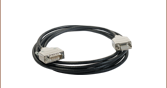
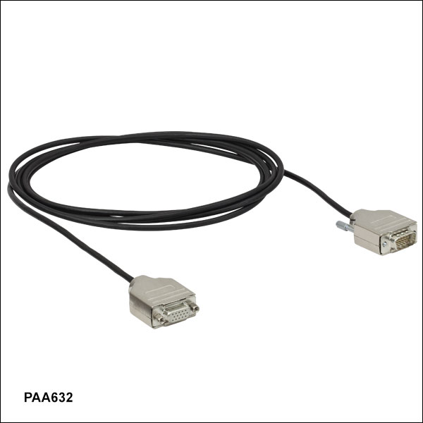
ステージに組み込まれている駆動ケーブルの長さは0.5 mです。さらに長いケーブルが必要な場合は延長ケーブルPAA632(2.5 m)のご使用をお勧めいたします。 延長ケーブルはこのページの最後に記載しております。
*こちらの電源は旧製品のため単体ではご購入いただけません。交換が必要な場合にはKPS201がご使用いただけます。

 ズーム
ズーム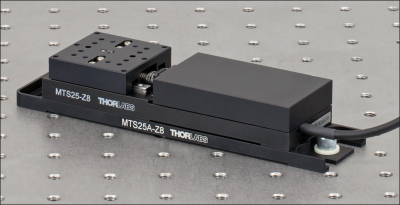 Click to Enlarge
ベースプレートMTS25A-Z8を用いてブレッドボードに取り付けたMTS25(/M)-Z8
- ステージMTS25/M-Z8を光学テーブルやブレッドボードに取り付け
- 4個のM6ネジ用ザグリ穴
- 取り付けに必要なネジ、および平行度を維持するためのアライメント用のピンが付属
ベースプレートMTS25A-Z8に付いている4個のM6用のザグリ穴スロットを利用して、プレートに取り付けたMTS25/M-Z8をブレッドボードに固定することができます(右の写真参照)。 移動ステージは、ベースプレートに4個のM3キャップスクリュを使用して接続します。 2個のアライメント用ピンを使用することにより、移動軸がプレートの長さ方向に対してしっかりと平行になります。

 ズーム
ズーム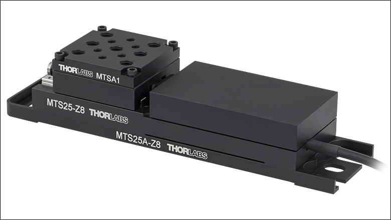 Click to EnlargeステージMTS25(/M)-Z8に取り付けられたアダプタープレートMTSA1(/M)
- 標準的な光学アクセサリを取付け可能
- 7つのM6取付け穴と6つのM4取付け穴付き
- 取付けに必要なネジが付属
アダプタープレートMTSA1/Mは、4隅にある貫通穴と4つのネジ(付属)を利用してMTS25/Mステージの上部プラットフォームに取り付けることができます。 7つのM6取付け穴と6つのM4取付け穴を配列しているので、汎用アクセサリや汎用部品と共にお使いいただければより多くの取付けオプションに対応可能です。アダプタープレートおよびベースプレート取付け後のステージの作業高さは7.5 mmです。 プレートには反射を抑える黒色アルマイトコーティング仕上げが施されています。

 ズーム
ズーム Click to Enlarge
Two MTS25-Z8 Stages Stacked in an XY Configuration Using an MTS25B-Z8 Adapter
| Max Load on Top Stage | |
|---|---|
| Top Stage | Max Loada |
| MTS100(/M)-Z8 | 2.2 lbs (1 kg) |
| MTS50(/M)-Z8 | 3.7 lbs (1.7 kg) |
| MTS25(/M)-Z8 | 10 lbs (4.5 kg) |
- Stack Two MTS25(/M)-Z8 Stages in an XY Configuration
- Includes All Necessary Mounting Hardware and Alignment Pins for Orthogonality
The MTS25B-Z8 XY Adapter Plate is designed to orient two MTS25(/M)-Z8 stages orthogonally in the XY plane, as shown in the photo to the right. This plate may also be used to mount an MTS25(/M)-Z8 stage on top of our 50 mm (1.97") MTS50(/M)-Z8 stage or 100 mm (3.94") MTS100(/M)-Z8 stage.
To begin the assembly process, fasten the plate to the top of the lower stage using four of the provided 4-40 or M3 cap screws. Then insert the provided alignment pins. To complete the assembly, use the remaining 4-40 or M3 cap screws to fasten the plate to the bottom of the upper stage.
Thorlabs' MTS50(/M)-Z8 stage or MTS100(/M)-Z8 stage can also be mounted on top of an MTS25(/M)-Z8 stage in an XY configuration using the MTS50B-Z8 or MTS100B-Z8 adapter plates, respectively. Note that when using an MTS50(/M)-Z8 or MTS100(/M)-Z8 stage on top, the max load on the top stage is reduced to 3.7 lbs (1.7 kg) or 2.2 lbs (1.0 kg), respecitvely, due to stage torque over the travel range.

 ズーム
ズーム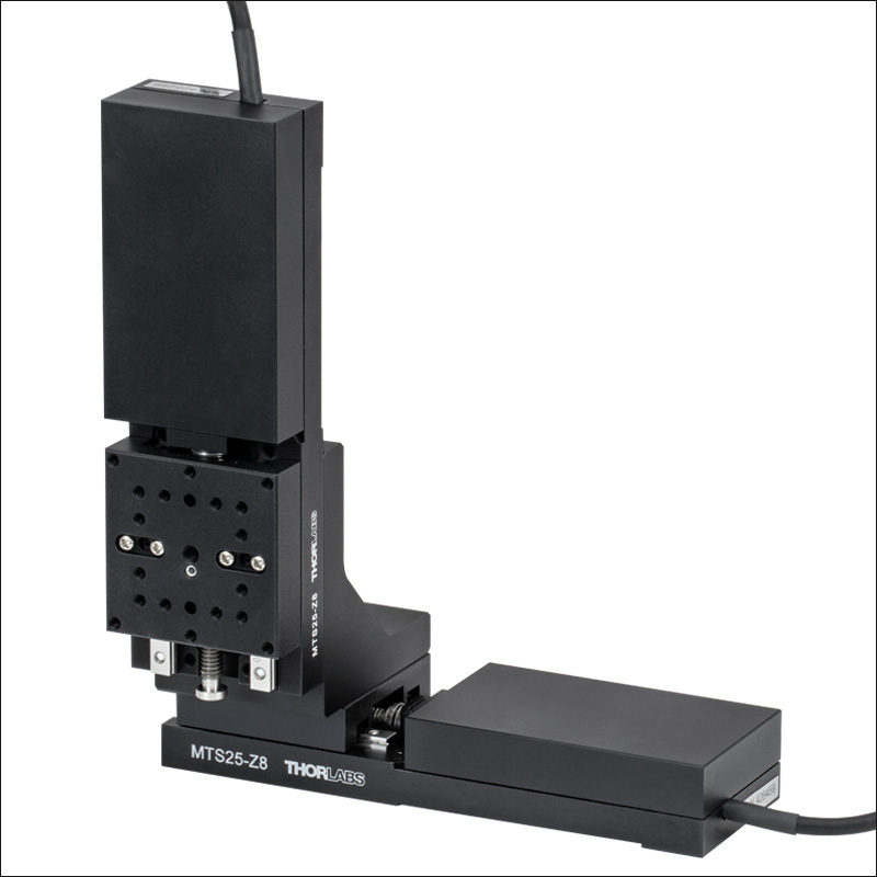 Click to Enlarge
直角ブラケットMTS25C-Z8を使用してXY構成にした2つのステージMTS25(/M)-Z8
- 移動ステージMTS25/M-Z8を垂直に取り付け可能
- XZ、XYZステージ構築用に設計
- 取り付けに必要なネジ、および直交設置用のアライメントピンが付属
直角ブラケットMTS25C-Z8を用いて、ステージMTS25/M-Z8を縦軸方向に取り付けることができます。 このブラケットは、複数のステージMTS25/M-Z8をXZまたはXYZに構成する際に必要となります。 このブラケットを利用して当社の移動量50 mmのステージMTS50/M-Z8や移動量100 mmのステージMTS100/M-Z8と移動量25 mmのステージMTS25/M-Z8を組み合わせることもできます。
右図のようなXZ構成を構築するには、付属の2本のアライメント用ピンを水平に置いたステージに挿入します。 次に、付属の4つのM3キャップスクリュを使用して水平に置いたステージ上面にブラケットを固定します。 さらに残りの2本のアライメントピンを垂直取付け面に挿入します。 最後に残りのキャップスクリュを使用して垂直側のステージをブラケットに取り付けます。
XYZ構成を構築する際には、先にXY構成を構築し、前述のステップに倣ってステージとブラケットを取り付けてください。

 ズーム
ズーム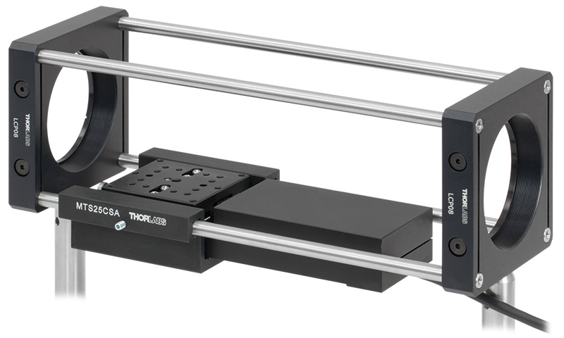 Click to Enlarge
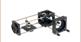
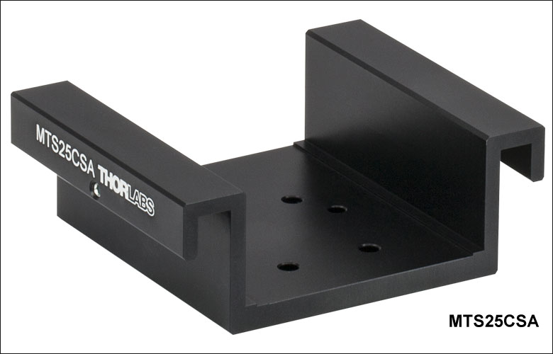
- 60 mmケージシステムに移動ステージMTS25/M-Z8を取付け
- 組み立てる際にケージシステムを分解する必要がありません
- 取付けに必要なネジ、および平行度を維持するためのアライメント用のピンが付属
アダプタープレートMTS25CSAを60 mmケージシステムに組み込むことで、ステージMTS25/M-Z8を光軸と平行に設置することができます。 これによりケージシステム内の光学素子は25 mmの範囲で移動することができます。 ステージを取り付けるために必要なケージロッドの長さは159 mmです。 MTS25CSAの利用例は右の写真をご覧ください。
取付けには、まず付属の2つのアライメントピンをステージの底面に挿入してください。 次に、付属の4つのM3キャップスクリュを使ってアダプタをステージに固定します。 この時点で、アセンブリはケージロッドを介して光学系に固定されています。 最後に2つのナイロンチップ付き止めネジ(セットスクリュ)を締めてロッドを固定します。

 ズーム
ズーム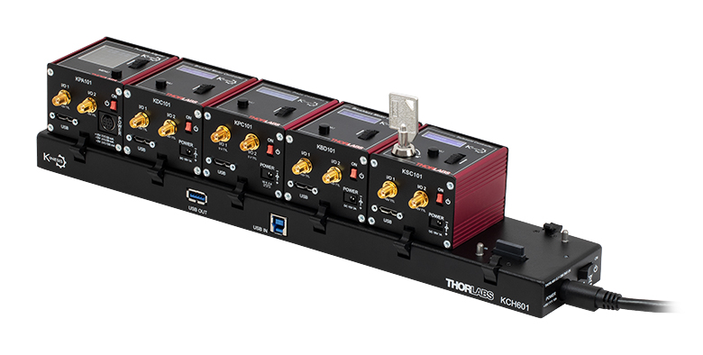 Click to Enlarge
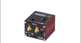
Figure 779A K-Cube®モジュールを取り付けたUSBコントローラーハブKCH601(別売り)
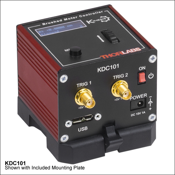
- 前面パネルに電動ステージやアクチュエータ制御用の速度ホイールとデジタル表示画面
- 2つの双方向トリガーポート(外部機器からの信号読み取りや外部機器の制御用)
- 付属のUSBケーブルでPCに接続
- KinesisおよびXAソフトウェアに完全対応
- コンパクトな設置面積:60 mm x 60 mm x 49.2 mm
- 電源は付属しません(下記参照)
当社のK-Cube®ブラシ付きDCモーターコントローラKDC101は、1台のモータの回転軸を手動またはPCで制御します。上面のコントロールパネルには速度ホイールがあり、位置のプリセットに加えて、順方向ならびに逆方向のジョグ動作と双方向の4段階速度制御が可能です。上面パネルのデジタル表示にはバックライトが付いており、メニュー選択により暗くしたり消灯したりすることが可能です。ユニット前面には双方向のトリガーポートが2つあり、5 Vの外部ロジック信号を読み取ることや、5 Vロジック信号を出力して外部機器を制御することができます。それぞれのポートの機能は独立に設定することができます。
このユニットは当社の新しいKinesisとXAソフトウェアパッケージに対応します。詳細は「KinesisならびにXAソフトウェア」のタブをご覧ください。
このコントローラには電源が付属しませんのでご注意ください。対応可能な電源は下記のとおりです。詳細はDCサーボモーターコントローラKDC101の製品紹介ページでご覧ください。

 ズーム
ズーム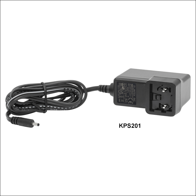
Click to Enlarge
Figure 780A 電源ユニットKPS201(日本国内向けアダプタと共に発送します)
- 電源(単体)
- KPS201: K-Cube®、T-Cubes™ 用、3.5 mmジャック付き
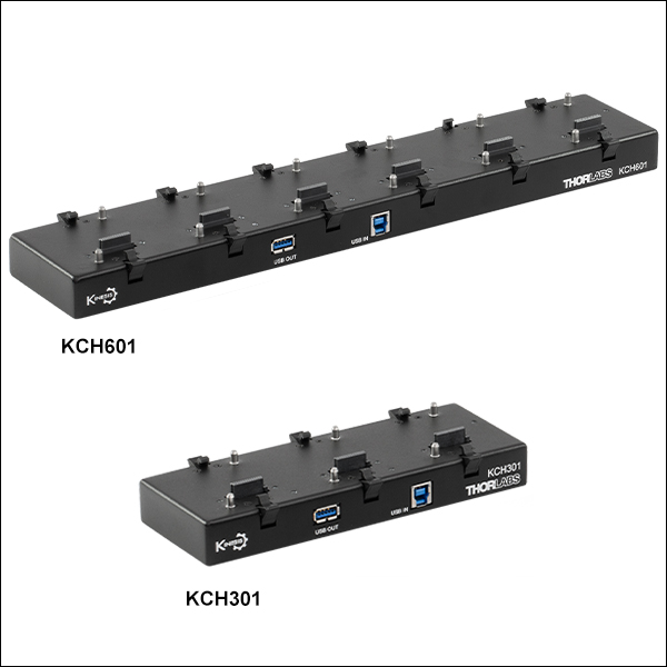
- 電源供給と通信機能を備えたUSBコントローラハブ
- KCH301: 3台までのK-CubeまたはT-Cube用
- KCH601: 6台までのK-CubeまたはT-Cube用
電源KPS201の出力電圧は+15 VDC、最大電流は2.66 Aで、3.5 mmジャックで1台のK-CubeまたはT-Cubeに電力を供給します。標準的な壁コンセントに接続して使用します。
USBコントローラーハブKCH301およびKCH601は次の2つの機能を有しています。1つはハブ機能で、最大3台(KCH301)または6台(KCH601)までのK-CubeまたはT-Cubeをサポートします。もう1つは電源機能で、標準的な壁コンセントに接続するだけで必要な電力の供給を行います。ただし、ハブが供給できる最大電流は10 Aです。お使いになる全Cubeの必要電流が合計で10 A以上にはならないことをお確かめください。 また、このハブに取り付けられたすべてのT-CubeやK-Cubeに対して、1本のUSBケーブルで接続することができます。
USBコントローラハブの詳細は、製品ページをご参照ください。

 ズーム
ズーム延長ケーブルPAA632の長さは2.5 mで、コネクタは当社の電動式アクチュエータ製品すべてに使用できる15ピンD‑サブコネクタです。 オス型のケーブル端はコントローラに、メス型はモータに接続します。