 Products Home / 自動(電動)ステージ / 電動直線移動ステージ(リニアステージ) / ORIC® 20 mm Linear Translation Stage with Ultrasonic Piezoelectric Drive
ORIC® 20 mm Linear Translation Stage with Ultrasonic Piezoelectric Drive

- Linear Ultrasonic Piezo Stage with Closed-Loop Positioning
- 3 kg Horizontal Load Capacity
- Typical Max Speed Up to 100 mm/s
- Stackable Design for Compact 1-, 2-, or 3-Axis Setups
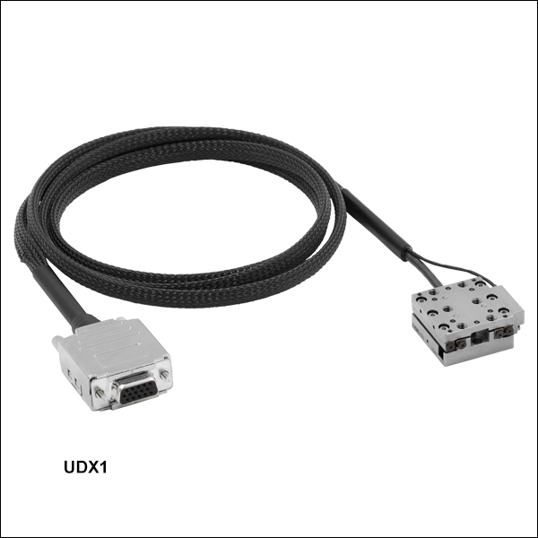
UDX1
Ultrasonic Piezo Stage
with Optical Encoder,
20 mm Travel
UDXC
Ultrasonic Piezo Stage Controller


Please Wait
| ORIC® Piezo Stage Selection Guide |
|---|
| 4.5 mm Piezo Inertia Vertical Translation Stage |
| 5 mm Piezo Inertia Linear Translation Stages |
| 12 mm Piezo Inertia Linear Translation Stages |
| 20 mm Piezo Inertia Linear Translation Stages |
| 20 mm Ultrasonic Piezo Linear Translation Stages |
| 50 mm Piezo Inertia Linear Translation Stages |
| Piezo Inertia Rotation Stages |
| Piezo Inertia Vacuum-Compatible Stages |
| Quick Links |
|---|
| Linear Stage with Optical Encoder |
| Adapters |
| Controller |
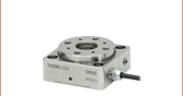
Click to Enlarge
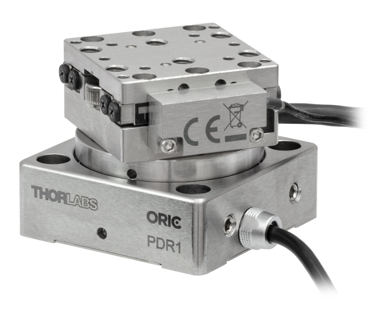
Figure 1.1 Translation + rotation stage created by mounting a UDX1 linear stage on a PDR1 rotation stage using the included dowel pins and mounting hardware.

Features
- Compact 20 mm Travel Stainless Steel Stage with Ultrasonic Piezo Drive
- Ideal for OEMs and Set-and-Hold Applications that Require Relative Positioning with High Speed (Up to 100 mm/s) and Force
- Top Plate Adapters Provide Alternative Mounting Hole Patterns
- Mounting Adapters Provide Flat Surfaces for Mounting Stages
- Right-Angle Bracket Adapter Allows Vertical Mounting and XYZ Configurations
- Requires an Ultrasonic Piezo Stage Controller (Sold Separately Below)
Thorlabs' ORIC® 20 mm Linear Travel Ultrasonic Piezoelectric Drive Stage provides fast and stable piezo-controlled linear motion in a compact, 15.0 mm thick package with no backlash. The UDX1(/M) single-axis stage features an optical encoder and supports closed-loop operation. The ultrasonic piezo drive mechanism of these stages is self-locking when the stage is at rest and no power is supplied to the piezo, making the stage ideal for set-and-hold applications that require nanometer resolution and long-term alignment stability. The resonant ultrasonic mechanism makes this stage ideal for applications requiring high speed and force, operating at typical speeds up to 100 mm/s while using less energy than our piezo inertia stages.
Load Mounting Options
The load can be secured to the stage's moving platform using 2-56 (M2 x 0.4) threaded holes or 8-32 (M4 x 0.7) threaded holes. Alternatively, the PD1T(/M) and PD1U(/M) adapter plates (sold separately below) provide alternative mounting hole patterns for the top plate of the stage. The load can be aligned using the array of Ø2 mm, 1.5 mm deep dowel pin holes; see the drawings below for details. Thorlabs offers replacement dowel pins in packs of 20 below. Ensure that the maximum insertion depth of these holes is not exceeded or else the stage may be damaged. For more information, please refer to the Specs tab or the support documents accessible through the red Support Docs icons ![]() )
)
Stage Mounting Options
Counterbores for mounting each stage are accessible when the moving plate is translated to the ends of the travel range. There are two mounting options: two 2-56 (M2 x 0.4) screws on the corners with 0.35 N·m recommended torque or 8-32 (M4 x 0.7) screws along opposing edges of the base with 0.55 N·m recommended torque.
The stages should be mounted on an even surface with a recommended flatness of ≤5 μm. If the stage is mounted on a surface with >5 µm flatness (as with most breadboards and optical tables), the mounting torque may need to be decreased in order for the velocity variation and pitch/yaw of the stage to meet specifications. If needed, the PD1B(/M), PD1B2(/M), and PD1B3(/M) mounting adapters provide a mounting surface with precise flatness to avoid warping the stage when mounting it to a table surface.
Two linear stages can be stacked on top of each other for an XY configuration for applications that require additional movement. The top and bottom of each stage feature four Ø2 mm holes for alignment via the included dowel pins, providing XY translation with orthogonality <5 mrad.
The PD1Z(/M) right-angle bracket adapter allows one single-axis stage to be mounted vertically on top of another stage for an XZ or XYZ configuration. Alternatively, the bracket and single-axis stage can be used with a PD1B(/M), PD1B2(/M) or PD3B(/M) adapter for a Z-configuration that can be directly mounted to an optical table or breadboard. Note that when the stage is mounted vertically, the load capacity is greatly reduced. Please see the Specs tab for more details.
Compatibility with Other ORIC Stages
These stages can be combined with an ORIC rotation stage for applications that require XY translation and rotation, an example of which is shown to the above and to the right. An XZ or XYZ configuration can be created by mounting one or more ORIC 20 mm linear stages onto the top platform of a PDXZ1(/M) piezo inertia stage with 4.5 mm of vertical motion. ORIC 20 mm linear stages can also be mounted on one of our ORIC 50 mm linear stages where greater travel range is necessary.
Required Controller
Our UDXC ultrasonic piezo controller is required to operate these stages. Note that the ultrasonic piezo drives cannot be driven using a standard piezo or piezo inertia controller. Please see below for more information on the UDXC controller.
Click to Enlarge
Figure 1.3 Simplified Illustration Showing the Operation of the Ultrasonic Piezo Drive

Figure 1.4 The ultrasonic drive cycle consists of an oscillation in the deformation of the piezo element.
Ultrasonic Piezoelectric Motor
The ultrasonic piezo drive motor primarily consists of three main parts: a piezo motor, a friction component, and a slider (carriage plate). At point (A) shown in Figure 1.3 and the corresponding plot in Figure 1.4, the piezo motor is at the home position. One end of the motor is elastically fixed and the opposite end is in contact with the friction component. When the selected section of the motor is driven at its resonance, the non-fixed end traces an elliptical path in space. Point (B) shows the motor at the peak of its deformation; the motor has deformed to drive the friction component and slider during the upper half of the elliptical path. At point (C), the motor and friction component return to their home positions along the lower half of the elliptical path. The friction component will effectively detach from the slider so that the slider can retain its translated position. Figure 1.4 shows the deformation amplitude of the motor as a function of time through a cycle from (A) to (B) to (C).
With the resonant driving and the inertia of the slider, the slider will move forward slightly after each elliptical cycle. Repeated cycles will drive the slider forward. For backwards travel, the opposite section of the piezo motor is driven, deforming conversely such that it traces an ellipse in the opposite direction. Resonant vibration cycles result in high translation speed and force while driving at an ultrasonic frequency makes it low noise.
Due to a number of factors that include the application conditions, piezo hysteresis, component variance, and the axial load, the achieved step size will vary and is not repeatable. To help overcome this variance, an optical encoder provides external feedback to ensure repeatable motion.
| Table 2.1 UDX1(/M) Specificationsa,b | |||
|---|---|---|---|
| Stage Type | Single-Axis Stage with Closed-Loop Ultrasonic Piezo Drive | ||
| Travel | 20.0 mm | ||
| Optical Encoder Resolution | 12.5 nm | ||
| Bidirectional Repeatability | ±0.75 µm | ||
| Absolute Accuracy | ±2 µm | ||
| Minimum Incremental Motionc | 500 nm | ||
| Step Size Adjustabilityd | 10 nm to 10.00 mm | ||
| Settling Time (Typical) | 300 ms | ||
| Drive Frequency | 200 kHz | ||
| Speed (Typical Max, Continuous Stepping)c,e | 100 mm/s | ||
| Horizontal Load Capacity | 3 kg (6.6 lbs) | ||
| Vertical Load Capacityf | 150 g (5.3 oz) | ||
| Clamping / Holding Force | 4 N | ||
| Pitch / Yaw Deviation Over Travel Range | ≤200 µrad | ||
| XY Stacked Orthogonality | <5 mrad | ||
| Motor Type | Ultrasonic Piezoelectric Drive | ||
| Lifetimeg | ≥100 km | ||
| Piezo Specifications | |||
| Max Operating Voltage | 30 V | ||
| Capacitance | 90 nF | ||
| Physical Specifications | |||
| Operating Temperature | 10 to 40 °C | ||
| Connector Type | D-Sub 15-Pin Female | ||
| Cable Lengthh | 1.5 m (4.9 ft) | ||
| Top Plate Mounting Options |
Four 2-56 (M2 x 0.4) Threaded Holes, 3.5 mm Deep Six 8-32 (M4 x 0.7) Threaded Holes, 3.2 mm Deep Six Ø2 mm Dowel Pin Holes, 1.5 mm Deep PD1T(/M) and PD1U(/M) Adapters |
||
| Dimensions | 36.7 mm x 32.5 mm x 15.0 mm (1.44" x 1.28" x 0.59") |
||
| Weight (Including Cable) | 160 g (5.64 oz) | ||
| Required Controller (Sold Separately Below) |
UDXC | ||
| Table 2.2 UDXC Specificationsa | |||
|---|---|---|---|
| D-Sub Port | Number of Ports | One | |
| Voltage | 0 to 30 V | ||
| Frequency | 220 kHz Max | ||
| Max Current Limit | 8 A | ||
| Front USB | Type A, USB HID Host | ||
| Back USB | Type B, USB Device 2.0 | ||
| I/O Port | Voltage of Analog In/Out | -10 to 10 V, ±2% | |
| Voltage of Trigger In/Out | 0 to 5 V, TTL | ||
| Ethernet PC Communication | One RJ-45 Port | ||
| Dimensions (L x W x H) | 115.2 mm x 150.0 mm x 48.5 mm (4.54” x 5.91” x 1.91”) |
||
| Weight | 0.33 kg | ||
| Operating Temperature | 10 - 35 °C | ||
| DS12 Input Power | 100 - 240 VAC, 50 - 60 Hz | ||
| Input Power | 12 VDC, 3 A | ||
| Compatible Stages | UDX1(/M) | ||
UDX1(/M) Stage
Female 15-Pin D-Sub
| Pin(s) | Voltage Range | Name | Description |
|---|---|---|---|
| 1 | -7.5 to +12.5 V | Encoder_B_N | Encoder B- |
| 2 | -7.5 to +12.5 V | Encoder_B_P | Encoder B+ |
| 3 | 0 V | GND | Digital Ground |
| 4 | -7.5 to +12.5 V | Encoder_A_N | Encoder A- |
| 5 | -7.5 to +12.5 V | Encoder_A_P | Encoder A+ |
| 6 | - | - | Reserved |
| 7 | - | - | Reserved |
| 8 | +5 V | +5 V | 5 V Power |
| 9 | -7.5 to +12.5 V | Encoder_Z_N | Encoder Z- |
| 10 | -7.5 to +12.5 V | Encoder_Z_P | Encoder Z+ |
| 11 | 0 to +30 V | SigOut2 | Piezo Output 2 |
| 12 | 0 V | PGND | Power Ground |
| 13 | 0 to +30 V | SigOut1 | Piezo Output 1 |
| 14 | 5 V TTL | EEPROM | 1-Wire EEPROM |
| 15 | - | - | Reserved |
UDXC Front Panel
Male 15-Pin D-Sub
For UDX1(/M) Stages
For closed-loop operation, with a resolution down to 12.5 nm and speed up to 200 mm/s.
| Pin(s) | Voltage Range | Name | Description |
|---|---|---|---|
| 1 | -7.5 to +12.5 V | Encoder_B_N | Encoder B- |
| 2 | -7.5 to +12.5 V | Encoder_B_P | Encoder B+ |
| 3 | 0 V | GND | Digital Ground |
| 4 | -7.5 to +12.5 V | Encoder_A_N | Encoder A- |
| 5 | -7.5 to +12.5 V | Encoder_A_P | Encoder A+ |
| 6 | - | - | Reserved |
| 7 | - | - | Reserved |
| 8 | +5 V | +5 V | 5 V Power |
| 9 | -7.5 to +12.5 V | Encoder_Z_N | Encoder Z- |
| 10 | -7.5 to +12.5 V | Encoder_Z_P | Encoder Z+ |
| 11 | 0 to +30 V | SigOut2 | Piezo Output 2 |
| 12 | 0 V | PGND | Power Ground |
| 13 | 0 to +30 V | SigOut1 | Piezo Output 1 |
| 14 | 5 V TTL | EEPROM | 1-Wire EEPROM |
| 15 | - | - | Reserved |
I/O Port
An I/O cable is provided to breakout the Trigger In, Trigger Out, Analog In, and Analog Out pins to BNCs on included cable.
| Pin | Voltage Range | Name | Description |
|---|---|---|---|
| 1 | - | - | Reserved |
| 2 | 0 V | GND | Ground Pin |
| 3 | 0 to 5 V | Trigger In | Trigger to Update New Target Position |
| 4 | 0 V | GND | Ground Pin |
| 5 | -10 to +10 V | Analog In | Input as New Target Position |
| 6 | - | - | Reserved |
| 7 | 0 V | GND | Ground Pin |
| 8 | 0 to 5 V | Trigger Out | Trigger When Actual Position is on Target |
| 9 | -10 to +10 V | Analog Out | Output to Reflect the Actual Position |
RS-232
Connects to a computer for command-line control.
| Pin(s) | Voltage Range | Name | Description |
|---|---|---|---|
| 1 | - | N.C. | Not Connected |
| 2 | -15 to +15 V | TXD | Transmits Data |
| 3 | -15 to +15 V | RXD | Receives Data |
| 4 | - | N.C. | Not Connected |
| 5 | 0 V | GND | Ground Pin |
| 6,7,8,9 | - | N.C. | Not Connected |
USB (Type A)

Connects an HID MCMK3 joystick (available separately below) to control the stage movement by scrolling the wheel back and forth. When the device is set in open-loop operation, it will move a set number of pulses with each scroll, while in closed-loop operation it will move at a set step distance with each scroll.
UDXC Back Panel

RJ-45 Port
Connects the UDXC device to a router/switch for software control with a networked PC.
USB (Type B)

The USB port connects to a computer for software or command-line control.
ソフトウェア
Kinesisバージョン1.14.53
このKinesisソフトウェアパッケージには、当社のKinesisシステムコントローラを制御するためのGUIが含まれています。
下記もご用意しております。
- 通信プロトコル

Figure 58A KinesisソフトウェアのGUI画面
当社のKinesisソフトウェアパッケージを用いて、当社の様々なモーションコントローラを駆動することができます。このソフトウェアは小型で低出力のシングルチャンネルドライバ(K-Cube®など)から、高出力でマルチチャンネルのベンチトップ型ユニットやモジュール型の19インチラックナノポジショニングシステム(ラックシステムMMR60x)まで、当社Kinesisシリーズの様々なモーションコントローラの制御用にご使用いただけます。
Kinesisソフトウェアでは.NETコントロールを使用できるため、最新のC#、Visual Basic、LabVIEW™、あるいはその他の.NET対応言語を使用してカスタムプログラムを作成することができます。.NETフレームワークやAPIの使用を想定していないアプリケーションのために、ローレベルのDLLライブラリも含まれています。中央シーケンスマネージャ(Central Sequence Manager)は、当社のすべてのモーションコントロール用ハードウェアの統合と同期の機能をサポートしています。
この共通のソフトウェアプラットフォームにより、ユーザは単一のソフトウェアツールを習得するだけで、あらゆるモーションコントロールデバイスを1つのアプリケーション内で組み合わせて使用することができます。このように1軸システム用から多軸システム用までのあらゆるコントローラを組み合わせ、それら全てを1台のPCの統合されたソフトウェアインターフェイスから制御できます。
このソフトウェアパッケージには2つの使い方があります。1つはGUI(グラフィカルユーザーインターフェイス)ユーティリティを用いる方法で、コントローラの到着後すぐに直接的な操作と制御を行なうことができます。もう1つは一連のプログラミングインターフェイスを用いる方法で、ご希望の開発言語によりカスタム仕様の位置決めやアライメント用のプログラムを簡単に作成することができます。
Kinesisソフトウェアでは新しい.NETコントロールが使用でき、最新の最新のC#, Visual Basic, LabVIEW™、ほかの.NET対応言語を使用する開発者がカスタムにプログラムを作成することもできます。
C#
このプログラミング言語はマルチプログラミングパラダイムやマルチプログラミング言語が使用可能となるよう設計されているため、複雑な問題が簡単かつ効率的に解決できます。型付け、命令型、宣言型、関数型、ジェネリック、オブジェクト指向、そしてコンポーネント指向が含まれます。 この共通のソフトウェアプラットフォームにより、1セットのソフトウェアツールを習得するだけで、あらゆるKinesisコントローラを簡単に組み合わせることができます。このようにして1軸システムのコントローラから多軸システムのコントローラまで、様々なコントローラを組み合わせ、全てを1台のPCのソフトウェアインターフェイスから制御することが可能となりました。
Kinesisシステムソフトウェアを使用するには2つの手段があります。コントローラを直接つないで制御を行なう付属のGUI(グラフィカルユーザーインターフェイス)ユーティリティ、またはご希望の開発言語でカスタム仕様の位置決めやアライメントを簡単にプログラムできる一連のプログラミングインターフェイスです。
Kinesisモーションコントロールライブラリの構築の参考となる実行可能なプロジェクト機能拡張例については下のリンクをクリックしてください。なお、Quick Startのプロジェクト例の実行には別の統合開発環境(IDE)(Microsoft Visual Studioなど)が必要です。C#のプロジェクト例はKinesisソフトウェアパッケージに付属する.NETコントロールで実行可能です(詳細は「Kinesisソフトウェア」タブをご覧ください)。
 | Click Here for the Kinesis with C# Quick Start Guide Click Here for C# Example Projects Click Here for Quick Start Device Control Examples | |
LabVIEW
LabVIEWは、.Netコントロールを介してKinesisベースのコントローラとの通信に使用できます。LabVIEWでは、ツールとオブジェクトでフロントパネルとして知られるユーザーインターフェイスを構築した後、グラフィカル表記の関数を使ってコードを追加し、フロントパネルのオブジェクトを制御します。下記のLabVIEWチュートリアルでは.Netコントロールを使用してLabVIEW内Kinesis駆動デバイス用の制御GUIを作成するための情報をご提供しています。 LabVIEWでコントローラを制御する基本的な方法や、LabVIEW GUIを用いてデバイスを操作する前に行うべき設定の手順についても解説しています。
 | Click Here to View the LabVIEW Guide Click Here to View the Kinesis with LabVIEW Overview Page | |
| Posted Comments: | |
| No Comments Posted |
電動リニアステージ
電動の直線移動ステージとしては、ピエゾ駆動の20 µm移動ステージからダイレクトドライブ方式の600 mm移動ステージまで、様々な最大移動量の製品をご用意しております。ステージの多くは、それらを用いてXY軸やXYZ軸などの多軸ステージを構築することができます。ファイバ結合用としては、多軸ステージのページをご覧ください。標準の電動ステージを用いるよりも精密な調整が可能です。直線移動ステージのほかに、電動の回転ステージおよびゴニオステージもご用意しております。また手動移動ステージもございます。
ピエゾステージ
これらのステージでは、様々な駆動機構にピエゾ素子が組み込まれています。ステージORIC®シリーズでは、「スティック-スリップ」と呼ばれる摩擦特性を利用したピエゾ慣性アクチュエータが用いられており、それにより長い移動距離が得られています。移動ステージNanoflex™シリーズは、手動アクチュエータに加えて標準的なピエゾアクチュエータが用いられています。ステージElliptec®シリーズでは共振ピエゾモータが用いられており、共振に伴うモータ先端の楕円形の動きで可動プラットフォームを押したり引いたりします。Z軸ステージLPS710E/Mにはピエゾ移動に対する機械的な増幅機構が組み込まれており、またそれに適したコントローラが付属しています。
| Piezoelectric Stages | ||||
|---|---|---|---|---|
| Product Family | ORIC® PDXZ1 Closed-Loop 4.5 mm Vertical Stage | ORIC® PD2 Open-Loop 5 mm Stage | ORIC® PDX2 Closed-Loop 5 mm Stage | ORIC® PDX4 Closed-Loop 12 mm Stage |
| Click Photo to Enlarge | 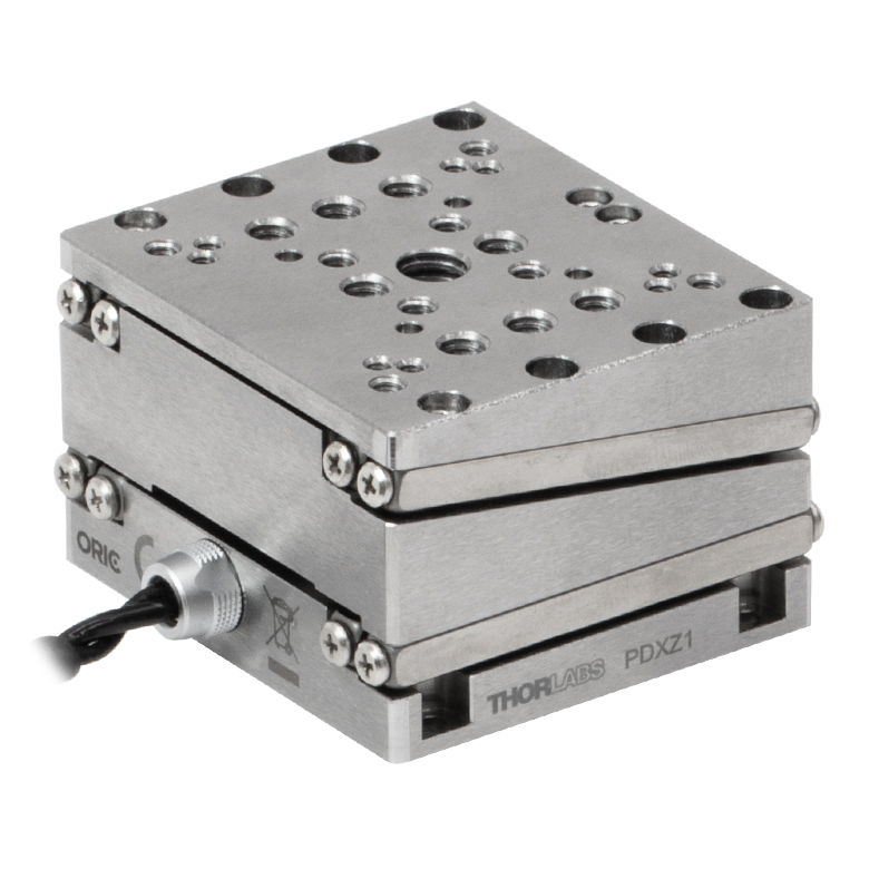 |  |  | 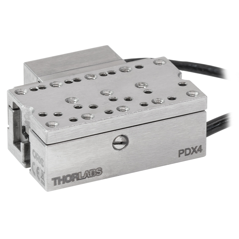 |
| Travel | 4.5 mm | 5 mm | 12 mm | |
| Speed | 1 mm/s (Typ.)a | 10 mm/s (Typ. Max)b | 8 mm/s (Typ.)c | 15 mm/s (Typ.)a,c |
| Drive Type | Piezoelectric Inertia Drive | |||
| Possible Axis Configurations | Z | X, XY, XYZ | ||
| Mounting Surface Size | 45.0 mm x 42.0 mm | 13.0 mm x 13.0 mm | 13.0 mm x 23.0 mm | |
| Additional Details | ||||
| Piezoelectric Stages | |||||||
|---|---|---|---|---|---|---|---|
| Product Family | ORIC® PD1 Open-Loop 20 mm Stage | ORIC® PD1D Open-Loop 20 mm Monolithic XY Stage | ORIC® PDX1 Closed-Loop 20 mm Stage | ORIC® PDX1A Closed-Loop 20 mm Stage Low-Profile | ORIC® PD3 Open-Loop 50 mm Stage | ORIC® PDX3 Closed-Loop 50 mm Stage | |
| Click Photo to Enlarge | 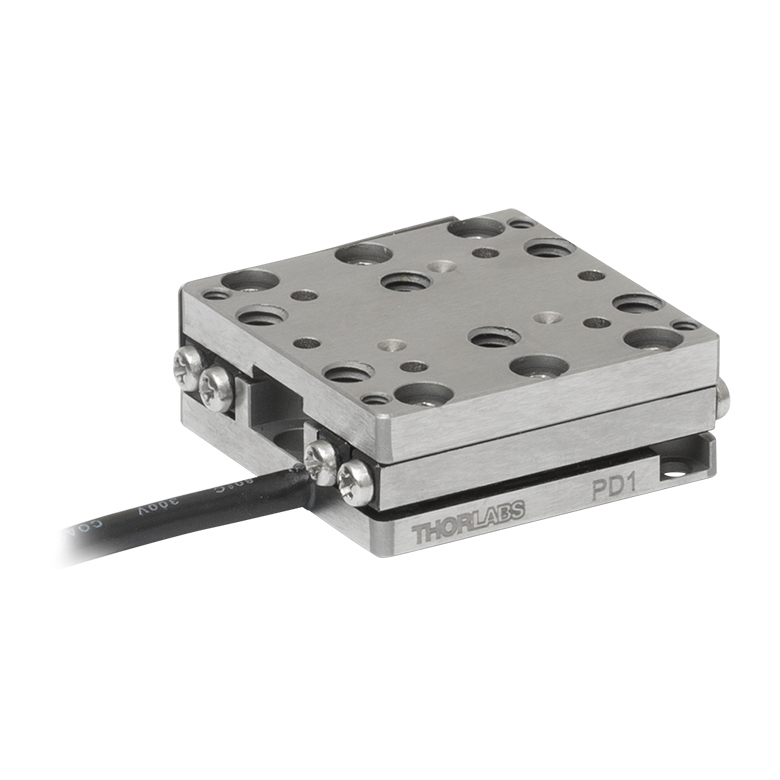 | 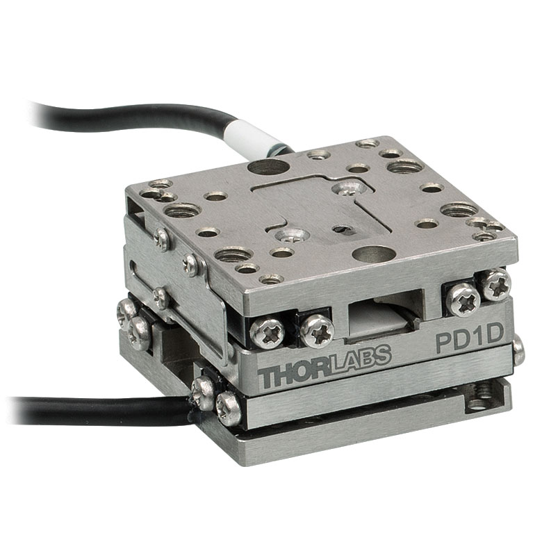 | 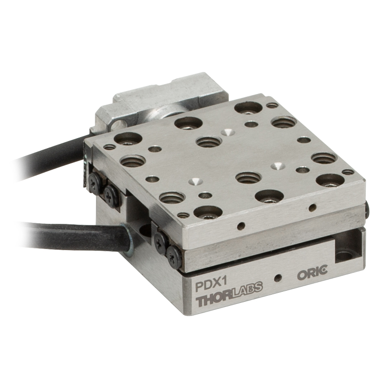 | 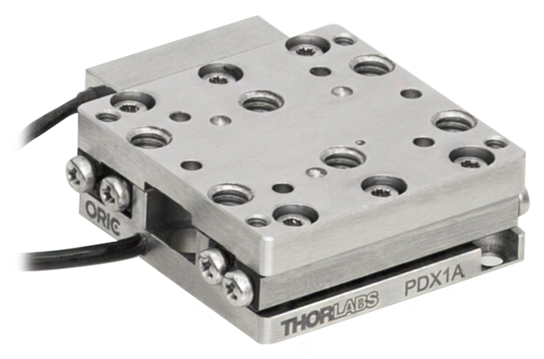 |  |  | |
| Travel | 20 mm | 50 mm | |||||
| Speed | 3 mm/s (Typ. Max)a | 20 mm/s (Typ. Max)c | 10 mm/s (Typ.)b | 10 mm/sd | 10 mm/s (Typ. Max)b | ||
| Drive Type | Piezoelectric Inertia Drive | ||||||
| Possible Axis Configurations | X, XY, XYZ | XY, XYZ | X, XY, XYZ | X, XY, XYZ | X, XY, XYZ | X, XY, XYZ | |
| Mounting Surface Size | 30 mm x 30 mm | 80 mm x 30 mm | |||||
| Additional Details | |||||||
| Piezoelectric Stages | |||||||
|---|---|---|---|---|---|---|---|
| Product Family | Nanoflex™ 20 µm Stage with 5 mm Actuator | Nanoflex™ 25 µm Stage with 1.5 mm Actuator | Compact Modular XRN25X 25 mm Stage | Modular XR25X 25 mm Stage | Elliptec® 28 mm Stage | Elliptec® 60 mm Stage | LPS710E 1.1 mm Vertical Stage |
| Click Photo to Enlarge | 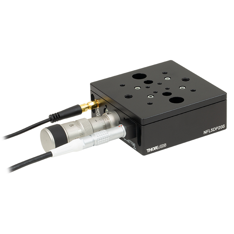 | 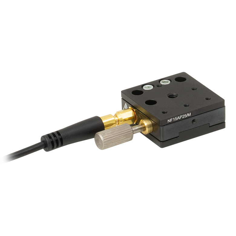 |  |  | 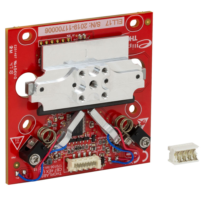 | 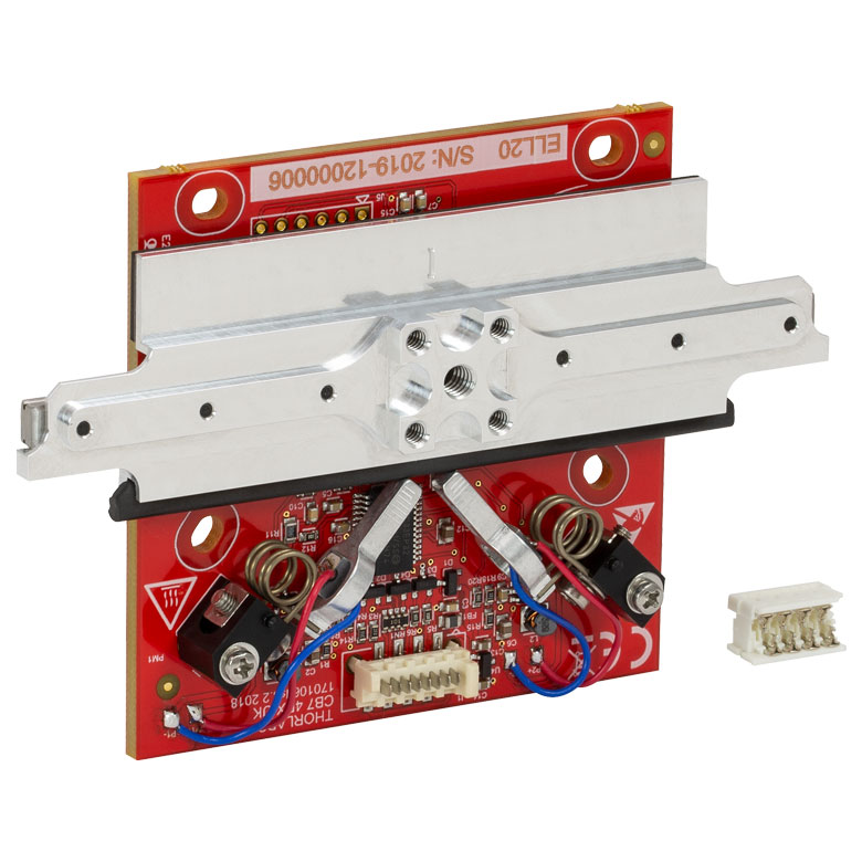 | 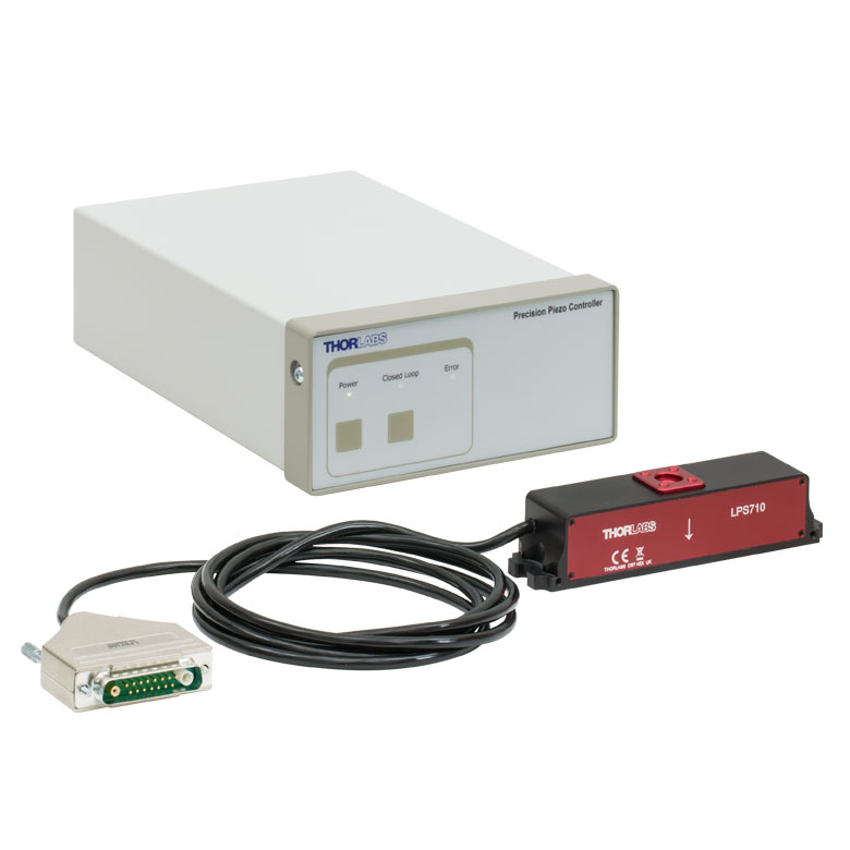 |
| Travel | 20 µm + 5 mm Manual | 25 µm + 1.5 mm Manual | 25 mm | 28 mm | 60.0 mm | 1.1 mm | |
| Maximum Velocity | - | ≤3.6 mm/mina | 180 mm/s | 90 mm/s | - | ||
| Drive Type | Piezo with Manual Actuator | Piezoelectric Inertia Drive | Resonant Piezoelectric Motor | Amplified Piezo | |||
| Possible Axis Configurations | X, XY, XYZ | X, XY, YZ, XZ, XYZ | X | Z | |||
| Mounting Surface Size | 75 mm x 75 mm | 30 mm x 30 mm | 85.0 mm x 50.7 mm | 110.0 mm x 75.7 mm | 15 mm x 15 mm | 21 mm x 21 mm | |
| Additional Details | |||||||
ステッピングモーターステージ
こちらの移動ステージは脱着型あるいは内蔵型のステッピングモータを用いており、また300 mmまでの長い移動量が可能です。これらのステージの多くは多軸移動機能を有していたり(PLSXY)、あるいは多軸ステージを組み立てることが可能であったりします(PLSX、クイック接続型XR25シリーズ、LNRシリーズ、NRTシリーズ、LTSシリーズ)。ステージMLJ150/Mは高荷重にも対応する垂直移動ステージです。
| Stepper Motor Stages | |||||
|---|---|---|---|---|---|
| Product Family | PLSX with and without PLST(/M) Top Plate 1" Stage | PLSXY with and without PLST(/M) Top Plate 1" Stage | LNR Series 25 mm Stage | LNR Series 50 mm Stage | |
| Click Photo to Enlarge | 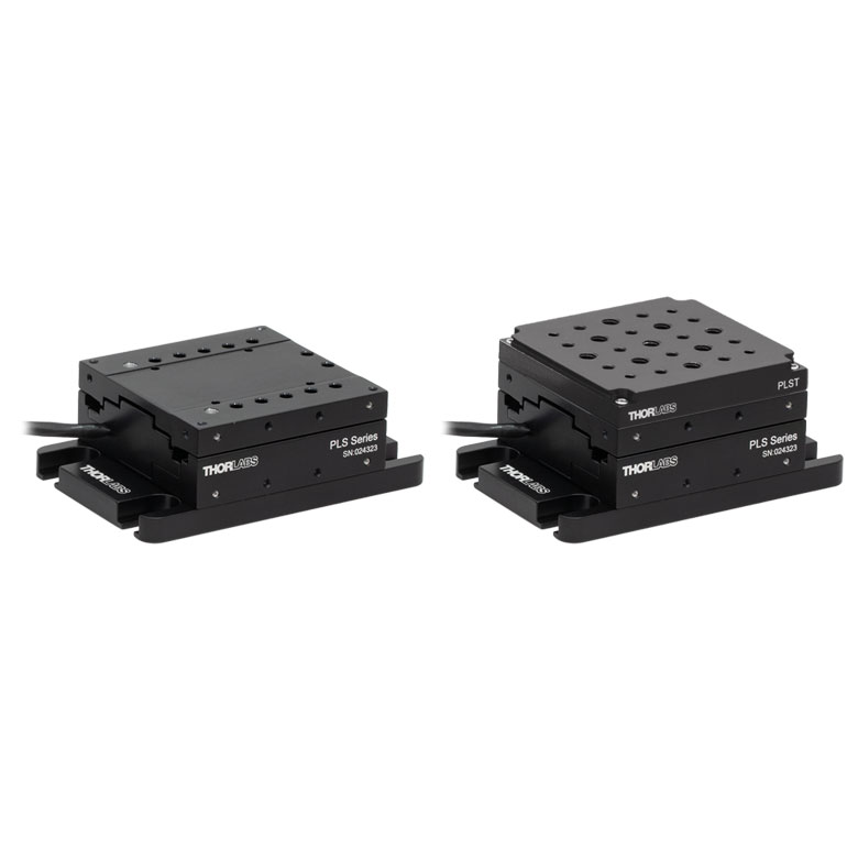 | 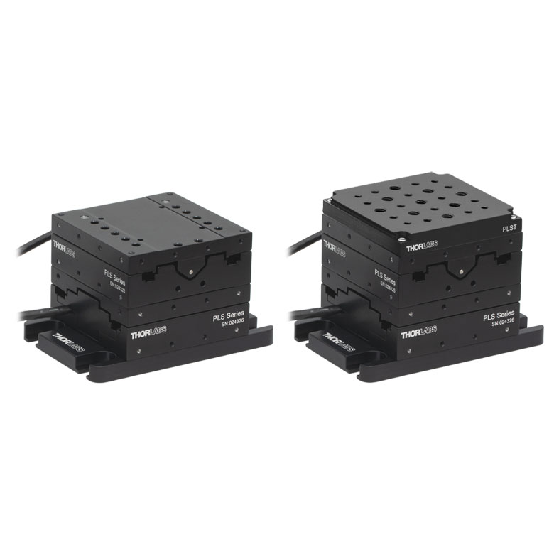 | 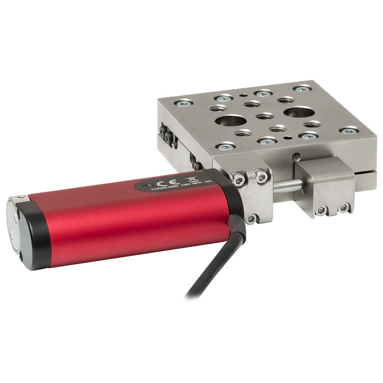 | 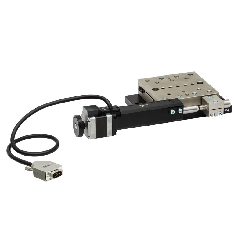 | |
| Travel | 1" | 25 mm | 50 mm | ||
| Maximum Velocity | 7.0 mm/s | 2.0 mm/s | 50 mm/s | ||
| Possible Axis Configurations | X, XY | X, XY, XYZ | X, XY, XYZ | ||
| Mounting Surface Size | 3" x 3" | 60 mm x 60 mm | 100 mm x 100 mm | ||
| Additional Details | |||||
| Stepper Motor Stages | ||||||
|---|---|---|---|---|---|---|
| Product Family | NRT Series 100 mm Stage | NRT Series 150 mm Stage | LTS Series 150 mm Stage | LTS Series 300 mm Stage | MLJ250 50 mm Vertical Stage | |
| Click Photo to Enlarge |  | 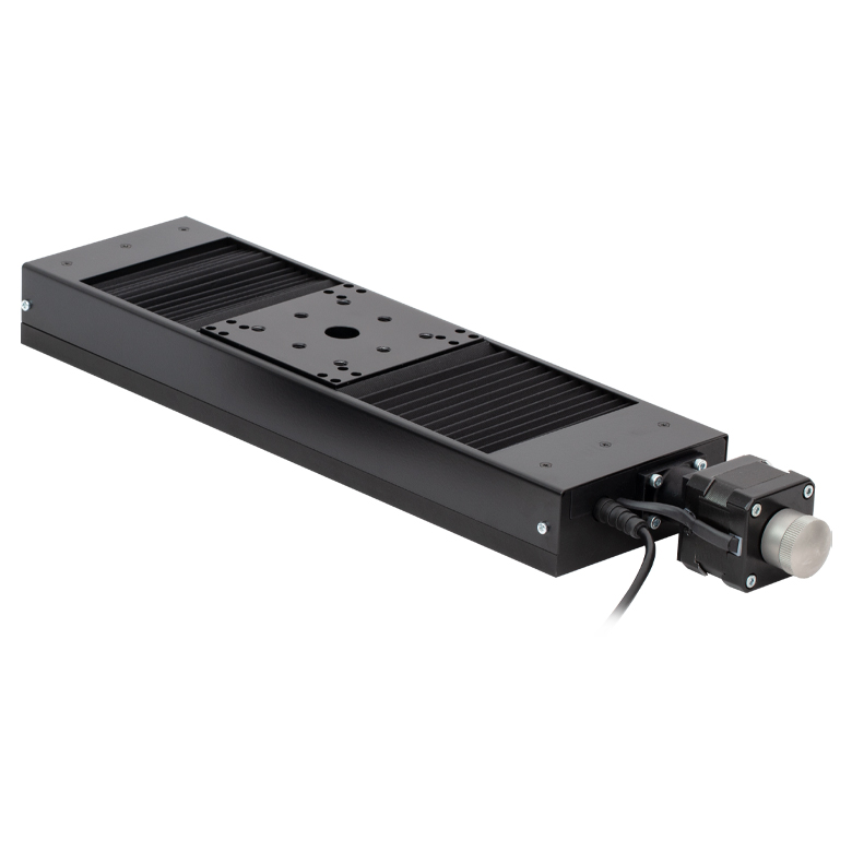 | 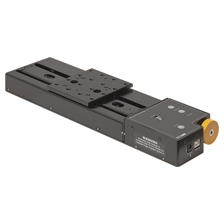 |  | 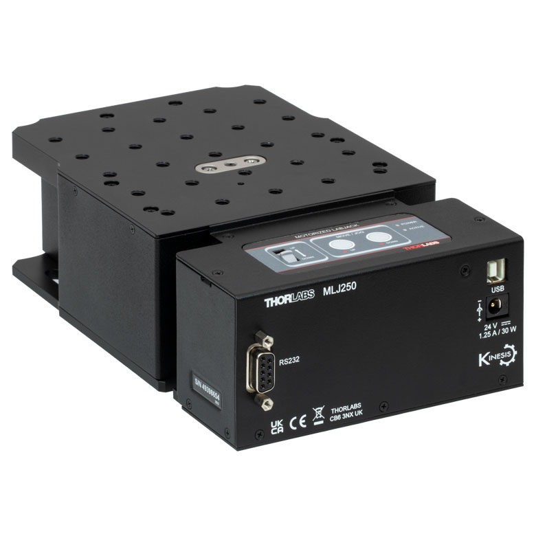 | |
| Travel | 100 mm | 150 mm | 150 mm | 300 mm | 50 mm | |
| Maximum Velocity | 30 mm/s | 50 mm/s | 3.0 mm/s | |||
| Possible Axis Configurations | X, XY, XYZ | X, XY, XYZ | Z | |||
| Mounting Surface Size | 84 mm x 84 mm | 100 mm x 90 mm | 148 mm x 131 mm | |||
| Additional Details | ||||||
DCサーボモーターステージ
脱着型あるいは内蔵型のDCサーボモータを用いた直線移動ステージをご用意しております。これらのステージは薄型で、多軸ステージの構築が可能です。
| DC Servo Motor Stages | ||||
|---|---|---|---|---|
| Product Family | MT Series 12 mm Stages | PT Series 25 mm Stages | MTS Series 25 mm Stage | MTS Series 50 mm Stage |
| Click Photo to Enlarge |  | 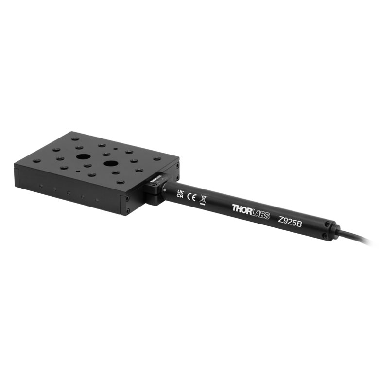 | 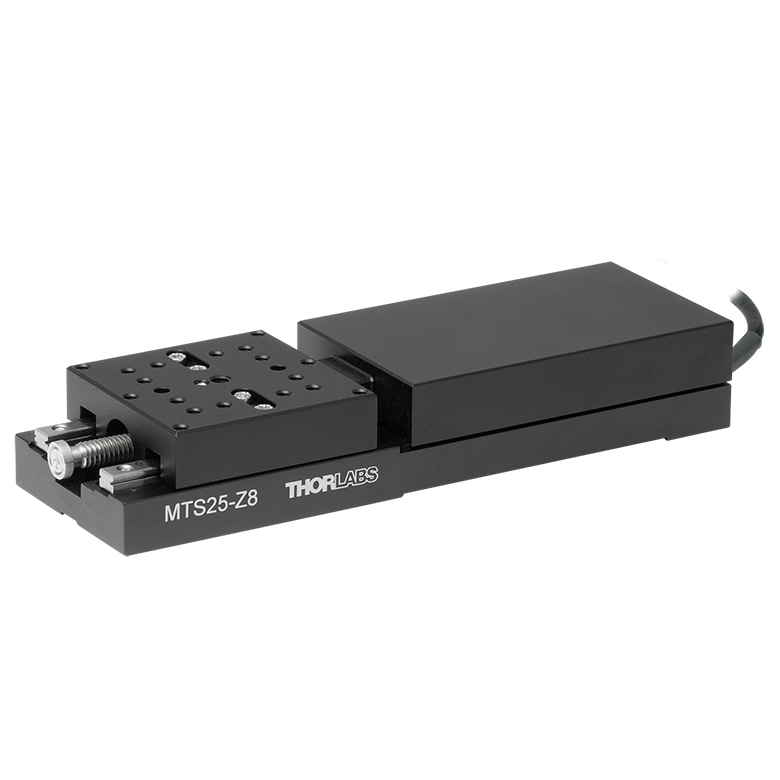 | 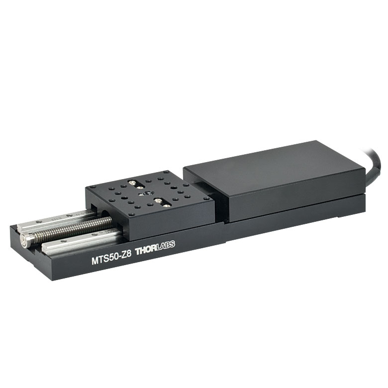 |
| Travel | 12 mm | 25 mm | 25 mm | 50 mm |
| Maximum Velocity | 2.6 mm/s | 2.4 mm/s | ||
| Possible Axis Configurations | X, XY, XYZ | X, XY, XYZ | ||
| Mounting Surface Size | 61 mm x 61 mm | 101.6 mm x 76.2 mm | 43 mm x 43 mm | |
| Additional Details | ||||
| DC Servo Motor Stages | ||||
|---|---|---|---|---|
| Product Family | M30 Series 30 mm Stage | M30 Series 30 mm Monolithic XY Stage | M150 Series 150 mm XY Stage | KVS30 30 mm Vertical Stage |
| Click Photo to Enlarge |  | 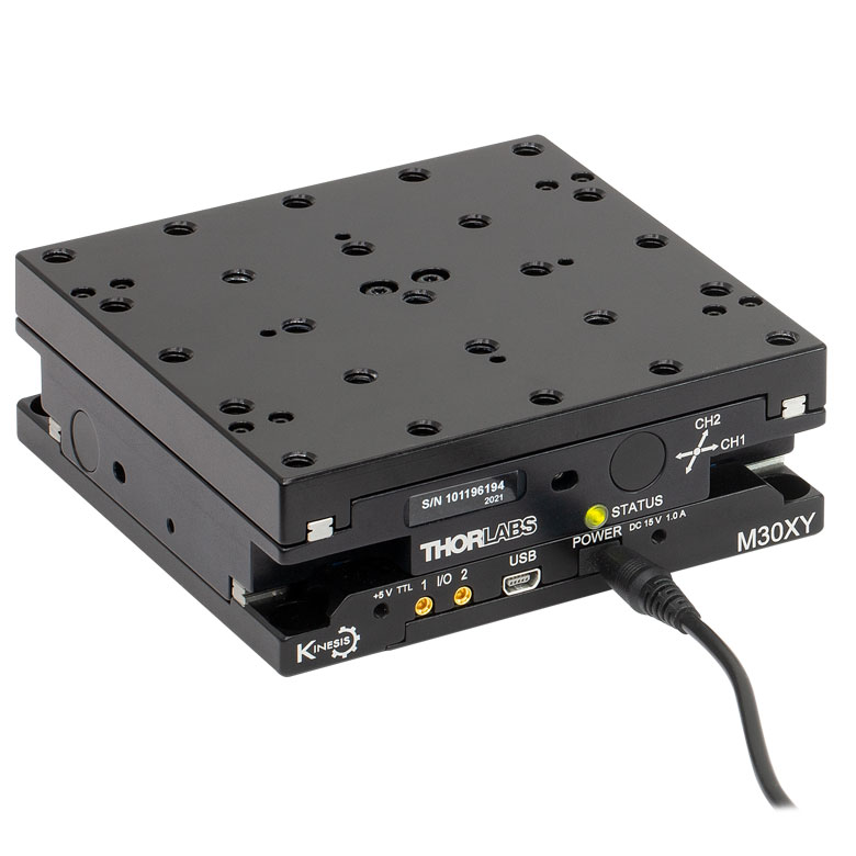 | 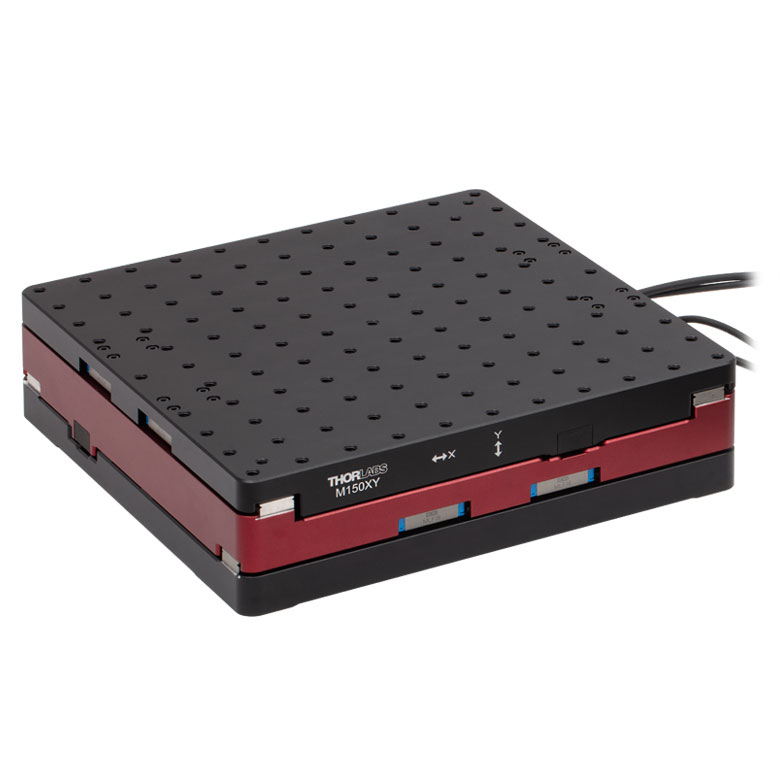 | 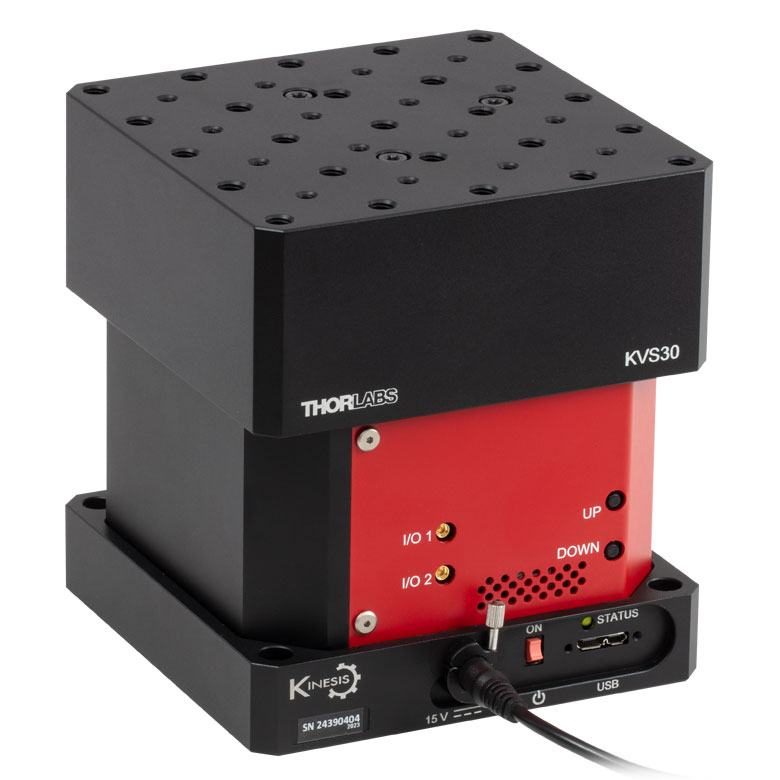 |
| Travel | 30 mm | 150 mm | 30 mm | |
| Maximum Velocity | 2.4 mm/s | X-Axis: 170 mm/s Y-Axis: 230 mm/s | 8.0 mm/s | |
| Possible Axis Configurations | X, Z | XY, XZ | XY | Z |
| Mounting Surface Size | 115 mm x 115 mm | 272.4 mm x 272.4 mm | 116.2 mm x 116.2 mm | |
| Additional Details | ||||
ダイレクトドライブステージ
こちらの薄型ステージにはブラシレスDCサーボモータが内蔵されており、バックラッシュの無い高速移動が可能です。電源が入ってないときは、ステージのプラットフォームにはほとんど慣性が無く、実質的にフリーラン状態になります。そのため電源が入ってないときにステージのプラットフォームが定位置に留まる必要のある用途には適していません。これらのステージを垂直方向に取付けることは推奨しません。
| Direct Drive Stages | |||||
|---|---|---|---|---|---|
| Product Family | DDS Series 50 mm Stage | DDS Series 100 mm Stage | DDS Series 220 mm Stage | DDS Series 300 mm Stage | DDS Series 600 mm Stage |
| Click Photo to Enlarge | 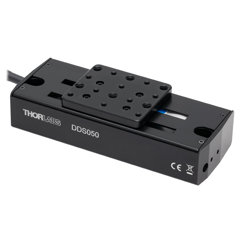 | 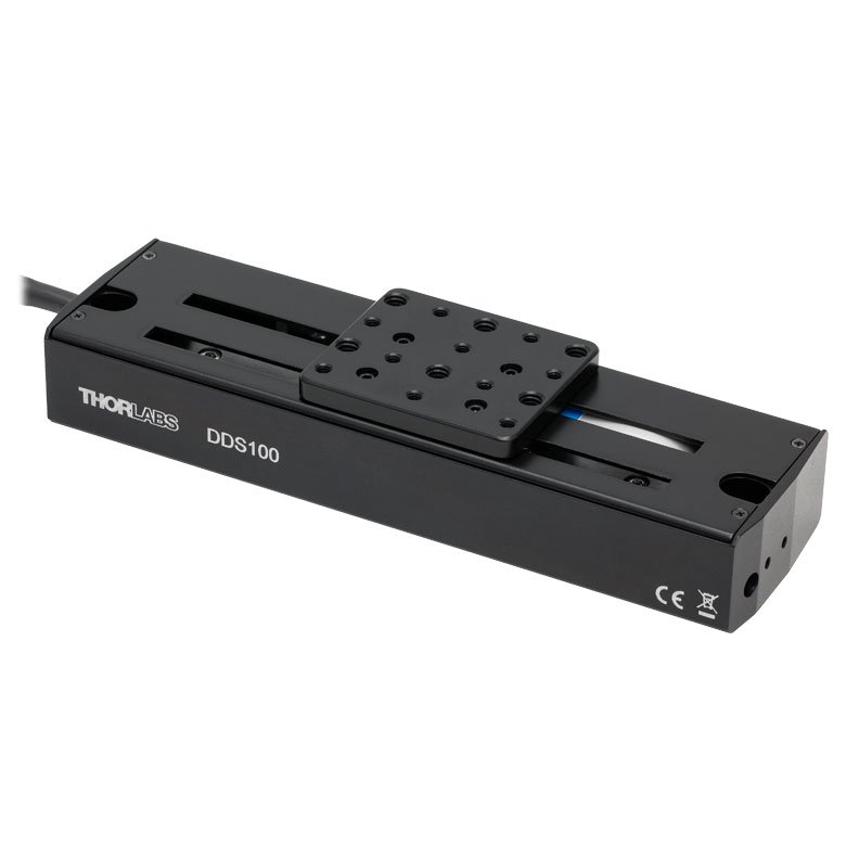 | 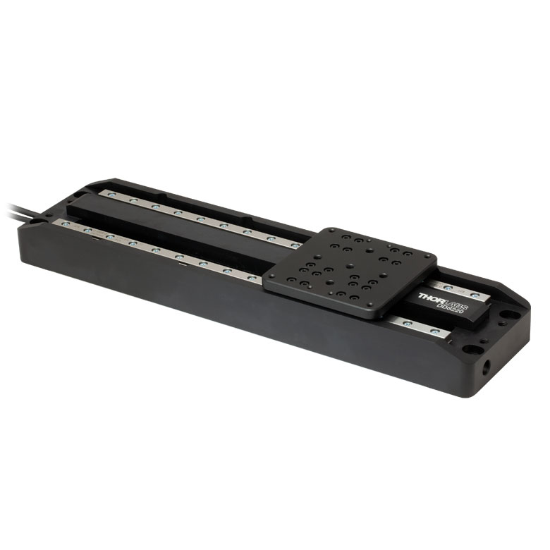 | 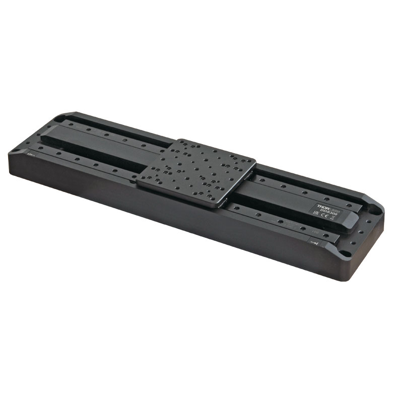 |  |
| Travel | 50 mm | 100 mm | 220 mm | 300 mm | 600 mm |
| Maximum Velocity | 500 mm/s | 300 mm/s | 400 mm/s | 400 mm/s | |
| Possible Axis Configurations | X, XY | X, XY | X | X | |
| Mounting Surface Size | 60 mm x 52 mm | 88 mm x 88 mm | 120 mm x 120 mm | ||
| Additional Details | |||||

 ズーム
ズームIncludes:
- Linear Stage with Integrated Cable, D-Sub Female Connector
- Two 2-56 (M2 x 0.4) Cap Screws, 5/32" (4 mm) Long
- Two 8-32 (M4 x 0.7) Cap Screws, 3/8" (10 mm) Long
- Three M1.4 Cap Screws, 4 mm Long
- Two Ø2 mm Dowel Pins, 3 mm Long
- Shipping Plate
- Individual Test Data Certificate
- Closed-Loop Operation
- Optical Encoder Provides Resolution Down to 12.5 nm
- Moves at a Speed of Up to 100 mm/s
- <5 mrad Orthogonality for Two Stages Stacked in an XY Configuration
- Integrated 1.5 m (4.9 ft) Cable with 15-Pin D-Sub Female Connector
- Requires the UDXC Ultrasonic Piezo Controller (Sold Separately Below)
- Each Stage Individually Tested and Shipped with Test Data Certificate
This ORIC® ultrasonic piezo stage with an optical encoder operates in closed-loop mode, can support loads up to 3 kg, and can achieve typical speeds up to 100 mm/s with no backlash. The resonant ultrasonic mechanism makes this stage ideal for applications where high speed, acceleration, and force are required. Closed-loop operation also makes the stage suitable for applications where repeatable positioning is needed. See the Specs tab for detailed specifications.
Click for Details
Figure G1.1 UDX1(/M) Top Plate Schematic. Dimensions for the metric version of the stage are given in parentheses.
After each stage is manufactured, the pitch and yaw deviation of the stage are tested over the travel range. This ensures that each stage meets the stated specifications over the full translation range of the stage. A summary of the test results is provided on a data sheet that ships with each stage. A sample data sheet can be viewed here.
The stage should be placed on a surface with flatness ≤5 µm. If needed, the PD1B(/M), PD1B2(/M), or PD1B3(/M) mounting bases (sold separately below) will provide a flat surface for the stage to reduce warping of the stage that can impact performance. Along with this, we also offer alternative top plate adapters and a right-angle bracket adapter.
Each stage has an integrated 1.5 m cable. Please note that, due to the capacitance of the cables, the PDXCE extension cable is not compatible; do not use cables longer than 1.5 m in total.
Compatible Controllers: The UDX1(/M) stage is only compatible with the UDXC controller (sold separately below).
Note: During operation, the stage might generate low frequency noise due to friction between ceramic bar and tip and may generate some heat. This is normal behavior in the performance of the device and does not indicate a fault condition.

 ズーム
ズーム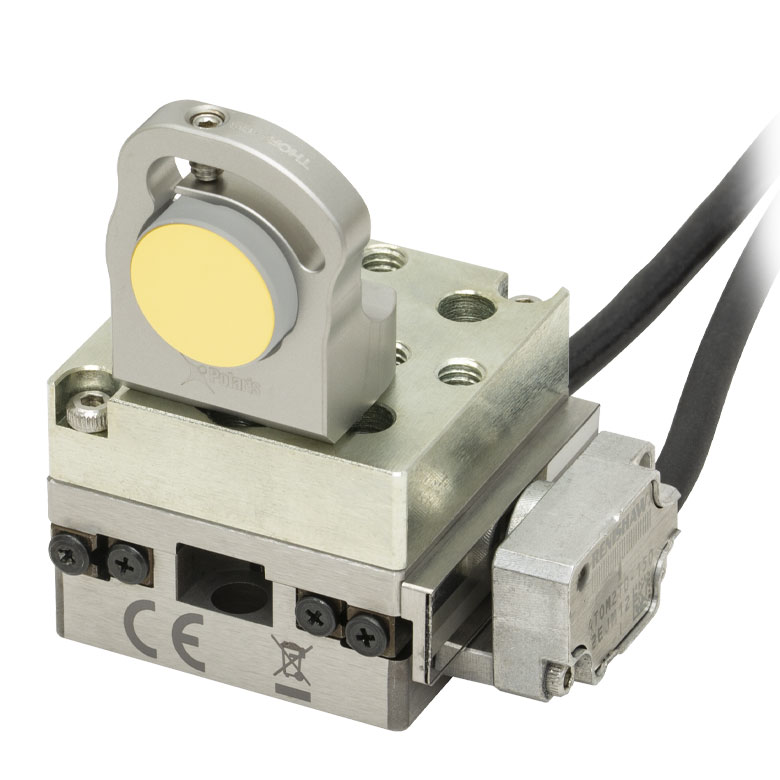
Click to Enlarge
Figure 804C ステージPDX1(/M)上のアダプタープレートPD1U(/M)に取付けられた固定式マウントPOLARIS-B05Sとミラー
Click for Details
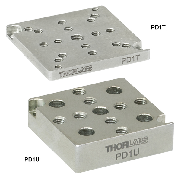
Figure 804A アダプタープレートPD1TとPD1T/Mの概略図
Click for Details
Figure 804B アダプタープレートPD1U(/M)の概略図。ミリ規格のアダプタープレートの寸法は括弧内に記載されています。
- 異なる取付け穴のパターンを提供
- 大きさは30 mm x 30 mmのピエゾステージに一致
- 各アダプタにはM2取付けネジとØ2 mm位置決めピンが2本ずつ付属
こちらのアダプタープレートをページ内のステージに取付けることで、取付け穴のパターンを変更することができます。各アダプタの大きさはステージと一致しており、付属する2本のM2キャップスクリュと四隅にある取付け用ザグリ穴を用いて、ステージ上部または底部に固定できます。
アダプタープレートPD1T/Mは中央にM4タップ穴と、取付け用のM2タップ穴が10個、M3タップ穴が4個、および16 mmケージシステム用に配置された#4-40タップ穴が4個あります。
アダプタープレートPD1U/Mには8個のM4タップ穴が十字型に配置されています。また、底面には5個のM4用ザグリ穴と、アライメントのために4個のØ2 mm位置決めピン用の穴があります。詳細はFigure 804Bをご覧ください。

 ズーム
ズーム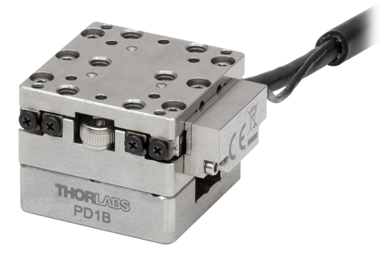
Click to Enlarge
Figure G3.3 UDX1 Stage Mounted to PD1B Adapter
Click for Details
Figure G3.2 PD1B2(/M) Mounting Adapter Schematic. Dimensions for the metric stage are given in parentheses.
Click for Details
Figure G3.1 PD1B(/M) Mounting Adapter Schematic. Dimensions for the metric stage are given in parentheses.
- Provide Flat Surface for Mounting PD1(/M), PD1V(/M), PDX1(/M), PDX1A(/M), PDX1AV(/M), or UDX1(/M) Stages
- Two Versions Available:
- PD1B(/M): #8 (M4) Mounting Slot
- PD1B2(/M): 1/4" (M6) Mounting Slots and 1/4"-20 (M6 x 1.0) Threaded Mounting Hole
- Reduces Stage Warping When Mounting to Table or Breadboard
These adapters provide a flat surface for mounting the stages above. The PD1B(/M) adapter features a #8 (M4) mounting slot and the PD1B2(/M) adapter features 1/4" (M6) mounting slots and a 1/4"-20 (M6 x 1.0) threaded mounting hole. If the stage is mounted on a surface with >5 µm flatness (as with most breadboards and optical tables), the velocity variation and pitch/yaw of the stage may suffer due to the stage warping. Mounting the stage on these adapters drastically reduces the amount the stage warps when mounted on a table or breadboard with insufficient flatness.
The stage can be mounted to the adapter using two 2-56 (M2 x 0.4) screws near the corners with a maximum of 0.35 N·m torque. Alternatively, two 8-32 (M4 x 0.7) screws can be used on either end of the stage with up to 0.55 N·m torque. To mount the PD1B(/M) to a breadboard, two SH8S025 (SH4MS06) 8-32 (M4 x 0.7) cap screws and two W8S038 #8 (M4) washers can be used. To mount the PD1B2(/M) to a breadboard, two SH25S038 (SH6MS10) 1/4"-20 (M6 x 1.0) and two W25S050 1/4" (M6) washers can be used.

 ズーム
ズーム
Click for Details
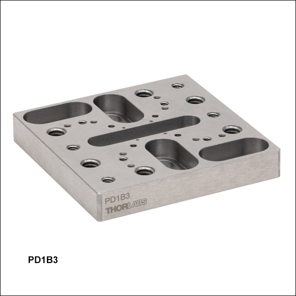
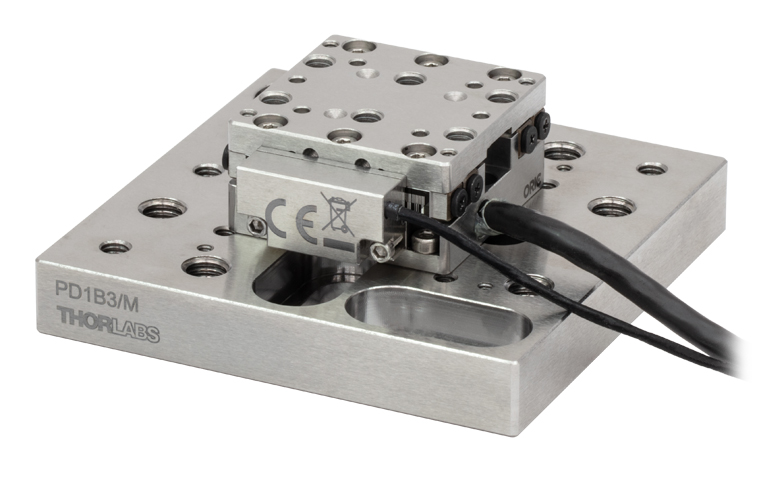
Figure G4.2 Mechanical Drawing for the PD1B3(/M) Adapter Plate. See Table G4.3 for descriptions of the hole labels. Dimensions for the metric version of the adapter plate are given in parentheses.
Click to Enlarge
Figure G4.1 UDX1/M Stage Mounted to PD1B3/M Adapter
- Provide Flat Surface for Mounting ORIC Stages
- Passivated Stainless Steel Construction
- Reduces Stage Warping When Mounting to Table or Breadboard
- Dimensions (L x W x H): (65.0 mm x 65.0 mm x 10.0 mm)
Thorlabs' PD1B3(/M) Universal Adapter Plate provides a flat surface (flatness ≤5 µm) for mounting any of the ORIC piezo stages. Mounting holes are labeled in Figure G4.2 corresponding to Table G4.3. The four 4-40 threaded holes are 30 mm cage system compatible, and two 1/4"-20 (M6 x 1.0) screws are included for mounting to breadboards.
If the stage is mounted on a surface with >5 µm flatness (as with most breadboards and optical tables), the velocity variation and pitch/yaw of the stage may suffer due to the stage warping. Mounting the stage on the adapter drastically reduces the amount the stage warps when mounted on a table or breadboard with insufficient flatness.
| Table G4.3 Mounting Holes | ||||
|---|---|---|---|---|
| Labela | Holes/Slots Patternb | Spacingb (Stage Compatibility) | Threading Depth | Places |
| A | 1/4"-20 (M6 x 1.0) | 1" x 2" (25 x 50 mm) | Through | 6 |
| B | Ø2 mm Dowel Pin Holes |
16 x 16 mm (Item #s PDXZ1(/M), PD1(/M), PD1V(/M), PD1D(/M), PDX1(/M), PDX1A(/M), PDX1AV(/M), PD3(/M), PDX3(/M), PDR1C(/M), UDX1(/M)) | 1.5 mm | 4 |
| C | 4-40 | 30 x 30 mm (Item #s PDR1(/M), PDR1V(/M)) | 3.5 mm | 4 |
| D | 1/4" (M6) Counterbored Slot | 1" to 2" (25 to 50 mm) | N/A | 4 |
| E | 00-90 (M1.2 x 0.25) | 10 x 10 mm (Item #s PD2(/M), PDX2(/M), PDX4(/M)) | 3 mm | 4 |
| F | #8 (M4) Counterbored Slot | 1.25" (31.25 mm) | N/A | 1 |
| G | 2-56 (M2 x 0.4) | 27.0 x 23.4 mm (Item #s PDXZ1(/M), PD1(/M), PD1V(/M), PD1D(/M), PDX1(/M), PDX1A(/M), PDX1AV(/M), PDR1C(/M), UDX1(/M)) / 40.8 x 30 mm |
7 mm | 8 |
| H | 8-32 (M4 x 0.7) | 1" (25 mm) (Item # UDX1(/M)) 2" (50 mm) (Item #s PD3(/M), PDX3(/M)) / 2" x 2" (50 x 50 mm) (Item # PDXR1(/M)) |
7.8 mm | 4 |

 ズーム
ズーム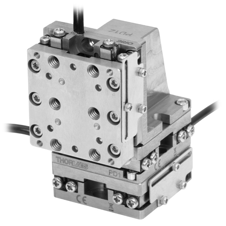
Click to Enlarge
Figure 805B アダプタPD1Z(/M)を用いると、3台のPD1(/M)でXYZステージを構成できます。
Click for Details
Figure 805A 直角ブラケットの垂直面。ミリ規格のブラケットの寸法は括弧内に記載されています。
- 1軸ステージ同士を接続して、2軸または3軸ステージを構成
- ステージを垂直面に取り付けて、垂直または水平方向の移動が可能
- 取付け用のM2ネジが2本付属
直角ブラケットPD1Z/Mを用いてページ内の1軸ステージを垂直方向に取り付けることで、Z軸ステージや、XZまたはXYZステージを構成することができます。このブラケットは、底面のコーナー近くの2つの取付け用ザグリ穴を2本のM2キャップスクリュで固定することで、ブレッドボードやステージの上部プレートに取付けられます。垂直用のステージは、付属のM2キャップスクリュ2本と、ステージの四隅のうちの2か所にある取付け用ザグリ穴を用いて、ブラケットに取り付けることができます。精密にアライメントできるように、各面にはØ2 mm位置決めピン用の穴があります。
ピエゾステージを直角ブラケットに取り付けると、垂直または水平方向に移動が可能になります。そのようにして構成した1軸ステージを、ブラケットのM4用ザグリ穴を用いてアダプタPD1B/M、PD1B2/M、またはPD3B/Mに取り付けると、光学テーブルまたはブレッドボードに取付け可能なZ軸ステージを構成することもできます。
XYZステージを構成した場合、垂直ステージを移動させた時に、下側のステージの固定プレートと干渉する可能性がありますのでご注意ください。3方向すべてについて全移動範囲を確保したい場合には、固定プレートを取り外してください。
注:垂直方向に取り付けた状態で長期間(>30億ステップ)使用すると、レールがクリープし、移動距離が減少することがあります。これを防ぐために、垂直方向でおよそ10億ステップ使用したら、ステージを水平に置いて全移動範囲にわたって前後に数回動かしてください。モノリシック構造のステージPD1D/Mを垂直方向に取り付けることは推奨しません。1つの軸がレールに対して横方向の力を受けるため、レールの角度誤差に影響が及ぶだけでなく、レールの寿命短縮につながる場合もあります。

 ズーム
ズーム
Click for Details
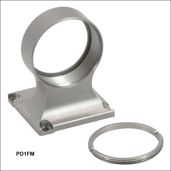
Figure 802A Mounting Holes on the PD1FM Optic Mount
- Compatible with All PD1 Series and UDX1(/M) 20 mm Piezo Stages
- Vertically Centers an Optic Along the 30 mm Cage System Optical Axis when Used with the PD1(/M) or PD1V(/M) Stage and the XPCM1(/M) Cage System Mount
- Mount Optic at 0 or 90° to the Stage's Translation Axis
- SM1-Threaded Optic Bore with Included POLARIS-SM1RR Retaining Ring
- Mounts Ø1" Optics up to 0.28" (7.1 mm) Thick
The PD1FM Fixed Optic Mount is designed to mount a Ø1" optic along the optical axis of a 30 mm cage system when used with a PD1(/M) or PD1V(/M) stage and XPCM1(/M) mount.
Note that the XPCM1(/M) cage mount and PD1FM Ø1" optic mount can be used together with the PDX1(/M) and UDX1(/M) stages but the optic will not be centered along the cage system's optical axis. The PD1D(/M) XY stage cannot be used with the cage mount and Ø1" optic mount at the same time. The PD1FM optic mount can be used with all PD1 series and UDX1(/M) stages outside of a cage system.
The base plate has two pairs of #2 (M2) counterbored mounting holes and four 0.07" (1.8 mm) deep alignment pin holes for mounting at 0 or 90° to the translation axis of the stage, enabling z- or x-axis adjustment; two Ø2 mm alignment pins are included with the PD1FM mount. When incorporated into a 30 mm cage system using a PD1(/M) stage mounted on the stage to cage mount above, the full 20 mm translation range of the PD1(/M) or PD1V(/M) stage is achievable in the z direction while the cutouts in the sides of the PD1FM mount provide clearance for ±3 mm of movement along the X-axis.
The optic bore has 0.36" (9.1 mm) deep SM1 (1.035"-40) threads and can hold optics up to 0.28" (7.1 mm) thick when used with the included POLARIS-SM1RR retaining ring.

 ズーム
ズーム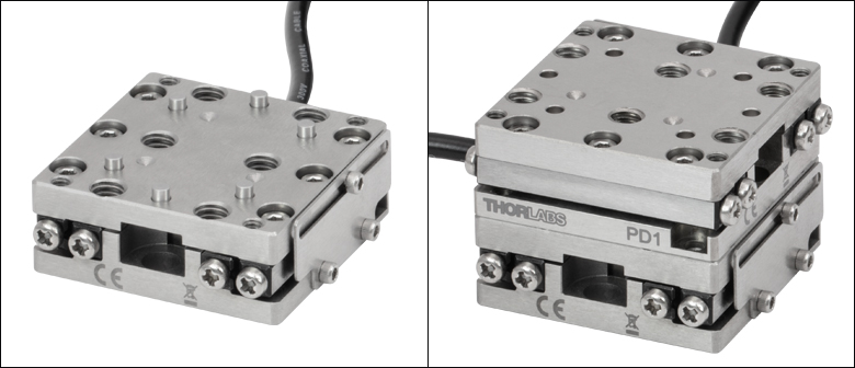
Click for Details
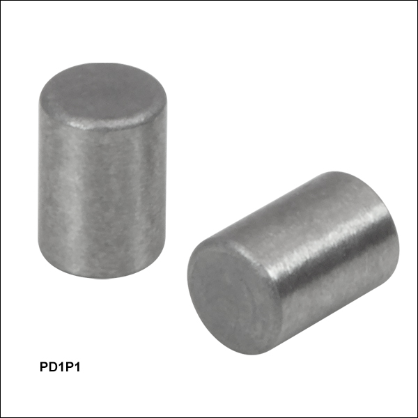
Figure 753A 上のステージPD1の写真に示すように、位置決めピンPD1P1はほとんどのORIC®ステージの取付け穴に適合します。
- Ø2 mm、長さ3 mmの位置決めピン
- 耐食性のあるステンレススチール製
- 20個セットでご用意
位置決めピンPD1P1の寸法は、直径2 mm、長さ3 mmです。この製品は、当社のORIC®ステージ(4.5 mm垂直移動ステージ、20 mmおよび50 mm直線移動ステージ、回転ステージ、真空対応ステージ)に付属する位置決めピンの交換用としてご使用いただけます。ステンレススチール製で耐食性があります。
20個セットでご用意しております。

 ズーム
ズーム| Key Specificationsa | ||
|---|---|---|
| Performance Specificationsa | ||
| D-Sub Port | Number of Ports | One |
| Voltage | 0 to 30 V | |
| Frequency | 220 kHz Max | |
| Max Current Limit | 8 A | |
| Front USB | Type A, USB HID Host | |
| Back USB | Type B, USB Device 2.0 | |
| I/O Port | Voltage of Analog In/Out | -10 to 10 V, ±2% |
| Voltage of Trigger In/Out | 0 to 5 V, TTL | |
| Ethernet PC Communication | One RJ-45 Port | |
| Dimensions (L x W x H) | 115.2 mm x 150.0 mm x 48.5 mm (4.54” x 5.91” x 1.91”) |
|
| Weight | 0.33 kg | |
| Input Power | 12 VDC, 3 A | |
- For complete specifications, please see the manual by clicking the red Docs icon (
 ) below.
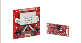
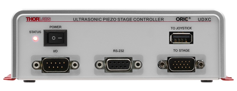
- Controller for ORIC Ultrasonic Piezoelectric Drive Linear Stages
- Compact Design and PC Control with Kinesis® Software
- Supports Closed-Loop Operation
- Energy Efficient Switch Amplifier Circuit Outputs Peak Current of 10 A
- Configurable High Speed Communication Interfaces: USB 2.0, Gigabit Ethernet, Digital I/O, Analog I/O
- Max Drive Frequency of 220 kHz
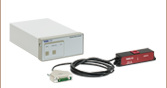
The UDXC compact controller is designed for our UDX1(/M) ORIC ultrasonic piezoelectric drive linear stage. It features one channel that supports closed-loop stage control using a 15-pin D-Sub output.
The UDXC controller is connected to PC by either the USB or ethernet ports on the back panel of the controller. All the operating parameters and operations, such as performing homing operation and parameter optimization, are controlled by PC with the Kinesis® software (available for download in the Kinesis Software tab). Settings such as trigger modes and movement parameters can be configured for operations such as raster scans. Please see the user manual for details. Command-line control is also possible through the USB and RS-232 ports.
The UDXC control unit is powered by the included DS12 12 VDC power adapter, which operates at an input voltage of 100 - 240 VAC and ships with a region-specific AC cable. For all applications, use an IEC320 compatible power cord fitted with a plug appropriate for your particular power socket. Make sure that the line voltage rating marked on the power adapter agrees with your local power supply.

 ズーム
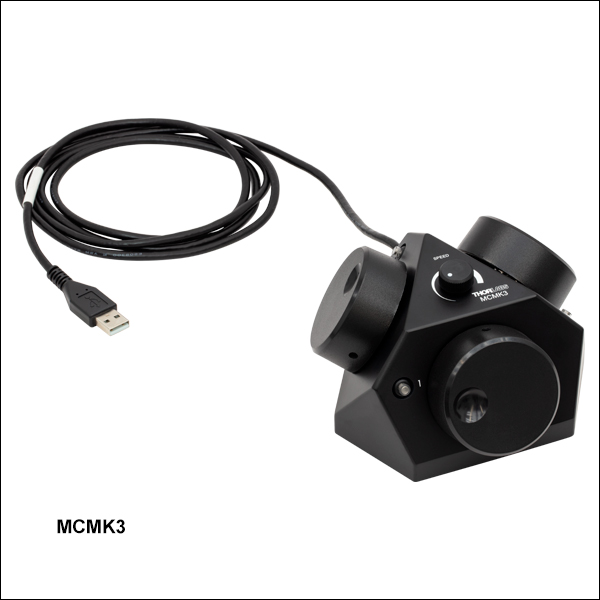
ズーム- 標準的なUSB HIDプロトコルを使用
- ノブで最大3軸までの手動制御が可能
- 感度調整のための速度ダイヤル付き
ジョイスティックMCMK3は、3つのノブとUSBケーブルが付いた手動操作ボックスです。ジョイスティックの3つの側面には、それぞれ回転ノブとプッシュボタン式のLEDスイッチがついています。HIDジョイスティックをコントローラUDXCの前面パネルのUSBコネクタに接続すると、ジョイスティックを用いてステージを制御することができます。移動速度とステップサイズは、Kinesis GUIの設定パネルでジョグパラメータを調整して設定できます。ジョイスティックはUSB HIDデバイスで、電力はUSBケーブル経由で供給されます。
ジョイスティックMCMK3は、HIDクラスを使用するあらゆるデバイスにご使用いただけます。詳細はこちらの製品ページをご覧ください。ジョイスティックのHIDレポートに関するトラブルシューティングや試験に有用なテストユーティリティについては、「USB HID Joystick Software」のページをご覧ください。