 Products Home
ステッピングモータ用小型コントローラ、Cernaコンポーネント用
- Operate Motorized Microscopy Stages and Components
- 7.0 A Peak Current Output
- Three Channel Control via Software or Three-Knob Joystick
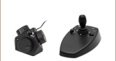
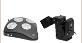
MCMK3
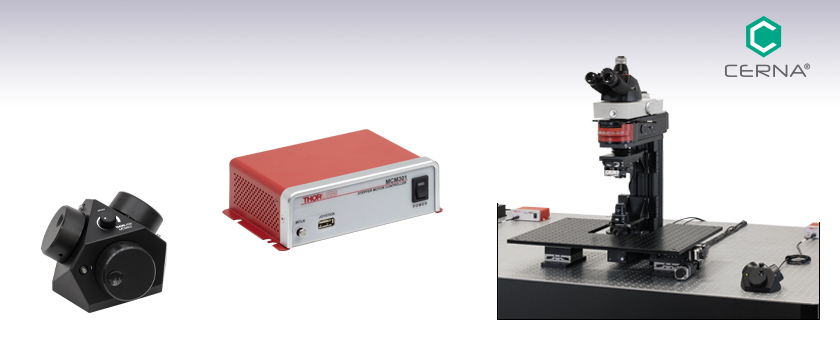
3-Knob Joystick
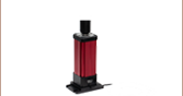
MCM301 Used to Control
the PMP2XY Cerna®
Translating Platform
MCM301
Compact Controller for Motorized Rigid Stands and PLS Series Stages


Please Wait

| Table 1.1 Compatible Stages |
|---|
| MPM250(/M) Motorized Rigid Stand PLSX & PLSXY Translation Stages for Rigid Stands PLSZ Motorized Focusing Module PMP2XY(/M) XY Translation Platform MMP2XY Microscope Body Translator |
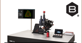
Click to Enlarge
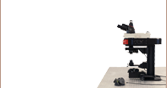
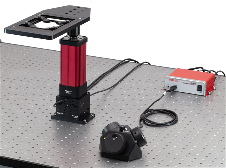
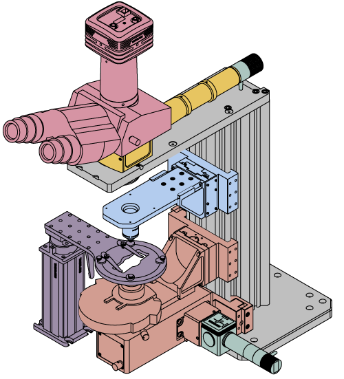
Figure 1.3 コントローラMCM301と3ノブ型ジョイスティックMCMK3を用いて、移動ステージPLSXYの2軸と電動高剛性スタンドMPM250(/M)の1軸を制御しています。
特長
- 電動型の顕微鏡ステージやコンポーネントの操作
- 独立したソフトウェアで同時に最大3チャンネルまで制御可能
- 各軸は個別に無効にすることができ、それにより意図しない動きの防止や位置の保持が可能
- 3ノブ型ジョイスティックMCMK3(別売り)による手動操作が可能
- ジョイスティック上部のダイヤルで移動速度を調整
ステッピングモーターコントローラMCM301は、独立したソフトウェアを用いてTable 1.1に記載されている電動の顕微鏡ステージやコンポーネントをリモート操作できるように設計されています。3ノブ型ジョイスティックMCMK3(別売り)を接続して、手動操作も可能です。コントローラMCM301はプラグアンドプレイ機能を有し、対応するステージが接続されたことを自動的に検出して操作を開始できます。インターロック回路が内蔵されており、インターロック用のジャックがコントローラの前面パネルに付いています。
コントローラMCM301には3つのチャンネルがありますので、使用するモジュールのチャンネル数に応じて必要な台数をご購入ください。例えば、垂直移動型高剛性スタンドMPM250(1軸)と移動ステージPLSXY(2軸)を用いる場合は、1台のコントローラMCM301で十分です。
移動の制御は、ソフトウェアを介してリモートで行うこともできます(詳細は「ソフトウェア」タブをご覧ください)。また、このコントローラをカスタム仕様のイメージングソフトウェアに組み込めるように、LabVIEW™、C++およびPython用のソフトウェア開発キット(SDK)とサポート文書をご用意しています。
コントローラには電源と国内用電源コードが付属します。交換品として電源DS24をご用意しています。
ジョイスティックの操作
3ノブ型ジョイスティックMCMK3の3つの面には、それぞれ各軸用の回転式ノブと押しボタン式のスイッチが付いています。押しボタン式のスイッチで制御の有効・無効を切り替えられます。有効のときは緑色に点灯します。無効にするとその軸の位置を保持するとともに、意図しない動きを防止します。ジョイスティック上面のダイヤルで、ノブの回転に対する接続機器(ステージ等)の動作速度を調整できます。3ノブ型ジョイスティックMCMK3の詳細やUSB HIDプロトコルの使用方法については、製品ページをご覧ください。なお、3ノブ型ジョイスティックMCMK3はコントローラMCM301に対応する唯一のジョイスティックです。
| Item # | MCM301 |
|---|---|
| Motor Output | |
| Motor Drive Voltage | 24 V |
| Motor Drive Current | 7.0 A (Peak), 3.0 A (RMS) |
| Motor Drive Type | 12-Bit PWM Control |
| Control Algorithm | Open/Closed-Loop Microstepping |
| Stepping | 128 Microsteps per Full Step |
| Encoder Resolution | - |
| Total Steps per Revolution | - |
| Maximum Stepping Velocity | - |
| Position Feedback | 5 V Quadrature Encoder (QEP) Input |
| Encoder Feedback Bandwidth | 1 MHz |
| Position Counter | 32 Bit |
| Operating Modes | Position and Velocity |
| Velocity Profile | Trapezoid |
| Motor Drive Connector | |
| Mechanical Specifications | 15 Position D-Type, Female Pin Connector |
| Motor Drive Outputs | Phase A and B |
| Quadrature Encoder (QEP) Input | Single Ended |
| Limit Switch Inputs | Forward, Reverse (+ Common Return) |
| Encoder Supply | 5 V |
| Input Power Requirements | |
| Voltage | 24 VDC |
| Current | 6.67 A |
| General | |
| Computer Connection | USB 2.0 |
| Housing Dimensions (W x D x H) | 5.91" x 4.52" x 1.91" (150.0 mm x 114.8 mm x 48.5 mm) |
| Compatible Motor Specifications | ||
|---|---|---|
| Motor Type | 2-Phase Bi-Polar Stepper | |
| Rated Phase Current | Up to 7 A Peak | |
| Coil Resistance (Nominal) | 5 to 20 Ω | |
| Position Control | Open or Closed Loop | |

コントローラMCM301用ソフトウェア
コントローラMCM301用のソフトウェアとファームウェアの最新版は、下のリンクからダウンロードいただけます。ダウンロードページでは、GUI、ドライバ、サードパーティ開発支援用のSDK(LabView™、C++、Python)をダウンロードできます。
Click to Enlarge
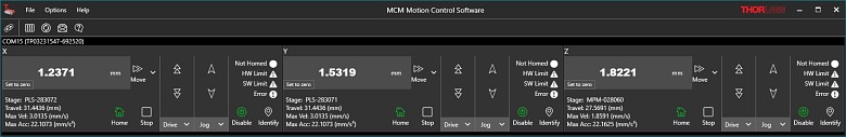
Figure 4.1 コントローラMCM301用ソフトウェア
ソフトウェア
バージョン 1.2.1(2025年1月30日)
ソフトウェアパッケージにはグラフィカルユーザーインターフェイス(GUI)、ドライバ、およびSDKが含まれます。ソフトウェアはWindows® 10(64ビット)とWindows® 11(64ビット)のシステムに対応しています。

Click to Enlarge
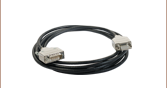
Figure 5.1 MCM301製品内容
MCM301には下記のコンポーネントが含まれます。
- コントローラーボックス
- 電源、日本国内用電源コード付き
- USBケーブル(A-B)
注: MCM301にはノブボックスは含まれません。対応する3軸ジョイスティックMCMK3を別売りでご用意しております。
| Posted Comments: | |
Jiaze Yin
(posted 2025-04-10 16:29:24.897) Hi,
We are using the MCM3001 with PLS-XY stage. I can connect with the software, however, as I try to connect with LabView, it can not be connected subvi Find Device return 0.
Thanks for helping to solve this issue.
Best
Jiaze EGies
(posted 2025-05-02 03:41:34.0) Thank you for contacting Thorlabs. I have reached out to you directly regarding further troubleshooting steps. seonghwan kim
(posted 2023-12-05 09:10:48.057) Good morning, I am using the MCM3000 and MCM3001 with a PLS-XY stage. I want to control them using LabVIEW. Therefore, I utilized your SDK (MCM3000, v.40) and example. However, I am encountering an issue at the initial step. When I attempt to use the 'Find device.vi,' it fails to detect the device. I am utilizing it with COM32, and when I use your MCM3000.exe, it operates correctly. Best, Kim. cdolbashian
(posted 2023-12-13 03:36:49.0) Thank you for reaching out to us with this inquiry! I think perhaps the example code you are using might not be the most up-to-date one. I have reached out to you directly with the correct example. Peter Doyle
(posted 2023-09-05 09:29:00.307) Goop Morning,
It would be very helpful to be able to buy replacement cables. I am particularly interested in replacement joystick cables.
Best Regards,
Peter Doyle cdolbashian
(posted 2023-09-11 01:38:40.0) Thank you for reaching out to us with this inquiry! We can certainly sell you the cables you need directly, even if they aren't on the web catalogue. I have contacted you directly to facilitate this. For future similar inquiries, please contact techsupport@thorlabs.com. Qu Zhelin
(posted 2022-09-22 16:48:31.08) We misplaced the power adapter of MCM3001, now we need to buy it again, but we don't know its model, we can only judge its company by the "MW" on the picture, could you please tell us the model of the power adapter? ksosnowski
(posted 2022-09-26 11:12:32.0) Hello Qu, thanks for reaching out to Thorlabs. We can quote replacement power supply accessory for the MCM3001 as a special item. These requests can be directed to techsupport@thorlabs.com or your region's local tech support team. I have reached out directly to discuss this further. Chia-Hsien Lin
(posted 2020-02-10 21:41:00.333) Hi,
I try to use Labview to control the MCM3002 control with the version 4.0 driver. Is it possible to control the motor speed in the Labview? On the other hand, even if I call the parameter "PARAM_X_VELOCITY_CURRENT" by the commend "GetParam()", the value will return zero.
Best,
Chia-Hsien llamb
(posted 2020-02-21 08:12:59.0) Thank you for your feedback. The software cannot adjust the speed of the connected stage. Only the Speed Control knob can adjust the speed of translation per rotation of each knob when using the 3-Axis Knob Box to manually control a connected stage, as speed control is hard-wired to this dial. I have reached out to you directly to discuss further. Dmytro Toptunov
(posted 2019-08-05 08:26:43.31) Good morning,
Does MCM3003 work with LNR50SE/M stages? They are also built around DRV014 stepper motor, but not mentioned in the MCM3003 supported equipment list.
Does MCM3003 support mixed configuration, e.g. 2 x LNR50S/M stages and 1 x LNR50SE/M stage?
Finally, could you please send an LabVIEW SDK and manuals?
Best regards,
Dmytro nbayconich
(posted 2019-08-16 08:43:31.0) Thank you for conctacting Thorlabs. The MCM3003 controller can be used with the encoded LNR50SE stages, the only downside is that the encoder can not be used with the MCM3003 controller. You can use a combination of either the LNR50S or LNR50SE just be aware that the encoder cannot be used with this particular controller, in order to have access to the encoders feedback you would have to use a controller like the BSC203 with the LNR50SE stages.
Our SDK can be downloaded directly from our webpage under the software download link below.
https://www.thorlabs.us/software_pages/ViewSoftwarePage.cfm?Code=MCM3000
I will reach out to you directly. Matthew Broome
(posted 2019-07-03 05:35:19.95) Does the SDK for this controller support integration with MatLab? asundararaj
(posted 2019-07-08 02:59:06.0) Thank you for contacting Thorlabs. At the moment, we do not have dedicated documentation/support for integration with MATLAB. However, we do have documentation for serial communication which can be used to integrate with MATLAB. I have reached out to you directly for further discussion. Seonho Shin
(posted 2019-05-27 00:30:41.94) 'MCM3001 and ZFS2020' seems to work only on Windows 7. It does not work well when run on Windows 10. When I ordered just '0.1mm' move, It keeps going until the upper limit.
It there other version of application or SDK which is compatible for Windows 10? YLohia
(posted 2019-06-13 08:51:25.0) Hello, thank you for contacting Thorlabs. We believe this to be a configuration issue rather than a software or hardware issue (and should not be dependent on the OS being used). Does the problem show up for any motion or just 0.1mm? What version of the software are you using? We reached out to you directly at the time of your original post to troubleshoot your issue. If you still have this problem, please send us an email with the screenshots of your GUI. chris
(posted 2017-07-21 16:19:51.013) +1 for adding the SDK/software/examples + manual to the website. Since it isn't there right now, could you send it to me directly? tfrisch
(posted 2017-07-26 11:43:08.0) Hello, thank you for contacting Thorlabs. It looks like our previous attempt to send you this file was returned because it contained a zip attachment. I will reach out to you directly about posting this in a place you can download it directly. craig
(posted 2017-01-11 12:30:26.1) The product MCM3001 has no manual available online. It would also be helpful if the SDK and LAbview examples were available for direct download rather than by contacting tech support. Your main office does not have any information to support this product and I was directed to contact the imaging group. tfrisch
(posted 2017-01-11 01:24:23.0) Hello, thank you for contacting Thorlabs. I will reach out to you directly about your application. |
顕微鏡の各部品をクリックするとそれぞれの機能がご覧いただけます。
顕微鏡の原理
ここではCerna®顕微鏡の一般的な機能について説明しています。右にある顕微鏡の図の各部品をクリックいただくか、下記のリンクをクリックいただくとCerna顕微鏡を組み上げて試料を可視化する方法についてご覧いただけます。
用語
アーム:部品を顕微鏡の光路に合わせて保持
バヨネットマウント:内ネジのL字型スロットとそれに嵌合する外ネジのタブを用いた機械的なマウント方式
ベローズ(蛇腹):アコーディオン状のゴム製側面を持つチューブ。顕微鏡ボディと対物レンズとの間の光路を遮光しながら伸縮させることが可能です。
ブレッドボード:光学系の自作用に、タップ穴が等間隔に配列された平坦なボード
アリ溝式:多数の顕微鏡部品に採用されている機械的な取付け方式。直線形状のアリ溝は、取り付ける部品を固定する前に一定の方向に沿って柔軟に位置決めができます。これに対し、円型アリ溝は部品を1箇所に固定します。詳細については「顕微鏡のアリ溝」タブまたはこちらをご覧ください。
落射照明:観察装置と同じ向きから試料を照らす照明。落射蛍光、反射型および共焦点顕微鏡は、落射照明で使用するイメージング手法の例です。
フィルターキューブ:フィルタやその他の光学素子を正確な位置で保持する顕微鏡用のキューブ。例えば、フィルターキューブは蛍光顕微鏡法および反射型顕微鏡法に不可欠です。
ケーラー照明:様々な光学素子を使用して試料面の視野内をデフォーカスしたり視野内における光の強度を平坦にしたりする手法。この手法にはコンデンサおよび光コリメータが必要です。
対物レンズ用ホルダ(レボルバ):顕微鏡の対物レンズを光路上に固定する際に使用するアーム
光路:光が顕微鏡を透過する際にとる経路
レール高:顕微鏡ボディのサポートレールの高さ
懐深さ(作業空間の奥行き):光軸から顕微鏡ボディのサポートレールまでの間の距離。懐深さのサイズは、作業高さとともに、顕微鏡を使用する際の作業空間の大きさを決定します
透過照明:観察装置に対して反対側の面から試料を照らす照明。明視野、微分干渉法(DIC)、Dodt勾配コントラスト、および暗視野顕微鏡法は、透過照明を利用したイメージング手法の例です。
作業高さ:顕微鏡ボディのサポートレール高にベース高を加えた高さ。作業高さのサイズは、懐深さとともに、顕微鏡を使用する際の作業空間の大きさを決定します。
 Click to Enlarge
Cerna顕微鏡のボディ
Click to Enlarge
顕微鏡ボディの詳細
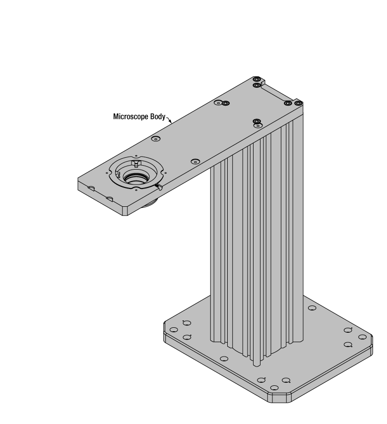
顕微鏡ボディ
顕微鏡ボディはあらゆるCerna顕微鏡の土台となります。 サポートレールに使用している95 mmレールは、厳しい角度公差が得られるよう加工されているため、光路のアライメントや光学テーブルへの垂直な設置が確実に行えます。サポートレールの高さは350~600 mmから選択できますが、この高さによって実験用・顕微鏡用部品を使用できる縦方向の空間の大きさが決まります。 光路からサポートレールまでの懐深さは196.5 mmあるため、広い実験用スペースが得られます。顕微鏡ボディに部品を取り付ける際はサポートレール上の直線的なアリ溝を使用しますが、部品によっては落射照明アーム上の円型アリ溝が使われます。 詳細については、「顕微鏡のアリ溝」タブまたはこちらをご覧ください。
 Click to Enlarge
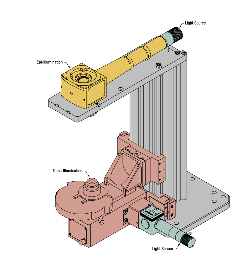
Cerna顕微鏡には、上から(黄色)または下から(オレンジ)照射するタイプの照明が使用可能です。どちらのタイプにも照明光源(緑)が付いています。
照明
Cerna顕微鏡では、試料を上から(落射照明、右図で黄色に色付けされた部品参照)または下から(透過照明、オレンジ色に色付けされた部品参照)の2方向から照射することができます。
落射照明は、観察装置と同じ側から試料を照らす照明です。したがって、照明光源(緑色に色付けされた部品参照)からの光と試料面からの光は部分的に光路を共有します。これは蛍光、共焦点および反射型顕微鏡に使用されます。落射照明モジュールは光を光路に沿って導き調節します。円型のD1Nアリ溝を使用して顕微鏡ボディの落射照明アームに取り付けます(詳細については「顕微鏡のアリ溝」タブまたはこちらをご覧ください)。複数の落射照明モジュールや、カスタマイズ用のタップ穴が等間隔で配列されたブレッドボードトップを取り付けることができます。
透過照明:観察装置に対して反対側の面から試料を照らす照明です。明視野、微分干渉法(DIC)、Dodt勾配コントラスト、斜光および暗視野顕微鏡法などのイメージング手法に使用されます。 透過照明モジュールは光を調節し(一部のモデル)、光路に沿って光を導きます。直線的なアリ溝を使用して顕微鏡ボディのサポートレールに取り付けます(詳細については「顕微鏡のアリ溝」タブまたはこちらをご覧ください)。イメージング手法によっては、ビーム特性を変更するために追加の光学素子が必要となりますが、このような光学素子は、レンズチューブやケージシステムを使用して光路に簡単に組み込むことができます。また、当社では、入射したコリメート光から最適なケーラー照明を生むために使用するコンデンサもご用意しています。コンデンサは取付けアームに装着し、サポートレールから一定の距離の光路上に固定します。このアームは、コンデンサを試料と透過照明モジュールにアライメントするための焦準モジュールに取り付けます。
 |  |  |  |  |  |  |  |
| Epi-Illumination Modules | Breadboards & Body Attachments | Brightfield | DIC | Dodt | Condensers | Condenser Mounting | Light Sources |
 Click to Enlarge
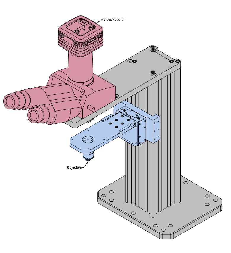
試料面からの光は対物レンズ(右図で青色に色付けされた部品)によって集められ、三眼鏡筒または光学ポート(ピンク色に色付けされた部品)を使用して観察されます。
試料の観察/記録
照明ができたら、顕微鏡を使用して試料を観察します。顕微鏡には試料面に光を集光し(右図で青色に色付けされた部品参照)、生成した画像を可視化する(ピンク色に色付けされた部品参照)機能が必要です。
顕微鏡の対物レンズは、光を集め、試料面からの光を拡大してイメージングを行います。Cerna顕微鏡の対物レンズは対物レンズ用レボルバ(ホルダ)にネジ止めされ、顕微鏡ボディのサポートレールから一定の距離の光路上に固定します。対物レンズ用レボルバ(ホルダ)は電動焦準モジュールに固定し、対物レンズの焦点を合わせたり、試料を取り扱う際に対物レンズの位置をずらしたりすることができます。対物レンズとの間を遮光できるように、顕微鏡にはベローズが付いています(図には記載なし)。
試料観察およびデータ取得用に様々なモジュールをご用意しています。三眼鏡筒には視点が3箇所あり、カメラを使用した場合と同様に試料を直接観察できます。ダブルカメラポートが2つの観察チャンネル内で光路を変更または分岐します。カメラチューブの選択により像の倍率を低く、もしくは高くさせることができます。データ取得用に、当社ではカメラおよび光電子増倍管チューブ(PMT)をご用意しています。PMTは共焦点顕微鏡の蛍光信号を検出する際に必要です。ブレッドボードトップを使えばカスタム設計の撮像セットアップを構築できます。モジュールは円型アリ溝を使用して顕微鏡ボディに取り付けます(詳細については「顕微鏡のアリ溝」タブまたはこちらをご覧ください)。


 Click to Enlarge
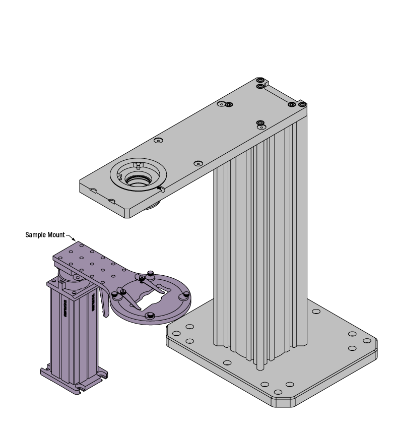
右図の高剛性スタンド(紫色)はご提供可能な試料取付けオプションの1例です。
試料/実験機器の取付け
様々な試料や機器の取付けオプションによって、顕微鏡システムの広い作業スペースを有効利用することができます。大きな試料および補助装置は取付けプラットフォームを使用して設置することができます。このプラットフォームは顕微鏡ボディの辺縁に置くことができ、タップ穴が等間隔で配列されたブレッドボードに対応しています。小さな試料は高剛性スタンド(右図の紫色に色付けされた部品)に取り付けることができます。高剛性スタンドには多様な試料調製法やデータ取得手法に対応したホルダが付属しており、たとえばスライドやウェルプレート、ペトリ皿などに対応できます。一般的な試料マウント方法の場合は、手動XYステージを使用して試料スライドを顕微鏡ボディに直接取り付けることもできます。高剛性スタンドは電動ステージ(別売り)を用いて駆動できます。また可動型取付けプラットフォームには電動または手動移動用の機構が内蔵されています。顕微鏡で複数の実験を同時に行いたい場合は、高剛性スタンドを取付けプラットフォームの上部に取り付けて、複数の装置を個別にかつ同期させて動作させることができます。
 |  |  |  |  |
| Translating Platforms | Rigid Stands | Translation Stages for Rigid Stands | Motorized XY Stages | Manual XY Stage |
試料観察用に三眼鏡筒、ダブルカメラポートならびにカメラチューブをご用意しています。試料面からの光はカメラ、光電子増倍管(PMT)またはブレッドボードトップを用いたカスタム仕様のセットアップによって集光されます。Cerna顕微鏡を用いた試料観察についての詳細はこちらをクリックしてください。
| Product Families & Web Presentations | |||
 | |  |  |
| Sample Viewing | Breadboards & Body Attachments | Cameras | PMTs |
顕微鏡用対物レンズは、対物レンズ用レボルバ(ホルダ)によって顕微鏡の光路内に固定されます。Cerna顕微鏡を用いた試料観察についての詳細はこちらをクリックしてください
| Product Families & Web Presentations | ||||
 |  |  |  |  |
| Objectives | Objective Thread Adapters | Parfocal Length Extender | Piezo Objective Scanner | Objective Mounting |
大型または小型の実験用取付けオプションを使用して、顕微鏡の広い作業スペースを有効利用することができます。Cerna顕微鏡を用いた試料取付けについての詳細はこちらをクリックしてください。
| Product Families & Web Presentations | ||||
|  | | |  |
| Translating Platforms | Rigid Stands | Translation Stages for Rigid Stands | Motorized XY Stages | Manual XY Stage |
落射照明用の様々な光源をご用意しています。Cerna顕微鏡プラットフォーム内での機能をご確認いただくには、各製品の説明ページをご覧ください。
| Product Families & Web Presentations | ||||
 |  |  |  | |
| Trans-Illumination Kits | Solis™ High-Power LEDs | Mounted LEDs | X-Cite® Lamps | Other Light Sources |
落射照明:観察装置と同じ向きから試料を照らす照明。蛍光、共焦点および反射型顕微鏡などのイメージング手法で使用されます。落射照明をCerna顕微鏡に用いる際の詳細については こちらをクリックしてください。
| Product Families & Web Presentations | ||
| | |
| Epi-Illumination | Body Attachments | Light Sources |
透過照明:観察装置に対して反対側の面から試料を照らす照明です。明視野、微分干渉法(DIC)、Dodt勾配コントラスト、斜光および暗視野顕微鏡法などのイメージング手法に使用されます。透過照明をCerna顕微鏡に用いる際の詳細についてはこちらをクリックしてください。
| Product Families & Web Presentations | ||||||
| | | |  | | |
| Brightfield | DIC | Dodt | Condensers | Condenser Mounting | Illumination Kits | Other Light Sources |
顕微鏡ボディはあらゆるCerna顕微鏡の土台となります。ボディから対物レンズまでの距離は196.5 mmで、広い実験用スペースが確保できます。Cerna顕微鏡についての詳細はこちらをクリックしてください。
| Product Families & Web Presentations | |
 |  |
| Microscope Bodies | Microscope Translator |