 Products Home
ハンドヘルド型デジタルパワーメーター&エネルギーメーターコンソール
- Power and Energy Measurements for Free Space and Fiber Applications
- Designed for High Accuracy, Reliability, and Ease of Use
- Over 25 Compatible Sensors
PM100D
Multiple Display
Options
Photodiode, Fiber, Integrating
Sphere, Thermal, and Pyroelectric
Sensors Available
Detector Options


Please Wait
| Item # | PM100D |
|---|---|
| Compatible Sensors | Photodiode, Thermal, and Pyroelectrica |
| Optical Power Rangeb | 100 pW to 200 W |
| Optical Energy Rangeb | 3 µJ to 15 J |
| Available Sensor Wavelength Rangeb | 185 nm - 25 μm |
| Max Repetition Rateb | 3 kHz |
| Display Refresh Rate | 20 Hz |
| Bandwidtha | DC - 100 kHz |
| Photodiode Sensor Rangec | 50 nA - 5 mA |
| Thermopile Sensor Rangec | 1 mV - 1 V |
| Pyroelectric Sensor Rangec | 100 mV - 100 V |
| Power Meter Selection Guide |
|---|
| Sensors |
| Photodiode Power Sensors |
| Thermal Power Sensors |
| Thermal Position & Power Sensors |
| Pyroelectric Energy Sensors |
| Power Meter Consoles |
| Digital Handheld Console |
| Analog Handheld Console |
| Touchscreen Handheld Console |
| Dual-Channel Benchtop Console |
| Complete Power Meters |
| Power Meter Bundles |
| Wireless Power Meters with Sensors |
| Compact USB Power Meters |
| Field Power Meters for Terminated Fibers |
| USB Interfaces, External Readout |
特長
- ハンドヘルドタイプのデジタルコンソール式パワーメータ
- コヒーレントとインコヒーレント光源の測定用に設計
- 連続波光源とパルス光源検知に対応したパワーとエネルギの測定
- 大型の4インチ液晶ディスプレイで複数の表示画面が選択可能
- 25種類以上のセンサに対応(下記参照)
- 取り付け済み8 GB SDメモリーカードでデータの保管と転送
- USB 2.0接続
- 長寿命のリチウムポリマ電池を内蔵
- センサのアップグレードおよび再校正サービスをご提供
- PCソフトウェアOptical Power Monitorをご用意(詳細は「ソフトウェア」タブをご参照ください)
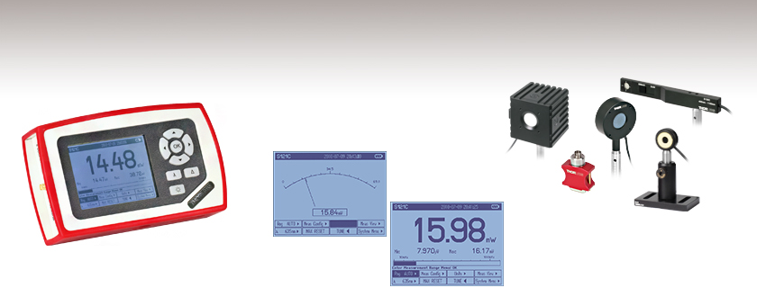
PM100Dは、当社の光パワーとエネルギ測定用コンソールの土台をなす製品で、アナログコンソール式パワーメータPM100Aのデジタル版です。このコンソール(別売りのセンサと組み合わせて使用)は、CWレーザやパルスレーザのパワーメータ、インコヒーレント光源のパワーメータ、その他一般的な光のパワーメータやファイバ用のパワーメータとして適しています。PM100Dのディスプレイは明るさの設定が調整でき、バックライトをオフにして表示を読み取ることができます。
PM100Dは、フォトダイオードセンサ、薄型フォトダイオードセンサ、積分球型フォトダイオードセンサ、ファイバ用フォトダイオードセンサ、サーマルセンサおよび焦電センサ を含む25種類を超えるUV域から中赤外域対応のセンサと互換性があります。詳しい情報については、「センサの互換性」のタブをご覧ください。
パワー&エネルギーメーターコンソールは、当社でもニーズの高いセンサと組み合わせたキットとしてもご提供しています。詳細についてはパワーメーターキット のページをご覧ください。このキットについてご質問がある場合、もしくは新たなキットに対するご要望については、当社までご連絡ください。
さらに優れたスペクトル補正機能、温度および湿度センサ入力、データロギング、追加メモリを備えたPM100Dのタッチパネル版、マルチタッチ対応パワー&エネルギーメーターコンソールPM400をご提供しています。また、OLEDディスプレイ、Bluetooth®、USB接続機能を備えた、超薄型ワイヤレス機能付きハンドヘルド型パワー&エネルギーメータもご提供しています。
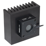
コンソール設計
この小型筺体には、暗い実験室でも簡単に操作できるように、解像度320 x 240ピクセルの大型4インチのバックライト付きディスプレイと照明ボタンが付いています。LCDの鮮明なGUIは、直感的なナビゲーションの配列をしており、簡単にデータを読み取ることができます。スクリーンには、次のステップの指示が表示されるので、段階的な操作指示に従いながら装置を操作できます。
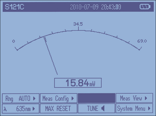
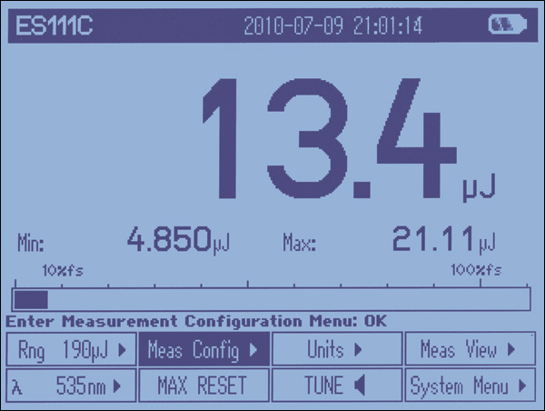
PM100Dには4つの標準仕様の測定画面があります。1番目の画面は、読み取り数値表示画面で、通常のパワーやエネルギの測定値の読み取りに便利です。2番目の画面は、アナログ式の装置を模した調整用の針が表示される画面ですが、デジタル測定数値が表示できるように最適化されています。3番目の画面では、チューニング用のグラフが表示されて、CWレーザやパルスレーザ光源の精密調整に非常に便利です。
このユニットはデータ取得モードで動作することもできます。スキャンを始動させると、データ取得期間中のパワー、エネルギ、最小/最大/標準偏差等の重要なデータを、装置が特別な操作なしに記録しはじめます。この他にPM100Dには、複数のカスタム設定可能な表示画面や画面が見えない場合のための音声機能があります。「画面表示」のタブ内には、さらに詳しい情報が記載されています。
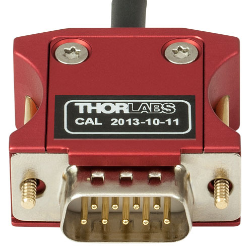
Click to Enlarge
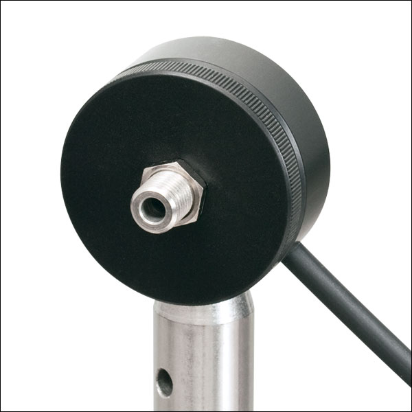
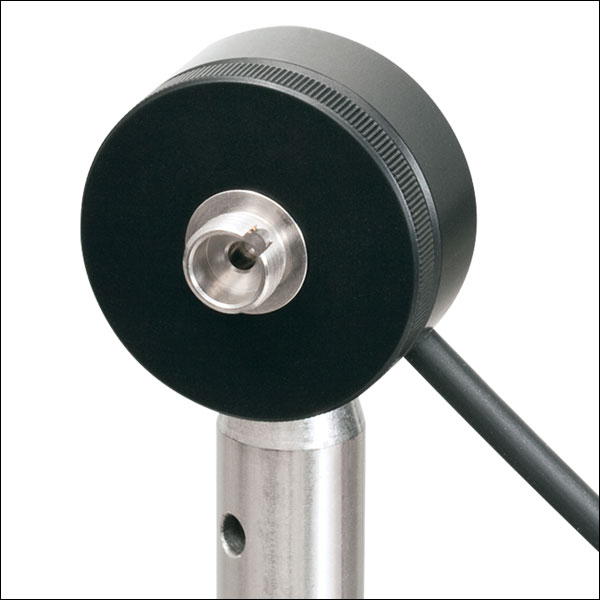
Cシリーズのパワーメーターセンサのコネクタにはセンサの校正データが含まれています。
接続性
右の画像でご紹介しているセンサーコネクタは、「ホットスワップ可能」で迅速にセンサ交換ができます。このセンサには、NISTトレース可能な応答曲線、センサータイプやモデルナンバ等のセンサ情報が全て含まれています。
SDメモリカード(8 GB SDカード1枚が取り付け済み)用のスロットで、スタンドアローンの操作でもデータを記録できるので、現場、または実験室のPCから離れているような場合にでも、大きなメモリを保存することが可能です。データはUSBを介したPC接続とOptical Power Monitor ソフトウェアでも記録できます。このソフトウェアでは、最大8台のコンソールが制御可能です。「ソフトウェア」タブにはPC制御ソフトウェアや特長の概略が掲載されています。
USB接続は、遠隔制御やデータのロギングと記録に用いられますが、リチウムポリマ電池の充電システムとしても機能します。この製品には、高度な充電管理システムが使われているACバッテリーチャージャが付属しており、電池のメモリ効果を低くして電池寿命を長くします。
再校正サービス
当社のサーマルパワーセンサ、フォトダイオードパワーセンサ、焦電エネルギーセンサおよびコンソールの再校正サービスをご提供しています。当社ではセンサとコンソールをセットで再校正されることをお勧めしておりますが、単体で再校正を行うことも可能です。再校正サービスの詳細は当社へお問い合わせください。
センサのアップグレードサービス
当社の現在のCシリーズセンサやパワーメーターコンソールは、旧型のパワーメーターコンソールやセンサーヘッドには対応していません。お客様所有の旧型のセンサを新しいパワーメーターコンソールと接続して使用される場合には、センサのアップグレードサービスの利用をお勧めします。 注:アップグレードされたセンサは、旧型のパワーメーターコンソールには対応しなくなります。また新しいセンサで古いコンソール用に変換されたものは、PM100Dに対応しません。詳細は当社までお問い合わせください。
| Item # | PM100D |
|---|---|
| Display | |
| Display Type | Graphical LCD 320 x 240 pixels, LED Backlight |
| Display Screens | Numerical, Bar Graph, Line Graph, Statistics, Simulated Analog Needle |
| Viewing Area | 81.4 mm x 61.0 mm (3.20" x 2.40") |
| Refresh Rate | 20 Hz |
| Audio | 1x Speaker |
| Sensor Interface | |
| Compatible Sensors | All Photodiodes, Thermopiles, and Pyrosa See Below for Full Sensor Specs |
| Time Constant Correction | < 1 s |
| AD Converter | 16 bit |
| Trigger (Pulse Measurements, Pyroelectric Sensors) | Adjustable, 0.1 - 100% |
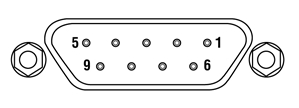
| Connector | DB9F, Left Side |
| Sensor Temperature Control | Thermistor |
| Temperature Range | -10 to 80 °C |
| Analog Outputs | |
| Signal | Amplified Input Signal (Not Corrected) |
| Voltage Range | 0 to 2 V |
| Accuracy | ±3% |
| Bandwidth | Up to 100 kHz, Dependent on Sensor and Settings |
| Connector | SMA, Left Side |
| Digital Outputs | |
| Memory | 8 GB Removable SD Card |
| Connector / Interface | Mini USB / USB 2.0 |
| Power | |
| Battery | Li-Polymer, 3.7 V, 1300 mAh |
| Charger / DC Input | 5 V / 1 A |
| Dimensions and Mounting | |
| Dimensions (L x W x H) | 180 mm x 105 mm x 38 mm (7.09" x 4.13" x 1.50") |
| Weight | < 0.5 kg (< 1.1 lb) |
| Mounting Options | Kickstand; 1/4"-20 Post Thread |
| Operating Temperature | 0 to 40 °C |
| Storage Temperature | -40 to 70 °C |
センサの互換性に関する仕様
| Item # | PM100D | ||
|---|---|---|---|
| Detector Compatibility | Photodiode Sensors: S1xxC Series Photodiodes (Max 5 mA) | Thermal Sensors: S3xxC Series Thermopiles (Max 1 V) | Pyroelectric Sensors: ESxxxC Series Pyros (Max 100 V)a |
| Measurement Ranges | 6 Decades; 50 nA - 5 mA Ranges Selectable in W or A, Sensor Dependent | 4 Decades; 1 mV - 1 V Ranges Selectable in W or V, Sensor Dependent | 4 Decades; 100 mV - 100 V Ranges Selectable in J or V, Sensor Dependent |
| Wavelength Ranges | 200 nm - 1800 nm (Sensor Dependent) | 190 nm - 25 μm (Sensor Dependent) | 185 nm - 25 μm (Sensor Dependent) |
| Power / Energy Ranges | 100 pW - 20 W | 100 μW - 200 W | 10 μJ - 15 J |
| Units | W, dBm, W/cm2, A | W, dBm, W/cm2, V | J, J/cm2, W, W/cm2, V |
| Accuracy | ±0.2% of Full Scale (5 µA - 5 mA) ±0.5% of Full Scale (50 - 500 nA) | ±0.5% of Full Scale (10 mV - 1 V) ±1% of Full Scale (1 mV) | ±0.5% of Full Scale (100 mV - 100 V) |
| Display Resolution | 1 pA / Responsivity Value (A/W) | 1 µV / Responsivity Value (V/W) | 100 µV / Responsivity Value (V/J) |
| Bandwidth | DC - 100 kHz, Dependent on Sensor and Settings | DC - 10 Hz, Dependent on Sensor and Settings | N/A |
| Max Repetition Rate | N/A | N/A | 3 kHz |
| Wavelength Correction | Sensor Dependent; nm (A/W) | Sensor Dependent; nm, (V/W) | Sensor Dependent; nm, (V/J) |
センサーヘッドの詳細な仕様は、フォトダイオードパワーセンサ、サーマルパワーセンサや焦電エネルギーセンサに掲載されています。この他の情報については当社にお問い合わせください。
特長
- センサの情報、日付/時刻、バッテリ状態をヘッダーラインに表示
- ステータスラインでは、警告が表示されます。他には棒グラフと設定可能な左側と右側のサブディスプレイがあり、最大・最小値、あるいはその比が表示されます(数値表示画面のみ)。
- メニュー上部にツールチップテキスト
- 操作が分かり易いメニューソフトボタン
| GUI Overview | ||
トップバーには、センサの情報、日付/時刻とバッテリ寿命が表示されています。 メインウィンドウには、下記の6つの標準ディスプレイの1つが表示されます。ここでは測定値と共に最小値と最大値が表示されています。 メインウィンドウの下には棒グラフがあり、パワーやエネルギの相対的・絶対的変化を表示します。 PM100D のボトムバーには、Dパッドによって制御される8つのメニューが表示されます。 |
| 表示画面の最下部にあるこれらのメニューからは、PM100Dの全ての標準仕様とカスタム仕様の画面にアクセスできます。このサブメニューの上には、これらのメニューのナビゲーションメッセージが表示されます。 パワーとエネルギーレンジ、波長、測定構成、単位、音の調整、測定の画面やシステムメニューは、全てこのボトムメニューからアクセス可能です。 ボトムメニューは、周波数、パワー密度と最大/最小値が表示できるようにカスタム仕様にすることができます。 |
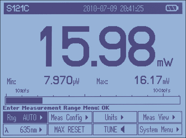
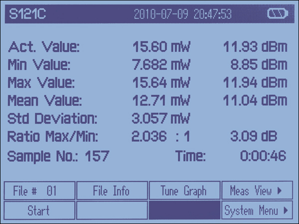
| 数値表示画面(パワーモード) | 統計値表示画面 (パワーモード) | ||
| この画面には、4桁の光パワー値、ズーム機能のある棒グラフ、および構成の設定が可能なサブディスプレイが表示されます。 |
| この画面では、実際のパワーの最小値、最大値、平均値がリニアまたは対数表現で表示され、さらに標準偏差、最大/最小比、サンプリング数、経過時間も表示されます。 |
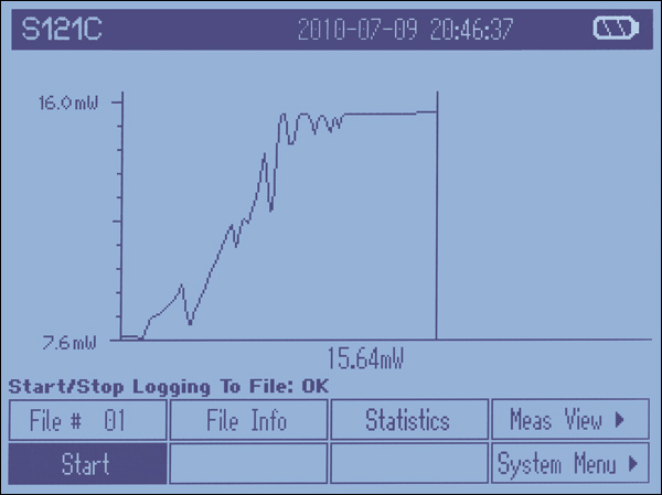
| 傾向グラフ (パワーモード) | 指針表示によるチューニング (パワーモード) | ||
| この画面では、レーザーチューニングやビームアライメント時の変化をグラフで確認できると同時に、絶対値が4桁の数値で表示されます。 |
| この画面では、レーザーチューニング時に、アナログ計器の指針を模した画像と4桁の数値を見る事ができます。リセット可能な最大ホールドインジケータとシフト可能なチューニング音が特別な機能として付いています。 |
| パルス数値表示画面 (エネルギーモード) | パルス統計値表示画面 (エネルギーモード) | ||
| この画面には、4桁の光エネルギ値、ズーム機能のある棒グラフ、および構成の設定が可能なサブディスプレイが表示されます。 |
| この画面では、実際のエネルギーの最小値、最大値、平均値がリニアまたは対数表現で表示され、さらに標準偏差、最大/最小比、サンプリング数、経過時間も表示されます。 |
| パルスチャート (エネルギーモード) | |||
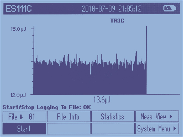
| 傾向グラフ(パワーモード)の場合と同様に、入射ビームパルスの絶対エネルギ値の変化や傾向がグラフで確認できて、4桁の数値でも表示されます。 | ||

この表示画面は、表示する測定作業を選択してカスタム仕様に変更することもできます。表示画面の一部は、お客様によって画面構成も変更できます。例えば指定の期間内での最小/最大値を表示し、チューニング作業中に視覚的にも聴覚的にもピーク値が認識できるように設定することもできます。PM100Dには輝度が調整できる設定があり、完全に消灯することもできます(消灯されていも表示の読み取りは可能)。
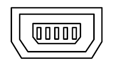
PM100Dセンサ用コネクタD型メス型
|
アナログ出力SMAメス型
0 ... 2 V | コンピュータ接続USBタイプ Mini-B
USBタイプMini-BとType Aの接続ケーブルが付属しています。 |
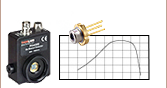
標準フォトダイオードセンサ取付けオプション
当社の標準フォトダイオードセンサはコンパクトな設計で、既存の光学システムへ簡単に組み込むことができます。ポスト、 ケージ、レンズチューブのオプションをはじめとする当社の標準的な光学システムへのマウントが可能です。このページには、数種類の組み込み例が掲載されて います。
標準フォトダイオードセンサは、S120-xxシリーズのファイバーアダプタ全製品に対応します。FC/PC およびSMA アダプタは、右に掲載されています。 FC/APC、SC、LC、ST接続用のアダプタもご用意しています。
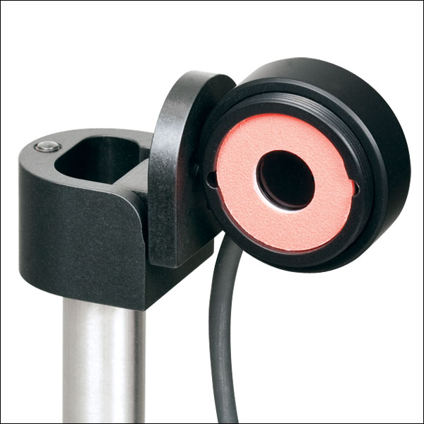
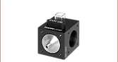
フリップ式マウントにより、定常の光学系のパワー測定を簡単に行うことができます。パワー測定用に、センサをレーザの光路に配置して、システムの通常操作の間は押し下げておくことができます。
右の写真は直角フリップマウントFM90(/M)です。当社では関節式ポストマウントTRB1/Mもご用意しています。固定可能な関節式マウントにより、センサーヘッドを自由に配置できます。

標準フォトダイオードセンサの前面は、SM1ネジで組み込むことができます。SM1ネジにより、25.4 mm(1インチ)レンズチューブシステムや簡単脱着式マウントへ簡単に取り付けることが可能です。
右の写真は、脱着式ポストマウントKB1P(/M)と30mmケージ用簡単脱着式ケージマウントQRC1Aです。どちらのマウントも、SM1ネジにより、センサーヘッドを組み込めます。
注:S12xCシリーズセンサは厚みがあるため、簡単脱着式マウントQRC1AおよびCP44F(下の写真)をケージシステムから完全に取り外すには、ケージシステムの開いた端まで後退させる必要があります。右の写真のようにケージロッドを3本しか使用していない場合、マウントはケージシステムから簡単に取り外し可能です。
当社では、簡単脱着式マウント付き30 mmケージプレートCP44Fもご用意しています。このマウントは磁石によって結合するので、簡単に繰り返し取り付けることができます。
注:QRC1Aと同様に、CP44Fは閉じた状態のケージシステムから取り外すことはできません。
薄型フォトダイオードセンサ取付けオプション
当社の薄型フォトダイオードセンサは、30 mmケージシステムや光学素子が密に配置された自由空間システムをはじめとするスペースの限られた光学装置にもお使いいただける設計となっています。
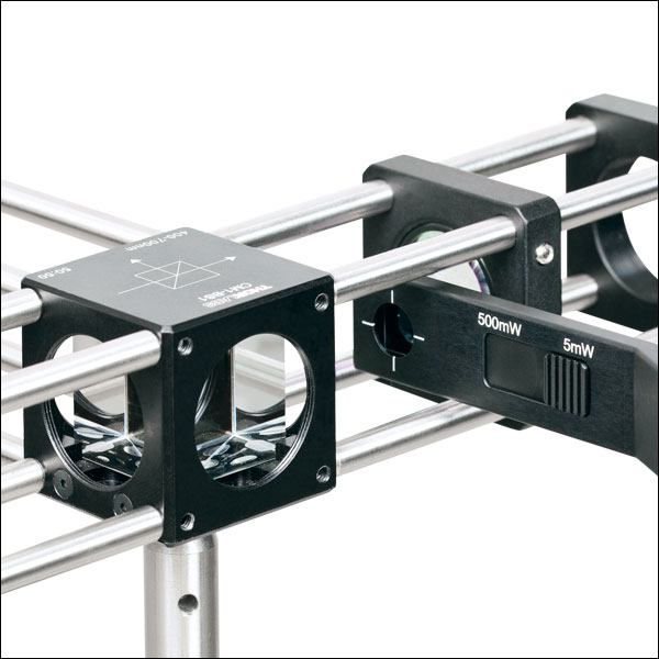
右の写真は、30 mmケージシステムに挿入されたセンサS130Cです。この使用例により、センサをケージへ簡単に組み込むことができます。パワー測定に必要な最低限のスペースしか必要としないことがわかります。
薄型フォトダイオードセンサは関節式マウントTRB1/Mの上にも取り付けることができます。このマウントによって、センサをスペースのない光学装置にも繰り返し挿入することが可能です。測定後、センサを回転させることにより光路から外し、通常操作が可能になります。
小型・薄型フォトダイオードセンサ取付オプション
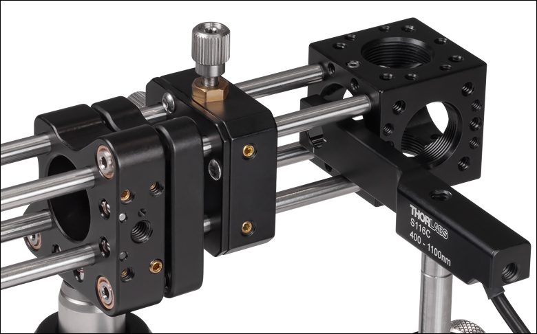
当社の小型の薄型フォトダイオードセンサは、16 mmケージシステムやスロット付きØ12 mm~Ø12.7 mm(Ø1/2インチ)レンズチューブ、そして光学素子が密に配置された自由空間システムをはじめとするスペースの限られた光学装置にお使いいただける設計となっています。
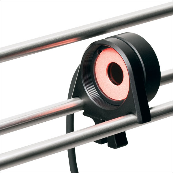
右は16 mmケージシステムに取り付けられたセンサS116Cです。この使用例により、センサをケージへ簡単に組み込むことができます。パワー測定に最低限のスペースしか必要としないことがわかります。
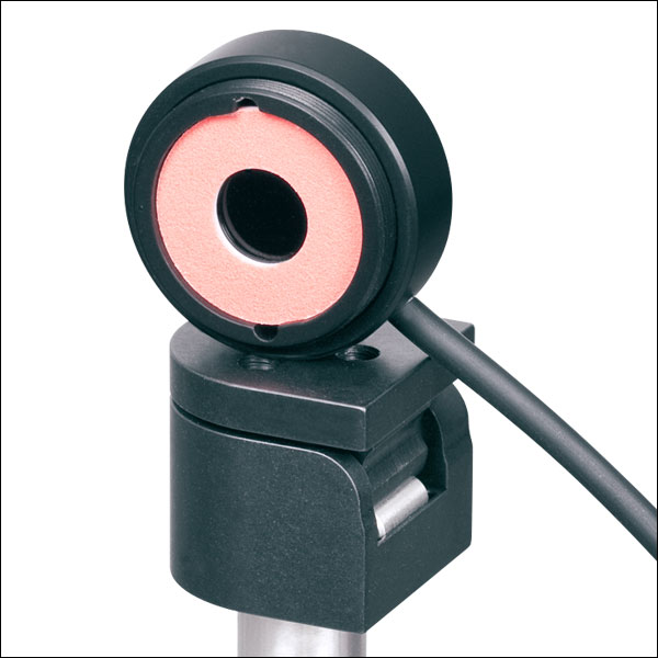
小型の薄型フォトダイオードセンサには、ポスト取付用のM4タップ穴が2つ付いています。右の写真のようにセンサを水平方向に取り付けることができます。もう1つのタップ穴を用いるとセンサを垂直方向に取付可能です。センサは関節式マウントTRB1/Mの上にも取り付けることができます。このマウントによって、センサをスペースのない光学装置にも繰り返し挿入することが可能です。測定後、センサを回転させることにより光路から外し、通常操作が可能になります。
顕微鏡用スライドフォトダイオードセンサ取付オプション
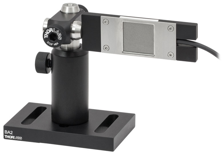
ポストに取り付けたS170C
S170Cは、筐体の側面にあるM4タップ穴を使用してポストに取り付けることができます。

顕微鏡用スライドパワーセンサは、顕微鏡用スライドホルダに直接取り付けられるよう設計されています。76.0 mm x 25.2 mm x 5.0 mmのセンサーヘッドは、標準の顕微鏡用スライドと同じ設置サイズで、多くの標準的な正立および倒立顕微鏡にお使いいただけます。右の写真ではパワーセンサS170Cを裏返して使用しており、筐体の刻印付きの裏面がアライメントに使用できるようになっています。
パワーセンサS170C、S171C、NS170Cにはポスト取り付け用のM4 x 0.7タップ穴も1つ付いています。右の写真ではセンサーヘッドS170Cを水平方向に取り付けるため、2本のØ1/2インチ(Ø12.7 mm)ポストにRA90(/M)を使用しています。
積分球フォトダイオードセンサ取付けオプション

当社の積分球フォトダイオードセンサは、発散ビーム、不均一のビーム、軸から外れたビーム向けの低損失キャビティを備えています。積分球はファイバ終端でのビームが発散する光ファイバ関連の用途に適しています。
右の写真はファイバーアダプタS120-FCを付けた積分球フォトダイオードS140Cと、ファイバ素線アダプタS140-BFAを付けたS140Cです。ファイバ素線アダプタには、取り付けクランプと周辺光からの干渉を少なくする遮光体が付いています。
小型ファイバーフォトダイオードセンサ取付けオプション
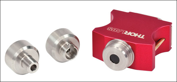
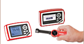
当社の小型ファイバーフォトダイオードは、ポータブル式ファイバ結合用のパワーメータとして適しています。S15xCセンサは様々なファイバ接続に対応します。 PM20-xxアダプタを使って、センサをFC、APC、SMA、ST、SC、LCコネクタに接続することができます。右の写真はFC&SMAコネクターアダプタをつけたS150Cセンサです。
1番右の写真は、センサS150Cが付いたPM100Dのコンソールです。ここではセンサがFC接続でファイバにつながっています。このセットアップは持ち運びが可能であるため、実験や現場でのご使用に適しています。
焦電エネルギーセンサ取付けオプション

当社の焦電エネルギーセンサは、パルス光源の測定に適していて、光源のエネルギーを直接読み取ることができます。センサは、エキシマ、YAGその他ハイパワーレーザの高エネルギーパルス用に設計されています。
各センサには、Ø12 mm~Ø12.7 mm(Ø1/2インチ)ポストに取付けるための絶縁アダプタが付属しています。また、右の写真のように当社の30 mmケージシステムへの取り付けも可能です。
対応するパワーメータ
- コンソール
- アナログパワー&エネルギーメーターコンソールPM100A
- デジタルパワー&エネルギーメーターコンソールPM100D
- 静電容量タッチパネル式パワー&エネルギーメーターコンソールPM400
- 2チャンネルベンチトップ型光パワー&エネルギーメーターコンソール(バージョン4.0以降)PM5020
- パワーメータ
- Bluetooth®方式ワイヤレスハンドヘルド型パワーメータPM160、PM160T、PM160T-HP
- 小型USBパワーメータPM16シリーズ
- 光ファイバパワーメータM60およびPM61(バージョン6.0以降)
- インターフェイス
- PM101シリーズパワーメーターインターフェイス、外部読み出しタイプ(バージョン2.0以降)
- PM102シリーズパワーメーターインターフェイス、外部読み出しタイプ(バージョン2.1以降)
- PM103シリーズパワーメーターインターフェイス、外部読み出しタイプ(バージョン3.0以降)
- USB接続デジタルパワー&エネルギーメーターPM100USB
Optical Power Monitor
このGUIソフトウェアOptical Power Monitorには、パワーの測定、最大8台までのパワーメータの読み取り、およびワイヤレスでのリモート操作といった機能があります。
特定のソフトウェア機能の詳細については、こちらからダウンロードいただけるユーザーマニュアルをご覧ください。
旧世代のPower Meter Softwareについてはこちらのソフトウェアページをご覧ください。
PM101シリーズパワーメータはバージョン2.0以降のみに対応します。PM102シリーズパワーメータはバージョン2.1以降のみに対応します。PM103シリーズパワー&エネルギーメータはバージョン3.0以降のみに対応します。コンソールPM5020はバージョン4.0以降にのみ対応します。
タッチパネル型、ハンドヘルド型、およびUSB接続型光パワーメータ用のGUIソフトウェアOptical Power Monitor
特長
- 最大8台までのパワーメータを同時操作
- リアルタイムでの測定値の記録と解析
- 直感的なアナログ表示とグラフモード
- 設定可能な長時間のデータロギング機能
- サーマル位置&パワーセンサによる位置測定もサポート
- USBおよびBluetooth®接続に対応
Optical Power MonitorのGUIを用いると、USB、RS232またはBluetooth®ワイヤレスa接続により最大8台までのパワーメータのシームレスな制御が可能です。パワーメータ用の最新のソフトウェア、ファームウェア、ドライバ、およびユティリティはこちらからダウンロードできます。
このGUIパッケージには、多チャンネルのデータ測定と解析機能が組み込まれています。インターフェイスは使いやすさを考慮した設計になっています。表示色を最小限にし、輝度も低く抑えているため、レーザ用保護メガネを着用しながらの暗い実験室での使用に適しています。測定データはアナログ針、デジタル数値、線グラフ、あるいは棒グラフでリアルタイムに表示できます。連続したログデータや短時間での測定結果は、後でデータの閲覧や解析を行うために記録することできます。組み込まれている統計モードでは測定データの解析を行い、予め設定された測定周期で新しい測定値を反映させ、連続的に更新を行います。当社のサーマル位置&パワーセンサを用いたビーム位置測定にも対応します。
このソフトウェアパッケージOptical Power MonitorでGUIをインストールすると、すぐにタッチパネル型、ハンドヘルド型、またはUSB接続型のパワーメータの制御にご使用いただけます。対応するパワーメータのファームウェアの更新も可能です。当社のパワー&エネルギーメーターコンソールに使用できる、LabVIEW、Visual C++、Visual C#を用いたプログラム例やドライバが、ソフトウェアと一緒にインストールされます。詳細についてはマニュアルをご覧ください。
なお、このOptical Power Monitor Softwareは、Power Meter Utilities Softwareとは異なるドライバを使用しているのでご注意ください。当社では最新のドライバTLPM.dllのご使用をお勧めします。従来のPower Meter Softwareや以前のドライバPM100D.dllを使用したカスタムソフトウェアを使用したい方のために、2つのバージョンのドライバを簡単に切り替えられるプログラムPower Meter Driver Switcherが付属しています。
a. パワーメータPM160、PM160TおよびPM160T-HPにBluetooth®機能が付いています。
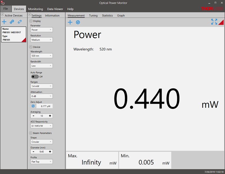
Click to Enlarge
パワー測定モード:最大8台までのパワーメータのセットアップと設定
Click to Enlarge
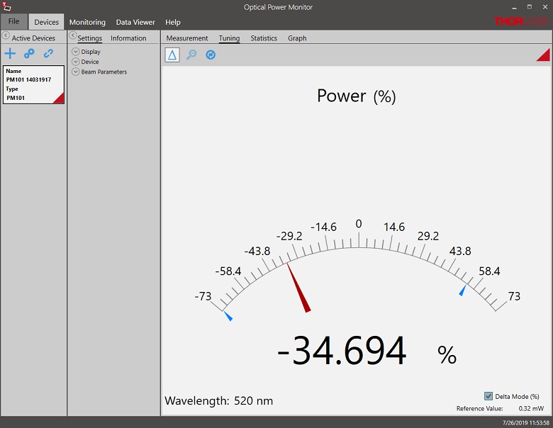
パワーチューニングモード:測定値のアナログ針表示とデジタル数値表示。上図ではデルタモードが有効になっており、測定時間中の変動幅を示しています。
Click to Enlarge
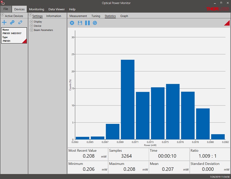
パワー統計モード:予め設定された測定時間における統計量を計算します。上では解析したデータを棒グラフで、計算結果を数値で表示しています。
Click to Enlarge
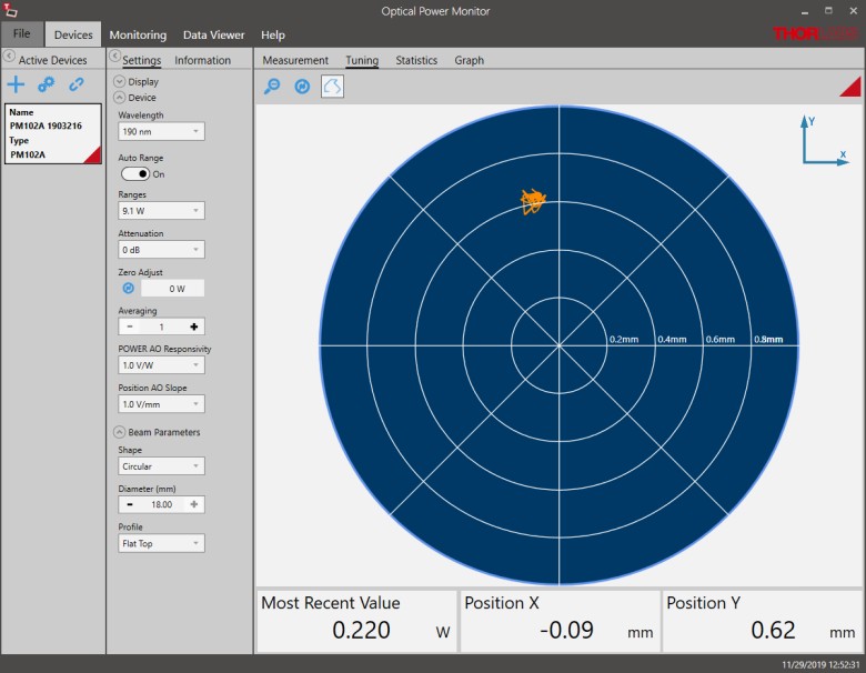
位置チューニングモード:こちらのチューニングモードはサーマル位置&パワーセンサでのビームアライメントにご使用いただけます。

Click to Enlarge
位置統計モード:統計モードではサーマル位置&パワーセンサの統計情報も表示します。
Click to Enlarge
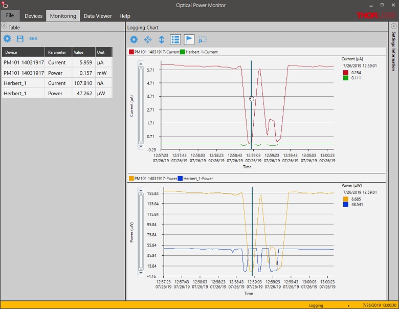
データロギング:長時間測定と最大8台までのパワーメータの同時記録が可能です。データは後処理により.csv形式で保存されますが、測定結果はリアルタイムでグラフ表示されます。

Click to Enlarge
ワイヤレスパワーメータPM160とiPad mini(付属していません)。PM160はApple社のモバイルデバイスを使ってリモート操作が可能です。
こちらでは当社のパワーセンサおよびエネルギーセンサのラインナップをご紹介しています。対応するパワーメーターコンソールとインターフェイスについては右下の表をご覧ください。
下記のパワーセンサおよびエネルギーセンサのラインナップのほかに、当社ではフォトダイオードまたはサーマルセンサのどちらかを内蔵するオールインワン型のワイヤレス機能付きパワーメータや小型USBパワーメータ、およびコンソール、センサーヘッド、ポスト取付け用のアクセサリを含むパワーメーターキットもご用意しております。
当社では4種類のセンサをご用意しております:
- フォトダイオードセンサ: フォトダイオードセンサは感度が波長に依存するので、単色光源もしくは単色に近い光源のパワー測定用に設計されています。このセンサから出力される電流は、入射光パワーと波長によって決まります。この電流はトランスインピーダンスアンプにより、入力電流に比例した電圧を出力します。
- サーマルセンサ: サーモパイルセンサは、広い波長範囲で比較的平坦な応答特性を持つ材料から作られているので、LEDやSLDなどの広帯域光源のパワー測定に適しています。このセンサは、入射光パワーに比例した電圧を出力します。
- サーマル位置&パワーセンサ: これらのセンサでは4つのサーモパイルセンサが正方形の4象限に配置されています。ユニットは各象限からの出力電圧を比較してビームの位置を算出します。
- 焦電エネルギーセンサ: 焦電センサは焦電効果を通じて出力電圧を発生しパルス光源の測定に適しています(ディテクタの時定数によって繰返し周波数は制限されます)。このセンサは、入力パルスエネルギに比例したピーク電圧を出力します。
| Console Compatibility | ||||||||
|---|---|---|---|---|---|---|---|---|
| Console Item # | PM100A | PM100D | PM400 | PM5020 | PM101 Series | PM102 Series | PM103 Series | PM100USB |
| Photodiode Power |  | | | | | - | | |
| Thermal Power | | | | | | | - | |
| Thermal Position | - | - | | | - | | - | - |
| Pyroelectric Energy | - | a | a | | - | - | | a |
パワー&エネルギーセンサのセレクションガイド
当社のパワー&エネルギーセンサの仕様を比較する際には、2種類の選択をします。下の表(展開できます)では、当社のセンサを種類別に分類して(フォトダイオード、サーマル、焦電)、主な仕様を記載しています。
またその下のセレクションガイドのグラフでは、当社のフォトダイオードならびにサーマルパワーセンサの全ラインナップを波長範囲(左)そしてパワー範囲(右)で比較できるようになっています。枠内には型番とセンサの仕様の範囲が記載されています。グラフにより、特定の波長範囲またはパワー範囲に適したセンサーヘッドが特定しやすくなっております。
| Photodiode Power Sensors |
|---|


| Thermal Power Sensors |
|---|


| Thermal Position & Power Sensors |
|---|

| Pyroelectric Energy Sensors |
|---|


センサのラインナップ
(波長範囲)
センサのラインナップ
(パワー範囲)
| Posted Comments: | |
Lin Zhou
(posted 2024-06-14 13:38:46.49) I am using different range of PM100D to record output voltages and it seems the responsivities of different ranges are different. For example, when I'm detecting the same light , working in range 960nw gives me a voltage of 1.8V while woring in range 9600nw giving 0.24V. This relationship doesn't seem clear and I haven't seen anything about this relationship in the PM100D documents. hchow
(posted 2024-07-18 08:17:06.0) Dear Mr. Zhou, thank you for your feedback.
Your question is multi-faceted and too complex for me to give you a proper response here. I will personally reach out to you to provide a comprehensive solution. Thank you. Won-il Lee
(posted 2024-04-30 13:38:52.207) Can I buy only the power meter charger separately? jjadvani
(posted 2024-04-30 03:17:49.0) Dear Won, thank you for contacting Thorlabs. Yes, you can purchase power supply separately. I will contact you directly to provide information on how you can purchase a power supply. jjadvani
(posted 2024-04-30 03:17:49.0) Dear Won, thank you for contacting Thorlabs. Yes, you can purchase power supply separately. I will contact you directly to provide information on how you can purchase a power supply. user
(posted 2024-04-04 09:59:36.527) The battery for my PM100D does not hold charge anymore. Rather than buying a new device, can I replace just the battery? If so, how do I go about that? hchow
(posted 2024-04-04 10:26:34.0) Dear User, thank you for your feedback. If your PM100D's battery is faulty or not chargning or does not hold a charge any longer, we highly recommend you sending in your device for a battery repair/exchange. Thank you. user
(posted 2024-02-05 07:47:19.54) I use PM100D and an S122C head to measure light intensity spectra at the monochromator output. The system is controlled by a program written in LabView. The light intensity is modulated by the chopper in the range of 10Hz -300Hz. When I work in auto range mode and the light intensity increases monotonically, at some point the measured light intensity decreases. This appears when the measured value is close to the maximum value of the range. I did an experiment at one wavelength W=950nm. When I set the range to 1.5mW I got an optical power of 0.253 mW. After changing to auto range I received the same P=0.253 mW. When I set the ranhe to150 mW I got 109.5 uW, after changing to auto range the same 109.5 uW. I set the Range to 13 uW and received HIGH, and after changing to auto range it was 109.5 uW. Why doesn't the meter switch to a higher range? Thank you. dpossin
(posted 2024-02-07 08:33:40.0) Dear customer,
Thank you for your feedback. I´ll reach out to you in order to provide assistance. Genshiro Sunagawa
(posted 2023-12-30 15:59:38.75) I am using PM100D + S150C to detect the light from LED M385F1. When I try to set the wavelength of PM100D to 380 nm, it says, "The adjusted wavelength is outside the sensors wavelength range". Indeed, the sensor info page displays that S150C's wavelength range is 400nm-1100nm, which does not match the spec of S150C. How can I set the wavelength to below 400nm? Thank you. dpossin
(posted 2024-01-02 09:17:07.0) Dear Genshiro,
Thank you for your feedback. This sounds like a malfunction since the sensor is specified to be sensitive down to 350nm. I am reaching out to you in order to provide more detailed assistance. 敏洁 李
(posted 2023-12-30 12:00:44.03) 充电时,充电接口位置有烧糊的味道,且电量显示位置显示箭头,这是什么原因导致的?应该怎么维修处理? hkarpenko
(posted 2024-01-03 06:22:53.0) Dear customer,
thank you for your feedback. It seems that the console is in need of repair. Thus we will directly contact you to guide you through our RMA process. user
(posted 2023-12-27 18:48:14.04) Hi, I use PM100D and S121C to measure laser power at around 80 uW. I use OPM software to control and record data. The recording frequency is around 200 datas per second. BUT the data oscillates up and down at around 100Hz over a 3uW range. Is there an explanation? dpossin
(posted 2024-01-02 09:45:57.0) Dear customer,
Thank you for your feedback. I reach out to you in order to provide assistance. Chia-Lun Tsai
(posted 2023-12-21 18:02:54.823) We have got voltage values, and we want to chane voltage to power. Is there a table for voltage to power? dpossin
(posted 2023-12-27 08:00:40.0) Dear Chia-Lun,
Thank you for your inquiry. I reach out to you directly in order to clarify your questions. Peng Zhao
(posted 2023-12-06 09:57:40.94) Hi,
i have PM100D power meter and S130C detector,
both seems have a problem, PM100D always display 0 and zero! warning, S130C detector can't be recognized by the power meter.
can you fix them?
please give a RMA number
thank you hkarpenko
(posted 2023-12-07 10:27:45.0) Dear customer,
thank you for your feedback. These errors indicate, that either the console or the sensor are in need of a repair. I will contact you directly to discuss this further with you in detail. Sam Chen
(posted 2023-10-10 11:19:21.28) When I use PM100D&S150C to detect the LED power of nW level, the measurement View is set to Numeric, but the display only shows one digit after the decimal point. like 0.7nW. How do I set it to display more valid digits at the Numeric view? jweimar
(posted 2023-10-16 07:07:02.0) Thank you for your feedback! Unfortunately, the 4 digits of PM100D display are not configurable. The highest resolution is 100pW. If you need a higher resolution, you can connect the device to your computer and use the “OPM” Software or use the statistics screen in the device. Jean-Jacques HONORINE
(posted 2023-10-02 09:22:23.07) Dear,
My OS: Windows 2020.
My Labviews version: Lab 2014.
dfu file: PM100D_V2.8.1.dfu
I can't install "PM100D_V2.8.1.dfu", it's normal?
Message: No devices found. Verify if device is connected or if you select the right.dfu file. GBoedecker
(posted 2023-10-05 06:20:38.0) Thank you for your feedback! Please check the current firmware version. If you already have version 2.8.1, you can get this error message. GBoedecker
(posted 2023-10-05 10:32:57.0) Choose "Enable" on the console in System Menu\Console Settings\Firmware Update\ to enable the firmware update. user
(posted 2023-08-21 01:18:16.437) Where can i find the driver of this instrument?
I have downloaded the software given above, but its not working.
I would be extremely grateful if you could provide me a direct link of the driver . I have to connect it to LabView program and do my project!
Thank you! hkarpenko
(posted 2023-08-21 11:18:55.0) Dear customer,
thank you for your feedback. If you are looking for the software of the PM320E, you might have downloaded the wrong software. I will contact you directly and share the correct software with you. Ben Sauer
(posted 2023-06-01 13:33:42.077) We have several PM100's in out lab. They have a common failure mode which could be improved by a design change. The problem is that the d-sub 9 connector for the sensor is a surface mount connector. When someone drops the meter the sensor connector tends to break the SMT bonds to the main circuit board. Sometimes this is repairable and sometimes it isn't. In your next design iteration you should change this connector to a through hole one, which would be much more robust.
Do you sell the main pcb for this as a replacement part? It's model number is M0094-222-800. hchow
(posted 2023-06-01 11:20:45.0) Dear Ben, thank you for your feedback. We do take interest in what our customers have to say about our products. And any feedback you can provide us is valuable. As for the second part of your question, I will personally reach out to you to provide a solution. Thank you. wang jing
(posted 2023-05-22 18:51:23.067) 请问功率计如果想要测试一个波段范围内的平均功率应该怎么设置?可以测多个波长的激光平均功率吗? hchow
(posted 2023-05-24 05:36:57.0) Dear Wang Jing, thank you for your feedback. If you would like to measure the optical power of multiple wavelengths, you would have to set the wavelength setting on the PM100D each time to the preferred wavelength you want to measure. The PM100D is not able to measure the optical power from multiple wavelengths at a time. I will personally reach out to you to provide more information. Thank you. Taeho Woo
(posted 2023-03-22 22:55:07.36) Hi
Would it be possible for me to ask a question?
I was wondering if you could provide me with some information about the temperature levels that the equipment recognizes when it is subjected to different power inputs, specifically 1mW, 2mW, and 3mW. Additionally, would it be possible for me to request a graph that shows the relationship between temperature and power?
I would greatly appreciate any assistance you can offer. Thank you very much. dpossin
(posted 2023-03-28 05:35:38.0) Dear Taeho Woo,
Thank you for your feedback. I am reaching out to you directly to discuss this in more detail. Carlo Ferrari
(posted 2022-11-27 23:23:11.867) Hello, I would like to purchase a replacement power cable for this device. I wasn't able to find it anywhere on the product page or the site.
Can you send me a quote, pleae.
Best regards,
Carlo fmortaheb
(posted 2022-11-28 04:47:14.0) Thank you very much for contacting Thorlabs! We will reach out to you directly and provide you with a quote. Karl Ahrendsen
(posted 2022-10-05 11:44:14.31) Where can I purchase a replacement power cable for this device? I wasn't able to find it anywhere on the product page or the site. fmortaheb
(posted 2022-10-06 05:24:27.0) Thank you very much for contacting us. We will contact you directly to provide you with a quote for the power supply. Igor Musevic
(posted 2022-09-20 12:34:34.29) Hello,
We have PM100D Power meter with S121C, S120C and S470C sensors. We would like to measure the single pulse energy from a 120 fs tunable laser ORIGAMI XP. The repetition rate of this laser can be adjusted from 1 Hz up to 100 kHz. The idea is to measure the average power and divide it by the rate of pulses.
In the manual, there is little information on the frequency range of PM100D. It is only mentioned that it can measure average power of pulsed lasers up to 100 kHz.
Could you please advise us on the optimum repetition rates of our laser to best suit frequency range of PM100D.
What setting of PM100D should be used with that selected repetition rate?
Thank
You
Igor Musevic, Head of the Lab. hkarpenko
(posted 2022-09-22 05:09:24.0) Dear Igor,
thank you very much for your feedback. For these short pulses it´s better to use the thermal based sensor instead of the photodiode one.
I will contact you directly to discuss this case further with you. Laurent Mercadier
(posted 2022-09-09 08:39:37.977) Dear Thorlabs,
I am regularly using a PM100D for laser power measurement. While it works well, I would like to suggest an improvement:
Changing the role of the wavelength button to the role of zeroing.
The reason is that when measuring a laser power, the wavelength is set and there is no need for a convenience button, however we often need to calibrate the detector to zero, especially with low powers. In statistics mode, the only way to do it is to break from statistics to numeric, then navigate another menu to finally be able to press zero. Then, we need to navigate back to statistics, which is tedious and time consuming.
Would it be possible to consider this for a firmware update and exchange the role of the wavelength button to zeroing button?
Thanks in advance,
Dr. Laurent Mercadier fmortaheb
(posted 2022-09-12 10:38:31.0) Thank you very much for your feedback. We don't have any plan to modify the front panel in the near future, but we will consider your suggestions. Concerning the zeroing, it should be possible to do it without switching between the screens. I'll reach out to you directly to discuss it further. Davide Michele Stefano Marcolongo
(posted 2022-05-12 15:16:21.29) Recently, I used a PM100D Console equipped with a S120VC sensor to try the measure of output power of an old short-arc Xe lamp (150 W nominal electrical power) and of some commercial indoor light white LED sources. The console+sensor are not my property, but I found that all the measured sources have an emission output extremely shifted into the UV region and emit quite no power in long visible wavelenght range (red). The same was found with a red LED commercial pointer. Should I consider the instrument is out of calibration?
Thanks in advance
Dr. Davide M.S. Marcolongo mdiekmann
(posted 2022-05-17 03:05:51.0) Thank you for contacting us! We will email you directly to troubleshoot this application. Possible issues in this case could be setting the right measurement wavelength given the broad spectrum of the light sources and the angle of incidence. If the unit has not been calibrated recently, that could also cause incorrect readings. Xu Yan
(posted 2022-04-20 02:07:18.4) Hello I'm having Error 0x000000B9 "Timeout during SD-card communication". There is any possible solution to this? fmortaheb
(posted 2022-04-25 12:13:57.0) Dear Xu Yan, Thank you very much for your feedback. I'll contact you directly for troubleshooting. 李 彥澄
(posted 2022-03-01 02:50:35.907) when I used c# to get the laser(senter wavelength :1024nm)power by PM100D,c# may get wrong power value.especially after I use this driver:(https://www.newport.com/p/8742) 8742motion controller to move pezio mirrors,the mirrors move every 0.1 second,mirrors moving will chenge the power of laser.after moving,c# usually get wrong power from PM100D,for example,I saw the PM100D show power is 100mW,but c# get 50mW.
What can I do to get the currect power by c#?whith is the real power?power witch PM100D showed or power witch readed by c#? is it possible to let power showed by PM100D and power readed by c# alway be the same,at any time?
thank for you reply. wskopalik
(posted 2022-03-02 03:55:15.0) Thank you for your feedback!
The power values shown on the PM100D and in C# are the same if the same settings are used. The most important setting is usually the wavelength. You can use the “setWavelength” function to adjust the wavelength in C#. If you e.g. use an attenuation setting or a particular power range on the PM100D, these settings would need to be made in C# as well to get the same results.
I will contact you directly to provide further assistance. Carlos Reyes
(posted 2022-02-07 12:24:34.873) Hello,
I have recently bought a PM100D. I downloaded the most recent sw and I was able to connect to it using the application.
When trying to control the power meter using LabView the Visa Driver is not recognized. The device appears in the device monitor but not in Ni-Max. I tried installing the legacy versions and still was unable to make a successful connection. I'm currently using LabView 21.0. Could you reach for further support? wskopalik
(posted 2022-02-10 03:16:25.0) Thank you for your feedback!
There are two different drivers available for the PM100D. The older PM100D driver was using the NI-VISA interface. The new TLPM driver is no longer using this interface. They can however both be used in LabView by using the provided VIs.
You can use the “Power Meter Driver Switcher” tool which is installed with the “Optical Power Monitor” software to switch between the two drivers. This can e.g. be helpful if you already have an application which is using the older driver.
I will contact you directly to provide further assistance. Patrick Schmidt
(posted 2022-01-04 18:29:34.687) I have a PM100D and S175C for power measurement. I would like to collect and log data in Python on a windows PC, do you have a clean way to do this? Thanks. GBoedecker
(posted 2022-01-07 10:53:33.0) Dear Patrick, thank you for your inquiry. We provide a Python wrapper for the instrument driver. After installation of the software, you find the wrapper, the manual and a Python example in the folders documented in chapter 9 of the software manual.
https://www.thorlabs.com/software/MUC/OPM/v3.0/TL_OPM_V3.0_web-secured.pdf Borislav Glebov
(posted 2021-10-21 11:53:34.85) Hello. A few years ago I used the PM100-D device and a very old version of the Optical Power Monitor. The software had a feature - the number of recorded points is no more than 3000. Therefore, at high time resolution, it could record data for no more than 30 seconds. Now we can use Optical Power Monitor v3.1 for PM100-D, and there is no parameter "number of recorded points" in it, but the "resolution" tab remains. Does this mean that the limit on the number of recorded points at any resolution has now been removed for PM100-D and is limited only by the free space of the PC RAM? In other words, is it now possible to record data from PM100-D for several hours with a resolution of 0.01 seconds? dpossin
(posted 2021-10-27 12:18:51.0) Dear Borislav,
Thank you for your feedback. Its right, that there is no limitation regarding the maximum number of data points. However the data acquisition rate is fixed to 300ms and can´t be changed. The values are then saved to the included SD card which allows recording duration of several hours. I am reaching out to you in order to discuss this matter more detailed. dpossin
(posted 2021-10-27 12:18:51.0) Dear Borislav,
Thank you for your feedback. Its right, that there is no limitation regarding the maximum number of data points. However the data acquisition rate is fixed to 300ms and can´t be changed. The values are then saved to the included SD card which allows recording duration of several hours. I am reaching out to you in order to discuss this matter more detailed. Mike Sym
(posted 2021-10-20 08:15:14.197) Hello, regarding the measurement range, the manual states that the measurement will be precise within -10% to 110% of the selected range. If the range is set to eg. 10mW, this means that the values are precise within the [9,11] mW range, right? Can the measurement range be set manually in some arbitrary value within the range of the sensor?
To better explain my question, I am monitoring the power-meter output from the analog interface, however when the power reaches ~12mW, the range is increased by a factor of "10" and the output get very noisy (as it lies now close to the "0" level). So, I would like to set the range at about 20mW.
Thanks! dpossin
(posted 2021-10-26 03:57:34.0) Dear Mike,
Thank you for your feedback. The autoranging can be disabled but the range limits can´t be changed as they are determined by the current measurement bridge on the hardware. I am reaching out to you to provide further information. Mike Sym
(posted 2021-10-15 14:51:22.13) Hello, is there a way to control the power meter or extract the CSV files using a Linux distribution? That would be really helpful. dpossin
(posted 2021-10-25 10:22:55.0) Dear Mike,
Thank you for your feedback. Well we also provide a Linux (Ubuntu) version of our optical power monitor software on request. I am reaching out in order to provide it to you. Vad Kir
(posted 2021-06-30 05:13:52.687) Hello I'm having Error 0x000000BE "Invalid directory name". There is any possible solution to this? MKiess
(posted 2021-07-05 08:31:25.0) Dear Vad, Thank you very much for reporting this issue. I will contact you directly for troubleshooting. J Schmoll
(posted 2021-06-10 14:32:34.813) I tried testing the PM100D using the LabVIEW examples supplied with the Optical Power Monitor software. The LabVIEW VIs are in the TLPM.LLB file. I tried to run the 32-bit examples. However, the example VI "Measure Power Sample.vi" was apparently saved in LabVIEW version 2019. I was trying to run the VIs in LabVIEW 2017. All of the other VIs in the library were apparently saved with earlier versions of LabVIEW, and I could open them without problems.
I have used other Thor optical power meters in LabVIEW, so I wrote a simple test program using the same VI calls that worked for the other power meters. The code failed in the initialization step. The PM100D had firmware version 1.3.1. I updated it to 2.7.0, and now my LabVIEW code runs without error. MKiess
(posted 2021-06-14 09:56:12.0) Dear Mr. Schmoll, Thank you very much for this feedback. The version 1.3.1 is a quite old firmware version, with which there can be complications with the newer drivers. An update to the latest firmware and software version is always a recommendation here. Milan Delor
(posted 2021-03-11 19:01:51.41) Hello, are your power meter consoles (PM100D or PM400) compatible with power sensors from other manufacturers, such as Coherent? Alternatively, do you make custom power sensors? We need a 40 - 50 W max power sensor which is unfortunately not available with Thorlabs. soswald
(posted 2021-03-16 10:55:31.0) Dear Milan,
thank you for your feedback. Our power meter consoles are not compatible with third-party sensors.
For high powers in the 40-50 W regime we offer thermal sensors such as S425C-L or S322C. Since you prefer not to be contacted, please reach out to your local tech support team directly to discuss your application in more detail. MKiess
(posted 2020-12-14 06:34:06.0) Thank you for your feedback. Please check that you have the latest firmware installed on the PM100D. We have made a few changes regarding the SD card. You can find the firmware download at the link below:
https://www.thorlabs.de/software_pages/ViewSoftwarePage.cfm?Code=OPM user
(posted 2020-11-18 12:44:15.56) Is there a way to reset all settings/memory to the factory default? MKiess
(posted 2020-11-19 09:58:02.0) Thank you very much for your inquiry. Depending on the sensor used, the PM100D can be reset to the default settings for the respective sensors (thermopile, photodiodes, pyroelectric). This can be done under 'System Menu \ Measurement Settings' for the corresponding sensor. Alexander Kuznetsov
(posted 2020-06-30 10:25:33.08) I have a question about the drivers TLPM_32 and PM100D_32.
In our lab, we have a custom software to communicate with several PM100D remotely (e.g. the PM100D is connected to one PC and a user communicates with it from another PC). Such remote communication using PM100D_32.dll via NI-Visa Server works fine. However, devices configured to use the TLPM_32.dll driver are not "visible". Switching the driver to PM100D_32.dll solves it. However I would like to know, how would one achieve the remote communication with the device using TLPM_32.dll?
Thank you in advance. dpossin
(posted 2020-07-03 03:53:47.0) Dear Alexander,
Thank you for your feedback. We switched our software from the NI-VISA based driver PM100D.dll to the more robust driver architecture TLPM.dll. However if you need the old driver for your application we provide a tool called power meter driver switcher is installed together with the power meter software. Please find instructions how to change between the drivers in section 7 here: https://www.thorlabs.com/software/MUC/OPM/v2.2/TL_OPM_V2.2_web-secured.pdf. Also the commands are different compared to the old NI-VISA based driver. Instructions on programming the TLPM driver can be found here: C:\Program Files (x86)\IVI Foundation\VISA\WinNT\TLPM\Manual. I am reaching out to you in order to provide further support. BINBIN ZHAO
(posted 2020-05-04 01:29:02.887) Is there any example of MATLAB code used to control the PM100D and record the power automatically? MKiess
(posted 2020-05-05 10:38:32.0) This is an response from Michael of Thorlabs. Thank you very much for your inquiry. I have contacted you directly to provide further information. Yangyang Liu
(posted 2020-01-09 15:12:26.583) I am using PM100D. Recently, I want to update the firmware. And I connect the PM100D to computer by the monitor software. When I use the software to update the firmware there is always a warning that "user abort the download operation" but I do nothing. Hope for your answer. Thanks. Regards, Yangyang Liu. nreusch
(posted 2020-01-10 08:52:49.0) This is a response from Nicola at Thorlabs. Thank you for contacting us. Could you please check whether you enabled the firmware download mode on the PM100D console (System Menu -->
Console Settings -->
Firmware Upload -->
Enabled) before trying to install the new firmware with the DFU wizard? A local Tech Support representative will contact you for further troubleshooting. Junji Okamoto
(posted 2019-12-12 09:13:59.773) I would like to know about "analog output" of PM100D.
Q1, Is the output voltage from analog output "DC" voltage? (Is its wave shape flat?)
Q2, Is the output voltage basically go from 0V to +2.0V? (In a Manual, from -0.3V to +2.3V) wskopalik
(posted 2019-12-12 11:13:29.0) This is a response from Wolfgang at Thorlabs. Thank you for your inquiry!
The voltage signal at the analog output is the amplified photo-diode current or the amplified thermal or pyroelectric sensor voltage. So the voltage will change corresponding to the power of the incident light. If the incident light is CW, the signal will be a flat voltage signal. If the incident light is however modulated or pulsed, the signal will be modulated or pulsed as well.
The range of 0V to 2V is the range in which you will get reliable measurement results. If e.g. the amplifier or the sensor are saturated, it is however possible that you get voltages in the range of -0.3V up to +2.3V. So the devices attached to the analog output should be able to handle voltages in this range without any damage.
I will contact you directly to provide further assistance. A. Devine
(posted 2019-12-02 15:49:34.81) While polling a thermopile sensor over USB with the PM100D (using the LabVIEW drivers), occasionally NaN is returned instead of an actual power reading value. This seems to happen most frequently when readings are taken too close together. I have solved the problem by adding a 20 second delay between readings, but this seems too large. I do not experience the same behavior with the PM200 or newer power meters. I would appreciate any insight as to why the meter is returning NaN so that I can work on a more elegant solution.
Thanks,
AD MKiess
(posted 2019-12-05 09:32:58.0) This is an response from Michael of Thorlabs. Thank you very much for your inquiry. I have contacted you directly to discuss the specifications and measurement procedure of your light source, as well as the programming to find a solution together. Ian Roberts
(posted 2019-10-29 19:32:01.613) Using the SCPI commands in the manual I can communicate with the PM100D over USB to read the instantaneous power, which works well. However, I want to record data at a high rate (ideally every millisecond) which is too fast for serially polling the device using the MEAS power command.
As the device can make measurements very rapidly and store the data to a CSV file, is it possible to read this data / transfer the file (once measurement is finished) over USB using SCPI commands? Or some other way (e.g. mounting the storage as a device the computer can access?)
I appreciate Thorlabs offer a driver package / GUI but having to install separate software is highly unattractive (/ not even possible in some situations due to lack of admin rights). Thanks. MKiess
(posted 2019-10-31 08:55:39.0) This is a response from Michael at Thorlabs. Thank you very much for the inquiry. The limitation here is due to the data transfer rate of USB. However, you can use the analog output, which has a bandwidth of up to 100kHz. I contacted you directly to find a suitable solution for your application together. DAVID KINGHORN
(posted 2019-06-07 20:44:24.12) What is the part number for the AC Battery Charger for the PM100D Console? MKiess
(posted 2019-06-12 05:05:45.0) This is a response from Michael at Thorlabs. Thank you very much for the inquiry. The AC adapter for charging the system battery is not a standard Thorlabs product and therefore not available on our website. But of course it is possible to get a replacement from us. I will contact you directly to discuss further steps. Samuel Gyger
(posted 2019-05-31 05:55:41.643) We have the devices for a long time now and it seems the battery becomes bad (S/N P0000874) and (S/N PM001464)
Is it possible to exchange the battery by ourselves. Are you selling replacement batteries? Or should we buy one online?
Regards,
Samuel Gyger dpossin
(posted 2019-06-06 09:56:01.0) Thank you for your feedback. It is not intended to change the battery by our customers but we offer to change the battery inhouse as a service. I will reach out to you directly in order to discuss the details. Eneko Lopez
(posted 2019-03-21 07:29:41.42) we have a PM100D console with a S121C sensor. Is there anyway to acquire data with matlab software? It would be very helpful for us.
Thank you! swick
(posted 2019-03-29 04:40:11.0) This is a response from Sebastian at Thorlabs. Thank you for the inquiry. It is possible to remote control our power meter via Matlab. I contacted you directly to provide assistance. Cao Duc
(posted 2019-03-21 10:37:56.82) we recently received the PM100D console and a pyroelectric energy sensor ES120C with accessories. I tried to connect the sensor and the console by the insulator, post, and post holder but there was no signal at the display of the console, although it recognized the sensor, i turned trigger number down to 3%, then when i touched the console or the sensor it started having some noise, but the noise also stopped when i stopped touching. I tried again with my laser source, there was signal again. Can you give me some advice; or the specific connecting or setting guide of those devices will be very helpful with me. Thanks you! swick
(posted 2019-03-29 04:57:09.0) This is a response from Sebastian at Thorlabs. Thank you for the inquiry.
The function principle for these sensors is different compared to Thermopiles or Photodiodes. Pyroelectric sensors (ES-Series) do only generate a signal when an optical pulse is detected.
The pulse energy needs to be larger than the threshold which is defined via trigger level thus when setting trigger level to very low values you can observe noise. The measurement value will be updated with each incoming pulse and when no pulses appear the measurement display will be held on the last measured value.
I contacted you directly to provide further assistance. jagroopastro5
(posted 2019-01-05 22:00:31.453) sir,
recently i have purchased the PM100D with S130VC sensor module. i have measured the He Ne laser power with it and same time corresponding current in current mode. when i compare with the response curve of the sensor, it is showing high responsivity ( 0.4 approx against 0.36 specified value and it varying non linearly with power? why it is so?
sir, do a high frequency oscillator device placed near sensor hear will affect the measurement of device? wskopalik
(posted 2019-01-08 07:30:13.0) This is a response from Wolfgang at Thorlabs. Thank you very much for your feedback!
There are different possible reasons for this, e.g. the coupling of the laser in the sensor, incorrect settings on the power meter or also tolerances in the power of the laser itself.
I will contact you directly so we can look into the details and find an explanation for these results. krzysztof.anders
(posted 2018-12-14 21:06:32.34) After deleting all files and directories on SD card I'm unable to write statistics file - every time I get Error 0x000000BE "Invalid directory name". I was trying also to format SD card (FAT32) and putting there PM100LOG directory - still the same problem nreusch
(posted 2018-12-20 07:28:56.0) This is a response from Nicola at Thorlabs. Thank you very much for reporting this issue. I will contact you directly for troubleshooting. jlm
(posted 2018-10-01 14:17:08.03) Hey
I am trying to interface to your console PM100D with a c++ program written in QT.
In the document https://www.thorlabs.com/software/MUC/OPM/v1.1/TL_OPM_V1.1_web-secured.pdf you state that I should find a header file at;
“C:\Program Files (x86)\IVI Foundation\VISA\WinNT\include\TLPM.h”
Unfortunately I cannot locate such a file. I tried to repair the installation, but that did not mend the issue.
Can you help me? nreusch
(posted 2018-10-04 04:58:17.0) This is a response from Nicola at Thorlabs. Thank you for your inquiry. Yes, you are right the header file should be stored there. As this does not seem to be the case, I will send you the file via email. kay.schaarschmidt
(posted 2018-08-08 15:23:22.83) Hi,
we are trzing to use the Thorlabs software and labview to read out data from a PM100D. It worked for occasionally but suddenly an error kept occuring
Error -1073807345 occurred at PM100D Initialize.vi
Neither our self-made labview program, nor the Thorlabs software is currently working anymore.
Help appreciated. nreusch
(posted 2018-08-09 10:59:53.0) This is a response from Nicola at Thorlabs. Thank you for your inquiry! This seems to be a connection issue. I recommend to start troubleshooting this by using the Thorlabs software. Which version is installed on your PC? I will contact you directly to provide further assistance. user
(posted 2018-06-20 13:03:01.267) The cable on the wand is quite annoying. Will you ever offer a wireless sensor? YLohia
(posted 2018-06-20 04:26:31.0) We offer wireless sensors here: https://www.thorlabs.com/newgrouppage9.cfm?objectgroup_id=7233 hi243
(posted 2018-06-09 19:50:50.447) Hi,
I have the PL450B blue laser diode (450nm, 80mW) and I wish to measure the optical power coming out of this laser diode when it is pulsed at 30mW. The laser beam will be obstructed by a tuning fork element I am using, so the final optical power that I need to detect is around 1mW. My lab already has the PM100D console, so I just need help from you on deciding on a suitable power sensor/photo diode which can help me measure optical powers in the range 1mW-80mW (@450nm). Thanks mvonsivers
(posted 2018-06-13 09:03:15.0) This is a response from Moritz at Thorlabs. Thank you for your inquiry. The S121C would be suitable to measure powers of 500 nW - 500 mW in the wavelength range 400 - 1100 nm. Please note that for the measurement of pulsed sources special considerations have to be taken into account. I will contact you directly for further discussion. magnus.engholm
(posted 2018-03-26 09:49:29.23) Hi, We have the PM100D console and several photodiode and thermal sensors. Now, we are interested to measure the energy from a Xenon flash tube, hence a single pulse measurment. Can you please advice if/how this can be performed with the PM100D and what sensor neded? swick
(posted 2018-03-28 04:15:29.0) This is a response from Sebastian at Thorlabs. Thank you for the inquiry.
We recommend pyroelectric sensors for single pulse energy measurements. It depends on several optical parameters (pulse width, average power, beam diameter, repetition rate) if these sensors are suitable for your light source. I contacted you directly for assistance. pier29
(posted 2018-03-05 03:34:23.977) And I also want to know whether the device (S/N P0005229) is compatible with S120VC or not.
Spec. information says that "For the S120VC, these specifications are valid for devices with serial numbers 1203xxx or higher." wskopalik
(posted 2018-03-05 08:06:34.0) This is a response from Wolfgang at Thorlabs. Thank you very much for your inquiry!
Yes, the PM100D is compatible with the sensor S175C, S120VC and all other currently offered power meter sensors. The information you have found on the website for the S120VC is only concerning the specifications we give for this sensor, but not the compatibility. The specifications have changed a while ago, so for sensors with serial numbers lower than 1203xxx they are slightly different.
I will contact you directly to provide further assistance. pier29
(posted 2018-03-05 03:28:17.093) Hi, I already have PM100D (with S122C) and its serial number is P0005229. Is this device compatible with S175C?
Thank you. wskopalik
(posted 2018-03-06 09:17:38.0) This is a response from Wolfgang at Thorlabs. Thank you very much for your inquiry!
Yes, the PM100D is compatible with the sensor S175C and all other currently offered power meter sensors.
I will contact you directly to provide further assistance. louis_declerck
(posted 2017-12-08 19:13:13.053) Hi,
I am currently working with a spectrometer and the optical powermeter PM100A from thorlabs. My question to you guys is how the powermeter calculates the optical power from W into W/cm². Which area is chosen therefore? Another question is how the optical power is calculated itself. Is that done by a sort of integration over a range of wavelengths around the 'preferred wavelength' in the settings?
This is very important for me since the data from a spectroscope are not corresponding to data from the PM100A.
Sincerely yours,
Dr Louis Declerck swick
(posted 2017-12-18 03:41:00.0) This is a response from Sebastian at Thorlabs. Thank you for the inquiry.
PM100A can not display power densities so I think this is about PM100D. To display the power density in W/cm² in the right sub display it is necessary to enter the diameter of the incident beam or at an overfilled sensor the diameter of the sensor aperture. In the Meas Config menu the beam diameter can be set. I have contacted you directly for further assistance. lokirune
(posted 2017-11-08 00:29:25.34) Hi. I just lost power supply for PM100D. Where can I get them ? Thanks. mdiekmann
(posted 2017-11-10 06:23:27.0) This is a response from Meike at Thorlabs: Thank you for contacting us! We will get in touch with you directly to provide a quote for the power supply. aye.aung
(posted 2017-10-04 23:04:07.507) Dear Sir/Mdm,
We are using PM100D to measure optical power of LEDs. The wavelength of LED is 850 nm. The sensor that we used is S120C which can measure from 400nm-1100nm. We set 850 nm at PM100D and get measurement. We also tried to set various wavelengths (400, 500,.., 1000, 1100 nm and so on) and get measurements. It is observed that the peak power is occurred to be at 1100 nm and the power at 850nm is lower than most of the measurement powers at other wavelengths. Please kindly advise. Appreciate if you could contact us. Thanks. wskopalik
(posted 2017-10-05 04:54:48.0) This is a response from Wolfgang at Thorlabs. Thank you very much for your inquiry.
The wavelength you enter on the PM100D determines which responsivity is used to convert the current coming from the photodiode into a power values. This is necessary due to the spectral dependence of the responsivity of photodiodes. The sensor itself can however only measure the total power of a beam and cannot separate different wavelengths. This can lead to inaccuracies when you measure LEDs with a wide spectral distribution, because some parts of the spectrum may not be converted with the correct responsivity.
The difference in the results you see is basically the spectral dependence of the responsivity of the sensor. The responsivity is quite low around 400nm and 1100nm, in between it increases to a maximum at around 950nm - 1000nm. You should see the inverse of that in the power values when you change the wavelength which agrees with what you have seen.
I have contacted you directly to discuss all this in more detail. DingR.F.1987
(posted 2017-04-05 17:06:16.62) We would like to use S130vc & PM100D for measuring laser power. And we want to connect PM100D to NB via USB. Thus, what is the range of sampling rate will we obtain? Could we adjust it? Thank you. swick
(posted 2017-04-06 03:13:43.0) This is a response from Sebastian at Thorlabs. Thank you for the inquiry.
In Thorlabs Optical Power Meter Utility at "Log Config" you can adjust the Number of Samples, the Interval Time (min. 0.1s) and the Averaging. Via Labview the max. sampling rate would be 300Hz. abyangphilip
(posted 2017-03-02 20:40:14.097) I'm using your device PM100D. Just now the power meter can't read anything from the sensor and displayed Zero. It can read when I press the connector to the power meter with much strength. But it just can't read after I stop pressing the sensor connector. I try using other sensors and still the same. I'm wondering if the connecting part of the power meter has bad contact. Should I open the power meter and change a new connector? swick
(posted 2017-03-06 03:07:53.0) This is a response from Sebastian at Thorlabs. Thank you for the inquiry.
I have contacted you directly for assistance. ww40556
(posted 2016-12-19 22:02:45.42) I'm trying to connect PM100D by Visual C++, following by the Programming Reference, but I can't found the driver page. How could I connect PM100D by Visual C++. Thanks. wskopalik
(posted 2016-12-21 02:59:02.0) This is a response from Wolfgang at Thorlabs. Thank you very much for your inquiry. I am sorry for this issue and have contacted you directly to troubleshoot this in detail. user
(posted 2016-03-07 09:21:29.703) I'm using your device for the real time monitoring of few msec wide optical pulses, therefore I have the same problem as described in the previous message by gbeckford93.
By writing my own application which only requests the data, I have done precise timing tests on your device and found that it is possible to increase the number of samples per second by concatenating multiple "READ?" on the same SCPI command.
As example, by issuing the SCPI command "READ?;READ?;READ?;READ?;READ?" the instrument will respond with a string containing a list of 5 measurement that, if the averaging is set at 1 and auto range is disabled, are separated by 2.338 msec (2.369 msec with auto range enabled) instead of the 3 msec separation that would be obtained by retrieving the measurements by means of consecutive "READ?" in separate SCPI commands.
Unfortunately, the FIFO buffer dedicated to the device output is only 256 bytes and the buffer filling condition is not handled by the firmware so, if the SCPI responce string requires more than 256 bytes, all the exceeding chars will be lost.
Considering then that each measurement is transfered to PC using 15/16 ASCII chars (depending on sign), only up to 16 measurement can be requested on a single SCPI command without the risk of receiving an ASCII string truncated to 256 chars.
By retrieving then arrays of 16 measurements, rather than single values, my application is able to read from your device up to 416 samples per second that (a part a small gaps between the arrays) are equispaced by 2.338 msec
Considering that time requested for ADC conversion is only 0.333 msec, the remaining 2 msec are entirely spent by the device firmware to process the data and could certainly be significantly reduced if two additional SCPI Commands, rather standard in this kind of instruments, were implemented also in your device:
- "CONFigure:ARRay" and "READ:ARRay?"
to setup and retrieve an array of multiple
measurement in a single com shallwig
(posted 2016-03-09 05:34:09.0) This is a response from Stefan at Thorlabs. Thank you very much for your valuable feedback. We will review your ideas and check how we can improve the units here. As you left no contact data, please contact us at europe@thorlabs.com for further questions. gbeckford93
(posted 2016-01-27 14:31:47.583) Does the software currently available (For both single and multiple devices) allow readings of 1kHz? Even with the interval at 0 and the averaging at 1 the most I am able to get is around 300Hz.
If not then how can I increase the samples per second?
Thank you. shallwig
(posted 2016-01-28 06:39:37.0) This is a response from Stefan at Thorlabs. Thank you very much for your inquiry. The sampling speed of the currently available software is limited to around 300 Hz. This limitation has several reasons, mainly from the GUI which queries also the status of the device and sensor and saves the data into a file.This could be bypassed by writing a short own application which only requests the data. In the Software package also drivers for Labview, Visual Basic, C++ and C# are included.
You can download Power meter application notes for programming from the “Programming Reference” Tab http://www.thorlabs.com/software_pages/viewsoftwarepage.cfm?code=PM100x&viewtab=5
Another limitation for getting equidistant data will be the USB connection. Sampling at 1 kHz is possible by using the PM100Ds Analog output. The Bandwidth is DC-100 kHz dependent on the sensor.
I will contact you directly to check your application in more detail. chang.chen
(posted 2015-09-30 16:44:51.837) Hello,
I bought two these powermeters with silicon detectors. But one of the powermeter PM100D didn't work. It shows cannot detect the sensor. I have tested the sensor in the good powermeter, and the sensor works. Is there a way to fix the broken powermeter?
Thanks,
Dr. Chang Chen
imec, Belgium shallwig
(posted 2015-09-30 11:50:28.0) This is a response from Stefan at Thorlabs. Thank you very much for your inquiry. I am sorry for the problems you face with one of your power meters. I will contact you directly to troubleshoot this in detail. eh8423
(posted 2015-09-16 18:32:03.177) I am using the powermeter with some C code to measure the transmission through a device. Halfway through my measurement the powermeter stops working and gives the error that it cannot write to the serial port. Why is this? Am I sampling too fast? shallwig
(posted 2015-09-17 03:48:11.0) This is a response from Stefan at Thorlabs. Thank you very much for your inquiry. I am sorry for the problems you are facing with our device. We will contact you directly to troubleshoot this in detail. jeffb
(posted 2015-05-26 18:29:20.047) Are the S120VC and S120C detectors NIST traceable calibrated for irradiance? The detector aperture is specified as 9.5 mm but is the tolerance of the aperture negligible, calibrated for, or already accounted for in the specs?
thanks! shallwig
(posted 2015-05-27 06:48:28.0) This is a response from Stefan at Thorlabs. Thank you very much for your inquiry. All our detectors are only NIST traceable calibrated in terms of absolute power. The setup we use for calibrating our sensors can be found on our website in the power meter tutorial if you click on the “calibration” Tab: http://www.thorlabs.com/newgrouppage9.cfm?objectgroup_id=6188
We use a monochromator which has about 2mm beam diameter. Therefore the aperture dimensions and its tolerances are uncritical for the S120VC and S120C. Both have an input aperture of 9.5mm diameter.
First a reference scan is carried out and the reference current (IRef) vs. wavelength is recorded. This allows the calculation of the optical power at each wavelength step. The Reference photodiodes are recalibrated annually at PTB or NIST, which gives the traceability. After that we replace the reference by the diode under test (DuT) and repeat the wavelength scan. This time the current (IDuT) vs. wavelength gets recorded.
During any calibration scan, a monitor diode is used to observe power variations due to lamp aging. The ratio of the actual monitored value during calibration to that during the reference scan is used to correct the calibration scan. As soon as the deviation exceeds 1%, a repeated reference scan is carried out. The responsivity of the DuT is then calculated over the entire specified wavelength range of the DuT with a step size of 5 nm. These data sets (responsivity and wavelength) are saved to the sensor's memory, located in the DSUB connector. Additionally, the calibration data are printed out to the Certificate of Calibration and are saved to our server.
Irradiance you can also display with our power meter consoles by entering the beam diameter. But the given value is a calculation made from the measured optical power and the beams dimensions.
I will contact you directly to discuss your needs in more detail. lhkorea
(posted 2014-11-25 15:15:08.25) Hi. We have used a number of PM100Dand sensor head S155C and have some problems. These devices shows smaller power data than real value(measured by other sensor head). Furthermore, these shows radical power data change when 'Range' is changing to upper or lower range at 'Auto range on' state (for example, if power data is 44uW within ~45uW range, after then, the power data increases slightly over 45uW, the power data is just changed to around 130uW right after the measurement range is changed to ~450uW.) This problem applies to all PM100Ds and S155Cs we have. I think there is some problem about sensing calibration between pm100D and S155C(power measurement using a S146C sensor head has no problem now). At the first time when we used these devices, there was no problem like this. I don't know the reason of this problem exactly, but I guess this problem was caused since we used these devices by connecting to PC. Power measurement using PC software fixes the range option as 'Auto range', so we can't avoid this problem. Please reply asap. Thanks. shallwig
(posted 2014-11-25 03:57:58.0) This is a response from Stefan at Thorlabs. Thank you very much for your inquiry. I will contact you directly to troubleshoot this issue in detail. user
(posted 2014-02-28 08:14:35.767) This is a response from Juergen H. at Thorlabs. Thank you very much for your inquiry.
The analog output provides the amplified photodiode current or the amplified thermal or pyroelectric sensor voltage.
With thermal sensors the analog output shows the direct amplified and accelerated voltage response from the sensor. With pyroelectric sensors the signal from the analog output is the pulse response from the sensor prior to the peak detection circuit.
The signals from the analog outputs are not wavelength and zero corrected.
The analog output voltage is range dependent and can be calculated to:
U(out)[V] = 2V / full scale range value [V,A] x measurement value [V,A]
The analog output voltage can go from -0.3V to +2.3V. abul_ukproject
(posted 2014-02-27 17:15:14.057) Hi
we would like to know for the anaalog output of
0-2V, what does it correspond to in terms of power?
We are using an optical chopper and a lock-in amplifier hence the need has arisen for a dictionary to translate the voltage readings back into power. Please reply quickly so that we can proceed with our research.
Thanks from Singapore lee.cairns
(posted 2014-01-28 09:23:05.91) Hi, we have a number of these in various labs, and we frequently use these to log optical power over long periods of time. However, the units suffer from sporadic signal drop outs (over 7 drop outs in 48 hours!!) is there anything we can do to prevent this, or is this unit not designed to monitor power over long periods of time? tschalk
(posted 2014-01-28 10:35:46.0) This is a response from Thomas at Thorlabs. Thank you very much for your inquiry. I am sorry that you experience connection issues with our power meter. The device is designed to monitor power over long periods of time and 48 hours shouldn’t be an issue. Please check if you are using the latest firmware, Version 2.3.2, of ours. If this is not the case please perform an update, the latest firmware can be found here: http://www.thorlabs.de/software_pages/viewsoftwarepage.cfm?code=PM100x. For installation instructions please consult the users manual. I will also contact you directly in case that you experience any further difficulties. joe.zott
(posted 2013-12-30 15:34:25.703) I am a current PM100D customer. We own 3 devices currently and looking to purchase another. I am doing some testing now and seeing signal drop outs in the PC console that don't show up on the meter face and don't appear to be real. I am running newest firmware/software versions (2.3.2 etc.). Is there anyway to avoid this happening? jvigroux
(posted 2013-12-31 05:06:23.0) A response from Julien at Thorlabs: The discrepancy between what is shown on the computer and what is shown on the console is probably related to the fact that the refresh rate of the display is limited to 10Hz, while one can access much higher display rate on a computer. This however does not explain why there is the change in the first place. I will contact you directly to disucss the details of your set up and see what the origin of this problem could be. emeyersc
(posted 2013-12-17 14:57:47.157) We own a number of PM100D but seem to frequently lose the DC power supplies. Are you able to sell us those separately? tschalk
(posted 2013-12-18 05:28:32.0) This is a response from Thomas at Thorlabs. Thank you very much for your inquiry. We can provide the power supply separately. This is not a standard item, so you wont find it on the website. We will contact you directly with more detailed information. d.albach
(posted 2013-11-05 14:47:54.683) Dear Sir or Madam,
we lost our hard cases which are delivered together with the PM100D. Is there any chance to get the hard cases stand-alone?
Best Regards,
Daniel tschalk
(posted 2013-11-06 03:50:10.0) This is a response from Thomas at Thorlabs. Thank you very much for your inquiry. We can can provide the case separately. I will contact you directly with detailed information. snaghizadeh
(posted 2013-07-31 01:14:45.897) Dear Sir/Madam,
There is an example LabView VI on page 43 of operation manual(not quick reference) under section 6.3.2 Instrument Driver Example.
I could not find the related VI inside the USB stick that came with PM100D powermeter box.
Further, I do not understand what you exactly mean by "data carrier" in the manual, is it a folder name?
Finally, I was informed by a colleague that powermeter has an averaging circuitry inside it and we do not need to write any sub VI for it. That is sending command AVER is sufficient.
we have just powermeter sensors, does this mean that when we send the command AVER, the device automatically understands that "power" is going to be averaged?!
Thank you in advance for your time and help.
Regards,
SN jvigroux
(posted 2013-07-31 07:24:00.0) a response from Julien at Thorlabs: thank you for your inquiry! The Labview example should normally be included on the USB stick that is delivered together with the power meter. The file name is "PM100D Simple Example" which is in the folder Applications of the USB stick. I will contact you per email and send you the data. the data carrier means the USB stick. I am sorry if this point was not clear. Finally, concerning the averaging, you can indeed use the AVER command to modify the average count n_a so that the value returned is already the average of the last n_a measurement values. david.kortbawi
(posted 2013-07-24 17:36:02.92) I don't see calibration service the the PM100D (or sensors) listed in the catalog. Could you please provide pricing and turnaround time to calibrate a PM100D and S120C sensor. In case my e-mail does not come through, please send info to david.kortbawi@dkengineering.com
Thanks,
Dave tschalk
(posted 2013-07-25 06:02:00.0) This is a response from Thomas at Thorlabs. Thank you very much for your inquiry. The calibration service for our photodiode sensors can be found here: http://www.thorlabs.com/newgrouppage9.cfm?objectgroup_id=3328 at the bottom of the site. The services are called CAL1, CAL2, CAL-S130 and CAL-S132. For the S120C you would need the service CAL1. The calibration for the power meter console PM100D is included when you order a sensor calibration. I will contact you directly to provide more detailed information. paul.lauria
(posted 2013-07-19 13:00:07.21) We have a couple PM100D's with S120C, and I'm trying to use them for a time-study of laser power vs. time over about 10 minutes. But I am concerned about the laser warming the photodiode and thus influencing the measurement.
Do you have any suggestions--i.e. is there a temperature monitor on these photodiodes I could simultaneously monitor? Also, is there some plot of dark noise vs. temperature? jvigroux
(posted 2013-07-22 11:27:00.0) a response from Julien at Thorlabs: thank you for your feedback! the S120C only contain a resistive sensor to ensure that they are not overheating but cannot log the temperature directly. we offer a small USB temeprature logger (TSP01) that can be used in conjuncction with the power meter lines to log the temperature of the sensor over time. The requirement for such an external temperature logge rin this type of application is of course related to the incoming optical power. I will contact you directly to see which optin is the msot suited to your requirements. pt_tanyingjie
(posted 2013-06-19 04:37:51.34) I need to insert some labview source codes of PM100A/D into another measurement labview program. In the program, I need the power meter to set the wavelength of a monochromatic light, then measure the light intensity, meanwhile, save the wavelength value, light intensity into a file. Then, go to the next wavelength monochromatic light, then PM100 set this wavelength, measure the intensity,and so on.
The problem I encountered is, the labview source codes in the USB in the package(or from the Thorlabs webpage)cannot work. PM100 has no response to these labview source codes.(e.g. set wavelength). And many of them are bad subVIs.(e.g.PM100-PM200 Utility).
So could you help me with it?
Thank you very much again! tschalk
(posted 2013-06-20 09:22:00.0) This is a response from Thomas at Thorlabs. Thank you very much for your inquiry. The software which can be downloaded from our homepage (https://www.thorlabs.com/software_pages/ViewSoftwarePage.cfm?Code=PM100x) contains the sub VIs necessary to access all of the functions which you require for your software. The LabVIEW Library is located in the folder: C://Program Files/National Instruments/LabVIEW X(latest version on your pc)/instr.lib/PM100D. You can access the individual functions through the function panel of LabVIEW: Instrument I/O -> Instrument Drivers -> PM100D. Two important functions to get a response from the power meter are the PM100D Initialize.vi and the PM100D Close.vi. The device must be initialized before you can use the other functions to control the power meter. At the end of the program the device must be closed. If you don't use the initialization and closing there will be problems with getting any response from the device. I will contact you directly for more detailed information. user
(posted 2013-06-18 06:22:41.263) We have a PM100D and a S150C sensor. The sensor is specified to have a resolution of 10pW, yet the numeric view does not display any digits below 0.1nW. The statistics view and the PC utility have enough digits to display 10pW and below, so the information must be there. Is there any way to make the numeric view display more digits with the S150C? tschalk
(posted 2013-06-19 11:50:00.0) This is a response from Thomas at Thorlabs. The display of the PM100D has 4 digits which is unfortunately not configurable. The highest resolution is then 100pW. If you want to archive higher resolution you can use the statistics screen or a connection to the computer. When using the console remotely, you are able to achieve a resolution of 1pW. tttang
(posted 2013-03-13 09:32:44.11) We have a PM100D with firmware v1.1.0. It can not be updated to newest firmware. The firmware upload is enable. We can update the other PM100D with newer version(v2.xx) successfully. Would you be able to help us? Does it need other steps to do that? jvigroux
(posted 2013-04-02 11:52:00.0) a resposne from Julien at Thorlabs: Thank you for your feedback. This normally should not happen. I will contact you directly to help with the troubleshooting jacekgol
(posted 2013-02-28 08:24:21.04) A response from Julien at Thorlabs: thank you for your answer.
Can not I use the USB interface to the PC (~1kHz sample rate)? jvigroux
(posted 2013-03-04 08:41:00.0) A response from Julien at Thorlabs: you could use the USB logging software but please keep in mind that the sample rate is not fixed and will depend on your computer also. This means that you could possibly, based on your setup have a sample rate (when using the logging software) of a few 100Hz. This in turns means that you would have only a few point per laser cycle, which could potentially be a problem. jvigroux
(posted 2013-02-28 07:52:00.0) a response from Julien at Thorlabs: Thank you for your inquiry. The display of the PM100D has a refresh rate of 20Hz so that you will not be able to follow your 100Hz directly on the display. When setting the bandwidth to "high", you should however be able to see your signal both when using the logging program (~1kHz sample rate) or the analog output (100kHz bandwidth maximum). for modulation frequency at 1kHz, the only option is to use the analog output. jvigroux
(posted 2012-11-15 10:05:00.0) A response from Julien at Thorlabs: thank you for your inquiry. The S314C can withstand temperatures (constant operation) up to 85°. The lower limit of the temperature range is 0°. edulgergil
(posted 2012-11-15 14:42:02.08) Is there any operating temperature range for S314C thermal power head in order to get best efficiency? jvigroux
(posted 2012-06-20 08:14:00.0) A response from Julien at Thorlabs: Thank you for your feedback! The limitation of the data rate accessible through the software is to some extent limited by the software architecture. We are currently in the process of modifying the PM100 utility so as to allow the maximum possible sample rate (~1kS/s, hardware limited). We will release a beta version containing this feature at the beginning of the next week. sebastien.du.tremblay
(posted 2012-06-17 22:25:59.0) Hi,
We bought a PM100D with a S130C sensor last month. We are trying to quantify the power output (mW) of a blue DPSS laser sending 5 ms pulses using the PM100 utilities software. We are unable to achieve sufficient sampling rate with this software, even when setting averaging to minimum (i.e. 1) and interval between samples to zero. In that case, we obtain about 35 samples/sec (and a noisy signal). We would like to achieve a better sampling rate using this software (i.e. 3Ksamples/sec). Any suggestions ? Thanks ! tcohen
(posted 2012-05-25 09:47:00.0) Response from Tim at Thorlabs: Thank you for using our feedback tool! This happens if the console is in “Relative Measurement” operation mode. In this mode, the left and right sub-menus are fixed and used for “Ref” power and “P” current power, while the main display shows the difference with a + or – sign. If you push the delta “?” button to return to normal measurement mode, the sub menus will again be programmable. user
(posted 2012-05-24 18:26:27.0) I have two Thorlab meters, one of them I am able to set the right sub menu to µW/cm^2. The other Thorlabs meter does not allow me to do this through the menu commands. Have any of you encountered this before ? tcohen
(posted 2012-02-22 10:43:00.0) Response from Tim at Thorlabs to dayong-zhou: By clicking the "Software" tab on this webpage and clicking the link provided you can download the software that comes with the PM100D. When unzipped, look for the file named "Source Distribution" which will contain all of the .vi files. For convenience, the link is: http://www.thorlabs.com/software/MUC/PM100x/Software/Remote_Control_Application/PM100D-PM200_Utility_V4.0.zip dayong-zhou
(posted 2012-02-21 23:23:17.0) Just cannot find the LabVIEW examples mentioned in the Operation Manual for PM100D either in onlion Thorlabs softwares or in the attached SD stick. Could you email me these LabVIEW example programs?
Thank you,
D jvigroux
(posted 2011-12-27 09:23:00.0) A response form Julien at Thorlabs: Thank your for your feedback. This file is indeed missing from the example folder. I am sorry for the resulting inconvenience. We will add this file immediately. seberangjeli
(posted 2011-12-26 22:43:00.0) I bought PM100D recenty and now trying to use Labview program, but the main program ask for PM100D_Open.vi file which is not included with Thorlabs USB drive. Could you please send me the file? Thanks. Shahnan jjurado
(posted 2011-08-02 11:16:00.0) Response from Javier at Thorlabs to kging: Thank you very much for contacting us. The sampling rate of our PM100xxx power meters is 3000 samples/sec. This is the internal sampling rate of the console. Using the software, you can set up averaging, which is the number of measurements to be averaged, resulting in 1 measurement sample. You can also configure a number of samples to be taken and displayed, as well as an interval time between two averaging operations. kqing
(posted 2011-07-29 15:56:48.0) Whats the sampling rate?
Thanks. K lsy
(posted 2011-04-01 00:56:05.0) Suddenly, Our PM100D cant recognize S121C.
I think there is no problem with S121C,
cause our other device can identify the sensor.
PM100D indicates the sensor as "PD Adapter".
Whats the problem?
F.W version is V2.2
Plz help us.
Regards Sungyong lee jjurado
(posted 2011-02-09 17:48:00.0) Response from Javier at Thorlabs to ren_mengxin: Thank you very much for submitting your inquiry. All the C series sensors, including the S120VC, are compatible with the PM100D. ren_mengxin
(posted 2011-02-09 19:14:23.0) Is sensor S120VC compatible with console PM100D? We have gotten PM100D and want another sensor. tor
(posted 2010-11-15 08:57:40.0) A response to Vishal from Tor at Thorlabs: Thank you for your interest in our photodiode sensors. The measurement ranges, in watts, for our C-series photodiode sensors are shown below on this page. Please do not hesitate to contact me at techsupport@thorlabs.com if youd like some assistance selecting an appropriate sensor for your application. vishals
(posted 2010-11-15 02:23:20.0) Pls send photodiode measurement range in watt unit.
vishal sakarvadiya
vishals@sac.isro.gov.in Thorlabs
(posted 2010-08-18 09:04:39.0) Response from Javier at Thorlabs to Paulo Santos: Thank you very much for your feedback. The software drivers for the PM100 and PM100D power meters are not compatible. They were developed using different protocols, which makes control with a single program not possible. santos
(posted 2010-08-17 10:35:48.0) We have PM100 and PM100D power meters, which we would like to control with a single program. I would like to know if the drivers for the new model PM100D also work for the old model PM100.
Thanks in advance,
Paulo Santos Thorlabs
(posted 2010-07-15 11:48:29.0) Response from Javier at Thorlabs to last poster: thank you for your feedback. We are currently in the process of evaluating the power rating specifications for all our sensors. We will update all the values on the web shortly. user
(posted 2010-07-13 23:51:32.0) teh overview tab says "100 pW to 250 W" but the strongest sensor goes to 200W apalmentieri
(posted 2010-03-03 09:10:19.0) A response from Adam to Thorlabs to jpwilde: We have added this file to the software and emailed you a copy of the complete vi folder. This file is included in the folder that was sent out to you. jpwilde
(posted 2010-03-02 18:48:44.0) I recently purchased the PM100D (actually, the PM130D) and tried loading the LabView utility software application. I program in LabView and would like to use your source code. However, the main utility code (PM100D Utility.vi) is looking for a sub-VI that was not included with the source code.
Can you please send me: PM100D_Open.vi ?
Thanks,
Jeff Wilde
408-828-3296 apalmentieri
(posted 2010-01-29 11:20:56.0) A response from Adam at Thorlabs to ctrao2000: I will contact you directly to find the exact instruments that will suit your requirements. ctrao2000
(posted 2010-01-29 03:05:11.0) i needs some optical instruments for Ha noi university ò technology klee
(posted 2009-12-07 11:08:45.0) A response from Ken at Thorlabs to ag: With the PM100D, you can easily access the wavelength menu by pressing the wavelength key. The menu offers 8 individually configurable sensor independent wavelength settings.
To edit a wavelength keep the OK key pressed for 1 second. Set the desired wavelength with the arrow keys. ag
(posted 2009-12-04 11:07:37.0) One of the most annoying things about the old version was the huge number o key presses required to change the wavelength, does this do any better?
Nice to have a USB interface but it doesnt mention Mac or Linux... klee
(posted 2009-09-04 16:48:27.0) A response from Ken at Thorlabs to cye: You will be receiving a quote from our sales deparment shortly. cye
(posted 2009-09-04 15:27:43.0) Please send quotation for PM100D S121C
Thanks,
My information:
Chianping Ye, PhD
Division of Endocrinology
BIDMC & Harvard Medical School
330 Brookline Ave
E/CLS 7, 720
Boston, MA 02215
Telephone: 617-735-3353
Fax: 617-735-3323 jhartmann
(posted 2009-07-09 11:13:55.0) A response from Juergen at Thorlabs to charlesholbrow : There is no exposure time control for photo diode sensors like S120C - the photo diode delivers a current, proportional to optical power.
The required averaging is possible - see also manual, sction 4.2.6 "Statistics Display" charlesholbrow
(posted 2009-07-07 12:22:51.0) Is it possible to reduce the repetition rate of the meters reading? Is it possible to increase the exposure time of the connected photo diode?
I am using a S120C photo Diode sensor. Ideally, I would like to be able to press a button on the meter and display the average value recorded by the meter over the next second. klee
(posted 2009-06-26 17:42:13.0) A response from Ken at Thorlabs to ondine.suavet: You will need to use it with a sensor head that can measure 345nm, for example the S120VC or S130VC. Then you will need to make the wavelength correction for 345nm. For more details, please refer to the operating manual, which can be downloaded under the Documents and Drawings tab. ondine.suavet
(posted 2009-06-26 16:59:48.0) I would like to know if I can select the wavelength (340nm in my case)where the UV intensity is measured?
Thank you very much. Regards, Ondine Greg
(posted 2009-03-31 07:18:13.0) A response from Greg at Thorlabs to cslim: A member of our Technical Support group will send you the software ASAP. I apologize that we do not have this on our website already. We are working on adding it to the download section of our website (gray bar at top: Service -> Download). cslim
(posted 2009-03-29 01:16:56.0) We bought the thorlabs PM100D power meter but lost the CD. May I know where I can download the content in the CD?
Regards,
winston. Laurie
(posted 2009-03-06 16:23:31.0) Response from Laurie at Thorlabs to andyh: Thank you for your interest in our power and energy meters. Someone from our technical support staff will contact you shortly to offer a solution. andyh
(posted 2009-03-06 14:42:51.0) We just bought the old style meter (~2 months ago) along with a slim cell sensor and thermal sensor.
It appears now that we cannot get a second meter of the style that would fit our current sensor cells. Is that correct?
What would the cost be to change the connectors to the current style on our 2 sensor? We are interested in having two meter and sensors that are interchangeable. It looks like your product revisions have prevented us from achieving this.
What are our options? |
当社では、幅広いパワーメータ&エネルギーメータ用コンソールやパワーセンサ・エネルギーセンサを操作するためのインターフェイスを取り揃えています。 主な仕様は下記でご覧いただけるので、お客様の用途に適したモデルをお選びいただけます。 下記のほかに、センサ内蔵のワイヤレスパワーメータや小型USBパワーメータもご用意しております。
当社のパワーメータ等用のコンソールやインターフェイスは、Cシリーズのセンサとお使いいただく場合は接続したセンサの種類を自動的に認識し、電流値とそれに応じた電圧値を測定します。 Cシリーズのセンサは、コネクタ内に感度特性の校正データが保存されています。 コンソールは、入射波長に対応する感度の値を読み出し、パワーもしくはエネルギの測定値を計算します。
- フォトダイオードセンサは、入射光の光パワーと波長によって決まる電流を流します。 この電流は、トランスインピーダンスアンプに送られ、このアンプから入力電流に比例した電圧が出力されます。 フォトダイオードの感度は波長に依存するため、正確なパワーの測定値を得るためには、コンソールに正しい波長を入力する必要があります。 コンソールは、接続されたセンサから、入力された波長における感度を読み取り、測定した光電流から光パワーを計算します。
- サーマルセンサは、入射された光パワーに比例した電圧を送ります。 測定されたセンサの出力電圧とその感度特性に基づいて、コンソールは入射した光パワーを計算します。
- エネルギーセンサは焦電効果に基づいています。 したがって、エネルギーセンサは、パルスエネルギに比例したピーク電圧を送ります。 エネルギーセンサが認識されると、コンソールはピーク電圧ディテクタを活用し、センサの感度特性からパルスエネルギが計算されます。
コンソールやインターフェイスはセンサが出力する電流や電圧を表示する機能も備えています。 または、測定された電流や電圧をアナログ出力で得ることもできます。
コンソール
| Item # | PM100A | PM100D | PM400 | PM5020 |
|---|---|---|---|---|
| (Click Photo to Enlarge) | 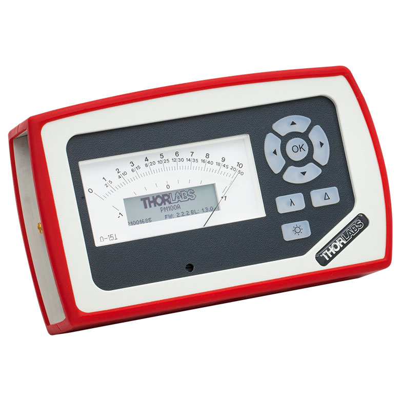 | 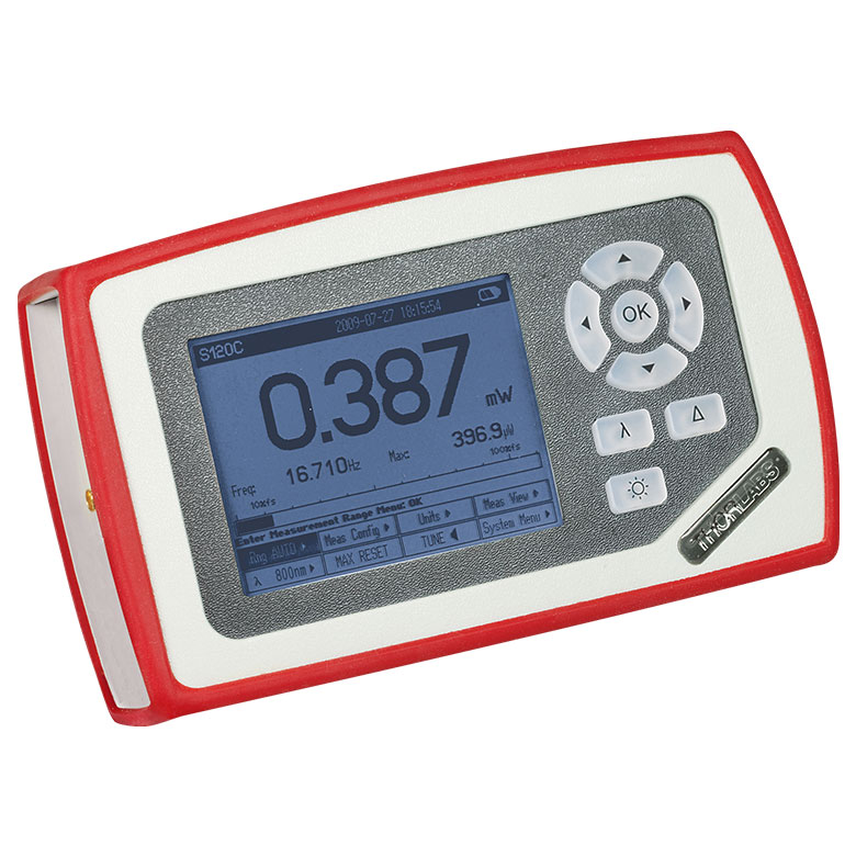 | 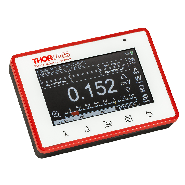 | 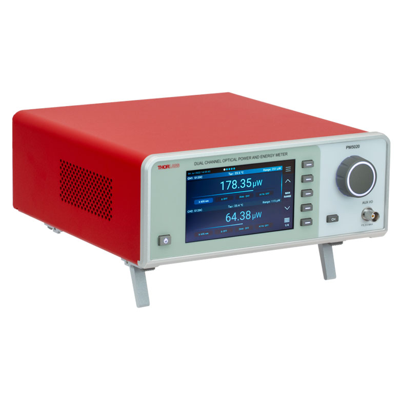 |
| Key Features | Analog Power Measurements | Digital Power and Energy Measurements | Digital Power and Energy Measurements, Touchscreen Control | Dual Channel |
| Compatible Sensors | Photodiode and Thermal Power | Photodiode Power, Thermal Power, and Pyroelectric Energya | Photodiode Power, Thermal Power, Thermal Power and Position, and Pyroelectric Energya | Photodiode Power, Thermal Power, Thermal Power and Position, and Pyroelectric Energy |
| Housing Dimensions (H x W x D) | 7.24" x 4.29" x 1.61" (184 mm x 109 mm x 41 mm) | 7.09" x 4.13" x 1.50" (180 mm x 105 mm x 38 mm) | 5.35" x 3.78" x 1.16" (136.0 mm x 96.0 mm x 29.5 mm) | 9.97" x 4.35" x 11.56" (253.2 mm x 110.6 mm x 293.6 mm) |
| Channels | 1 | 2 | ||
| External Temperature Sensor Input (Sensor not Included) | - | - | Readout and Record Temperature Over Time | Readout and Record Temperature Over Time |
| External Humidity Sensor Input (Sensor not Included) | - | - | Readout and Record Humidity Over Time | Readout and Record Humidity Over Time |
| Input/Output Ports | - | 4 GPIO, Programmable | 4 Configurable Digital I/O Channels | |
| Shutter Control | - | - | - | Support for SH05R(/M) or SH1(/M) Optical Shutter with Interlock Input |
| Fan Control | - | - | - | |
| Source Spectral Correction | - | - | ||
| Attenuation Correction | - | - | ||
| External Trigger Input | - | - | - | |
| Display | ||||
| Type | Mechanical Needle and LCD Display with Digital Readout | 320 x 240 Pixel Backlit Graphical LCD Display | Protected Capacitive Touchscreen with Color Display | |
| Dimensions | Digital: 1.9" x 0.5" (48.2 mm x 13.2 mm) Analog: 3.54" x 1.65" (90.0 mm x 42.0 mm) | 3.17" x 2.36" (81.4 mm x 61.0 mm) | 3.7" x 2.1" (95 mm x 54 mm) | 4.32" x 2.43" (109.7 mm x 61.6 mm) |
| Refresh Rate | 20 Hz | 10 Hz (Numerical) 25 Hz (Analog Simulation) | 25 Hz | |
| Measurement Viewsb | ||||
| Numerical | ||||
| Mechanical Analog Needle | - | - | - | |
| Simulated Analog Needle | - | |||
| Bar Graph | - | |||
| Trend Graph | - | |||
| Histogram | - | - | - | |
| Statistics | ||||
| Memory | ||||
| Type | - | SD Card | NAND Flash | SD Card |
| Size | - | 2 GB | 4 GB | 8 GB |
| Power | ||||
| Battery | LiPo 3.7 V 1300 mAh | LiPo 3.7 V 2600 mAh | - | |
| External | 5 VDC via USB or Included AC Adapter | 5 VDC via USB | Line Voltage: 100 - 240 V | |

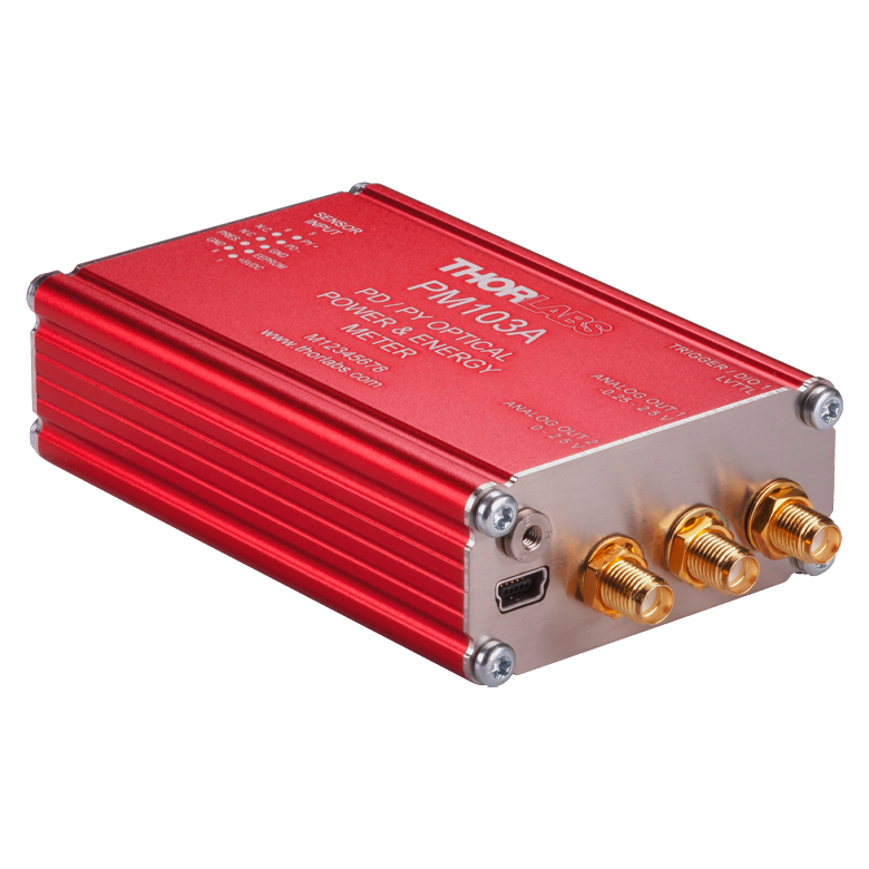
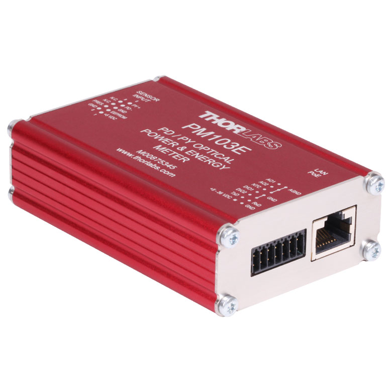
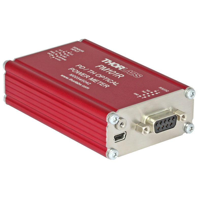
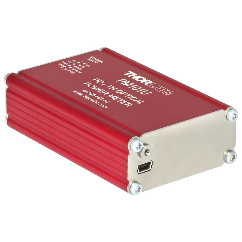


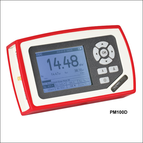 ズーム
ズーム- コンパクトサイズでハンドヘルド型のパワー&エネルギーメーターコンソール
- 大型4インチの液晶画面
- 長寿命のリチウムポリマ電池内蔵
- データ保存用の8 GB SDメモリーカード(取り付け済み)
- Certificate of Calibration(校正証明書)付き
このパワーメータPM100Dにはセンサは含まれておりません。この製品と併用可能な当社のセンサの詳細については下記をご参照ください。なお、このパワーメータPM100Dを当社のセンサと組み合わせたパワーメーターキットもいくつかご用意しております。詳細は製品ページをご覧ください。
PM100Dの再校正サービスも承っております。また、再校正を必要とする対応センサをお持ちの場合、追加の費用無しでセンサの再校正にPM100Dの再校正を含めることが可能です。詳細は当社までお問い合わせください。
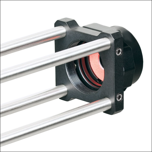
Click to Enlarge
S120Cと簡単脱着式マウントCP44F
- 一般的な光パワー測定用
- センサのアライメントを容易にするビュワーターゲット付き
- センサ開口部:Ø9.5 mm
- センサ、保護キャップ、赤外域用ターゲットが付属
- ファイバーアダプタも別売りでご用意(下記参照)
- 詳細は、こちらをご参照ください。
この標準型フォトダイオードパワーセンサは、UVから近赤外までの低いパワーのコヒーレント光/インコヒーレント光の測定にご使用いただけます。NISTトレーサブル、校正済みで、アライメントが容易になるビュワーターゲットを搭載しており、電磁波干渉に対する遮蔽機能が強化され、過熱警報機能、Ø9.5 mmの大きな開口が特長です。30 mmケージシステム、Ø12 mm~Ø12.7 mm(Ø1/2インチ)ポスト、SM1レンズチューブに取付け可能で、自由空間やファイバ出力光源の測定にも適しています。
当社ではこれらのセンサに対して再校正サービスをご提供しております。再校正サービスの詳細は当社までお問い合わせください。
| Item #a | S120VC | S120C | S121C | S122C |
|---|---|---|---|---|
| Sensor Image (Click the Image to Enlarge) |
|
|
|
|
| Aperture Size | Ø9.5 mm | |||
| Wavelength Range | 200 - 1100 nm | 400 - 1100 nm | 400 - 1100 nm | 700 - 1800 nm |
| Power Range | 50 nW - 50 mW | 500 nW - 500 mW | 50 nW - 40 mW | |
| Detector Type | Si Photodiode (UV Extended) | Si Photodiode | Ge Photodiode | |
| Linearity | ±0.5% | |||
| Resolutionb | 1 nW | 10 nW | 2 nW | |
| Measurement Uncertaintyc | ±3% (440 - 980 nm) ±5% (280 - 439 nm) ±7% (200 - 279 nm, 981 - 1100 nm) | ±3% (440 - 980 nm) ±5% (400 - 439 nm) ±7% (981 - 1100 nm) | ±5% | |
| Responsivityd (Click for Plot) |  Raw Data |  Raw Data |  Raw Data |  Raw Data |
| Coating/Diffuser | Reflective ND (OD1.5)e | Reflective ND (OD1)f | Reflective ND (OD2)g | Absorptive ND (Schott NG9) |
| Head Temperature Measurement | NTC Thermistor 4.7 kΩ | |||
| Housing Dimensions | Ø30.5 mm x 12.7 mm | |||
| Cable Length | 1.5 m | |||
| Post Mountinge,f,g | Universal 8-32 / M4 Tap, Post Not Included | |||
| Aperture Thread | External SM1 (1.035"-40) | |||
| Compatible Fiber Adapters | S120-FC2, S120-FC, S120-APC2, S120-APC, S120-SMA, S120-ST, S120-LC, and S120-SC (Not Included) | |||
| Compatible Consoles | PM400, PM100D, PM100A, and PM5020 | |||
| Compatible Interfaces | PM101, PM101A, PM101R, PM101U, PM103, PM103A, PM103E, PM103U, and PM100USB | |||
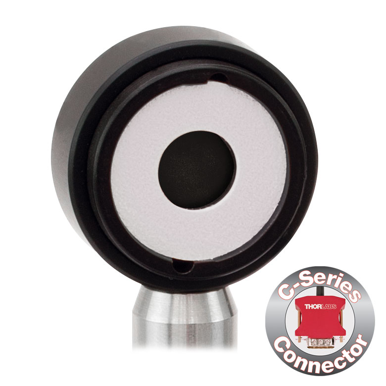

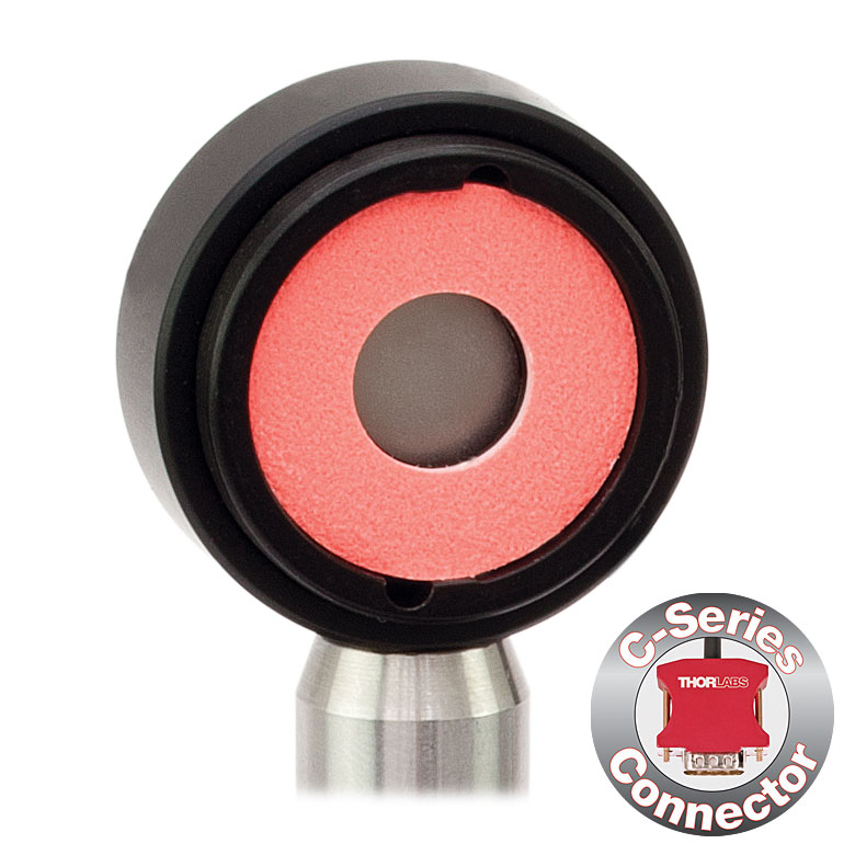
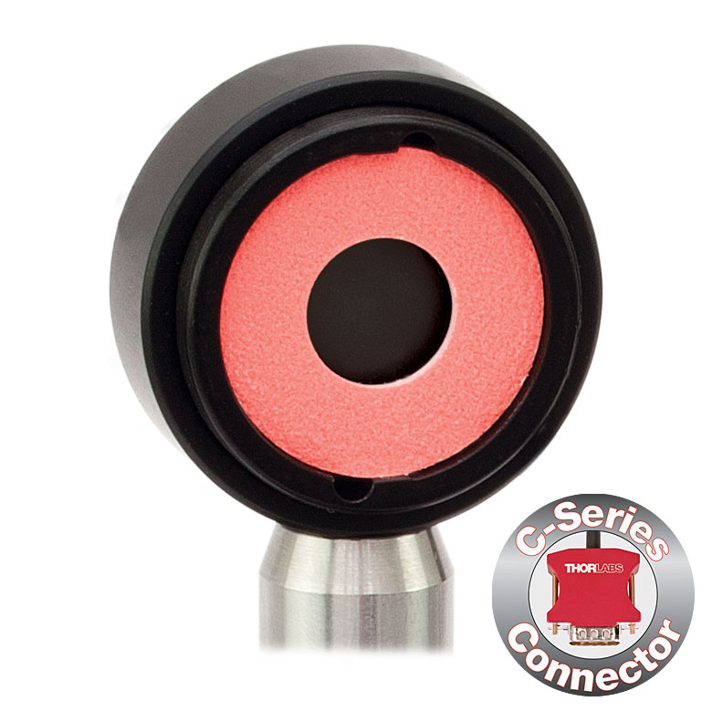
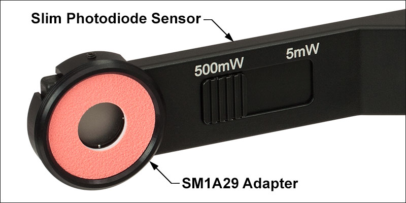
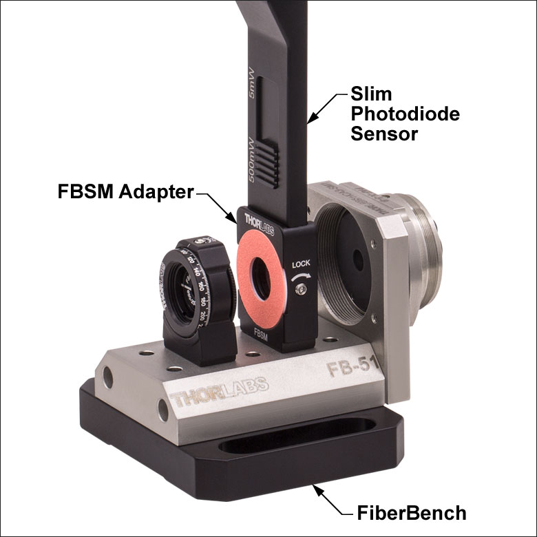
- 限られたスペースでの光パワー測定に
- 薄型設計:センサの厚さ5 mm
- センサ開口部:Ø9.5 mm
- スライド式のNDフィルタがセンサのパワーレンジを自動調整
- VIS/IRターゲットとSM1外ネジ付きアダプタSM1A29を別途ご用意(詳細はこちら)
- FiberBenchシステム用VIS/IRターゲット付きマウントFBSMも別途ご用意(詳細はこちら)
- 詳細はこちらをご参照ください。
こちらの薄型フォトダイオードパワーセンサは、限られたスペースにおいて光パワーが測定できるように設計されています。センサの厚さが僅か5 mmなので、近接配置した光学素子の間やケージシステムの中など、標準のパワーメータを設置することのできない場所でもご使用になれます。NISTトレーサブル、校正済みで、Ø9.5 mmの大きな開口も特長です。また、スライド式のNDフィルタが付いているため、コンパクトなデバイス1つで2つのパワー範囲を測定可能です。
S130シリーズのパワーセンサに、別売りのアダプタSM1A29を2つの止めネジ(セットスクリュ)で取り付けることにより、ファイバーアダプタ、遮光体、フィルタなど、SM1ネジ付き部品を取り付けることができます。マウントFBSMによりS130シリーズのパワーセンサがFiberBenchシステムに垂直方向に取り付けられるため、安定かつ最小の設置面積の取り付けとなります。
当社ではこれらのセンサに対して再校正サービスをご提供しております。詳細については当社までお問い合わせください
| Item #a | S130VC | S130C | S132C | |
|---|---|---|---|---|
| Sensor Image (Click the Image to Enlarge) |
|
|
| |
| Aperture Size | Ø9.5 mm | |||
| Wavelength Range | 200 - 1100 nm | 400 - 1100 nm | 700 - 1800 nmb | |
| Power Range (with Filter) | 500 pW - 0.5 mWc (Up to 50 mW)c | 500 pW - 5 mW (Up to 500 mW) | 5 nW - 5 mW (Up to 500 mW) | |
| Detector Type | Si Photodiode (UV Extended) | Si Photodiode | Ge Photodiode | |
| Linearity | ±0.5% | |||
| Resolution | 100 pWd | 1 nWe | ||
| Measurement Uncertaintyf | ±3% (440 - 980 nm) ±5% (280 - 439 nm) ±7% (200 - 279 nm, 981 - 1100 nm) | ±3% (440 - 980 nm) ±5% (400 - 439 nm) ±7% (981 - 1100 nm) | ±5% | |
| Responsivityg (Click for Plot) | Raw Data | Raw Data | Raw Data | |
| Coating/Diffuser | Reflective ND (OD1.5)c | Reflective ND (OD2)h | Absorptive ND (Schott NG9/KG3)b | |
| Housing Dimensions | 150 mm x 19 mm x 10 mm; 5 mm Thickness on Sensor Side | |||
| Cable Length | 1.5 m | |||
| Post Mounting | 8-32 and M4 Taps | |||
| Adapters (Not Included) | SM1A29: Add SM1 Thread and Viewing Target to Aperture Fiber Adapters Compatible with SM1A29 Adapter: S120-FC2, S120-FC, S120-APC2, S120-APC, S120-SMA, S120-ST, S120-SC, and S120-LC FBSM: Integrate Sensor into FiberBench Setups | |||
| Compatible Consoles | PM400, PM100D, PM100USB, PM100A, and PM5020 | |||
| Compatible Interfaces | PM101, PM101A, PM101R, PM101U, PM103, PM103A, PM103E, PM103U, and PM100USB | |||
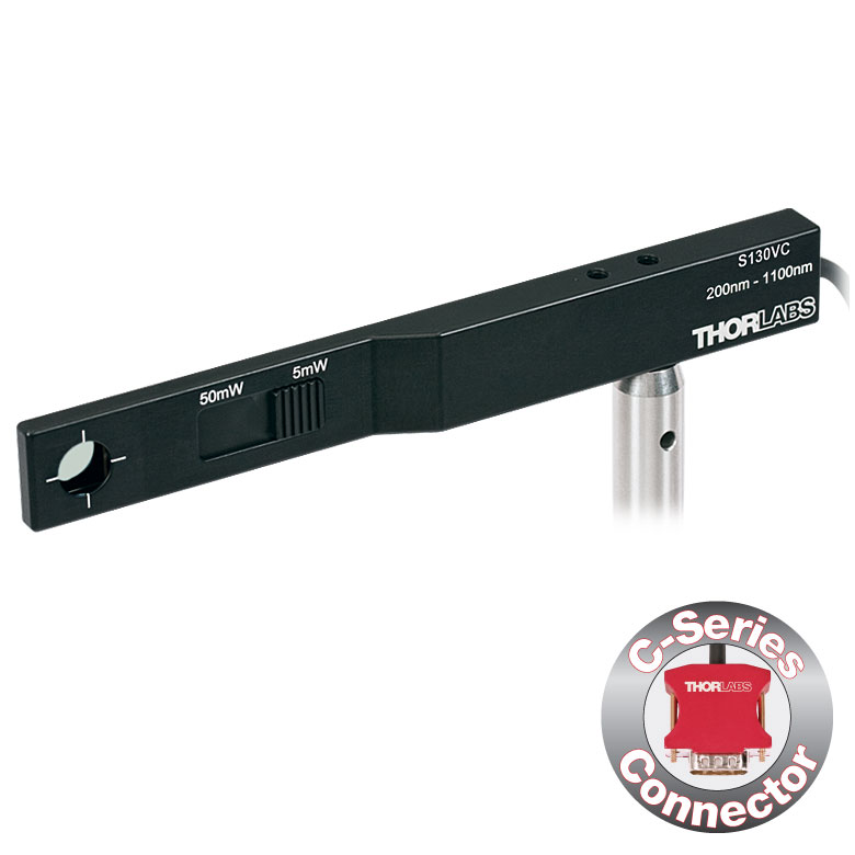
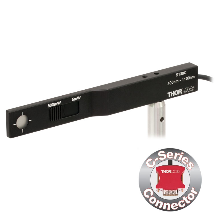
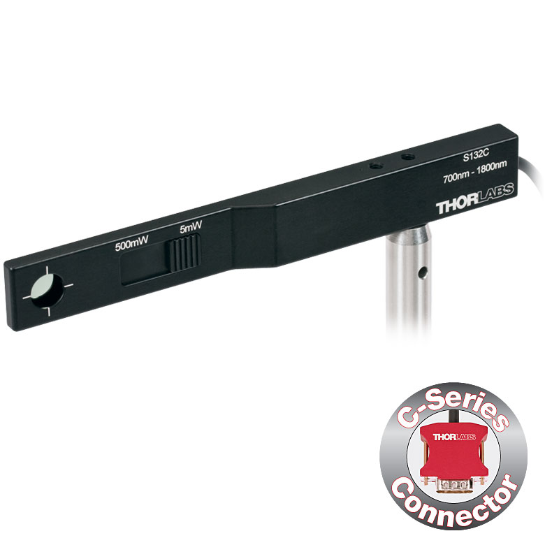
| Item #a | S116C | |
|---|---|---|
| Sensor Image (Click the Image to Enlarge) |
| |
| Aperture Size | Ø6 mm | |
| Wavelength Range | 400 - 1100 nm | |
| Power Range | 20 nW - 50 mW | |
| Detector Type | Si Photodiode | |
| Linearity | ±0.5% | |
| Resolution | 1 nWb | |
| Measurement Uncertaintyc | ±3% (451 - 1000 nm) ±5% (400 - 450 nm, 1001 - 1100 nm) | |
| Responsivityd (Click for Plot) | Raw Data | |
| Coating/Diffuser | Absorptive ND (NG9) | |
| Housing Dimensions (L x W x T) | 70.0 mm x 11.0 mm x 8.9 mm; 10.0 mm Width and 4.5 mm Thickness on Sensor Side | |
| Active Detector Area | 7 mm x 7 mm | |
| Cable Length | 1.5 m | |
| Mounting Threads | 2 Universal 8-32 / M4 Taps (One on the Back, One on the Bottom), Posts Not Included | |
| Adapters (Not Included) | SM05A29: Add SM05 Thread to Aperture Fiber Adapters Compatible with SM05A29 Adapter: PM20-FC2, PM20-FC, PM20-APC2, PM20-APC, PM20-SMA, PM20-ST, PM20-SC, and PM20-LC | |
| Compatible Consoles | PM400, PM100D, PM100A, and PM5020 | |
| Compatible Interfaces | PM101, PM101A, PM101R, PM101U, PM103, PM103A, PM103E, PM103U, and PM100USB | |
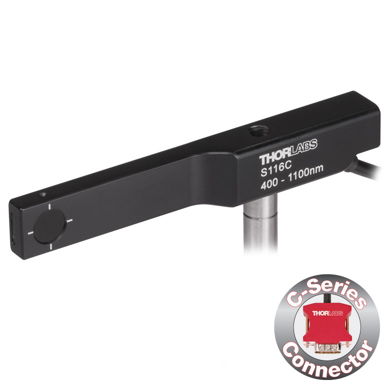
- 16 mmケージシステムなどの狭いスペースでの光パワー測定用
- 波長範囲:400~1100 nm
- 超薄型設計:センサ部の幅10.0 mm、厚さ4.5 mm
- シリコン(Si)フォトダイオード、センサ開口Ø6 mm
- 低パワーレーザ光のパワー測定用
- ポスト取付け用のM4タップ穴
- SM05外ネジ付きアダプタSM05A29は別売りでご用意(詳細はこちら)
- 詳細についてはこちらの製品紹介ページをご覧ください。
コンパクト薄型フォトダイオードパワーセンサS116Cは、スペースやアクセス性が制限された場面でも光パワーが測定できるように設計されています。厚さ4.5 mmのフォトダイオードセンサは、16 mmケージシステムのケージロッドの間(下の写真参照)や、スロット付きØ12 mm~Ø12.7 mm(Ø1/2インチ)レンズチューブ(型番SM05L20CおよびSM05L30C)の側面の穴から挿入することができます。このセンサの開口径はØ6 mmです。
パワーセンサS116Cに、別売りのアダプタSM1A29を2本の1.3 mm六角止めネジ(セットスクリュ)で取り付けると、ファイバーアダプタ、遮光体、フィルタなどのSM05ネジ付き部品を取り付けることができます。アダプタを取り付けたパワーセンサS116Cの写真が下でご覧いただけます。
各センサはNISTまたはPTBトレーサブル校正データとともに発送いたします。ここに含まれるデータは、校正対象センサのスペクトル範囲に対応する、認定された参照用ダイオードを利用して決定されています。当社では、フォトダイオードパワーセンサの再校正サービスをご提供しています。詳細は当社までお問い合わせください。
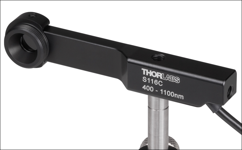
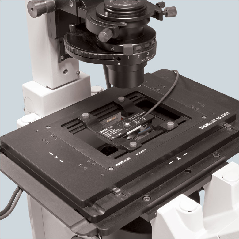
Click for Details
センサ筐体の背面に刻印されたアライメント用ターゲットを利用してステージの位置を決めれば、センサを反転させたときにビームをセンサの中心に入射させることができます。写真のセンサはS170Cです。
- 顕微鏡の試料面での光パワー測定用に設計
- 大きな受光面18 mm x 18 mmのシリコンフォトダイオード
- センサ筐体の寸法:76.0 mm x 25.2 mm x 5.0 mm
- 高NAの対物レンズに適した光学設計
- コネクタに以下の情報を保存
- センサーデータ
- NISTまたはPTBにトレーサブルな校正データ
- M4タップ穴を用いてポストに取り付け可能
このシリコンフォトダイオードが取付けられた顕微鏡用スライド型パワーセンサーヘッドは、顕微鏡システム内の試料面における光パワーを測定するように設計されています。S170Cは波長範囲350 nm~1100 nmに感度があり、10 nW~150 mWの光パワーを測定できます。S171Cは波長範囲400 nm~1100 nmに感度があり、1 nW~15 mWの光パワーを測定できます。センサNS170Cは、中心波長780 nm~1300 nm、平均パワー0.5 mW~350 mWのフェムト秒レーザの相対ピークパワー測定用に設計されています。センサーヘッドの外形寸法76.0 mm x 25.2 mmは標準の顕微鏡用スライドと同じで、標準的な正立および倒立顕微鏡の多くにお使いいただけます。
センサS170CとS171Cに使用されているフォトダイオードの受光面の大きさは18 mm x 18 mmです。このフォトダイオードは密封された筐体に収納されており、その前面にはNDフィルタが付いています。NDフィルタの表面の周囲には段差があり、それにより20 mm x 20 mm大きさの窪みができています。このくぼみには標準的な顕微鏡用カバースリップを入れることができます。液浸材(水、グリセロール、油)は、NDフィルタの上のこのくぼみ内に直接滴下することができます。あるいは、クリーニングを容易にするために、最初にカバースリップを挿入することもできます。フォトダイオードとNDフィルタの間の隙間には屈折率マッチングジェルが充填されています。これは、高開口数(NA)の対物レンズを油浸または水浸で使用したときに、大きな測定誤差の原因となる内部反射を防止するためです。
センサNS170Cは2光子レーザのピークパワーの相対値を測定するように設計されており、2次の非線形結晶であるβ-BBOを用いて近赤外(NIR)の超短パルス入射光を可視(VIS)の第2高調波に変換して検出します。β-BBO結晶の下にあるショートパスフィルタで残留近赤外光が除去され、可視の第2高調波のみがフィルタを透過して大きな面積のシリコン(Si)フォトダイオードセンサに到達します。センサの光入射面には厚さ170 µmのカバーガラスが付いており、これでセンサ筐体を密閉しています。そのため、このセンサはドライ、水浸および油浸用の各対物レンズと組み合わせてご使用いただくことができます。カバーガラス上部からβ-BBO結晶までの作動距離は0.22 mmです。
センサ筐体の背面には、ビームのアライメントや集光の作業を補助するためにグリッドがレーザ刻印されています。標準的な顕微鏡では、このグリッドを用いてビームをアライメントした後、センサーヘッドを反転させて対物レンズに向ければ光パワーの測定を行うことができます。倒立顕微鏡の場合は、透過照明光をオンにしてディテクタ筐体のグリッドとビームを合わせれば、センサの中心が対物レンズの正面にきます。また、NDフィルタの拡散面を集光面として使用することもできます。
センサを損傷させないために、センサを光路上のビームが集光されない位置に配置することをお勧めします。ビームのスポットサイズにおいて、センサS170CおよびS171Cの場合は平均パワー密度の上限値を、NS170Cの場合はピークパワー密度の上限値を超えないことが重要です(下表参照)。
各センサにはNISTまたはPTBにトレーサブルな校正データが添付されます。それらのデータは、各センサの試験に使用されたフォトダイオードの校正証明書のデータと整合しています。センサ仕様とNISTまたはPTBにトレーサブルな校正データは、センサーコネクタ内の不揮発性メモリに保存されており、当社の最新のパワーメーターコンソールで読み出すことができます。センサNS170CのNISTまたはPTBの校正データは、何れもディテクタに可視光が入射する場合のデータであることにご注意ください。しかし、この可視光の強さは近赤外のフェムト秒パルスの照射条件に固有なものになります。精度と性能を維持するために定期的な再校正をお勧めします。校正頻度は用途にもよりますが、通常1年程度です。再校正についての詳細は当社までお問い合わせください。
当社では、サーマルセンサの付いた顕微鏡用スライド型センサーヘッドもご用意しています。詳細はこちらからご覧いただけます。
| Item #a | S170C | S171C | NS170C |
|---|---|---|---|
| Sensor Image (Click Image to Enlarge) | 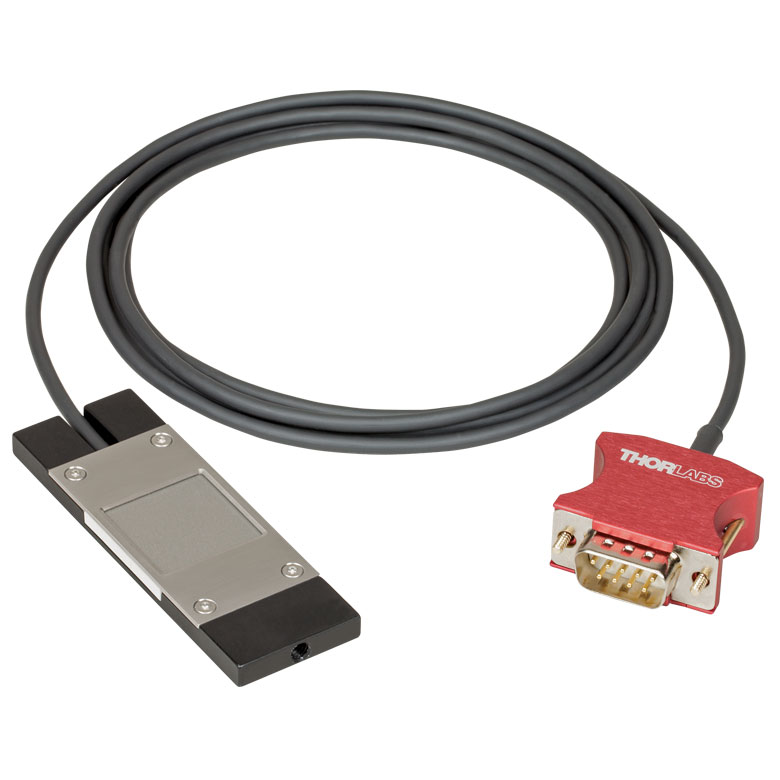 |  | 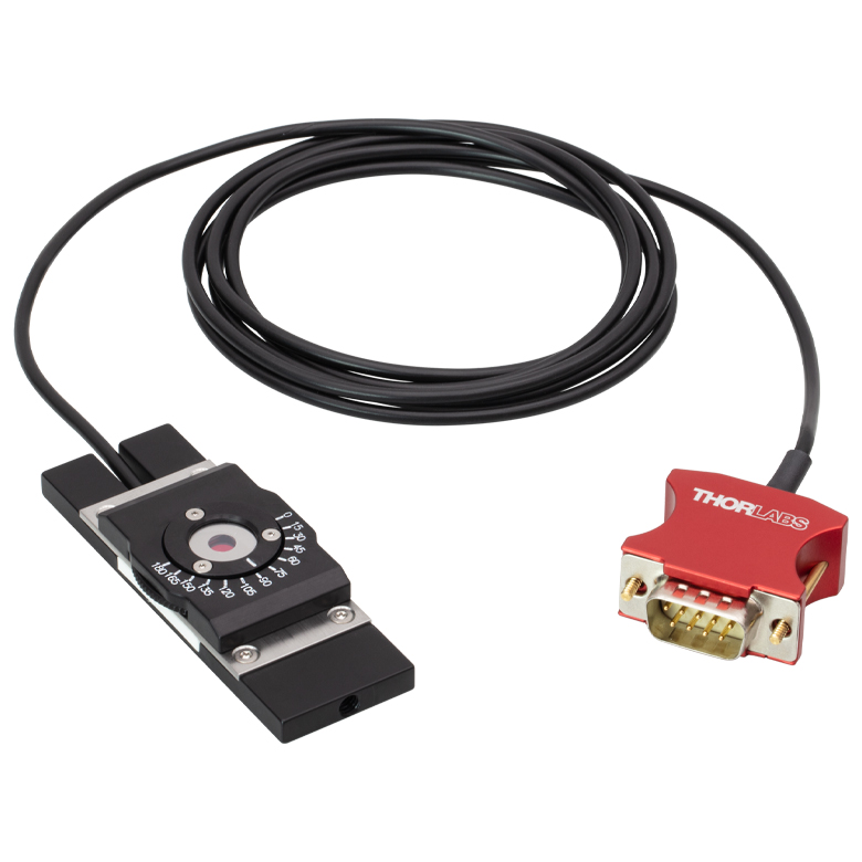 |
| Dimensions | 76.0 mm x 25.2 mm x 5.0 mm (2.99" x 0.99" x 0.20") | Base: 76.0 mm x 25.2 mm x 5.0 mm (2.99" x 0.99" x 0.20") Overall: 76.0 mm x 30.0 mm x 11.0 mm (2.99" x 1.18" x 0.43") | |
| Active Detector Area | 18 mm x 18 mm | ||
| Input Aperture | 20 mm x 20 mm | Ø4.5 mm | |
| Wavelength Range | 350 - 1100 nm | 400 - 1100 nm | Laser: 780 - 1300 nm SHG: 390 - 650 nm |
| Optical Power Working Range | 10 nW - 150 mW | 1 nW - 15 mW | Laser: 0.5 - 350 mWb SHG: 10 nW - 5 mW |
| Max Peak Power Densityc | - | - | 10 TW/cm2 |
| Detector Type | Silicon Photodiode | Second-Order Nonlinear Crystal with Silicon Photodiode | |
| Linearity | ±0.5% | ±0.5%d | |
| Resolution | 1 nWe | 0.5 pWf | 1 nWd,e |
| Measurement Uncertaintyg | ±3% (440 - 980 nm) ±5% (350 - 439 nm) ±7% (981 - 1100 nm) | ±3% (440 - 980 nm)h ±5% (400 - 439 nm)h ±7% (981 - 1100 nm)h | ±3% (440 - 650 nm)d ±5% (390 - 439 nm)d |
| Responsivityi (Click for Plot) |  Raw Data |  Raw Data |  Raw Data |
| Neutral Density Filter | Reflective (OD 1.5) | Absorptive (OD 0.4) | N/A |
| Cable Length | 1.5 m | ||
| Mounting Thread | Universal 8-32 / M4 x 0.7 Tap, Post Not Included | ||
| Compatible Consoles | PM400, PM100D, PM100A, and PM5020 | ||
| Compatible Interfaces | PM101, PM101A, PM101R, PM101U, PM103, PM103A, PM103E, PM103U, and PM100USB | ||
| Item #a | S175C |
|---|---|
| Sensor Image (Click Image to Enlarge) |  |
| Active Detector Area | 18 mm x 18 mm |
| Wavelength Range | 0.3 - 10.6 µm |
| Power Range | 100 µW - 2 W |
| Detector Type | Thermal Surface Absorber (Thermopile) |
| Linearity | ±0.5% |
| Resolutionb | 10 µW |
| Measurement Uncertaintyc | ±3% @ 1064 nm; ±5% @ 300 nm - 10.6 µm |
| Response Time | 3 s (< 2 s from 0 to 90%) |
| Housing Dimensions | 76 mm x 25.2 mm x 4.8 mm (2.99" x 0.99" x 0.19") |
| Cable Length | 1.5 m |
| Housing Features | Integrated Glass Cover Engraved Laser Target on Back |
| Post Mounting | N/A |
| Cage Mounting | N/A |
| Aperture Thread | N/A |
| Compatible Consoles | PM400, PM100D, PM100A, and PM5020 |
| Compatible Interfaces | PM101, PM101A, PM101R, PM101U, PM102, PM102A, PM102U, and PM100USB |
Click to Enlarge
S175C(ガラスおよび吸収体)の典型的な吸収曲線 注: この曲線は典型値であり、実際の吸収スペクトルはユニットごとに異なります。
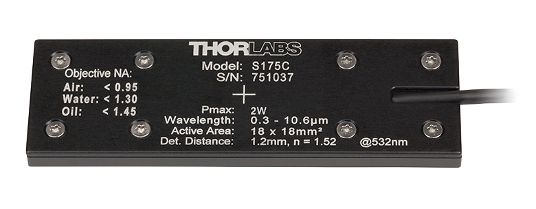
Click to Enlarge
S175Cの筐体の背面には、センサの仕様とビームをセンサの中央に入射させるためのターゲットが刻印されています。
- 波長範囲:300 nm~10.6 μm
- 100 µW~2 Wの光パワーを測定可能
- 顕微鏡の試料面で光パワーを計測できる設計
- 検出部18 mm x 18 mmのサーマルセンサ
- 標準的な顕微鏡スライドと同じ設置面積:76.0 mm x 25.2mm
- コネクタに以下の情報を保存
- センサーデータ
- NISTおよびPTBトレーサブルな校正データ
- 詳細はこちらをご覧ください。
顕微鏡用スライド型サーマルパワーセンサーヘッドS175Cを用いて、顕微鏡システム内の試料面における光パワーを測定できます。こちらのサーマルセンサは、100 µW~2 Wの光パワーで300 nm~10.6 µmの波長を検出できます。76.0 mm x 25.2 mmのセンサーヘッドは、標準の顕微鏡用スライドと同じ設置面積で、多くの標準的な正立および倒立顕微鏡にお使いいただけます。
18 mm x 18 mmの検出部は密封された筐体に収納されており、その上にはガラスカバーが付いています。液浸材(水、グリセロール、油)は、ガラスカバープレートの上につけてください。
右の写真のようにセンサ筐体の背面には、ビームのアライメントと集光を補助するためのターゲットがレーザ刻印されています。標準的な顕微鏡では、このターゲットを用いてビームをアライメントした後、センサーヘッドを反転させて対物レンズに向ければパワーの測定を行うことができます。倒立顕微鏡では、透過照明をオンにしてディテクタ筐体のターゲットとビームを合わせます。これにより、対物レンズの正面中央にセンサがきます。
センサの仕様とNISTおよびPTBトレーサブルな校正データは、センサーコネクタの非揮発性メモリに保存されており、当社の最新世代のパワーメータで読み出すことができます。精度と性能を維持するために年に1度の再校正をお勧めします。当社では、再校正サービスをご提供しております。詳細については当社までお問い合わせください。
仕様の詳細は「仕様」タブをご覧ください。当社では、低パワーで高分解能な測定が可能なフォトダイオードセンサ付き顕微鏡用スライドセンサーヘッドもご用意しております。詳しい製品説明はこちらからご覧いただけます。
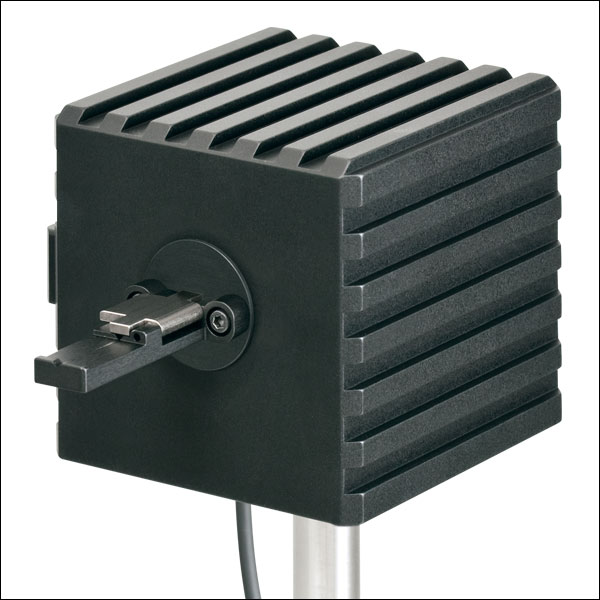
Click to Enlarge
ファイバ素線用アダプタS140-BFA(別売り)を取り付けたS142C
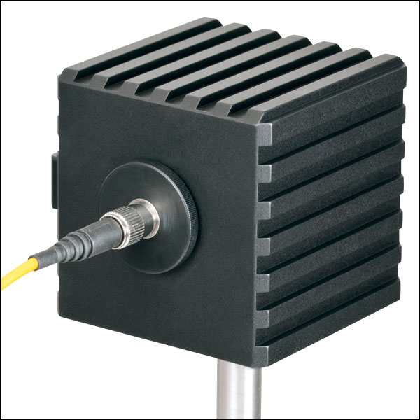
Click to Enlarge
ファイバーアダプタS120-FC(付属)を取り付けたS142C
- ビーム形状や入射角の影響を受けない測定が可能
- 積分球方式により光損失を最小に抑えた拡散板として機能
- センサの入射開口径:Ø5 mm、Ø7 mm、Ø12 mmまたはØ22 mm
- 開口径≤Ø12 mmの積分球には取外し可能なファイバーアダプタS120-FC(FC/PCまたはFC/APCの取付けが可能)が付属
- 開口径≤Ø12 mmの積分球には、終端処理済みファイバ用およびファイバ素線用のアダプタ(下表参照)の取付けが可能
- 詳細はこちらの製品ページをご覧ください。
積分球フォトダイオードパワーセンサは、入射するビームの均一性、広がり角、形状、入射角などに依存せずにパワーを測定するのに適しており、ファイバ光源からの光や光軸から外れた自由空間光などのパワー測定用として優れています。電磁干渉を抑制するためにシールドが強化されており、またセンサの加熱による損傷や測定エラーを防止するために過熱警告センサが付いています。
当社の積分球は、可視~近赤外の波長域用に設計されています。350~2500 nm用のセンサーヘッドには、Zenith® PTFE製のØ25.4 mm(Ø1インチ)またはØ50.8 mm(Ø2インチ)の単一の球が使用されており、入射開口部周辺での反射光を最小限に抑えるために筐体は黒色になっています。波長範囲350~1100 nm用の光検出センサとしてはシリコン(Si)フォトダイオードを、波長範囲800~1700 nm、900~1650 nm、または1200~2500 nm用の光検出センサとしてはInGaAsフォトダイオードを使用しています。
2.9~5.5 µm用の積分球S180Cでは、金メッキされたØ20 mmの球を2つ接続して使用しています。1つめの球に入射ポートが付いており、MCT (HgCdTe)ディテクタ用のポートは2つ目の球に付いています。2つの球を用いる方式では、単一の球を用いる方式と比べると、ディテクタが入射光に直接晒されないように効果的に遮光できるだけでなく、内部の球の表面積を最小限に抑えることもできるため、検出器としての感度が向上します。この方式では、バッフルやその他の遮光機構を使用しなくても、フォトダイオードへの直接入射光を効果的に遮蔽できるため、入射角、広がり角、ビーム形状などによる測定への影響を低減できます。
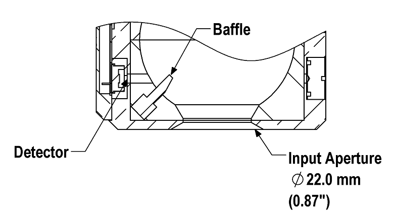
Click to Enlarge
S142CLとS145CLでは、ディテクタに直接光が入射しないようにバッフルを用いて遮光しています。
開口径が Ø5 mm、Ø7 mmまたはØ12 mmの積分球には大きな受光面積の検出器が付いており、また付属のファイバーアダプタS120-FCを取り付けられるSM1外ネジ付きアダプタが付いています。これらのセンサの検出器の受光面積が大きいため、付属のファイバーアダプタS120-FCにはFC/PCまたはFC/APCコネクタ付きファイバを接続することができます。SM1外ネジ付きアダプタはサイズ1のスクリュードライバを使用して取り外せるため、コンポーネントをウィンドウの近くに設置することができます。
積分球S142CLとS145CLの入射開口径はØ22 mmと大きいですが、積分球内のバッフルでフォトダイオードに光が直接入射しないように遮光しています。大きな開口径とバッフルの組み合わせにより、LEDやVCSELのような面積と発散角の大きな光源からの光も測定可能です。ディテクタの入射面には、30 mmケージシステム部品を取り付けるための4つの#4-40ネジが付いています。また、ご要望により、センサーヘッドに第2あるいは第3のポートを付けることも可能です。詳細は当社までお問い合わせください。
各センサにはNISTまたはPTBにトレーサブルな校正データが付いています。それらのデータは、各センサの試験に使用されたフォトダイオードの校正証明書のデータと同じです。NISTまたはPTBにトレーサブルなデータはセンサーコネクタ内に保存されています。当社では、フォトダイオードパワーセンサの再校正サービスをご提供しています。詳細は当社までお問い合わせください。
| Item #a | S140C | S142C | S142CL | S144C | S145C | S145CL | S146C | S148C | S180C | |
|---|---|---|---|---|---|---|---|---|---|---|
| Sensor Image (Click the Image to Enlarge) | 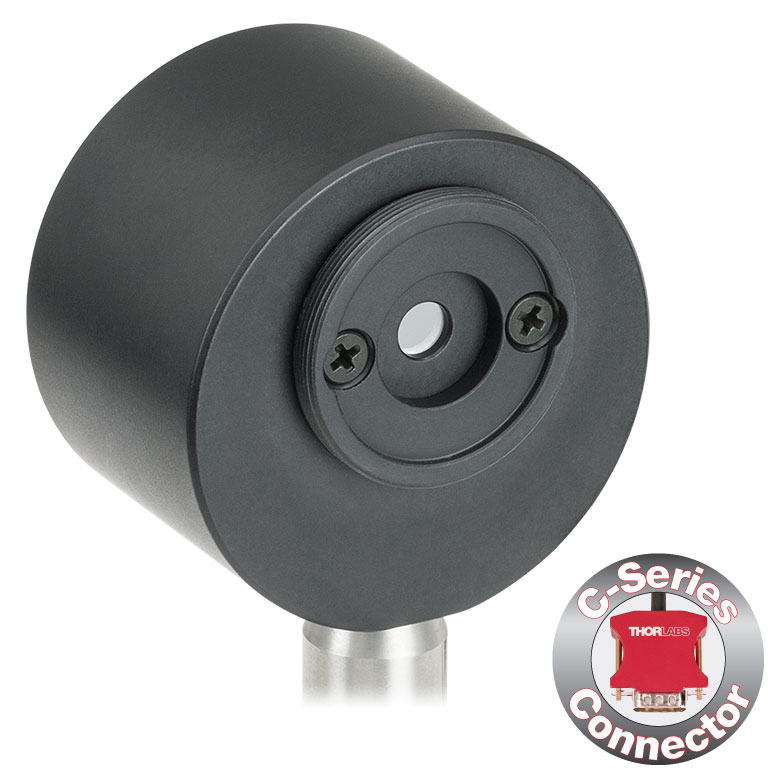 | 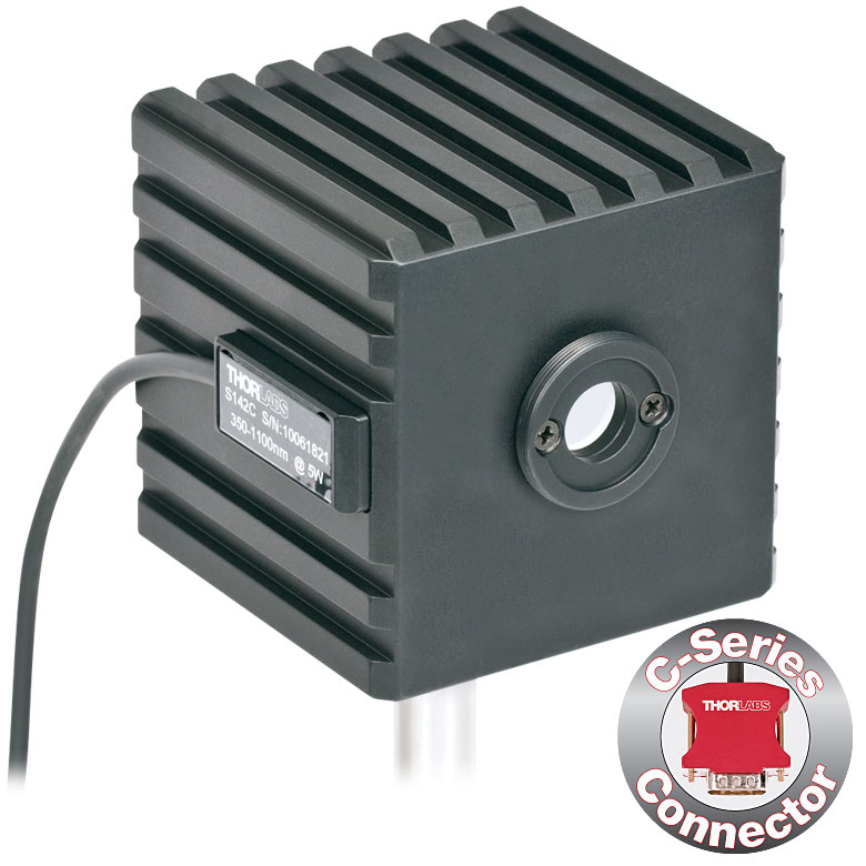 | 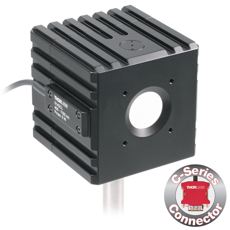 |  | 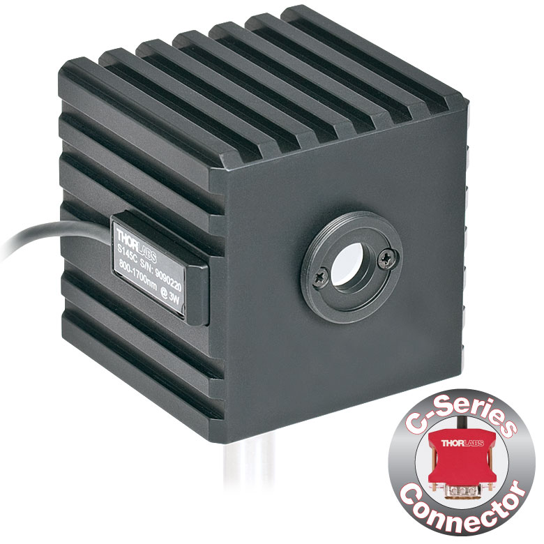 | 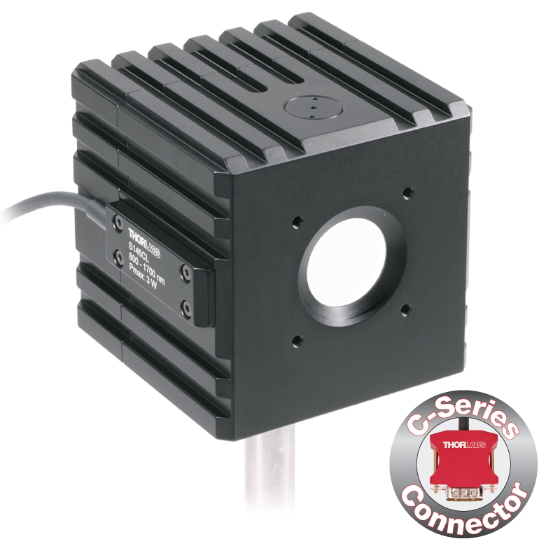 | 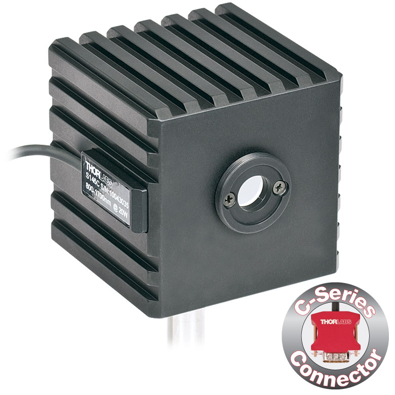 | | 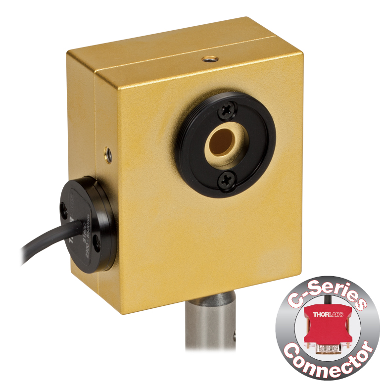 | |
| Aperture Size | Ø5 mm | Ø12 mm | Ø22 mm | Ø5 mm | Ø12 mm | Ø22 mm | Ø12 mm | Ø5 mm | Ø7 mm | |
| Wavelength Range | 350 - 1100 nm | 400 - 1100 nm | 800 - 1700 nm | 900 - 1650 nm | 1200 - 2500 nm | 2.9 µm - 5.5 µm | ||||
| Power Range | 1 µW - 500 mW | 1 µW - 5 W | 10 µW - 5 W | 1 µW - 500 mW | 1 µW - 3 W | 10 µW - 3 W | 10 µW - 20 W | 1 µW - 1 W | 1 µW - 3 W | |
| Detector Type | Si Photodiode | Si Photodiode with Baffle | InGaAs Photodiode | InGaAs Photodiode with Baffle | InGaAs Photodiode | Extended InGaAs Photodiode | MCT (HgCdTe) Photodiode | |||
| Linearity | ±0.5% | |||||||||
| Resolutionb | 1 nW | 10 nW | 1 nW | 10 nW | 1 nW | 10 nW | ||||
| Measurement Uncertaintyc,d | ±3% (440 - 980 nm) ±5% (350 - 439 nm) ±7% (981 - 1100 nm) | ±3% (440 - 980 nm) ±5% (400 - 439 nm) ±7% (981 - 1100 nm) | ±5% | |||||||
| Responsivitye (Click for Plot) |  Raw Data |  Raw Data |  Raw Data |  Raw Data |  Raw Data |  Raw Data |  Raw Data |  Raw Data | Raw Data | |
| Integrating Sphere Material (Size) | Zenith® PTFE (Ø1") | Zenith® PTFE (Ø2") | Zenith® PTFE (Ø1") | Zenith® PTFE (Ø2") | Zenith® PTFE (Ø1") | Gold Plating (Two Ø20 mm Spheres) | ||||
| Head Temperature Measurement | NTC Thermistor 4.7 kΩ | |||||||||
| Housing Dimensions | Ø45 mm x 30.5 mm | 70 mm x 74 mm x 70 mm | Ø45 mm x 30.5 mm | 70 mm x 74 mm x 70 mm | Ø45 mm x 30.5 mm | 59.0 mm x 50.0 mm x 28.5 | ||||
| Active Detector Area | 3.6 mm x 3.6 mm | Ø2 mm | Ø3 mm | Ø1 mm | Ø1 mm | 1 mm x 1 mm | ||||
| Cable Length | 1.5 m | |||||||||
| Mounting Thread | Separate 8-32 and M4 Taps, Posts Not Included | Universal 8-32 / M4 Thread, Post Not Included | Separate 8-32 and M4 Taps, Posts Not Included | Universal 8-32 / M4 Thread, Post Not Included | Separate 8-32 and M4 Taps, Posts Not Included | Universal | ||||
| Aperture Thread | Included Adapter with SM1 (1.035"-40) External Thread | None | Included Adapter with SM1 (1.035"-40) External Thread | None | Included Adapter with SM1 (1.035"-40) External Thread | |||||
| Compatible Fiber Adapters | S120-FC (Included) S120-FC2, S120-APC2, S120-APC, S120-SMA, S120-ST, S120-SC, S120-LC, S120-25, and S140-BFA (Not Included) | None | S120-FC (Included) S120-FC2, S120-APC2, S120-APC, S120-SMA, S120-ST, S120-SC, S120-LC, S120-25, and S140-BFA (Not Included) | None | S120-FC (Included) S120-FC2, S120-APC2, S120-APC, S120-SMA, S120-ST, S120-SC, S120-LC, S120-25, and S140-BFA (Not Included) | |||||
| Compatible Consoles | PM400, PM100D, PM100A, and PM5020 | |||||||||
| Compatible Interfaces | PM101, PM101A, PM101R, PM101U, PM103, PM103A, PM103E, PM103U, and PM100USB | |||||||||

Click to Enlarge
センサS150CとFCケーブルを付けたPM100D
- ファイバ接続による光パワー測定用
- 小型センサがコネクタ内部に収納
- 現場や研究室で使い易い設計
- ファイバーアダプタPM20-FCが付属
- センサS150CおよびS151CにはアダプタPM20-SMAも付属
- 対応するFC/APC、LC/PC、SC/PC、 ST®*ファイバーアダプタもご用意(下表参照)
- 詳細はこちらをご参照ください。
S15xCシリーズのファイバ用小型フォトダイオードパワーセンサは、様々なファイバ出力光源のパワー測定用に設計されています。小型のセンサがパワーメーターコネクタに収納されており、ファイバ入力でNISTトレーサブルなデータ測定を実現します。標準的なFCアダプタ(S150CおよびS151CではSMAアダプタも同様)を、簡単に他の標準的なファイバーアダプタと取り換えることもできます。
当社ではこれらのセンサに対して再校正サービスをご提供しております。詳細については当社までお問い合わせください。
*ST®はLucent Technologies社の登録商標です。
| Item #a | S150C | S151C | S154C | S155C |
|---|---|---|---|---|
| Sensor Image (Click the Image to Enlarge) |
|
|
|
|
| Included Connectors | FCb & SMA | FCb | ||
| Wavelength Range | 350 - 1100 nm | 400 - 1100 nm | 800 - 1700 nm | |
| Power Range | 100 pW to 5 mW (-70 dBm to +7 dBm) | 1 nW to 20 mW (-60 dBm to +13 dBm) | 100 pW to 3 mW (-70 dBm to +5 dBm) | 1 nW to 20 mW (-60 dBm to +13 dBm) |
| Detector Type | Si Photodiode | InGaAs Photodiode | ||
| Linearity | ±0.5% | |||
| Resolutionc | 10 pW (-80 dBm) | 100 pW (-70 dBm) | 10 pW (-80 dBm) | 100 pW (-70 dBm) |
| Measurement Uncertaintyd | ±3% (440 - 980 nm) ±5% (350 - 439 nm) ±7% (981 - 1100 nm) | ±3% (440 - 980 nm) ±5% (400 - 439 nm) ±7% (981 - 1100 nm) | ±5% | |
| Responsivityf (Click for Details) |  Raw Data |  Raw Data |  Raw Data |  Raw Data |
| Coating/Diffuser | N/A | Absorptive ND (Schott NG3) | N/A | |
| Head Temperature Measuremente | NTC Thermistor 3 kΩ | |||
| Aperture Thread | External SM05 (0.535"-40) | |||
| Fiber Adapters | Included: PM20-FC and PM20-SMA Optional: PM20-FC2, PM20-APC2, PM20-APC, PM20-ST, PM20-SC, and PM20-LC | Included: PM20-FC Optional: PM20-FC2, PM20-APC2, PM20-APC, PM20-SMA, PM20-ST, PM20-SC, and PM20-LC | ||
| Compatible Consoles | PM400, PM100D, PM100A, and PM5020 | |||
| Compatible Interfaces | PM101, PM101A, PM101R, PM101U, PM103, PM103A, PM103E, PM103U, and PM100USB | |||

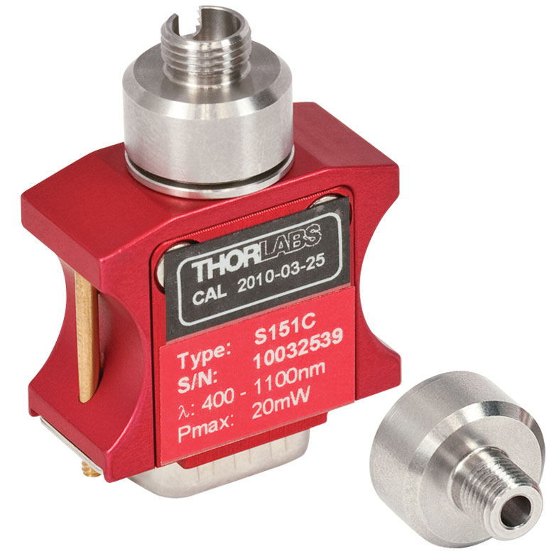
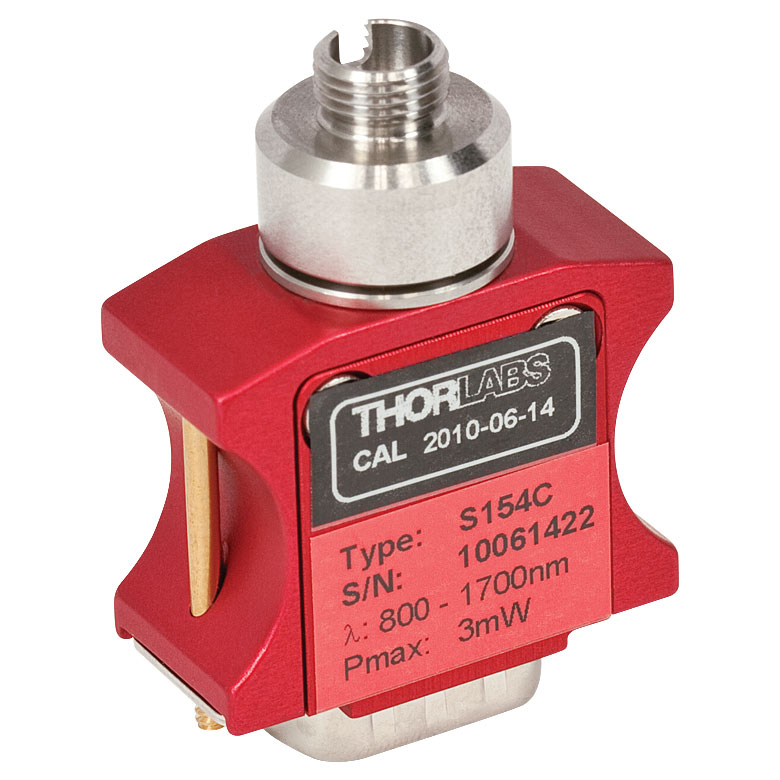

| Item #a | S401C | S405C |
|---|---|---|
| Sensor Image (Click the Image to Enlarge) | 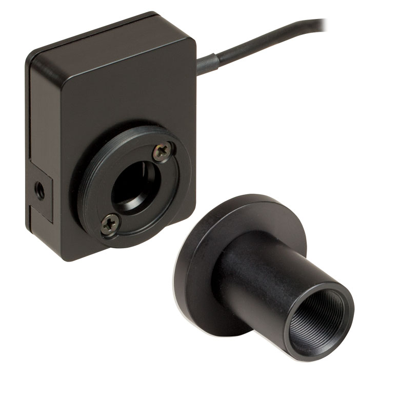 | 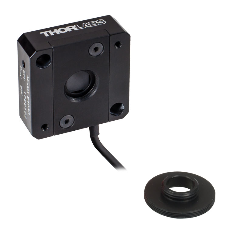 |
| Wavelength Range | 190 nm - 20 µm | 190 nm - 20 µm |
| Optical Power Range | 10 µW - 1 W (3 Wb) | 100 µW - 5 W |
| Input Aperture Size | Ø10 mm | Ø10 mm |
| Active Detector Area | 10 mm x 10 mm | 10 mm x 10 mm |
| Max Optical Power Density | 500 W/cm² (Avg.) | 1.5 kW/cm² (Avg.) |
| Detector Type | Thermal Surface Absorber (Thermopile) with Background Compensation | Thermal Surface Absorber (Thermopile) |
| Linearity | ±0.5% | ±0.5% |
| Resolutionc | 1 µW | 5 µW |
| Measurement Uncertaintyd | ±3% @ 1064 nm ±5% @ 190 nm - 10.6 µm | ±3% @ 1064 nm ±5% @ 250 nm - 17 µm |
| Response Timee | 1.1 s | 1.1 s |
| Cooling | Convection (Passive) | |
| Housing Dimensions (Without Adapter) | (1.30" x 1.69" x 0.59") | 40.6 mm x 40.6 mm x 16.0 mm (1.60" x 1.60" x 0.63") |
| Temperature Sensor (In Sensor Head) | NTC Thermistor | NTC Thermistor |
| Cable Length | 1.5 m | |
| Post Mounting | Universal 8-32 / M4 Taps (Post Not Included) | Universal 8-32 / M4 Taps (Post Not Included) |
| 30 mm Cage Mounting | - | Two 4-40 Tapped Holes & Two Ø6 mm Through Holes |
| Aperture Threads | - | Internal SM05 |
| Accessories | Externally SM1-Threaded Adapter Light Shield with Internal SM05 Threading | Externally SM1-Threaded Adapter |
| Compatible Consoles | PM400, PM100D, PM100A, and PM5020 | |
| Compatible Interfaces | PM101, PM101A, PM101R, PM101U, PM102, PM102A, PM102U, and PM100USB | |
- 1 μWまたは5 μWの高分解能
- S401CとS405Cにはセンサーヘッドの温度をモニタするサーミスタ付き
- S401C: バックグラウンド補正により低ドリフトで測定
- S405C: 最大1.5 kW/cm²の平均パワー密度に対応
- 詳細は、こちらをご覧ください。
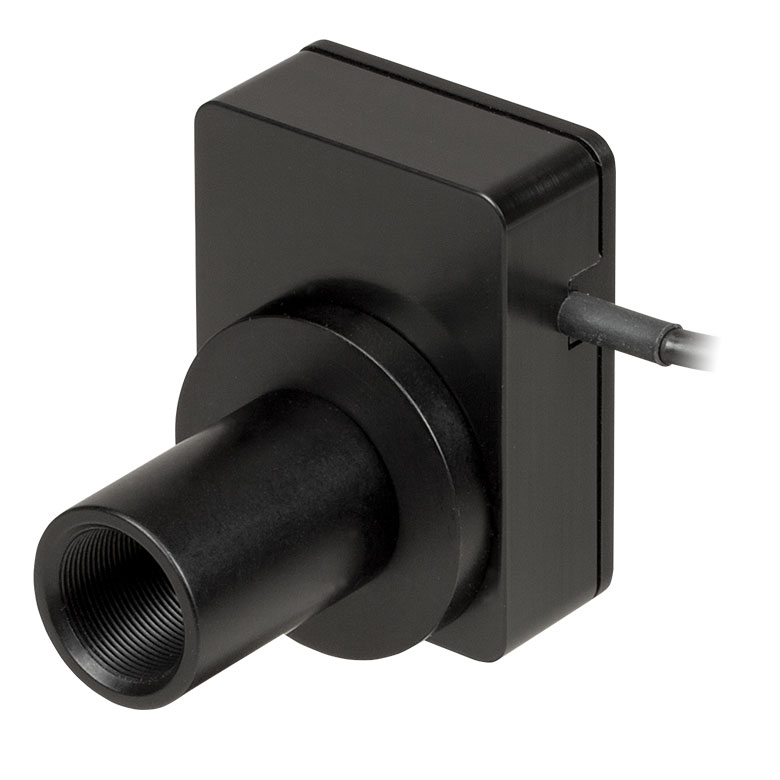
Click to Enlarge
付属の遮光体を取り付けたサーマルセンサS401C
当社では低パワーの光源を高分解能で測定するために設計された広帯域サーマルパワーセンサを3種類ご用意しております。いずれのサーマルセンサの広帯域コーティングも、下のグラフのように広い波長域において平坦なスペクトル応答特性を示します。
Ø10 mmの開口寸法により、スポットサイズの大きいレーザ光源のアライメントや測定が容易です。当社のレンズチューブシステムやSM1ネジ付きファイバーアダプタへの接続用に、各センサにはSM1外ネジが付いているか、あるいはSM1外ネジ付きアダプタが付属しています。
S401Cは、アクティブ型のサーマルバックグラウンド補正により低ドリフトで光パワー測定を行います。これは同様のセンサ回路を2つ使用することで実現しています。1つのセンサ回路はすべてのサーマルパワーセンサが使用するものと同じタイプで、光吸収体からヒートシンクへの熱流量を測定します。もう1つのセンサ回路は周囲温度をモニタします。2つのセンサ回路の測定値が差し引かれるので、レーザーパワー測定におけるサーマルドリフトの影響は最小限に抑えられます (外部からの熱的擾乱がどのようにサーマルパワーセンサの読取値に影響するかについての詳細は、製品ページの「動作」タブをご覧ください)。こちらのサーマルセンサに使用している広帯域コーティングは、0.19~20 µm(グラフ参照)の波長域で高い吸収を示します。そのため、中赤外域(MIR)の量子カスケードレーザ(QCL)のアライメントや測定にお使いいただけます。付属のSM05内ネジ付き遮光体は、上または下の写真でご覧いただけます。
S405CにはSM05内ネジがあり、SM05レンズチューブに直接取り付けられます。また、当社の30 mmケージシステムにも直接取り付けられます。
当社ではこれらのセンサに対して再校正サービスをご提供しております。詳細については当社までお問い合わせください。

Click to Enlarge
S415C、S425C、S245C-Lの吸収曲線はS405と同じです(すべて下記参照)。
| Item #a | S415C | S425C |
|---|---|---|
| Sensor Image (Click Image to Enlarge) | 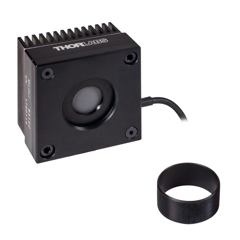 |  |
| Wavelength Range | 190 nm - 20 µm | 190 nm - 20 µm |
| Optical Power Range | 2 mW - 10 W (20 Wb) | 2 mW - 10 W (20 Wb) |
| Input Aperture Size | Ø15 mm | Ø25.4 mm |
| Active Detector Area | Ø15 mm | Ø27 mm |
| Max Optical Power Density | 1.5 kW/cm² (Avg.) | 1.5 kW/cm² (Avg.) |
| Detector Type | Thermal Surface Absorber (Thermopile) | |
| Linearity | ±0.5% | ±0.5% |
| Resolutionc | 100 µW | 100 µW |
| Measurement Uncertaintyd | ±3% @ 1064 nm ±5% @ 250 nm - 17 µm | ±3% @ 1064 nm ±5% @ 250 nm - 17 µm |
| Response Timee | 0.6 s | 0.6 s |
| Cooling | Convection (Passive) | |
| Housing Dimensions (Without Adapter) | (2.00" x 2.00" x 1.38") | (2.00" x 2.00" x 1.38") |
| Temperature Sensor (In Sensor Head) | NTC Thermistor | |
| Cable Length | 1.5 m | |
| Post Mounting | Universal 8-32 / M4 Taps (Post Not Included) | Universal 8-32 / M4 Taps (Post Not Included) |
| 30 mm Cage Mounting | - | - |
| Aperture Threads | Internal SM1 | Internal SM1 |
| Removable Heatsink | Yes | Yes |
| Accessories | Externally SM1-Threaded Adapter | Externally SM1-Threaded Adapter |
| Compatible Consoles | PM400, PM100D, PM100A, and PM5020 | |
| Compatible Interfaces | PM101, PM101A, PM101R, PM101U, PM102, PM102A, PM102U, and PM100USB | |
- 光パワーの分解能は100 µW
- センサーヘッドの温度をモニタするサーミスタ付き
- 取外し可能なヒートシンク
- 詳細はこちらをご覧ください
こちらのサーマルパワーセンサは、低~中程度の広いパワー範囲の測定用に設計されています。全ての製品には入射開口部と同心のSM1外ネジ付きアダプタが付属します。このアダプタはØ25 mm~Ø25.4 mm(Ø1インチ)レンズチューブを取り付ける際に便利です(下記参照)。S415CおよびS425Cの開口にはSM1内ネジが付いています。
このセンサの応答時間は0.6秒以下です。ヒートシンクは取り外しが可能なため、カスタム仕様のセットアップに組み込んだり、ヒートシンクを取り外して水冷式やファン空冷式のものに取り換えるなどのご要望にも対応します。ヒートシンクを交換する場合には、交換後のヒートシンクが用途に適した放熱を行えるようにしてください。
当社ではこれらのセンサに対して再校正サービスをご提供しております。詳細については当社までお問い合わせください。
Click to Enlarge
低~中程度の広いパワー範囲に対応したサーマルパワーセンサの吸収曲線。
Click to Enlarge
低~中程度の広いパワー範囲に対応したサーマルパワーセンサの吸収曲線。
- センサーヘッドの温度をモニタするサーミスタ付き
- S322Cには当社の30 mmケージシステムに対応した#4-40タップ穴付き
- S350Cにはスポットサイズの大きなエキシマレーザなどに適したØ40 mmの開口付き
- S425C-Lには取外し可能なヒートシンク
- S322Cはファン空冷式で光パワーの測定範囲は最大200 W
- 詳細は、こちらをご参照ください。
こちらのサーマルパワーセンサは、低~中程度の広いパワー範囲の測定用に設計されています。 S350Cを除くすべての製品には、入射開口部と同心のSM1外ネジ付きアダプタが付属します。これによって、センサにはファイバーアダプタ(下記参照)が使用可能です。また、既存のØ25 mm~Ø25.4 mm(Ø1インチ)レンズチューブに組み込むこともできます。S425C-Lの開口にはSM1内ネジが付いています。
S425C-Lのセンサの応答時間は0.6秒以下です。ヒートシンクは取り外しが可能なため、カスタム仕様のセットアップに組み込んだり、ヒートシンクを取り外して水冷式やファン空冷式のものに取り換えるなどのご要望にも対応します。ヒートシンクを交換する場合には、交換後のヒートシンクが用途に適した放熱を行えるようにしてください。
当社ではこれらのセンサに対して再校正サービスをご提供しております。詳細については当社までお問い合わせください。
| Item #a | S350C | S425C-L | S322C |
|---|---|---|---|
| Sensor Image (Click Image to Enlarge) | 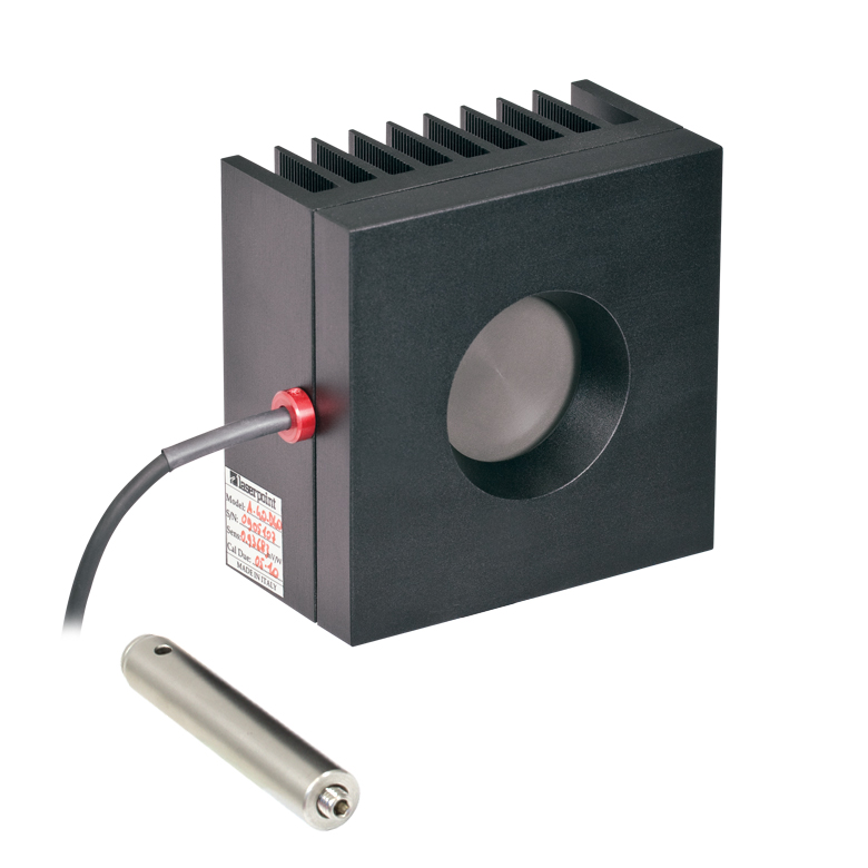 |  |  |
| Wavelength Range | 190 nm- 1.1 µm, 10.6 µm | 190 nm - 20 µm | 250 nm - 11 µm |
| Optical Power Range | 10 mW - 40 W (60 Wb) | 2 mW - 50 W (75 Wb) | 100 mW - 200 W (250 Wb) |
| Input Aperture Size | Ø40 mm | Ø25.4 mm | Ø25 mm |
| Active Detector Area | Ø40 mm | Ø27 mm | Ø25 mm |
| Max Optical Power Density | 2 kW/cm² (Avg.) | 1.5 kW/cm² (Avg.) | 4 kW/cm² (Avg., CO2) |
| Detector Type | Thermal Surface Absorber (Thermopile) | ||
| Linearity | ±1% | ±0.5% | ±1% |
| Resolutionc | 1 mW | 100 µW | 5 mW |
| Measurement Uncertaintyd | ±3% @ 1064 nm ±5% @ 190 nm - 1100 nm, 10.6 µm | ±3% @ 1064 nm ±5% @ 250 nm - 17 µm | ±3% @ 1064 nm ±5% @ 266 nm - 1064 nm |
| Response Timee | 9 s (1 s from 0 to 90%) | 0.6 s | 5 s (1 s from 0 to 90%) |
| Cooling | Convection (Passive) | Forced Air with Fanf | |
| Housing Dimensions (Without Adapter, if Applicable) | 100 mm x 100 mm x 54.2 mm (3.94" x 3.94" x 2.13") | 100.0 mm x 100.0 mm x 58.0 mm (3.94" x 3.94" x 2.28") | 100 mm x 100 mm x 86.7 mm (3.94" x 3.94" x 3.41") |
| Temperature Sensor (In Sensor Head) | NTC Thermistor | ||
| Cable Length | 1.5 m | ||
| Post Mounting | M6 Threaded Taps, Includes Ø1/2" Post, 75 mm Long | Universal 8-32 / M4 Taps (Post Not Included) | M6 Threaded Taps, Includes Ø1/2" Post, 75 mm Long |
| 30 mm Cage Mounting | - | - | Four 4-40 Tapped Holes |
| Aperture Threads | - | Internal SM1 | - |
| Removable Heatsink | - | Yes | - |
| Accessories | - | Externally SM1-Threaded Adapter | Externally SM1-Threaded Adapter |
| Compatible Consoles | PM400, PM100D, PM100A, and PM5020 | ||
| Compatible Interfaces | PM101, PM101A, PM101R, PM101U, PM102, PM102A, PM102U, and PM100USB | ||
| Item #a | S370C | S470C |
|---|---|---|
| Sensor Image (Click the Image to Enlarge) | 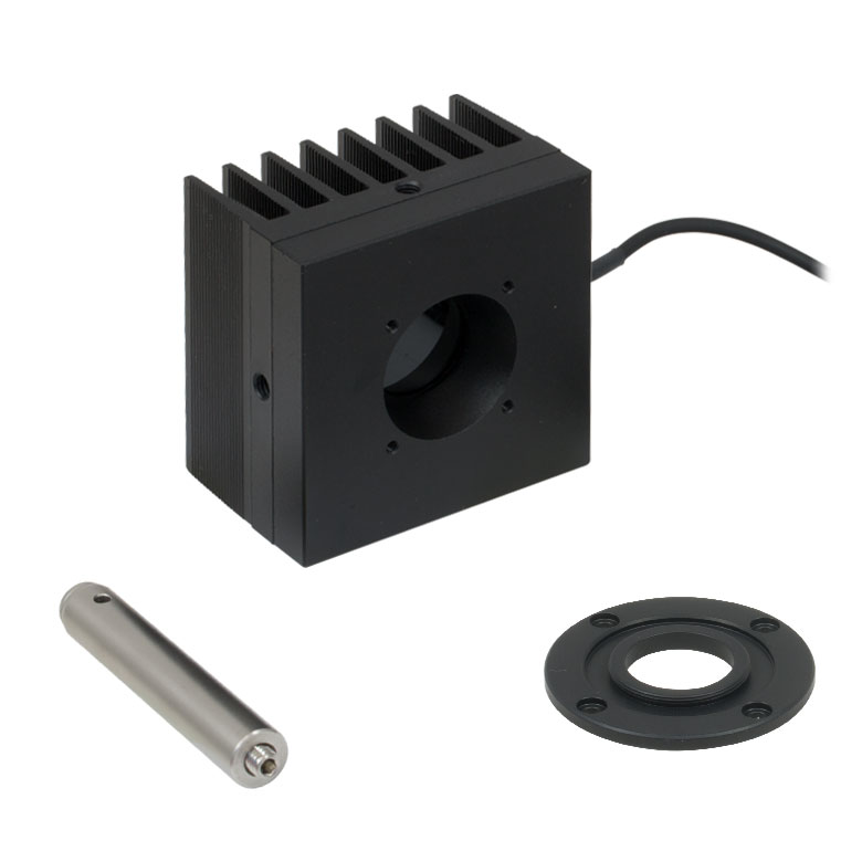 | 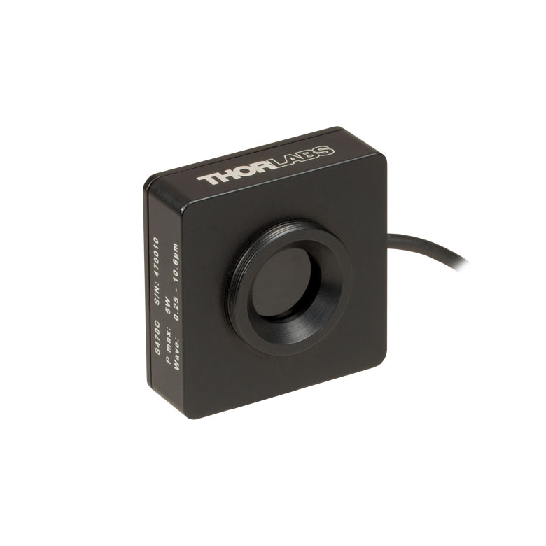 |
| Wavelength Range | 400 nm - 5.2 µm | 250 nm - 10.6 µm |
| Optical Power Range | 10 mW - 10 W (15 Wb) | 100 µW - 5 W (Pulsed and CW) |
| Input Aperture Size | Ø25 mm | Ø15 mm |
| Active Detector Area | Ø25 mm | Ø16 mm |
| Max Optical Power Density | 35 W/cm² (Avg.); 100 GW/cm² (Peak) | |
| Detector Type | Thermal Volume Absorber (Thermopile) | |
| Linearity | ±1% | ±0.5% |
| Resolutionc | 250 µW | 10 µW |
| Measurement Uncertaintyd | ±3% @ 1064 nm ±5% @ 400 nm - 1064 nm | ±3% @ 1064 nm ±5% @ 250 nm - 10.6 µm |
| Response Timee | 45 s (3 s from 0 to 90%) | 6.5 s (<2 s from 0 to 90%) |
| Cooling | Convection (Passive) | |
| Housing Dimensions (Without Adapter, if Applicable) | (2.95" x 2.95" x 2.02") | (1.77" x 1.77" x 0.71") |
| Temperature Sensor (In Sensor Head) | N/A | N/A |
| Cable Length | 1.5 m | |
| Post Mounting | M6 Threaded Taps, Includes Ø1/2" Post, 75 mm Long | Universal 8-32 / M4 Tap (Post Not Included) |
| 30 mm Cage Mounting | Four 4-40 Tapped Holes | - |
| Aperture Threads | - | External SM1 |
| Accessories | - | |
| Compatible Consoles | PM400, PM100D, PM100A, and PM5020 | |
| Compatible Interfaces | PM101, PM101A, PM101R, PM101U, PM102, PM102A, PM102U, and PM100USB | |
- Nd:YAGレーザの光パワー測定用
- ピークパワーの大きなパルスレーザに適した製品
- S370C: スポットサイズの大きなビームに対応したØ25 mmの開口
- S470C: 平均パワーが小さく、ピークパワーが大きなパルスレーザに対して高感度
- 詳細は、こちらをご参照ください。
サーマルセンサS370CならびにS470Cは、高エネルギーの短パルスレーザ用に設計されています。 すべてのユニットは自由空間光を測定するためにポストに取り付けることができ、またセンサのコネクタ部にはNISTトレーサブルなデータが保存されています。
これらのサーマルパワーセンサは体積吸収体を使用している点がユニークな特長です。他のサーマルパワーセンサでは表面吸収体が使用されています。体積吸収体はSchott社製ガラスフィルタでできています。入射パルスは吸収され、熱は体積全体に分散されます。このため、表面吸収体の吸収コーティングを損傷するようなパルスでも、体積吸収体ではより安全に測定することができます。
S370Cの開口部はØ25 mmと大きく、スポットサイズが大きいビームの測定に適しており、平均パワー10 mW~10 W(CW)に対応しています。
S370Cと比較してS470Cは応答が速くなっていますが、これはガラス吸収体の体積が小さく、またその他の設計パラメータも速度を上げるために最適化されているためです。その結果、光パワーの測定範囲も異なり、100 µWの低いパワーまで測定できます。S470Cの開口部はØ15 mmと小さく、また最大平均パワーも5 Wと小さくなっています。分解能は10 µWで、S370Cの250 µWと比較して優れています。
当社ではこれらのセンサに対して再校正サービスをご提供しております。詳細については当社までお問い合わせください。
Click to Enlarge
この吸収曲線はセンサの動作範囲よりも広い波長範囲を表示しています。各センサの動作波長範囲については表をご覧ください。
| Item #a | ES111C | ES120C | ES145C |
|---|---|---|---|
| Sensor Image (Click the Image to Enlarge) | 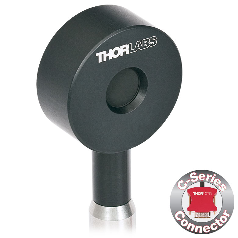 | 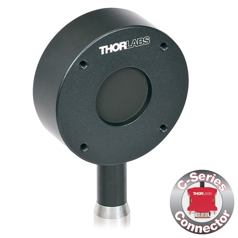 | 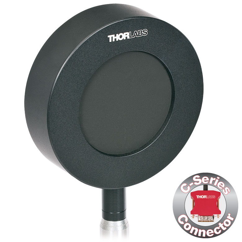 |
| Input Aperture Size | Ø11 mm | Ø20 mm | Ø45 mm |
| Wavelength Range | 0.185 - 25 µm | ||
| Energy Range | 10 µJ - 150 mJ | 100 µJ - 500 mJ | 500 µJ - 2 J |
| Max Repetition Rateb | 40 Hz | 30 Hz | 30 Hz |
| Max Power Density (Pulse Width) | 8 MW/cm2 (10 ns Pulse) | ||
| Max Pulse Energy Density (Pulse Width) | 0.15 J/cm2 (1 µs Pulse) | ||
| Coating (Click for Plot) | Black Broadband | ||
| Resolution | 100 nJ | 1 µJ | 1 µJ |
| Linearity | ±1% | ||
| Measurement Uncertainty | ±5% @ 190 nm - 25 µm | ±5% @ 185 nm - 25 µm | ±5% @ 185 nm - 25 µm |
| Housing Dimensions | Ø36 mm x 16 mm | Ø50 mm x 18 mm | Ø75 mm x 21 mm |
| Active Detector Area | 95.0 mm2 | 314.2 mm2 | 1590.4 mm2 |
| Cable Length | 1.5 m (60") | ||
| Post Mounting | 8-32 Mounting Thread, 8-32 and M4 Insulating Adapters Included | ||
| Cage Mounting | N/A | Four 4-40 Threaded Holes for 30 mm Cage Systems | N/A |
| Compatible Consoles | PM400, PM100D, and PM5020 | ||
| Compatible Interfaces | PM103, PM103A, PM103E, PM103U, and PM100USB | ||
- 一般的な光パルス測定用
- 広い波長範囲で平坦な波長応答性を実現する黒色の広帯域コーテイング
- 検出部:Ø11 mm、Ø20 mm、Ø45 mm
- オシロスコープ用のBNCコネクタ
- 各センサの付属品
- 当社のコンソールと使用可能なCシリーズのコネクターアダプタ(下表または「コンソールセレクション」タブ参照)
- 電気的に絶縁されたポスト用アダプタ(ミリ規格品とインチ規格品それぞれ1つずつ)
- 詳細についてはこちらの製品紹介ページをご覧ください。
標準焦電センサES1xxCは、コヒーレント光源およびインコヒーレント光源からのパルス測定用に設計されています。焦電センサは、光パルスのエネルギを電圧パルスに変換する測定原理であるため、CW光源の測定には適しません。黒色広帯域コーティングの平坦な吸収プロファイルにより(下表参照)、低パワーで波長に無依存なエネルギ測定に適します。検出部がØ11 mm、Ø20 mm、Ø45 mmと大きいため、アライメントが容易です。また、これらのセンサは、BNCコネクタを介して1 MΩ入力抵抗のオシロスコープに直接接続することができます。高い繰返しレートのパルスをオシロスコープで測定する場合、負荷抵抗を下げることで対応が可能です。各エネルギーセンサには、NISTおよびPTBにトレーサブルの校正データが付いたBNC-Cシリーズ変換アダプタも含まれます。
当社では、エネルギーセンサの再校正サービスをご提供しています。詳細については当社までお問い合わせください。
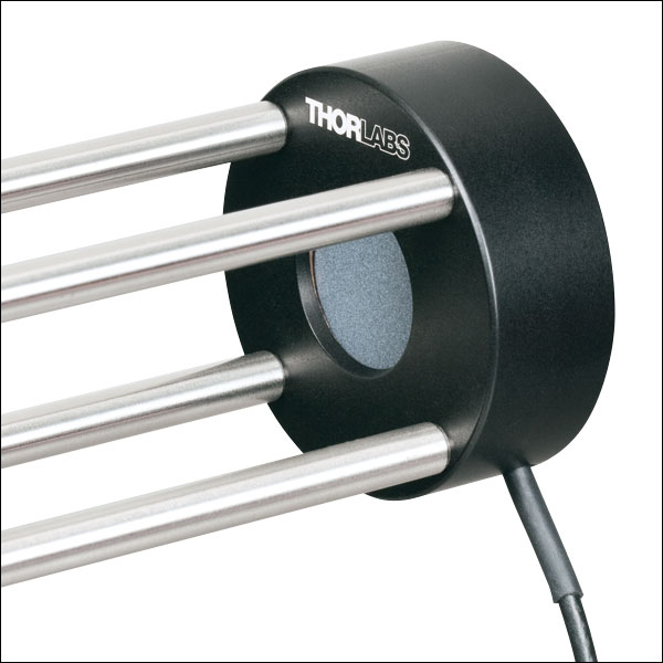
Click to Enlarge
30 mmケージシステムに取り付けたセンサES220C
- 最大15 Jまでの高エネルギ光パルスの測定が可能
- 高エネルギ密度レーザ(最大0.45 J/cm2)用に高い損傷閾値のセラミックコーティング
- 検出部: Ø20 mmまたはØ45 mm
- オシロスコープ用のBNCコネクタ
- 各センサの付属品
- 当社のコンソールと使用可能なCシリーズのコネクターアダプタ(下表または「コンソールセレクション」タブ参照)
- 電気的に絶縁されたポスト用アダプタ(ミリ規格品とインチ規格品それぞれ1つずつ)
- 詳細はこちらの製品紹介ページをご参照ください。
高エネルギ焦電センサES2xxCは、コヒーレント光源およびインコヒーレント光源からのパルス測定用に設計されています。焦電センサは、光パルスのエネルギを電圧パルスに変換する測定原理であるため、CW光源の測定には適しません。セラミックコーティングが使用されているため、センサES220Cでは3 Jまで、ES245Cでは15 Jまでの高エネルギ測定が可能です。検出部がØ20 mmまたはØ45 mmと大きいため、アライメントが容易です。また、これらのセンサは、BNCコネクタを介して1 MΩ入力抵抗のオシロスコープに直接接続することができます。高い繰返しレートのパルスをオシロスコープで測定する場合、負荷抵抗を下げることで対応が可能です。各エネルギーセンサには、NISTおよびPTBにトレーサブルの校正データが付いたBNC-Cシリーズ変換アダプタも含まれます。
当社では、エネルギーセンサの再校正サービスをご提供しています。詳細については当社までお問い合わせください。
| Item #a | ES220C | ES245C |
|---|---|---|
| Sensor Image (Click the Image to Enlarge) | 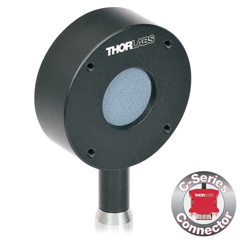 | 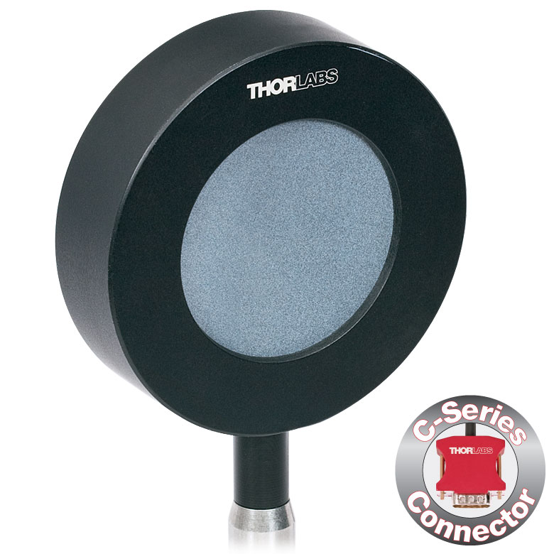 |
| Input Aperture Size | Ø20 mm | Ø45 mm |
| Wavelength Range | 0.185 - 25 µm | |
| Energy Range | 500 µJ - 3 J | 1 mJ - 15 J |
| Max Repetition Rateb | 30 Hz | 30 Hz |
| Max Power Density (Pulse Width) | 65 MW/cm2 (7 ns Pulse @ 355 nm) | |
| Max Pulse Energy Density (Pulse Width) | 0.45 J/cm2 (7 ns Pulse @ 355 nm) | |
| Coating (Click for Plot) | Ceramic | |
| Resolution | 25 µJ | 50 µJ |
| Linearity | ±1% | |
| Measurement Uncertainty | ±5% @ 0.185 - 25 µm | |
| Housing Dimensions | Ø50 mm x 18 mm | Ø75 mm x 21 mm |
| Active Detector Area | 314.2 mm2 | 1590.4 mm2 |
| Cable Length | 1.5 m (60") | |
| Post Mounting | 8-32 Mounting Thread, 8-32 and M4 Insulating Adapters Included | |
| Cage Mounting | Four 4-40 Threaded Holes for 30 mm Cage Systems | N/A |
| Compatible Consoles | PM400, PM100D, and PM5020 | |
| Compatible Interfaces | PM103, PM103A, PM103E, PM103U, and PM100USB | |
| Item #a | ES308C | ES312C | ES412C |
|---|---|---|---|
| Sensor Image (Click the Image to Enlarge) | 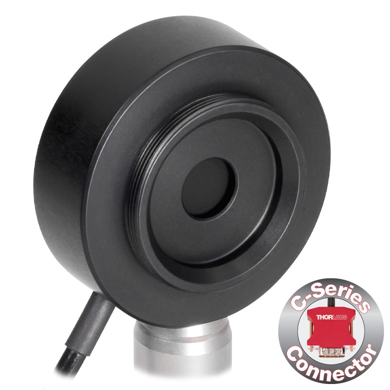 | 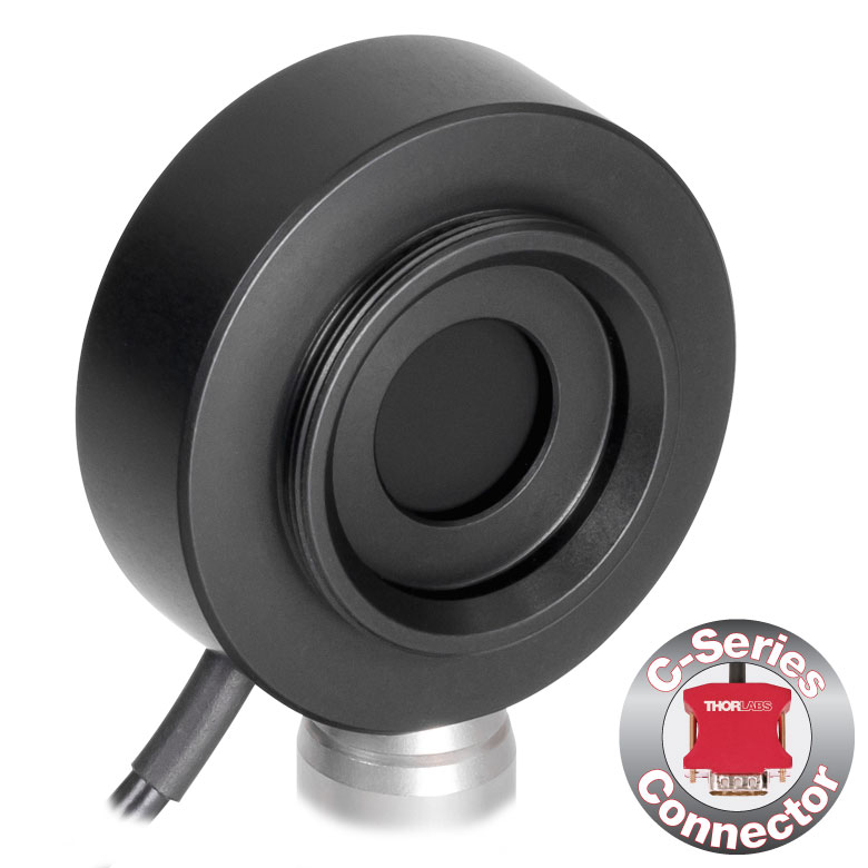 | 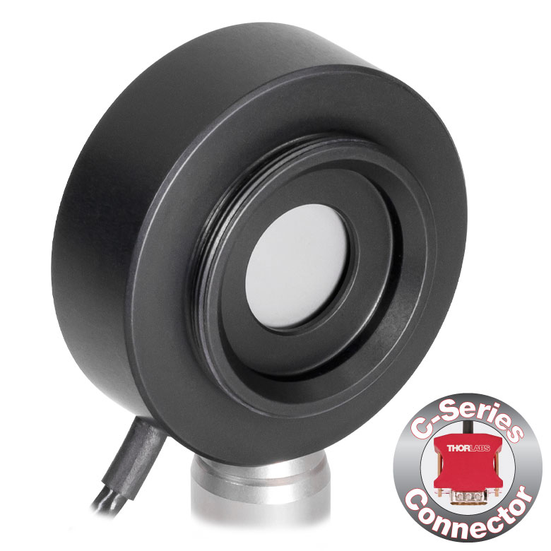 |
| Input Aperture Size | Ø8 mm | Ø12 mm | Ø12 mm |
| Wavelength Range | 0.185 - 25 µm | 0.185 - 25 µm | 0.185 - 2.5 µm |
| Energy Range | 500 µJ - 1 J | 100 µJ - 1 J | 50 µJ - 500 mJ |
| Max. Repetition Rateb | 1 kHz | 250 Hz | 2 kHz |
| Max Power Density (Pulse Width) | 8 MW/cm2 (10 ns Pulse) | 5 MW/cm2 (10 ns Pulse) | |
| Max Pulse Energy Density (Pulse Width) | 80 mJ/cm2 (10 ns Pulse) | 50 mJ/cm2 (10 ns Pulse) | |
| Coating (Click for Plot) | Black Broadband | Metal | |
| Resolution | 5 µJ | 1 µJ | 1 µJ |
| Linearity | ±1% | ||
| Measurement Uncertainty | ±5% @ 0.185 - 25 µm | ±5% @ 0.185 - 2.5 µm | |
| Housing Dimensionsc | Ø38 mm x 15 mm | Ø38 mm x 15 mm | Ø38 mm x 15 mm |
| Active Detector Area | 50.3 mm2 | 113.1 mm2 | 113.1 mm2 |
| Cable Length | 1.5 m (60") | ||
| Post Mounting | 8-32 and M4 Combi Mounting Thread | ||
| Aperture Thread | External SM1 (1.035"-40) Thread Thread Depth: 3.0 mm (0.12") | ||
| Compatible Consoles | PM400, PM100D, and PM5020 | ||
| Compatible Interfaces | PM103, PM103A, PM103E, PM103U, and PM100USB | ||
- 最大10 kHzまでの繰返し周波数の測定が可能
- 2種類のコーティング:
- 平坦な応答性を有する黒色広帯域コーティング(185 nm~25 µm)
- 最大2 kHz*までの繰返し周波数を検出可能な金属コーティング(185 nm~2.5 µm)
- 検出部: Ø8 mmまたはØ12 mm
- オシロスコープ用のBNCコネクタ
- 当社のコンソールと使用可能なCシリーズのコネクターアダプタ(右の表または「コンソールセレクション」タブ参照)が付属
- 詳細はこちらの製品紹介ページをご参照ください。
高速焦電センサES3xxCおよびES412Cは、繰返し周波数がそれぞれ最大1 kHzおよび2 kHzまでのコヒーレント光源およびインコヒーレント光源からのパルス測定用に設計されています。焦電センサは、光パルスのエネルギを電圧パルスに変換する測定原理であるため、CW光源の測定には適しません。センサES3xxC は、黒色広帯域コーティングが施されており、185 nm~25 µmの平坦な応答性を有します。また、センサのサイズによりますが、最大1 kHzまでの繰返し周波数の測定が可能です。金属コーティング付きのセンサES412C は、185 nm~2.5 µmのより狭い波長範囲にわたり、最大2 kHzまでの繰返し周波数を検出できます。検出部はØ8 mmまたはØ12 mmで、各入射開口部には当社のSM1ネジ付きレンズチューブに対応するSM1外ネジが付いています。これらのエネルギーセンサにはBNCコネクタが付いており、入力負荷抵抗が1 MΩのオシロスコープに接続可能です。ただし、これ以外の負荷抵抗で使用すると速度が低下する可能性があります。各センサには、NISTおよびPTBにトレーサブルの校正データが付いたBNC-Cシリーズ変換アダプタも含まれます。
当社では、エネルギーセンサの再校正サービスをご提供しています。詳細については当社までお問い合わせください。
*最大10 kHzまでの繰返し周波数の検出用として、焦電センサES408Cもご用意しております。こちらはPM103シリーズのパワー&エネルギーメーターインターフェイスを使用して制御できます。なお、コンソールPM400およびPM100D、インターフェイスPM100USBは、最大3 kHzの繰返し周波数にのみ対応可能なため、センサES408Cを用いた高速測定にはお使いいただけません。
※パワーセンサ校正について - 当社のパワーセンサ校正は自動で行われており、測定と同時にセンサ内のメモリにある補正データを書き換えます(出力されるデータは校正前の感度と校正後の感度になります)。また、センサ面(NDフィルタ)が汚れ等で正常に感度測定ができないと判断された場合には、フィルタ交換(無償)してから校正される場合がございますので、ご了承ください。この場合は校正前の感度は測定できません。
| Calibration Service Item # | Compatible Sensors |
|---|---|
| CAL-UVPD | S120VC |
| CAL-PD | S116C, S120C, S121C, S170C, S171C, S140C, S142C, S142CL, S150C, S151C, PM16-120, PM16 |
| CAL-UVPD2 | S130VC |
| CAL-PD2 | S130C, PM16-130, PM160 |
| CAL-NS | NS170C |
| CAL-IRPD | S122C, S144C, S145C, S145CL, S146C, S154C, S155C, PM16-122, PM16-144 |
| CAL-IRPD2 | S132C |
| CAL-MIRPD | S148C, S180C |
Thorlabs offers recalibration services for our photodiode optical power sensors. To ensure accurate measurements, we recommend recalibrating the sensors annually. Recalibration of a single-channel power and/or energy meter console or interface is included with the recalibration of a sensor at no additional cost. If you wish to calibrate one or more sensors with a dual-channel console, each sensor and console calibration service will need to be purchased individually. For more details on these recalibration services, please click the Documents (![]() ) icons below.
) icons below.
Refer to the table to the right for the appropriate calibration service Item # that corresponds to your power sensor.
Requesting a Calibration
Thorlabs provides two options for requesting a calibration:
- Complete the Returns Material Authorization (RMA) form. When completing the RMA form, please enter your name, contact information, the Part #, and the Serial # of each item being returned for calibration; in the Reason for Return field, select "I would like an item to be calibrated." All other fields are optional. Once the form has been submitted, a member of our RMA team will reach out to provide an RMA Number, return instructions, and to verify billing and payment information.
- Select the appropriate sensor calibration Item # below, enter the Part # and Serial # of the sensor that requires recalibration, and then Add to Cart. If you would like a console calibrated with your sensor, repeat this process for Item # CAL-PM1 or CAL-PM2 below, entering the console Item # and Serial #. A member of our RMA team will reach out to coordinate the return of the item(s) for calibration. Note that each console calibration Item # represents the cost of calibrating a console alone; if requesting a single-channel console calibration with a sensor calibration, the appropriate discount will be applied when your request is processed. Should you have other items in your cart, note that the calibration request will be split off from your order for RMA processing.
Please Note: To ensure your item being returned for calibration is routed appropriately once it arrives at our facility, please do not ship it prior to being provided an RMA Number and return instructions by a member of our team.
※パワーセンサ校正について - 当社のパワーセンサ校正は自動で行われており、測定と同時にセンサ内のメモリにある補正データを書き換えます(出力されるデータは校正前の感度と校正後の感度になります)。また、センサ面(NDフィルタ)が汚れ等で正常に感度測定ができないと判断された場合には、フィルタ交換(無償)してから校正される場合がございますので、ご了承ください。この場合は校正前の感度は測定できません。
| Sensor Type | Sensor Item #s |
|---|---|
| Thermal Power | S175C, S302Ca, S305Ca, S310Ca, S314Ca,S322C, S350C, S370C, S401C, S405C, S415C, S425C, S425C-L, S470C, PM160T, PM160T-HP, PM16-401, PM16-405 |
| Pyroelectric Energy | ES111C, ES120C, ES145C, ES220C, ES245C, ES308C, ES312C, ES408C, ES412C |
Thorlabs offers recalibration services for our Thermal Power and Pyroelectric Energy Sensors. To ensure accurate measurements, we recommend recalibrating the sensors annually. Recalibration of a single-channel power and/or energy meter console or interface is included with the recalibration of a sensor at no additional cost. If you wish to calibrate one or more sensors with a dual-channel console, each sensor and console calibration service will need to be purchased individually.
Please note that the CAL-THPY recalibration service cannot be used for our Thermal Position & Power Sensors; recalibration for these sensors can be requested by contacting Tech Support. The table to the upper right lists the sensors for which the CAL-THPY recalibration service is available.
Requesting a Calibration
Thorlabs provides two options for requesting a calibration:
- Complete the Returns Material Authorization (RMA) form. When completing the RMA form, please enter your name, contact information, the Part #s, and the Serial #s of all sensors or consoles being returned for calibration; in the Reason for Return field, select "I would like an item to be calibrated." All other fields are optional. Once the form has been submitted, a member of our RMA team will reach out to provide an RMA Number, return instructions, and to verify billing and payment information.
- Enter the Part # and Serial # of the item that requires recalibration below and then Add to Cart. If you would like a console calibrated with your sensor, repeat this process for Item # CAL-PM1 or CAL-PM2 below, entering the console Item # and Serial #. A member of our RMA team will reach out to coordinate the return of the item(s) for calibration. Note that each console calibration Item # represents the cost of calibrating a console alone; if requesting a single-channel console calibration with a sensor calibration, the appropriate discount will be applied when your request is processed. Should you have other items in your cart, note that the calibration request will be split off from your order for RMA processing.
Please Note: To ensure your item being returned for calibration is routed appropriately once it arrives at our facility, please do not ship it prior to being provided an RMA Number and return instructions by a member of our team. Pyroelectric energy sensors returned for recalibration or servicing must include the separate BNC to DB9 adapter, which contains the sensor EEPROM.
※パワーセンサ校正について - 当社のパワーセンサ校正は自動で行われており、測定と同時にセンサ内のメモリにある補正データを書き換えます(出力されるデータは校正前の感度と校正後の感度になります)。また、センサ面(NDフィルタ)が汚れ等で正常に感度測定ができないと判断された場合には、フィルタ交換(無償)してから校正される場合がございますので、ご了承ください。この場合は校正前の感度は測定できません。
| Calibration Service Item # | Compatible Consoles & Interfaces |
|---|---|
| Single-Channel | |
| CAL-PM1 | PM100D, PM100A, PM400, PM100USB, PM101 Series, PM102 Series, PM103 Series |
| Dual-Channel | |
| CAL-PM2 | PM5020, Previous-Generation PM320E |
These recalibration services are for the power and/or energy meter electronics of our consoles and interfaces. To ensure accurate measurements, we recommend recalibrating annually. Recalibration of a single-channel console or interface is included with these sensor recalibration services at no additional cost. If you wish to calibrate one or more sensors with a dual-channel console, each sensor and console calibration service will need to be purchased individually. For more details on these recalibration services, please click the Documents (![]() ) icons below.
) icons below.
The table to the upper right lists the power and/or energy meter consoles and interfaces that can be calibrated using the CAL-PM1 and CAL-PM2 recalibration services.
Requesting a Calibration
Thorlabs provides two options for requesting a calibration:
- Complete the Returns Material Authorization (RMA) form. When completing the RMA form, please enter your name, contact information, the Part #, and the Serial # of each item being returned for calibration; in the Reason for Return field, select "I would like an item to be calibrated." All other fields are optional. Once the form has been submitted, a member of our RMA team will reach out to provide an RMA Number, return instructions, and to verify billing and payment information.
- Select the appropriate Item # below, enter the Part # and Serial # of the item that requires recalibration, and then Add to Cart. If you would like to calibrate one or more sensors with your console, repeat this process for the appropriate sensor recalibration service above, entering the console Item # and Serial #. A member of our RMA team will reach out to coordinate return of the item(s) for calibration. Note that each console calibration Item # represents the cost of calibrating a console alone; if requesting a single-channel console calibration with a sensor calibration, the appropriate discount will be applied when your request is processed. Should you have other items in your cart, note that the calibration request will be split off from your order for RMA processing.
Please Note: To ensure your item being returned for calibration is routed appropriately once it arrives at our facility, please do not ship it prior to being provided an RMA Number and return instructions by a member of our team.