 Products Home
ロングパスダイクロイックミラー/ビームスプリッター

- Cut-On Wavelengths from 425 nm to 1800 nm
- Round and Rectangular Versions Available From Stock
- Durable Hard Coatings
DMLP567L
Ø2"
DMLP950R
25 mm x 36 mm
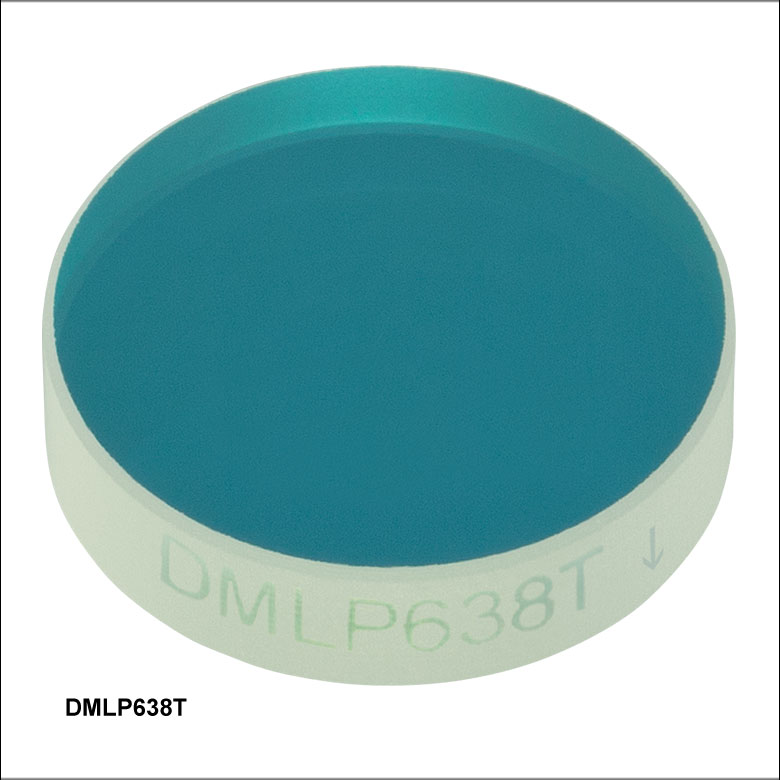
DMLP638
Ø1"
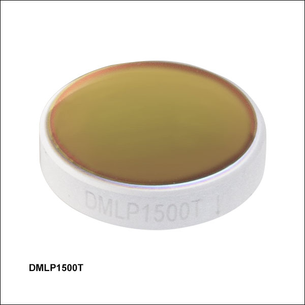
DMLP1800T
Ø1/2"
Application Idea
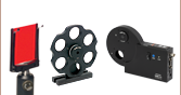
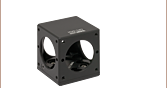
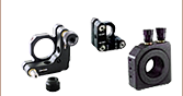
The CM1-DCH Dichroic Cage Cube Holding
a Rectangular Dichroic Mirror
DMBP740B
35 mm x 52 mm


Please Wait
ロングパスダイクロイックミラーのセレクションガイド
(詳細は波長またはグラフ内のバンドをクリック)
| Dichroic Mirrors Selection Guide |
|---|
| Shortpass |
| Longpass |
| Multi-Band |
特長
- ダイクロイックミラーは吸収損失の少ないロングパスフィルタとしても使用可能
- 2つの透過帯域と1つの反射帯域を有するマルチバンドダイクロイックミラーもご用意
- 5種類のサイズから選択可能:Ø12.7 mm(Ø1/2インチ)、Ø25.4 mm(Ø1インチ)、Ø50.8 mm(Ø2インチ)、25 mm x 36 mm、35 mm x 52 mm
- ハードコーティングにより、取扱いやクリーニングが容易
- 紫外線や化学物質に耐性あり
当社のダイクロイックミラー/ビームスプリッタは、波長に応じて光を透過または反射し、スペクトル的に分離します。ロングパスダイクロイックミラーには、カットオン波長を境に透過帯域と反射帯域があります。ロングパス型はカットオン波長よりも短波長側で高い反射率を示し、長波長側で高い透過率を示します。当社ではロングパスミラーとしてご使用いただけるマルチバンドダイクロイックミラーもご用意しております。このダイクロイックミラーにはカットオフ波長とカットオン波長を境に透過帯域が2つ、反射帯域が1つあります。カットオフ波長の短波長側とカットオン波長の長波長側の光に対しては高い透過率を示し、カットオフ波長とカットオン波長の間では高い反射率を示します。
当社では、右のグラフのように425~1800 nmの範囲で様々なカットオン波長のダイクロイックミラーをご提供しています。これらのミラーは45°の入射角で使用するように設計されており、Ø12.7 mm(Ø1/2インチ)、Ø25.4 mm(Ø1インチ)、Ø50.8 mm(Ø2インチ)、25 mm x 36 mm、35 mm x 52 mmの5種類のサイズがございます。 各ミラーの透過率と反射率は下のグラフをご覧ください。
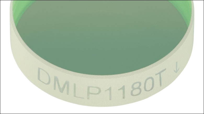
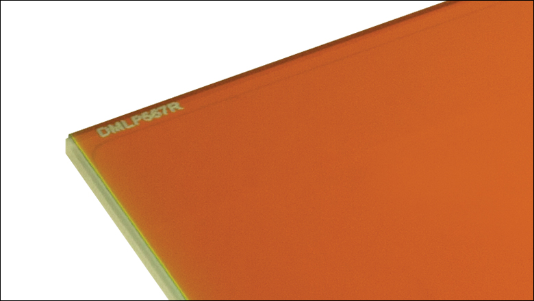
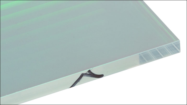
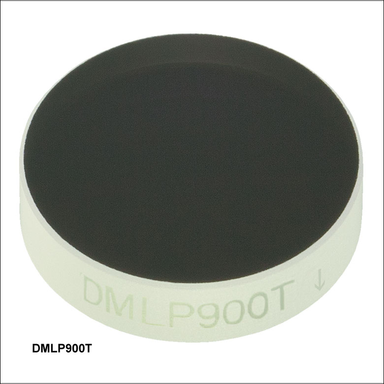
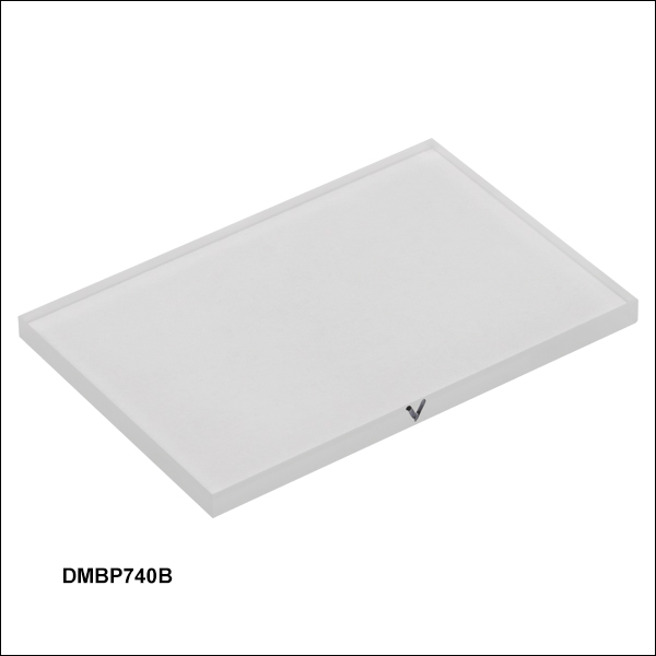
これらの光学素子は一方の面がダイクロイックコーティングされており、その反対側の面は反射防止コーティングがされています。当社ではこのミラーを右上の図に示すような向きで使用することを推奨しています。円形の光学素子の場合は、刻印された矢印がARコーティングされた面を示します。25 mm x 36 mmの長方形の光学素子の場合は、刻印のある面がダイクロイックコーティングされた面です。35 mm x 52 mmのダイクロイックミラーの場合は、側面の山形記号(キャレット)がARコーティング面を指しています。
熱に敏感な実験に対しては、ホットミラーやコールドミラーをご用意しております。またカットオフ波長より長い波長で高い反射率、短い波長で高い透過率を示すショートパスダイクロイックミラーもご用意しております。
用途
「用途」のタブでもご覧いただけるように、これらの光学素子を用いて、カットオン波長よりも短い波長(または波長域)のビームと長い波長(または波長域)のビームを重畳することができます。また、空間的に重畳している異なる波長の光を分離する用途でもお使いいただけます。
蛍光顕微鏡法では、一般にロングパスダイクロイックミラーが利用されています。励起光はダイクロイックミラーによって反射されて対物レンズに入射し、蛍光(励起波長よりも長波長)はダイクロイックミラーを透過してサイエンティフィックカメラ、あるいは光電子増倍管(PMT)に入射します。後方反射光や試料による散乱光などの残留励起光はダイクロイックミラーによって再び反射され、カメラやPMTに入ってスプリアス信号となるのを防止しています。
表面品質と耐久性
このダイクロイックミラー/ビームスプリッタの基板はUV溶融石英で、硬質のイオンビームスパッタリングコーティングが施されています。その結果、動作波長域での優れた透過率、実質的にゼロの自己蛍光、低熱膨張係数といった特性が実現され、紫外域から近赤外域までの使用に適しています。ハードコーティング自体の表面品質(スクラッチ&ディグ)は40-20で、一般的なガラスと同様にクリーニングや取扱いができます。ソフトコーティングと違って、湿度に対する耐性に優れ、強い光照射に対してだけでなく、長期に渡る紫外線への露光に対しても、顕著な劣化や焼き付けを起こしたりすることがありません。これらのフィルタの損傷閾値についての詳細は「損傷閾値」タブをご覧ください。
取付け方法
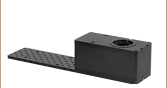
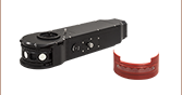
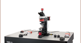
当社では、これらのダイクロイックミラー/ビームスプリッタを顕微鏡用にご使用になるお客様向けに、様々なフィルターキューブやマウントをご用意しております。2ポジションスライダ付きCerna®ブレッドボードトップを用いると、DIY Cerna顕微鏡にに35 mm x 52 mmダイクロイックミラーを取り付けることができます。また25 mm x 36 mmの長方形ダイクロイックミラーは、キネマティックマウントKM2536にも取付けられます。
Click to Enlarge
円形のミラー:刻印された矢印がARコーティング面を示します(詳細は「用途」タブをご覧ください)。


| General Specifications | |||||
|---|---|---|---|---|---|
| Size | Ø1/2" | Ø1" | Ø2" | 25.0 mm x 36.0 mm | 35.0 mm x 52.0 mm |
| Clear Aperture | ≥Ø11.43 mm | ≥Ø22.86 mm | ≥Ø45.72 mm | ≥22.5 mm x 32.4 mm | ≥85%, Elliptical |
| Thickness | 3.2 mm | 3.2 mm | 5.0 mm | 1.0 mm | 2.0 mm (DMLP730B Only) or 3.0 mm |
| Incident Angle | 45° | ||||
| Surface Quality | 40-20 Scratch-Dig | ||||
| Transmitted Wavefront Error | <λ/4 @ 633 nm Over Clear Aperture | ≤λ/4 @ 632.8 nm Over Clear Aperture | |||
| Substrate Material | UV Fused Silicaa | ||||
| Wavelength Specifications | |||||||||
|---|---|---|---|---|---|---|---|---|---|
| Item # Prefix | Cut-On Wavelength | Transmission Band | Absolute Transmission | Average Transmission | Reflection Band | Absolute Reflectance | Average Reflectance | AR Coating Rangea | Damage Threshold |
| DMLP425 | 425 nm | 440 - 800 nm | >85% | >90% | 380 - 410 nm | >90% | >95% | 400 - 800 nm | 1.50 J/cm2 (532 nm, 10 Hz, 10 ns, Ø250 µm) |
| DMLP490 | 490 nm | 505 - 800 nm | >85% | >90% | 380 - 475 nm | >90% | >95% | 400 - 800 nm | 1.00 J/cm2 (532 nm, 10 Hz, 10 ns, Ø538 µm) |
| DMLP505 | 505 nm | 520 - 800 nm | >85% | >90% | 380 - 490 nm | >90% | >95% | 400 - 800 nm | 1.50 J/cm2 (532 nm, 10 Hz, 10 ns, Ø250 µm) |
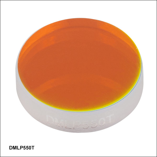
| DMLP550 | 550 nm | 565 - 800 nm | >85% | >90% | 380 - 533 nm | >90% | >95% | 400 - 800 nm | 0.50 J/cm2 (532 nm, 10 Hz, 10 ns, Ø538 µm) |
| DMLP567 | 567 nm | 584 - 800 nm | >85% | >90% | 380 - 550 nm | >90% | >95% | 400 - 800 nm | 1.50 J/cm2 (532 nm, 10 Hz, 10 ns, Ø250 µm) |
| DMLP605 | 605 nm | 620 - 800 nm | >85% | >90% | 470 - 590 nm | >90% | >95% | 400 - 800 nm | 1.50 J/cm2 (532 nm, 10 Hz, 10 ns, Ø250 µm) |
| DMLP638 | 638 nm | 655 - 700 nm | >85% | >90% | 580 - 621 nm | >90% | - | 400 - 800 nm | 1.50 J/cm2 (532 nm, 10 Hz, 10 ns, Ø250 µm) |
| DMLP650 | 650 nm | 685 - 1600 nm | >85% | >90% | 400 - 633 nm | >90% | >95% | 665 - 1600 nm | 0.25 J/cm2 (532 nm, 10 Hz, 10 ns, Ø538 µm) 2.00 J/cm2 (1064 nm, 10 Hz, 10 ns, Ø1.000 mm) |
| DMLP730 | 730 nm | 750 -1100 nm | - | >92% | 450 - 690 nm | - | >97% | 440 - 1800 nm | - |
| 1300 - 1400 nm, 1300 - 1800 nm, 1700 - 1800 nm | - | >94% | |||||||
| DMLP735 | 735 nm | 750 - 1600 nm | - | >93% | 350 - 720 nm | - | >98% | 350 - 1600 nm | - |
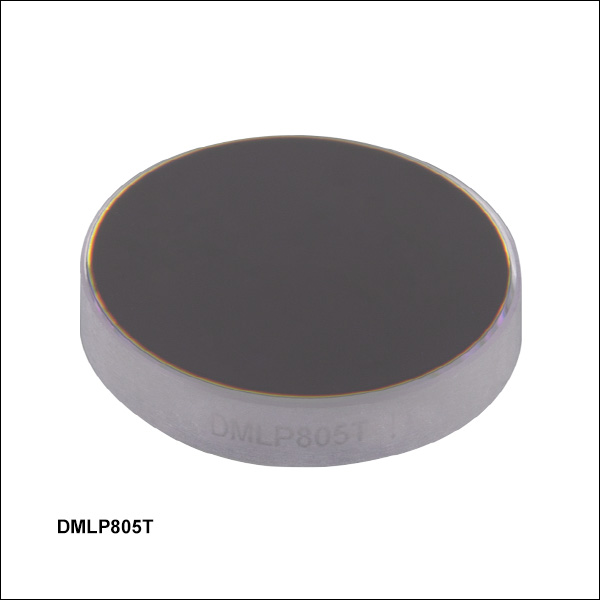
| DMLP805 | 805 nm | 825 - 1300 nm | >85% | >90% | 400 - 785 nm | >90% | >95% | 823 - 1300 nm | - |
| DMLP900 | 900 nm | 932 - 1300 nm | >85% | >90% | 400 - 872 nm | >90% | - | 932 - 1700 nm | 1.00 J/cm2 (532 nm, 10 Hz, 10 ns, Ø250 µm) 6.50 J/cm2 (1064 nm, 10 Hz, 12 ns, Ø250 µm) |
| DMBP740b | 940 nm | 400 - 725 nm, 980 - 1700 nm | - | >93% | 753 - 935 nm | - | >97% | 400 - 1700 nm | - |
| DMLP950 | 950 nm | 990 - 1600 nm | >85% | >90% | 420 - 900 nm | >90% | >95% | 932 - 1700 nm | 1.00 J/cm2 (532 nm, 10 Hz, 10 ns, Ø538 µm) 4.00 J/cm2 (1064 nm, 10 Hz, 10 ns, Ø1.000 mm) |
| DMLP1000 | 1000 nm | 1020 - 1550 nm | >85% | >90% | 520 - 985 nm | >90% | >95% | 1020 - 1550 nm | 0.25 J/cm2 (1064 nm, 10 Hz, 10 ns, Ø459 µm) |
| DMLP1150 | 1150 nm | 1200 - 1900 nm | - | >95% | 720 - 1100 nm | - | >95% | 400 - 1900 nm | - |
| DMLP1180 | 1180 nm | 1260 - 1700 nm | >85% | >90% | 750 - 1100 nm | >90% | >95% | 932 - 1700 nm | 5.00 J/cm2 (1064 nm, 10 Hz, 12 ns, Ø250 µm) |
| DMLP1500 | 1500 nm | 1550 - 2000 nm | >85% | >90% | 1000 - 1450 nm | >90% | >95% | 1550 - 2000 nm | - |
| DMLP1800 | 1800 nm | 1850 - 2100 nm | >85% | >90% | 1500 - 1750 nm | >90% | >95% | 1800 - 2100 nm | 5.00 J/cm2 (2050 nm, 62.5 Hz, 10 ns, Ø348 µm) |
主な用途
- 蛍光顕微鏡
- 異なる波長のビームを結合および分離
- スペクトル成分のフィルタリング
光線の概略図
図1は、ダイクロイックミラー/ビームスプリッタが透過光(青色)を反射光(赤色)を結合している図解です。透過光は光学素子の透過帯域の波長で、反射光は光学素子の反射帯域の波長です。光の伝搬方向が逆の場合は、光学素子はビームスプリッタとなります。図2はその図解です。
いずれの場合においても、結合多色光は、ダイクロイックフィルタのダイクロイックコーティング付きの面側となります。この光学素子の吸収損失を低減するためには、反射波長が基板を透過しないように光学素子の方向を調整することをお勧めします。ダイクロイックミラー/ビームスプリッタが一般のビームスプリッタと異なる点は、強度損失を伴うことなくビームを結合または分離できる点です。
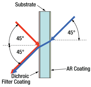
図1: ダイクロイックミラーが異なるスペクトル光を結合
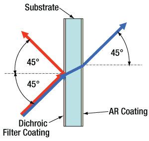
図2: ダイクロイックミラーが異なるスペクトル光に分離
当社のダイクロイックミラー/ビームスプリッタの損傷閾値データ
下の仕様は、当社のダイクロイックミラー/ビームスプリッタの損傷閾値の測定値です。コーティングの種類が同じであればミラーのサイズにかかわらず損傷閾値の仕様は同じです。
| Damage Threshold Specifications | |
|---|---|
| Coating Designation (Item # Prefix) | Damage Threshold |
| DMLP900 | 1.00 J/cm2 (532 nm, 10 Hz, 10 ns, Ø250 µm) 6.50 J/cm2 (1064 nm, 10 Hz, 12 ns, Ø250 µm) |
| DMLP950 | 1.00 J/cm2 (532 nm, 10 Hz, 10 ns, Ø538 µm) 4.00 J/cm2 (1064 nm, 10 Hz, 10 ns, Ø1.000 mm) |
| DMLP1000 | 0.25 J/cm2 (1064 nm, 10 Hz, 10 ns, Ø459 µm) |
| DMLP1180 | 5.00 J/cm2 (1064 nm, 10 Hz, 12 ns, Ø250 µm) |
| DMLP1800 | 5.00 J/cm2 (2050 nm, 62.5 Hz, 10 ns, Ø348 µm) |
| Damage Threshold Specifications | |
|---|---|
| Coating Designation (Item # Prefix) | Damage Threshold |
| DMLP425 | 1.50 J/cm2 (532 nm, 10 Hz, 10 ns, Ø250 µm) |
| DMLP490 | 1.00 J/cm2 (532 nm, 10 Hz, 10 ns, Ø538 µm) |
| DMLP505 | 1.50 J/cm2 (532 nm, 10 Hz, 10 ns, Ø250 µm) |
| DMLP550 | 0.50 J/cm2 (532 nm, 10 Hz, 10 ns, Ø538 µm) |
| DMLP567 | 1.50 J/cm2 (532 nm, 10 Hz, 10 ns, Ø250 µm) |
| DMLP605 | 1.50 J/cm2 (532 nm, 10 Hz, 10 ns, Ø250 µm) |
| DMLP638 | 1.50 J/cm2 (532 nm, 10 Hz, 10 ns, Ø250 µm) |
| DMLP650 | 0.25 J/cm2 (532 nm, 10 Hz, 10 ns, Ø538 µm) 2.00 J/cm2 (1064 nm, 10 Hz, 10 ns, Ø1.000 mm) |
レーザによる損傷閾値について
このチュートリアルでは、レーザ損傷閾値がどのように測定され、使用する用途に適切な光学素子の決定にその値をどのようにご利用いただけるかを総括しています。お客様のアプリケーションにおいて、光学素子を選択する際、光学素子のレーザによる損傷閾値(Laser Induced Damage Threshold :LIDT)を知ることが重要です。光学素子のLIDTはお客様が使用するレーザの種類に大きく依存します。連続(CW)レーザは、通常、吸収(コーティングまたは基板における)によって発生する熱によって損傷を引き起こします。一方、パルスレーザは熱的損傷が起こる前に、光学素子の格子構造から電子が引き剥がされることによって損傷を受けます。ここで示すガイドラインは、室温で新品の光学素子を前提としています(つまり、スクラッチ&ディグ仕様内、表面の汚染がないなど)。光学素子の表面に塵などの粒子が付くと、低い閾値で損傷を受ける可能性があります。そのため、光学素子の表面をきれいで埃のない状態に保つことをお勧めします。光学素子のクリーニングについては「光学素子クリーニングチュートリアル」をご参照ください。
テスト方法
当社のLIDTテストは、ISO/DIS 11254およびISO 21254に準拠しています。
初めに、低パワー/エネルギのビームを光学素子に入射します。その光学素子の10ヶ所に1回ずつ、設定した時間(CW)またはパルス数(決められたprf)、レーザを照射します。レーザを照射した後、倍率約100倍の顕微鏡を用いた検査で確認し、すべての確認できる損傷を調べます。特定のパワー/エネルギで損傷のあった場所の数を記録します。次に、そのパワー/エネルギを増やすか減らすかして、光学素子にさらに10ヶ所レーザを照射します。このプロセスを損傷が観測されるまで繰返します。損傷閾値は、光学素子が損傷に耐える、損傷が起こらない最大のパワー/エネルギになります。1つのミラーBB1-E02の試験結果は以下のようなヒストグラムになります。
上の写真はアルミニウムをコーティングしたミラーでLIDTテストを終えたものです。このテストは、損傷を受ける前のレーザのエネルギは0.43 J/cm2 (1064 nm、10 ns pulse、 10 Hz、Ø1.000 mm)でした。
| Example Test Data | |||
|---|---|---|---|
| Fluence | # of Tested Locations | Locations with Damage | Locations Without Damage |
| 1.50 J/cm2 | 10 | 0 | 10 |
| 1.75 J/cm2 | 10 | 0 | 10 |
| 2.00 J/cm2 | 10 | 0 | 10 |
| 2.25 J/cm2 | 10 | 1 | 9 |
| 3.00 J/cm2 | 10 | 1 | 9 |
| 5.00 J/cm2 | 10 | 9 | 1 |
試験結果によれば、ミラーの損傷閾値は 2.00 J/cm2 (532 nm、10 ns pulse、10 Hz、 Ø0.803 mm)でした。尚、汚れや汚染によって光学素子の損傷閾値は大幅に低減されるため、こちらの試験はクリーンな光学素子で行っています。また、特定のロットのコーティングに対してのみ試験を行った結果ではありますが、当社の損傷閾値の仕様は様々な因子を考慮して、実測した値よりも低めに設定されており、全てのコーティングロットに対して適用されています。
CWレーザと長パルスレーザ
光学素子がCWレーザによって損傷を受けるのは、通常バルク材料がレーザのエネルギを吸収することによって引き起こされる溶解、あるいはAR(反射防止)コーティングのダメージによるものです[1]。1 µsを超える長いパルスレーザについてLIDTを論じる時は、CWレーザと同様に扱うことができます。
パルス長が1 nsと1 µs の間のときは、損傷は吸収、もしくは絶縁破壊のどちらかで発生していると考えることができます(CWとパルスのLIDT両方を調べなければなりません)。吸収は光学素子の固有特性によるものか、表面の不均一性によるものかのどちらかによって起こります。従って、LIDTは製造元の仕様以上の表面の質を有する光学素子にのみ有効です。多くの光学素子は、ハイパワーCWレーザで扱うことができる一方、アクロマティック複レンズのような接合レンズやNDフィルタのような高吸収光学素子は低いCWレーザ損傷閾値になる傾向にあります。このような低い損傷閾値は接着剤や金属コーティングにおける吸収や散乱によるものです。
線形パワー密度におけるLIDTに対するパルス長とスポットサイズ。長パルス~CWでは線形パワー密度はスポットサイズにかかわらず一定です。 このグラフの出典は[1]です。

繰返し周波数(prf)の高いパルスレーザは、光学素子に熱的損傷も引き起こします。この場合は吸収や熱拡散率のような因子が深く関係しており、残念ながらprfの高いレーザが熱的影響によって光学素子に損傷を引き起こす場合の信頼性のあるLIDTを求める方法は確立されておりません。prfの大きいビームでは、平均出力およびピークパワーの両方を等しいCW出力と比較する必要があります。また、非常に透過率の高い材料では、prfが上昇してもLIDTの減少は皆無かそれに近くなります。
ある光学素子の固有のCWレーザの損傷閾値を使う場合には、以下のことを知る必要があります。
- レーザの波長
- ビーム径(1/e2)
- ビームのおおよその強度プロファイル(ガウシアン型など)
- レーザのパワー密度(トータルパワーをビームの強度が1/e2の範囲の面積で割ったもの)
ビームのパワー密度はW/cmの単位で計算します。この条件下では、出力密度はスポットサイズとは無関係になります。つまり、スポットサイズの変化に合わせてLIDTを計算し直す必要がありません(右グラフ参照)。平均線形パワー密度は、下の計算式で算出できます。
ここでは、ビーム強度プロファイルは一定であると仮定しています。次に、ビームがホットスポット、または他の不均一な強度プロファイルの場合を考慮して、おおよその最大パワー密度を計算する必要があります。ご参考までに、ガウシアンビームのときはビームの強度が1/e2の2倍のパワー密度を有します(右下図参照)。
次に、光学素子のLIDTの仕様の最大パワー密度を比較しましょう。損傷閾値の測定波長が光学素子に使用する波長と異なっている場合には、その損傷閾値は適宜補正が必要です。おおよその目安として参考にできるのは、損傷閾値は波長に対して比例関係であるということです。短い波長で使う場合、損傷閾値は低下します(つまり、1310 nmで10 W/cmのLIDTならば、655 nmでは5 W/cmと見積もります)。
この目安は一般的な傾向ですが、LIDTと波長の関係を定量的に示すものではありません。例えば、CW用途では、損傷はコーティングや基板の吸収によってより大きく変化し、必ずしも一般的な傾向通りとはなりません。上記の傾向はLIDT値の目安として参考にしていただけますが、LIDTの仕様波長と異なる場合には当社までお問い合わせください。パワー密度が光学素子の補正済みLIDTよりも小さい場合、この光学素子は目的の用途にご使用いただけます。
当社のウェブ上の損傷閾値の仕様と我々が行った実際の実験の値の間にはある程度の差があります。これはロット間の違いによって発生する誤差を許容するためです。ご要求に応じて、当社は個別の情報やテスト結果の証明書を発行することもできます。損傷解析は、類似した光学素子を用いて行います(お客様の光学素子には損傷は与えません)。試験の費用や所要時間などの詳細は、当社までお問い合わせください。
パルスレーザ
先に述べたように、通常、パルスレーザはCWレーザとは異なるタイプの損傷を光学素子に引き起こします。パルスレーザは損傷を与えるほど光学素子を加熱しませんが、光学素子から電子をひきはがします。残念ながら、お客様のレーザに対して光学素子のLIDTの仕様を照らし合わせることは非常に困難です。パルスレーザのパルス幅に起因する光学素子の損傷には、複数の形態があります。以下の表中のハイライトされた列は当社の仕様のLIDT値が当てはまるパルス幅に対する概要です。
パルス幅が10-9 sより短いパルスについては、当社の仕様のLIDT値と比較することは困難です。この超短パルスでは、多光子アバランシェ電離などのさまざまなメカニクスが損傷機構の主流になります[2]。対照的に、パルス幅が10-7 sと10-4 sの間のパルスは絶縁破壊、または熱的影響により光学素子の損傷を引き起こすと考えられます。これは、光学素子がお客様の用途に適しているかどうかを決定するために、レーザービームに対してCWとパルス両方による損傷閾値を参照しなくてはならないということです。
| Pulse Duration | t < 10-9 s | 10-9 < t < 10-7 s | 10-7 < t < 10-4 s | t > 10-4 s |
|---|---|---|---|---|
| Damage Mechanism | Avalanche Ionization | Dielectric Breakdown | Dielectric Breakdown or Thermal | Thermal |
| Relevant Damage Specification | No Comparison (See Above) | Pulsed | Pulsed and CW | CW |
お客様のパルスレーザに対してLIDTを比較する際は、以下のことを確認いただくことが重要です。
エネルギ密度におけるLIDTに対するパルス長&スポットサイズ。短パルスでは、エネルギ密度はスポットサイズにかかわらず一定です。このグラフの出典は[1]です。
- レーザの波長
- ビームのエネルギ密度(トータルエネルギをビームの強度が1/e2の範囲の面積で割ったもの)
- レーザのパルス幅
- パルスの繰返周波数(prf)
- 実際に使用するビーム径(1/e2 )
- ビームのおおよその強度プロファイル(ガウシアン型など)
ビームのエネルギ密度はJ/cm2の単位で計算します。右のグラフは、短パルス光源には、エネルギ密度が適した測定量であることを示しています。この条件下では、エネルギ密度はスポットサイズとは無関係になります。つまり、スポットサイズの変化に合わせてLIDTを計算し直す必要がありません。ここでは、ビーム強度プロファイルは一定であると仮定しています。ここで、ビームがホットスポット、または他の不均一な強度プロファイルの場合を考慮して、おおよその最大パワー密度を計算する必要があります。ご参考までに、ガウシアンビームのときは一般にビームの強度が1/e2のときの2倍のパワー密度を有します。
次に、光学素子のLIDTの仕様と最大エネルギ密度を比較しましょう。損傷閾値の測定波長が光学素子に使用する波長と異なっている場合には、その損傷閾値は適宜補正が必要です[3]。経験則から、損傷閾値は波長に対して以下のような平方根の関係であるということです。短い波長で使う場合、損傷閾値は低下します(例えば、1064 nmで 1 J/cm2のLIDTならば、532 nmでは0.7 J/cm2と計算されます)。
波長を補正したエネルギ密度を得ました。これを以下のステップで使用します。
ビーム径は損傷閾値を比較する時にも重要です。LIDTがJ/cm2の単位で表される場合、スポットサイズとは無関係になりますが、ビームサイズが大きい場合、LIDTの不一致を引き起こす原因でもある不具合が、より明らかになる傾向があります[4]。ここで示されているデータでは、LIDTの測定には<1 mmのビーム径が用いられています。ビーム径が5 mmよりも大きい場合、前述のようにビームのサイズが大きいほど不具合の影響が大きくなるため、LIDT (J/cm2)はビーム径とは無関係にはなりません。
次に、パルス幅について補正します。パルス幅が長くなるほど、より大きなエネルギに光学素子は耐えることができます。パルス幅が1~100 nsの場合の近似式は以下のようになります。
お客様のレーザのパルス幅をもとに、光学素子の補正されたLIDTを計算するのにこの計算式を使います。お客様の最大エネルギ密度が、この補正したエネルギ密度よりも小さい場合、その光学素子はお客様の用途でご使用いただけます。ご注意いただきたい点は、10-9 s と10-7 sの間のパルスにのみこの計算が使えることです。パルス幅が10-7 sと10-4 sの間の場合には、CWのLIDTも調べなければなりません。
当社のウェブ上の損傷閾値の仕様と我々が行った実際の実験の値の間にはある程度の差があります。これはロット間の違いによって発生する誤差を許容するためです。ご要求に応じて、当社では個別のテスト情報やテスト結果の証明書を発行することも可能です。詳細は、当社までお問い合わせください。
[1] R. M. Wood, Optics and Laser Tech. 29, 517 (1997).
[2] Roger M. Wood, Laser-Induced Damage of Optical Materials (Institute of Physics Publishing, Philadelphia, PA, 2003).
[3] C. W. Carr et al., Phys. Rev. Lett. 91, 127402 (2003).
[4] N. Bloembergen, Appl. Opt. 12, 661 (1973).

レーザーシステムが光学素子に損傷を引き起こすかどうか判断するプロセスを説明するために、レーザによって引き起こされる損傷閾値(LIDT)の計算例をいくつかご紹介します。同様の計算を実行したい場合には、右のボタンをクリックしてください。計算ができるスプレッドシートをダウンロードいただけます。ご使用の際には光学素子のLIDTの値と、レーザーシステムの関連パラメータを緑の枠内に入力してください。スプレッドシートでCWならびにパルスの線形パワー密度、ならびにパルスのエネルギ密度を計算できます。これらの値はスケーリング則に基づいて、光学素子のLIDTの調整スケール値を計算するのに用いられます。計算式はガウシアンビームのプロファイルを想定しているため、ほかのビーム形状(均一ビームなど)には補正係数を導入する必要があります。 LIDTのスケーリング則は経験則に基づいていますので、確度は保証されません。なお、光学素子やコーティングに吸収があると、スペクトル領域によってLIDTが著しく低くなる場合があります。LIDTはパルス幅が1ナノ秒(ns)未満の超短パルスには有効ではありません。
ガウシアンビームの最大強度は均一ビームの約2倍です。
CWレーザの例
波長1319 nm、ビーム径(1/e2)10 mm、パワー0.5 Wのガウシアンビームを生成するCWレーザーシステム想定します。このビームの平均線形パワー密度は、全パワーをビーム径で単純に割ると0.5 W/cmとなります。
しかし、ガウシアンビームの最大パワー密度は均一ビームの約2倍です(右のグラフ参照)。従って、システムのより正確な最大線形パワー密度は1 W/cmとなります。
アクロマティック複レンズAC127-030-CのCW LIDTは、1550 nmでテストされて350 W/cmとされています。CWの損傷閾値は通常レーザ光源の波長に直接スケーリングするため、LIDTの調整値は以下のように求められます。
LIDTの調整値は350 W/cm x (1319 nm / 1550 nm) = 298 W/cmと得られ、計算したレーザーシステムのパワー密度よりも大幅に高いため、この複レンズをこの用途に使用しても安全です。
ナノ秒パルスレーザの例:パルス幅が異なる場合のスケーリング
出力が繰返し周波数10 Hz、波長355 nm、エネルギ1 J、パルス幅2 ns、ビーム径(1/e2)1.9 cmのガウシアンビームであるNd:YAGパルスレーザーシステムを想定します。各パルスの平均エネルギ密度は、パルスエネルギをビームの断面積で割って求めます。
上で説明したように、ガウシアンビームの最大エネルギ密度は平均エネルギ密度の約2倍です。よって、このビームの最大エネルギ密度は約0.7 J/cm2です。
このビームのエネルギ密度を、広帯域誘電体ミラーBB1-E01のLIDT 1 J/cm2、そしてNd:YAGレーザーラインミラーNB1-K08のLIDT 3.5 J/cm2と比較します。LIDTの値は両方とも、波長355 nm、パルス幅10 ns、繰返し周波数10 Hzのレーザで計測しました。従って、より短いパルス幅に対する調整を行う必要があります。 1つ前のタブで説明したようにナノ秒パルスシステムのLIDTは、パルス幅の平方根にスケーリングします:
この調整係数により広帯域誘電体ミラーBB1-E01のLIDTは0.45 J/cm2に、Nd:YAGレーザーラインミラーのLIDTは1.6 J/cm2になり、これらをビームの最大エネルギ密度0.7 J/cm2と比較します。広帯域ミラーはレーザによって損傷を受ける可能性があり、より特化されたレーザーラインミラーがこのシステムには適していることが分かります。
ナノ秒パルスレーザの例:波長が異なる場合のスケーリング
波長1064 nm、繰返し周波数2.5 Hz、パルスエネルギ100 mJ、パルス幅10 ns、ビーム径(1/e2)16 mmのレーザ光を、NDフィルタで減衰させるようなパルスレーザーシステムを想定します。これらの数値からガウシアン出力における最大エネルギ密度は0.1 J/cm2になります。Ø25 mm、OD 1.0の反射型NDフィルタ NDUV10Aの損傷閾値は355 nm、10 nsのパルスにおいて0.05 J/cm2で、同様の吸収型フィルタ NE10Aの損傷閾値は532 nm、10 nsのパルスにおいて10 J/cm2です。1つ前のタブで説明したように光学素子のLIDTは、ナノ秒パルス領域では波長の平方根にスケーリングします。
スケーリングによりLIDTの調整値は反射型フィルタでは0.08 J/cm2、吸収型フィルタでは14 J/cm2となります。このケースでは吸収型フィルタが光学損傷を防ぐには適した選択肢となります。
マイクロ秒パルスレーザの例
パルス幅1 µs、パルスエネルギ150 µJ、繰返し周波数50 kHzで、結果的にデューティーサイクルが5%になるレーザーシステムについて考えてみます。このシステムはCWとパルスレーザの間の領域にあり、どちらのメカニズムでも光学素子に損傷を招く可能性があります。レーザーシステムの安全な動作のためにはCWとパルス両方のLIDTをレーザーシステムの特性と比較する必要があります。
この比較的長いパルス幅のレーザが、波長980 nm、ビーム径(1/e2)12.7 mmのガウシアンビームであった場合、線形パワー密度は5.9 W/cm、1パルスのエネルギ密度は1.2 x 10-4 J/cm2となります。これをポリマーゼロオーダ1/4波長板WPQ10E-980のLIDTと比較してみます。CW放射に対するLIDTは810 nmで5 W/cm、10 nsパルスのLIDTは810 nmで5 J/cm2です。前述同様、光学素子のCW LIDTはレーザ波長と線形にスケーリングするので、CWの調整値は980 nmで6 W/cmとなります。一方でパルスのLIDTはレーザ波長の平方根とパルス幅の平方根にスケーリングしますので、1 µsパルスの980 nmでの調整値は55 J/cm2です。光学素子のパルスのLIDTはパルスレーザのエネルギ密度よりはるかに大きいので、個々のパルスが波長板を損傷することはありません。しかしレーザの平均線形パワー密度が大きいため、高出力CWビームのように光学素子に熱的損傷を引き起こす可能性があります。
| Posted Comments: | |
隆憲 舟橋
(posted 2024-06-04 18:06:43.297) いつもお世話になります。
今、ダイクロイックミラーのDMLP490Tを使用していますが、520nmの透過光の偏波方向が変わってしまっているみたいです。このようなことはあるのでしょうか?また、偏波方向が変わらないようにするには、どのようにすればよろしいでしょうか?
まだ、反射側の確認はしていませんが、反射側の偏波方向が変わることはあるでしょうか? cdolbashian
(posted 2024-06-18 09:28:43.0) Thank you for reaching out to us with your inquiry. You are asking about some observed ellipticity in an initially polarized beam, after interacting with this dichroic mirror. Unfortunately, this is expected due to the nature of the dielectric coating stack which forms the active layers of this mirror. I have contacted you directly to discuss your experimental requirements and possible solutions therein. Francesco Scazza
(posted 2024-03-27 10:49:03.027) Is it possible to know the surface flatness for these dichroic beamsplitters, i.e. the RWE? Thanks cdolbashian
(posted 2024-03-29 02:46:25.0) Thank you for reaching out to us with this inquiry. As these are high stress coatings, we would estimate an integer number of waves for the RWE, typically in the range of 4-5. user
(posted 2023-11-01 09:36:00.593) Is it possible to get a DMLP490R in a larger size than listed on the standard products? For example, a 50 mm by 70 mm rectangle, or an even larger rectangle such as 100 mm by 140 mm? How large could Thorlabs produce these dichroic mirrors? jpolaris
(posted 2023-11-02 02:42:21.0) Thank you for contacting Thorlabs. Request for customizations such as larger versions of our stock optics can be made by emailing us at techsupport@thorlabs.com. I have reached out to you directly to discuss the feasibility of this request. Kimhan Tan
(posted 2023-08-10 15:00:16.75) Hi Thorlab team, I am using DMLP1180 dichroic mirror to reflect the green light (530nm), and transmit both Red light (633nm) and IR (1310nm). As per checked in the DMLP1180 raw data. The green light (530nm) has Reflectivity: 78.8%, red light (633nm) has Transmitivity: 67.2%, and IR (1310nm) has trasminitivity: 98.2%.
My inquiry is, is there any other replacement to have better reflectivity on the green light (530nm) and better transmitivity on the red light (633nm) while maintaining IR trasmitivity?
Thanks cdolbashian
(posted 2023-08-16 11:51:03.0) Thank you for reaching out to us with this inquiry. Unfortunately, we do not have such a dichroic mirror available which will have optimal performance at all wavelengths of interest. For future product selection inquiries, please feel free to email techsupport@thorlabs.com user
(posted 2023-07-27 14:51:11.31) Dear Madam or Sir,
We are using your dichroic longpass filter for fluorescence imaging.
Fluorescent light is transmitted into an APD. I am measuring a change in transmission loss from about 3 to 6 percent.
Setup 650 nm laser, polarised.
Filter aligned 45 degrees +- 1.5 degrees.
Light is sent AGAINST the normal direction of operation.
In the test, I am changing the AOI by about 1 mrad and measure the transmitted power. I observe the mentioned change in transmission.
Is this to be expected?
Sincerely
Clemens Schäfermeier cdolbashian
(posted 2023-08-16 10:56:07.0) Thank you for reaching out to us with this inquiry! I have contacted you directly with some troubleshooting steps in order to diagnose the behavior you are seeing. Felipe Pinto
(posted 2023-06-12 11:50:42.157) Hello,
I intend to use this mirror with a high power laser, which generates optical power up to 30 Watts.
This mirror is capable to handle such high optical power level?
Best regards, jpolaris
(posted 2023-06-13 02:32:14.0) Thank you for contacting Thorlabs. We do not yet have comprehensive data for CW damage thresholds. I have reached out to you to gather more information about your source and to discuss the feasibility of using DMLP1180 in your application. DAEHOON KIM
(posted 2023-03-16 10:41:23.847) hello. My name is Daehoon Kim from LG Electronics in Korea.
I am interested in 'Longpass Dichroic Mirrors/Beamsplitters: 425 nm Cut-On Wavelength' among your products.
Is it possible to purchase products in other sizes besides commercial ones? A size larger than the DMLP425R is required. For example, about 50x72 mm in size (double the size), etc.
I look forward to hearing from you. jdelia
(posted 2023-03-23 09:38:41.0) Thank you for contacting Thorlabs. I have contacted you directly to discuss the feasibility of this custom item request. Prashanth Koundinya
(posted 2023-01-30 16:49:08.317) Hello,
We are noticing some light specs on the filter coating surfcae where it seems that the coating is damaged or corroded after some time when there is exposure to normal atmosphere.
Does the filter come with any protective coating? If not, can such a coating be applied at source?
Thanks jgreschler
(posted 2023-02-02 04:06:54.0) Thank you for reaching out to Thorlabs. The coating itself is not reactive to atmosphere, I've reached out to you directly to discuss some other possibilities for this damage. Giulio Maria Rossi
(posted 2023-01-06 16:43:20.713) Good Afternoon,
would it be possible to have the group delay (or spectral phase) data over the reflection range in the DMLP950 filter?
Thanks! cdolbashian
(posted 2023-01-23 03:03:31.0) Thank you for reaching out to us with this inquiry Giulio! I have contacted you directly to share these data. Derek Decker
(posted 2022-10-27 11:54:00.27) You should consider expanding your dichroic beam splitters out to 12 or even 20 microns. Other people are doing this and so should you. For example, you will find a long pass and a short pass out to 12um on this page: https://ispoptics.com/product-category/ir-beamsplitters/ cdolbashian
(posted 2022-10-31 01:32:06.0) Thank you for the feedback Derek! Juriy Hastanin
(posted 2022-09-28 14:29:37.873) Hi,
My optical bench involves two CW (continues waves) lasers of 1 W with the beam diameter about of 1 mm.
So, I selected for my optical setup the dichroic Long-Pass mirror ‘DMLP638’ (to combine two laser wavelengths: 600 nm and 675 nm)
However, I don’t found the data on the Laser Induced Damage Threshold for CW.
The Data Sheet for this mirror, published on your website, specifies only the Laser Induced Damage Threshold measured for a pulsed laser (10 Hz, 10 ns, 532 nm, Ø250 µm).
Could you please check, if the selected mirror can operate without damage for the specified laser power density or/and specify LIDT measured for CW (order of magnitude)?
Could you verify if the selected mirror %% (or )
Thank you in advance
PhD J.Hastanin cdolbashian
(posted 2022-10-14 03:16:05.0) Thank you for reaching out to us with this inquiry Juriy. While we do not have a specific damage threshold, as we have not done extensive testing with these components, we have had reports of customers in the past successfully using these with lasers which had 7W of power with beam diameters between 1-2 mm. zhang bo
(posted 2022-09-07 04:41:26.553) HI what is the reflectivity of the DLMP900 at 808nm and the refractive index at 1064nm . thank you very much cdolbashian
(posted 2022-09-26 04:46:44.0) Thank you for reaching out to us. The reflectivity data can be found on the overview tab by clicking the blue "i" next to any of the product part numbers. In this case, the reflectivity value is ~99.8% for unpolarized light. Other polarization states' reflectivity data can be found as I described above. user
(posted 2022-07-19 20:30:02.033) 你好,光路中有810nm和405nm的激光,我想过滤掉810nm的激光而保留405nm的激光,使用DMLP425长通二向色镜可以吗,如果不行的话应该用哪个型号呢? Chaman Gupta
(posted 2022-07-08 16:25:08.197) What is the antireflection coating made of and what wavelengths does it cover for this 950 nm cut-on long-pass filter?
I am using a CW 1070 nm laser and getting two reflected laser spots from the 950 LP filter. I am using the filter in the recommended orientation, but have tried other orientations as well, and the problem persists. cdolbashian
(posted 2022-07-19 11:44:21.0) Thank you for reaching out to us with this inquiry Chaman. It seems like you are experiencing a ghosted reflection from the back surface of the dichroic mirror. I have contacted you directly to troubleshoot this issue. jingtao dong
(posted 2022-06-21 10:13:41.157) I need long-pass dichroic mirrors reflecting at 532 nm and transmitting at 633 nm while maintaining the polarization of the input beam (e.g., linearly polarized beam). Could you please suggest a mirror for that? cdolbashian
(posted 2022-06-24 02:45:33.0) Thank you for reaching out to us with this inquiry. Looking at our availability of dichroics, I think the DMLP567 would be a good fit for you. The graphs on the page above show the performance of this light with S- and P- polarized light. victor argueta
(posted 2022-03-17 13:59:48.723) HI there,
Do you have any suggestions on how to clean a dichronic mirror that has some fingerprints on it? cdolbashian
(posted 2022-03-25 08:44:31.0) Thank you for reaching out to us Victor. Cleaning these dichroic mirrors should be done with the same care that you would use on any of our dielectric-coated optics. We have a nice guide here: https://www.thorlabs.com/newgrouppage9.cfm?objectgroup_ID=9025 user
(posted 2021-11-17 10:20:30.897) We use the dichroic mirror in reflection mode, what would be the reflected wavefront error over 5mm dia spot ? jgreschler
(posted 2021-11-18 09:12:45.0) Thank you for reaching out to Thorlabs. Unfortunately, we don't have a formal spec for the wavefront distortion for the reflected beam for these filters. For a more detailed response you can reference YLohia's answer to Ricardo Am{ezquita-Orozco on 2021-08-27 02:43:30.0 in the Feedback tab of this product page. Michele Cotrufo
(posted 2021-07-15 11:23:17.3) Hi, I am interested in the model DMLP1180 and I need to work with circularly polarized beams (for both inputs). Do you know if/how the beamsplitter will affect the circular polarization of the inputs? YLohia
(posted 2021-07-15 01:26:51.0) Hello, thank you for contacting Thorlabs. Since these dichroic mirrors have dielectric coatings, there will be some impact on the polarization upon reflection. I have reached out to you directly with a theoretical simulation of the phase shift induced by the optic. John McGuire
(posted 2021-06-29 10:26:15.683) Can you provide any information on the dispersion on reflection of the DMLP950? YLohia
(posted 2021-08-27 02:43:30.0) Hello John, thank you for contacting Thorlabs. What wavelength(s) are you interested in this information for? I had reached out to you at the time of your original post, but I never heard back. If you're still interested in this information, please email your local Thorlabs Tech Support group (in your case, techsupport-cn@thorlabs.com) and we would be happy to assist. Ricardo Am{ezquita-Orozco
(posted 2021-02-11 08:21:35.033) Cold you provide the wave distortion for the reflected beam of the DMLP490 or the DMLP505? YLohia
(posted 2021-03-15 03:00:35.0) Thank you for contacting Thorlabs. Unfortunately, we don't have a formal spec for the wavefront distortion for the reflected beam for these filters. The dichroics utilize a high-stress IBS coating, which will result in a reflected wavefront error of >5-6 waves. The reflected image quality will be quite poor. For this reason, it's usually best practice to use the reflected beam path solely as an illumination path. That being said, we have been working on a lower stress coating process and we may be able to offer a custom version (though we are still working to characterize and formalize the RWE specs). If interested, please email techsupport@thorlabs.com. Mauro Melozzi
(posted 2020-11-27 05:25:52.957) Dear Sirs
is it possible to ask for the Zemax encrypted file of cichroic coatings?
regards
maur melozzi YLohia
(posted 2020-12-02 10:14:41.0) Hello Maur, thank you for contacting Thorlabs. I have reached out to you directly with an encrypted coating file. Danni Ma
(posted 2020-09-23 17:44:31.14) Is there a mirror that can split and combine the laser beams of 1200nm and 2400nm? If not, can you customize it? Thank you in advance. YLohia
(posted 2020-09-23 09:20:27.0) Hello, thank you for contacting Thorlabs. Unfortunately, we do not currently offer a dichroic mirror that can split 1200 nm and 2400 nm. Custom optics can be requested by emailing Tech Support at techsupport@thorlabs.com or by clicking the "Request Quote" button above. We will reach out to you directly to discuss the possibility of offering this. Sajid Hussain
(posted 2020-07-15 02:14:32.897) Hi,
Does the dichroic surface has any effect on the polarization of the incident light ? YLohia
(posted 2020-07-15 11:23:14.0) Hello, thank you for contacting Thorlabs. Yes, these dichroic optics do affect the polarization of the input beam since the coating is made of dielectric stacks. Ilya R.
(posted 2020-06-09 13:05:50.6) Are you able to custom fabricate a dichroic mirror on a ZnSe substrate? Essentially, I need a plate similar to
BSW711, but with coating reflective for visible and anti-reflective in the wavelength region around 10.6 um. YLohia
(posted 2020-06-09 02:08:06.0) Thank you for contacting Thorlabs. Custom optics can be requested by emailing us at techsupport@thorlabs.com. I have reached out to you directly to discuss the possibility of offering this. Mikael Malmström
(posted 2020-04-10 11:40:08.76) Could you please provide me with the reflectivity data of the DMLP900 coating if used under 0° AOI (I want to block 532)? Thanks in advance/M YLohia
(posted 2020-04-10 12:01:39.0) Thank you for contacting Thorlabs. We expect the reflection at 0 deg AOI for 532 nm to be roughly around 99.76%. I have reached out to you directly with this data. Mathieu Perrin
(posted 2020-02-14 15:38:30.603) I think the legend is wrong for the R/T graph for P-pol. R and T spectra have been exchanged at least on the DMLP1500 series and DMLP1800 series of dichroic mirror. llamb
(posted 2020-02-20 10:47:02.0) Thank you very much for bringing this to our attention. We will have these two P-Pol. graphs updated with the correct legends. Sebastian de Echaniz
(posted 2020-01-30 10:21:11.477) What is the surface flatness for these dichroic mirrors? nbayconich
(posted 2020-02-13 10:59:37.0) Thank you for contacting Thorlabs. I will reach out to you directly with more information regarding our dichroic mirror specifications. Vincent Jarlaud
(posted 2019-04-10 11:16:59.797) By how much can the cut-on wavelength be shifted with angle tuning ? I'm interested in particular in the DMLP1800. YLohia
(posted 2019-04-29 10:13:23.0) Hello, based on our direct discussion regarding your application, an AOI of 55-60 degrees on the DMLP1800 will shift the cut-on wavelength such that you obtain a high transmission at 1762 nm and a high reflection at 1550 nm. t.ding
(posted 2019-03-10 11:30:35.763) we are interested in this type of dichro mirror and wonder can the size be customised to 26*38mm? The purpose is to fit it into the Olympus Fluorescence Mirror unit.
Thanks. YLohia
(posted 2019-04-05 03:13:03.0) Hello, thank you for contacting Thorlabs. We have been in touch with you
regarding this since the original posting. Special items can be requested by emailing techsupport@thorlabs.com / clicking the red "Request Quote" button above. lukas.tenbrake
(posted 2018-06-29 10:19:02.74) Hi, could you please provide me with the reflectance data for the DMLP605 for AOI close to 0 degrees? Thanks in advance. YLohia
(posted 2018-07-03 10:13:42.0) Hello, I have reached out to you directly with that data. kaushilade2007
(posted 2018-05-24 05:17:55.263) it is possible to reflected around 785nm light and below 785 light transmitted both side.
We want use double filter turret. below turret use for 785 nm and above turret use for fluo filter aroun 532 so the laser which is coming from above turret can be tranmitted to below turret mirror should be transmitted both side.
Please suggest mirror for the that. YLohia
(posted 2018-05-24 11:39:31.0) Hello, I tried reaching you at the email provided by you to clarify a few things but it bounced back due to a typo. Please send us an email at techsupport@thorlabs.com if you would like to discuss this further. avi.barak
(posted 2017-12-17 03:19:12.983) Is there a chance of getting Longpass mirror at the LWIR range.
specifically 10. 5 micron? nbayconich
(posted 2017-12-21 10:00:33.0) Thank you for contacting Thorlabs. I will reach out to you directly to discuss our custom capabilities. At the moment we do not have plans to release an MIR dichroic product as a stock option. lc0616
(posted 2017-08-08 16:53:07.527) Hi, I wonder what will happen if the incident angle of the light changes.
Thanks a lot for your help. tfrisch
(posted 2017-08-16 05:02:24.0) Hello, thank you for contacting Thorlabs. Angle tuning is a common use for dielectric filters. As the angle of incidence increases, the cutoff wavelength will shift to shorter wavelengths, and the there will be some distortion of the curve. I will reach out to you with more details. steinfo2
(posted 2017-05-30 13:20:54.57) Could you please provide reflectance and transmission data for the DMLP650R for 0 degrees AOI? Thank you in advance. nbayconich
(posted 2017-06-13 01:23:02.0) Thank you for contacting Thorlabs. I will reach out to you directly with more information on the reflectivity and transmission of the DMLP650R. yoav.romach
(posted 2016-09-07 18:46:59.71) There is large gap in the wavelengths at the near IR: You have filters up to 650nm but than only from 900nm+.
Filters around 750 would be very useful, we are currently using ones from another company. tfrisch
(posted 2016-09-08 09:52:59.0) Hello, thank you for contacting Thorlabs. You may be interested in our Hot and Cold Mirrors. I will contact you with more details. sebastien.tempone-wiltshire
(posted 2016-07-26 08:38:11.747) Could you please provide me with the reflectivity data of the DMLP900 coating if used under 0° AOI (Range: 600-1100nm)? Thanks in advance. simon.holzberger
(posted 2016-03-31 10:09:10.42) Could you please provide me with the reflectivity data of the DMLP650 coating if used under 0° AOI (Range: 600-1500nm)? Thanks in advance. besembeson
(posted 2016-03-31 10:47:14.0) Response from Bweh at Thorlabs USA: I have contacted you with example theoretical data for zero degrees AOI for a close DMLP series. There will be a significant shifts in the transmission and reflection bands compared to the 45 deg AOI design specifications. ornik.jan
(posted 2016-02-08 18:19:22.74) Dear Thorlabs,
I am using DMLP425 dichroic mirror in my setup. By mistake I firstly mounted it in an incorrect way, so that the IR coating was facing the wrong way (flipped by 180°). However, this surprisingly delivered better results for my application than the results when the dichroic mirror is placed correctly. Therefore I would kindly ask you to provide me with transmission and reflection data for incorrectly mounted mirror (at 45° to incident light). If not, could you provide me with the data about the thickness and refractive index of the substrate and the AR coating(s), so that I can recalculate transmission?
Best regards,
Jan besembeson
(posted 2016-02-11 09:16:49.0) Response from Bweh at Thorlabs USA: I would expect the transmission to be identical regardless of the orientation but the reflection, due to the (small) thickness of the substrate and possibly the size/position of your detector could change. The substrate material is fused silica and the thickness is 3.2mm. The refractive index and thickness of coating information is proprietary. I will contact you to get details about the better results you mentioned above. k.h.sheikh
(posted 2016-02-05 13:23:42.197) What is the approximate thickness of the dichroic coating ? besembeson
(posted 2016-02-11 09:14:02.0) Response from Bweh at Thorlabs USA: Thanks for contacting Thorlabs. This information is proprietary at this time. wim.weltjens
(posted 2015-09-30 10:05:14.59) Dear,
Is it possible to extend the range of the filter to 1700nm?
Thanks in advance,
Wim besembeson
(posted 2015-10-08 01:41:28.0) Response from Bweh at Thorlabs USA: Thanks for contacting Thorlabs. We are not able to provide these at different wavelengths at this time. We will consider this wavelength when we expand our offerings in the future. ries
(posted 2015-03-17 11:56:16.643) What is the reflected wavefront error for the dichroics? Or alternatively the surface flatness in lambda over the whole filter? This would be a very important parameter for many applications. Also, I assume it is different for the different substrates, so it would be useful to be able to compare them.
Thanks a lot! besembeson
(posted 2015-03-27 10:55:56.0) Response from Bweh at Thorlabs USA: We will contact you by email regarding this data. g.moussu
(posted 2015-03-17 09:55:36.323) Hello, I'm looking for a dichroic beamsplitter cube with a cut-off wavelenght around 480nm. I want it in a cube to avoid the shift between the input and the output beams. Is it possible to make such a product ? Best regards, Gabrielle besembeson
(posted 2015-03-26 04:01:23.0) Response from Bweh at Thorlabs USA: I will followup with you by email regarding quoting this please. fabian1.langer
(posted 2015-02-02 09:37:30.117) Hello, I am interested in dichroic beamsplitters with a cut-off wavelength at 1300 nm. How diffucult is it to get a beamsplitter with a performance like the DMSP1180 but with the cut-off wavelength shifted upward by about 100 nm?
Best, Fabian besembeson
(posted 2015-02-03 01:00:31.0) Response from Bweh at Thorlabs USA: At this time, we are not able to provide these dichroic beamsplitters at other wavelengths. One alternative to consider is an edgepass filter used at an angle of incidence different from normal incidence which will shift the cut-off to lower wavelengths. For example the FEL1400 (http://www.thorlabs.us/thorproduct.cfm?partnumber=FEL1400). 1982ariel
(posted 2015-01-27 13:47:43.347) Please specify CW damage threshold.
Please specify data in W\cm as in other products jlow
(posted 2015-01-28 04:04:52.0) Response from Jeremy at Thorlabs: We do not have the CW damage threshold data for the dichroic beamsplitters yet. We are looking to have this tested and we will post the damage threshold data once it is available. jennifer.suen
(posted 2014-06-26 15:14:57.553) Hello,i see the features introduction that"On round optics, an engraved arrow points toward the surface with the AR coating",but for the first time i see the chinese features"对于圆形的波片,所刻箭头所指的表面镀有反射薄膜;对于矩形波片,有刻纹的表面镀有二向薄膜。在两种类型中,二向薄膜表面的反面都镀有增透膜。",so i'd like to know what the direction of the engraved arrow is antireflection coating or flection coating?Maybe there are three coating?dichroic coating,antireflection coating or flection coating? Regards, Jennifer . jlow
(posted 2014-07-30 05:23:01.0) Response from Jeremy at Thorlabs: On round optics, an engraved arrow points toward the surface with the AR coating; on rectangular optics, the side with the engraving has the dichroic coating. We will be work on correcting the translation on the Chinese webpage. Thank you for bringing this to our attention. carlos.macias
(posted 2014-03-31 12:17:13.347) Hello, Do you know if the DMLP900R produces second harmonic when illuminated with 1030 nm? We need a dichroic mirror to transmit (or reflect) highly efficiently (and pol independent) the visible range while reflecting (or transmitting) 1030 nm, without producing second harmonic. We dont mind sacrificing 1030 nm. Any suggestions? besembeson
(posted 2014-04-03 08:02:22.0) Response from Bweh E at Thorlabs: These coatings are centrosymmetric so there is no second harmonic generation. The DMSP1000R might be a better option for your application though. We have data on the website that shows the transmission and reflection for P- and S- polarization states to determine how suitable these are for your application. emeyersc
(posted 2014-03-03 15:39:46.777) I just bought a DMSP1500 and DMLP900, neither of which has an engraved arrow. I guess the AR coating side looks like a dielectric stack and the dichroic side looks like a mirror? Which is the preferred incidence side for beam combining and which for beam splitting? jlow
(posted 2014-03-04 08:07:25.0) Response from Jeremy at Thorlabs: The preferred incident side for both cases are depicted in the Applications tab on this page. The side that looks like a front surface mirror would be the dichroic side. c.alpmann
(posted 2014-02-27 15:52:08.717) I am looking for a rectangular DC mirror to homogeneously / equally reflect circularly and radially polarized laser light at 532nm to be used in a microscope filter cube in combination with white light illumination. In the specs of DMLP605R the reflectance for S- and P-polarized light seems to be "equall" but is this true for all polarization states? jlow
(posted 2014-03-13 04:28:39.0) Response from Jeremy at Thorlabs: This should be similar for other polarization states as well. slarin
(posted 2014-02-19 06:16:23.19) Hi there, need a filter to cut 1550 and transmit 1680 nm. Can I use DMLP1800T on different AOI to move cutoff margin for my application? jlow
(posted 2014-02-27 04:29:49.0) Response from Jeremy at Thorlabs: You can angle tune the dichroic slightly. The slope, transmission and reflection amount can change slightly though. The 1500nm version might be better for you in this case. I will contact you to provide more details. roland.bege
(posted 2013-11-29 06:44:23.453) Hello. I'd like to build in the mirrow at the highest reflection rate which is for s-polarized light for DMLP900. How do I know the s- and p-polarization of the mirrow due to the arrow?
Thanks Roland cdaly
(posted 2013-12-05 09:43:10.0) Response from Chris at Thorlabs: The arrow on the DMLP900 points to the side with the anti-reflection coating. The other side will have the dichroic beams splitter coating on it, which is he recommended incidence side for splitting. S and P polarization are completely dependent on the orientation of the beam with respect to the optic. If you were to imagine you had a horizontal beam going into an optic at a normal angle of incidence, there would be no S or P. If you then turn the optic about the vertical axis, the light polarized vertically would be considered s-polarized and light polarized horizontally would be considered p-polarized. If you were to have rotated the optic about the horizontal axis instead, they would be reversed. s.kovalev
(posted 2013-08-12 09:45:30.203) Hello. Do you have reflection and transmission datas for the DMLP567 at wavelengths from 800nm to 1550nm. With best regards Sergey. sharrell
(posted 2013-08-12 16:32:00.0) Response from Sean at Thorlabs: We are in the process of acquiring this data for the DMLP567, and I will post it to the website and email it to you directly tomorrow. We will also scan our other products from 200 - 2600 nm, and I'll post the data as it becomes available. s.kovalev
(posted 2013-08-08 16:35:59.583) We are looking for dichroic mirrors to separate 0.5um from both 0.8 and 1.3 um, like reflection 500nm, transmission – 800 and 1300 nm, or inverse.
In the list of list of dichroic mirrors didn’t found mirrors with it specs.
What dichroic mirrors are suitable for it? cdaly
(posted 2013-08-15 16:09:00.0) Response from Chris at Thorlabs: Thank you for using our feedback tool. Unfortunately, there is no dichroic mirror which we offer that can separate these wavelengths in the desired way. The cold mirror M254C00 or M254C45 appears to have the closest type of T/R curves which would allow for this. fabian.luecking
(posted 2013-06-18 09:29:04.387) Hello,
How do these filters perform when used at an AOI of zero? Is the behaviour comparable to that of other multilayer filters, i.e., do the entire transmission characteristics shift towards shorter wavelengths?
Regards,
Fabian tcohen
(posted 2013-06-19 17:48:00.0) Response from Tim at Thorlabs to Fabian: As you decrease from 45deg to lower angles of incidence, your spectra will shift to longer wavelengths. Typically there can also be deformations with this large of an AOI change. user
(posted 2013-05-20 13:44:34.08) Hi, Do you have reflection and transmission data for the DMLP1800 filter at wavelengths between 1100 and 1500 nm? tcohen
(posted 2013-08-05 11:08:00.0) Response from Tim at Thorlabs: Thank you for contacting us. We are typically able to provide out of band performance data on request. As out of band data is not as rigorously monitored in QC, performance can vary with coating lots, especially in out of band wavelengths where the part may be fluctuating or on a slope. I see you did not leave any contact information, but we can offer representative data as well as scans specific to a product ordered by contacting us at techsupport@thorlabs.com. rakhoury
(posted 2013-02-28 18:58:31.1) HI, I'm interested in the DMLP567 but I need to transmit above 1100nm and it's not clear from the plot provided. Can you send me an extended transmission plot or does this need to be custom made? tcohen
(posted 2013-03-06 14:50:00.0) Response from Tim at Thorlabs: Thank you for contacting us. One out of band scan (45deg %Tavg) we have taken on the DMLP567 showed ~57.4%T at 1100nm growing to ~89.7%T at 1200nm. We do not QC for this out of band wavelength and performance may vary from lot to lot. Perhaps a cold mirror such as the M254C45 may be appropriate for your application. I will contact you directly to discuss your T/R and wavelength requirements. tcohen
(posted 2013-01-17 15:13:00.0) Response from Tim at Thorlabs: Thank you for your inquiry. We will test a DMSP1000 out to 2000nm and I will contact you to keep you updated. As an alternative, typical DMSP1500 transmission is ~50% at 670nm and has >90%R at 2000nm. jlow
(posted 2013-01-15 19:24:00.0) Response from Jeremy at Thorlabs: We will e-mail you the extended transmission plot directly. cm476
(posted 2013-01-14 23:47:18.36) Hi,
For the longpass dichroic DMLP567, could you send me an extended transmission plot please? It would be nice to be able to estimate the strength of spectral components in the 850-1000nm region.
Best regards,
Clemens g9622513
(posted 2013-01-14 10:05:04.22) We require a dichronic mirror with HT at 670 nm and R>80% at 2000 nm. Could you please tell us the reflectivity of DMSP1000 at 2000 nm? jlow
(posted 2012-09-28 09:24:00.0) Response from Jeremy at Thorlabs: The DMLP1800 will have around 57% reflectivity at 632.8nm. I will get in contact with you directly regarding the reflectivity graph for the DMLP1800. lylee_heu
(posted 2012-09-22 04:13:00.0) Hello,I need a Dichronic Mirror, with high Transmission (or reflection) at 1.9um band and Reflection (or transmission) at 632.8nm wavelength, to combine the both laser beams. The data for the DMLP1800 does not show the information at 632.8nm. Could I know this data at 632.8nm? Or can you make a dichronic mirror/beamsplitter to meet our requirement? Thanks very much for your assistance. Sincerly, L. Li tcohen
(posted 2012-08-15 10:02:00.0) Response from Tim at Thorlabs to Maria: Thank you for contacting us. The DMLP505 specifications include the 380-490nm reflection band and the 520-700nm transmission bands. Outside performance can vary more from lot to lot as this is not the primary focus during coating. That being said, we will send you some typical data and discuss your transmission requirements to find the best solution for you. For your interest, we also offer a service for sending a tested transmission data sheet for a specific part upon purchase. This will give you exact calibration for the part you receive and dispel any concerns about lot to lot variance. mtibb075
(posted 2012-08-09 15:54:47.0) Hello,
I am looking for a Dichronic Mirror/beamsplitter that relfects under 505nm, but transmitts a 1092nm wavelength. The data for the DMLP505 does not show if it transmitts or reflects at the 1092nm wavelength. I was wondering if I could know this data, or if a dichronic mirror/beamsplitter can be made to do this.
Thank you for your help in advance.
Sincerly,
Maria Tibbo jlow
(posted 2012-08-09 15:53:00.0) Response from Jeremy at Thorlabs: This would be a custom coating that we could possibly do. I will contact you directly to discuss this in more detail. rcorrea
(posted 2012-08-02 18:39:25.0) Hi there, Is it possible to get the DMSP1000L filter with the transmission/reflection regions switched? i.e. have the dichroic reflect below 1000 nm, and transmit for wavelengths greater than 1000 nm (at 45 degrees AOI). Thanks! tcohen
(posted 2012-06-21 11:53:00.0) Response from Tim at Thorlabs: Thank you for your feedback! We are currently looking into the possibility of extending our elliptical optics line and we are grateful for your time in sharing your interest with us! In the meantime, we may be able to offer this as a custom and I will contact you directly to discuss the required specifications of the coating and substrate and to discuss our coating schedule. shaun.johnstone
(posted 2012-06-20 00:47:30.0) The option of 2" elliptical dichroics would be extremely useful for my application. They could be mounted in KCB2E mounts and used to combine larger beams with the easy alignment of a cage system. sharrell
(posted 2012-04-18 08:59:00.0) Response from Sean at Thorlabs to yingk0917: Thank you for your feedback! It appears that you were viewing the data from www.thorlabschina.cn, and there was an error with the file stored on that site. We will work to get the link updated on our Chinese site, and I will email you the correct file directly. I apologize for the inconvenience. yingk0917
(posted 2012-04-17 22:35:51.0) Can you give me the specific reflectivity and transmissivity data of DML900. The data on the website is not useful. Thank you. tcohen
(posted 2012-04-05 11:36:00.0) Response from Tim at Thorlabs: Thank you for your feedback. Our closest stock match would be the DMLP567. I have contacted you with an extended curve for evaluation as well as information on a custom coating. jaber
(posted 2012-03-29 16:23:28.0) Need to separate blue and IR with thin dichroic mirror. Blue is 473 nm, IR is 785 nm but we need a range of 785nm up to a minimum of 930 nm (more range if we can get it) to pick up Raman peaks. Do we need a special coating?
Prefer reflection of the blue, transmission of the IR, but can go the other way. tcohen
(posted 2012-03-28 15:43:00.0) Response from Tim at Thorlabs: Thank you for your feedback! Our closest stock match would be a shortpass, DMSP805, centered at 805nm. However, we may be able to offer a custom coating. I will contact you with more information. valya
(posted 2012-03-27 11:43:53.0) Hi! Can you recommend an image quality dichroic mirror for 45 aoi, transmission below ~700 nm, reflection above ~700 nm? Thanks! tcohen
(posted 2012-02-28 11:00:00.0) Response from Tim at Thorlabs: Thank you for your feedback on the DMLP1180. I have contacted you directly with the data out to 2100nm. malo.de-kersauson
(posted 2012-02-28 09:05:41.0) Hi, I need a 1500-2100 transmission window with a minimun 1100 cutoff wavelength. Do you have the specs for the DMLP1180 between 1800 and 2100 ? lmorgus
(posted 2011-10-11 14:44:00.0) Response from Laurie at Thorlabs to jact: Thank you for your feedback. I've spoken with one of the engineers in our optics group, and they will use their spectrophotometer to determine the s and p transmissions for these filters. We will post that data to our website as soon as it becomes available. jact
(posted 2011-10-11 15:32:24.0) Like one of your other posters I would like to see the curves as regards s and p-pol reflection/transmission, in this instance for the DMLP505 and DMLP567 dichroics. jjurado
(posted 2011-08-30 15:51:00.0) Response from Javier at Thorlabs to last poster: please contact us at techsupport@thorlabs.com so that we can provide this information for you. user
(posted 2011-08-30 12:00:07.0) Hello, I need reflecting spectrum of 1180R filter in visible band (400nm to 750nm). Do you have an extended reflection Band plot in visible range ? jjurado
(posted 2011-06-27 15:18:00.0) Response from Javier at Thorlabs to sbouvier: Thank you very much for contacting us. The marking on the side of our dichroic beamsplitters indicates the dichroic side. sbouvier
(posted 2011-06-24 12:12:10.0) How to distinguish AR coating than Dichroic Filter
Coating ? There is a black mark on one side, wich one ?
Regards Customer Email: sbouvier@evosens.fr This customer would like to be contacted. jjurado
(posted 2011-05-13 17:39:00.0) Response from Javier at Thorlabs to volker.t.sonnenschein: Thank you very much for contacting us. The transmission of the DMLP567 dichroic mirror/beamsplitter decays very rapidly after 850nm, so it will most likely not be suitable for your application. I will send you an extended transmission plot shortly. I will also research some alternatives and let you know. volker.t.sonnenschein
(posted 2011-05-13 13:38:39.0) Is there Reflection/Transmission data available above 800nm for this Dichroic filter: DMLP567L
We plan to use it as wavelength separator for the funamental/second harmonic of a Ti:sa laser (700-1000nm) jjurado
(posted 2011-04-04 10:47:00.0) Response from Javier at Thorlabs to seydi: Thank you very much for your feedback. At the moment, we do not have a dichroic mirror/beasmplitter that meets your specifications, and manufacturing one from scratch would not be cost effective at all. However, I will share your comments with our optics engineers and let you know if we decide to develop a solution that would be suitable for your application. I will contact you directly for further assistance. seydi
(posted 2011-04-02 03:09:27.0) Would it be possible to produce a short-pass rectangular dichroic filter at 900 or 950nm cutoff wavelenth and transmissive at all visible range? Actually DMSP1000R is also suitable for me but there will be problem when imaging blue fluorescence since its transmission is reducing below 520nm wavelength... jjurado
(posted 2011-03-29 14:47:00.0) Response from Javier at Thorlabs to al.dhalla: Thank you very much for submitting your request. I will discuss the possibility of developing a dichroic mirror/beamsplitter suitable for your application with our optics department. I will contact you shortly. al.dhalla
(posted 2011-03-29 11:24:12.0) Would it be possible to fabricate a dichroic with a 50/50 point at 950nm? I think this would be very useful for systems that employ broadband light in the 840nm and 1060nm ranges. The 900nm dichroic is a little too close to 840 for our application. jjurado
(posted 2011-03-29 10:03:00.0) Response from Javier at Thorlabs to gmp1g09: Thank you very much for submitting your request. We currently do not carry a long pass dichroic mirror/beamsplitter that meets your requirements. However, I will contact you directly to discuss other possible alternatives for your application. gmp1g09
(posted 2011-03-28 15:24:51.0) I was wondering if youve got a longpass dichroic mirror from about 900-1000nm to at least 1800nm ... jjurado
(posted 2011-03-21 14:06:00.0) Response from Javier at Thorlabs to cek1: Thank you for contacting us with your request. You can access plots with transmission data in Excel format for each dichroic beamsplitter through the "Download Plot Data" link next to the transmission vs. wavelength graph. I will send you the data for the transmission of the s and p polarization components directly. cek1
(posted 2011-03-21 18:03:29.0) You have curves of wavelength versus average Reflection and Transmission at 45-degree angle-of-incidence. Do you have the data for the individual polarizations (often called s-polarization and p-polarization) as well? Greg
(posted 2011-01-13 08:16:07.0) A response from Greg at Thorlabs to phamdt: Unfortunately we do not currently offer a dichroic mirror designed to reflect 248 nm. If you do not need a wavelength separation optic, the NB1-H03 may be suitable for you. phamdt
(posted 2010-12-21 13:25:42.0) I am a gradute student working on a laser-related project. I am looking for a dichroic mirror that will reflect wavelengths at 248 nm. Do you have a product that matches my needs? tor
(posted 2010-12-03 16:35:40.0) Response from Tor at Thorlabs to jnichols: Thank you for your request. Unfortunately, customized dichroic beamsplitters are often difficult to provide. I will contact you so we can explore cost-effective, alternate solutions. jnichols
(posted 2010-12-03 13:22:06.0) Do you have the capability to make dichroic beamsplitters for extended range regions, such as the 8-12 um LWIR band? gilad-d1
(posted 2010-10-11 17:46:23.0) is it possible to reverse the reflection/transmission order?
I.e. to reflect the long Vis (425-700 nm) wavelength and transmit the short wavelength (350-425) in custom made dichroic filter? Adam
(posted 2010-05-14 08:19:58.0) A response from Adam at Thorlabs to Sheehy: We currently do not damage threshold information for these mirrors. We can send these out for testing but would like to contact you first. We would like to know the powers you are using and the wavelengths that would be of interest. sheehy
(posted 2010-05-13 15:05:16.0) it would be useful to know optical damage thresholds for these dichroic mirrors klee
(posted 2009-09-08 17:09:55.0) A response from Ken at Thorlabs to jorge: Thank you for your valuable feedback. Your suggestion has been forwarded to our optics division. jorge
(posted 2009-09-04 09:15:20.0) Dichroic beamsplitters, both 0 and 45 degrees, with 900nm cut-off wavelength would be very useful for those who work with diode lasers together with Nd:YAG lasers (reflection band of, for instance, 400-900nm, transmission band 900-1300nm, and viceversa).
Thanks for your attention. |

 ズーム
ズーム
Click to Enlarge
200~2500 nmのデータはこちらからダウンロードいただけます。
グラフの網掛け領域は仕様に記載されている性能を保証する透過帯
と反射帯を示しています。この領域以外の性能についてはロット毎に
異なり、保証されません。
| Specifications | |
|---|---|
| Cut-On Wavelength | 425 nm |
| Transmission Band (Tabs > 85%, Tavg > 90%) | 440 - 800 nm |
| Reflection Band (Rabs > 90%, Ravg > 95%) | 380 - 410 nm |
| Item # | More Info |
| DMLP425T | |
| DMLP425 | |
| DMLP425L | |
| DMLP425R | |

 ズーム
ズーム
Click to Enlarge
300~2600 nmの生データ こちらからダウンロードいただけます。
グラフの網掛け領域は仕様に記載されている性能を保証する透過帯
と反射帯を示しています。この領域以外の性能についてはロット毎に
異なり、保証されません。
| Specifications | |
|---|---|
| Cut-On Wavelength | 490 nm |
| Transmission Band (Tabs > 85%, Tavg > 90%) | 505 - 800 nm |
| Reflection Band (Rabs > 90%, Ravg > 95%) | 380 - 475 nm |
| Item # | More Info |
| DMLP490T | |
| DMLP490 | |
| DMLP490L | |
| DMLP490R | |

 ズーム
ズーム
Click to Enlarge
250~2500 nmの生データはこちらからダウンロードいただけます。
グラフの網掛け領域は仕様に記載されている性能を保証する透過帯
と反射帯を示しています。この領域以外の性能についてはロット毎に
異なり、保証されません。
| Specifications | |
|---|---|
| Cut-On Wavelength | 505 nm |
| Transmission Band (Tabs > 85%, Tavg > 90%) | 520 - 800 nm |
| Reflection Band (Rabs > 90%, Ravg > 95%) | 380 - 490 nm |
| Item # | More Info |
| DMLP505T | |
| DMLP505 | |
| DMLP505L | |
| DMLP505R | |

 ズーム
ズーム
Click to Enlarge
300~2600 nmの生データはこちらからダウンロードいただけます。
グラフの網掛け領域は仕様に記載されている性能を保証する透過帯
と反射帯を示しています。この領域以外の性能についてはロット毎に
異なり、保証されません。
| Specifications | |
|---|---|
| Cut-On Wavelength | 550 nm |
| Transmission Band (Tabs > 85%, Tavg > 90%) | 565 - 800 nm |
| Reflection Band (Rabs > 90%, Ravg > 95%) | 380 - 533 nm |
| Item # | More Info |
| DMLP550T | |
| DMLP550 | |
| DMLP550L | |
| DMLP550R | |

 ズーム
ズーム
Click to Enlarge
200~2600 nmの生データはこちらからダウンロードいただけます。
グラフの網掛け領域は仕様に記載されている性能を保証する透過帯
と反射帯を示しています。この領域以外の性能についてはロット毎に
異なり、保証されません。
| Specifications | |
|---|---|
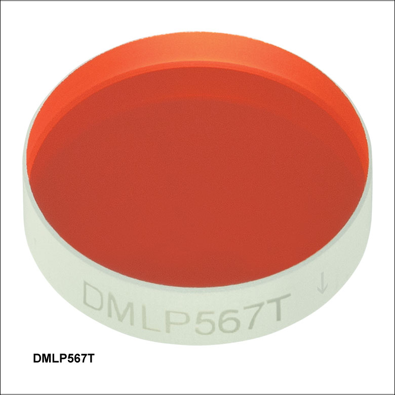
| Cut-On Wavelength | 567 nm |
| Transmission Band (Tabs > 85%, Tavg > 90%) | 584 - 800 nm |
| Reflection Band (Rabs > 90%, Ravg > 95%) | 380 - 550 nm |
| Item # | More Info |
| DMLP567T | |
| DMLP567 | |
| DMLP567L | |
| DMLP567R | |

 ズーム
ズーム
Click to Enlarge
200~2600 nmのデータはこちらからダウンロードいただけます。
グラフの網掛け領域は仕様に記載されている性能を保証する透過帯
と反射帯を示しています。この領域以外の性能についてはロット毎に
異なり、保証されません。
| Specifications | |
|---|---|
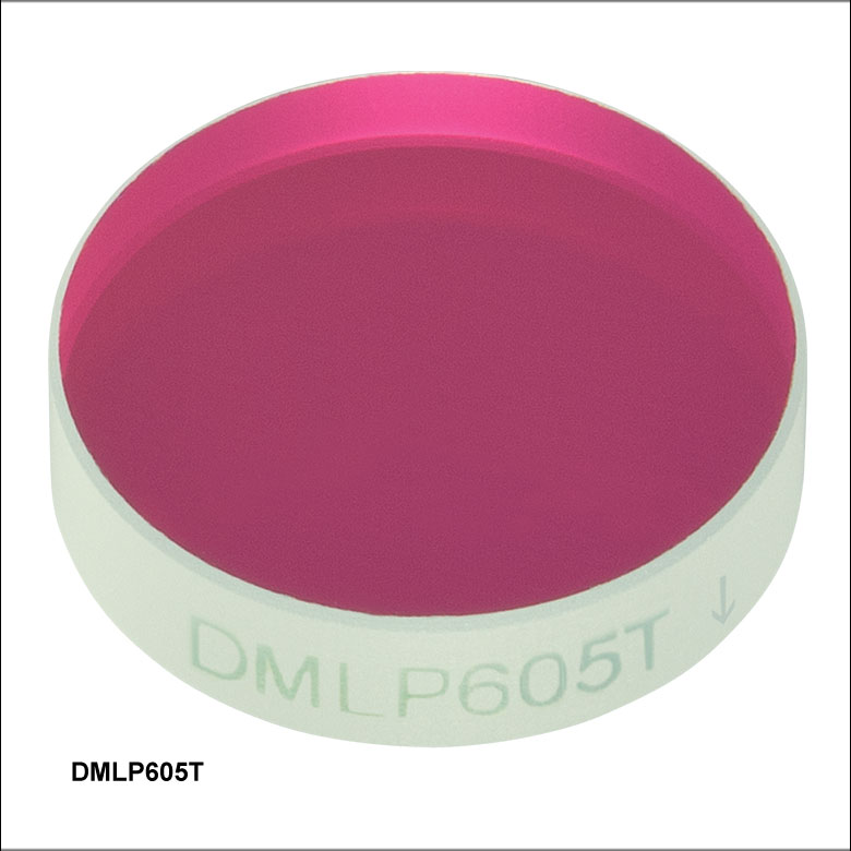
| Cut-On Wavelength | 605 nm |
| Transmission Band (Tabs > 85%, Tavg > 90%) | 620 - 800 nm |
| Reflection Band (Rabs > 90%, Ravg > 95%) | 470 - 590 nm |
| Item # | More Info |
| DMLP605T | |
| DMLP605 | |
| DMLP605L | |
| DMLP605R | |

 ズーム
ズーム
Click to Enlarge
200~2600 nmのデータはこちらからダウンロードいただけます。
グラフの網掛け領域は仕様に記載されている性能を保証する透過帯
と反射帯を示しています。この領域以外の性能についてはロット毎に
異なり、保証されません。
| Specifications | |
|---|---|
| Cut-On Wavelength | 638 nm |
| Transmission Band (Tabs > 85%, Tavg > 90%) | 655 - 700 nm |
| Reflection Band (Rabs > 90%) | 580 - 621 nm |
| Item # | More Info |
| DMLP638T | |
| DMLP638 | |
| DMLP638L | |
| DMLP638R | |

 ズーム
ズーム
Click to Enlarge
300~2600 nmのデータはこちらからダウンロードいただけます。
グラフの網掛け領域は仕様に記載されている性能を保証する透過帯
と反射帯を示しています。この領域以外の性能についてはロット毎に
異なり、保証されません。
| Specifications | |
|---|---|
| Cut-On Wavelength | 650 nm |
| Transmission Band (Tabs > 85%, Tavg > 90%) | 685 - 1600 nm |
| Reflection Band (Rabs > 90%, Ravg > 95%) | 400 - 633 nm |
| Item # | More Info |
| DMLP650T | |
| DMLP650 | |
| DMLP650L | |
| DMLP650R | |

 ズーム
ズーム
Click to Enlarge
250~2500 nmの生データはこちらからダウンロードいただけます。
グラフの網掛け領域は仕様に記載されている性能を保証する透過帯と反射帯を示しています。この領域以外の性能についてはロット毎に異なり、 保証されません。
| Specifications | |
|---|---|
| Cut-On Wavelength | 730 nm |
| Transmission Band (Tavg > 92%) | 750 - 1100 nm |
| Transmission Band (Tavg > 94%) | 1300 - 1400 nm, 1300 - 1800 nm, 1700 - 1800 nm |
| Reflection Band (Ravg > 97%) | 450 - 690 nm |
| Item # | More Info |
| DMLP730B | |

 ズーム
ズーム
Click to Enlarge
250~2500 nmの生データはこちらからダウンロードいただけます。
グラフの網掛け領域は仕様に記載されている性能を保証する透過帯と反射帯を示しています。この領域以外の性能についてはロット毎に異なり、
保証されません。
| Specifications | |
|---|---|
| Cut-On Wavelength | 735 nm |
| Transmission Band (Tavg > 93%) | 750 - 1600 nm |
| Reflection Band (Ravg > 98%) | 350 - 720 nm |
| Item # | More Info |
| DMLP735B | |

 ズーム
ズーム
Click to Enlarge
250~2500 nmの生データはこちらからダウンロードいただけます。
グラフの網掛け領域は仕様に記載されている性能を保証する透過帯
と反射帯を示しています。この領域以外の性能についてはロット毎に
異なり、保証されません。
| Specifications | |
|---|---|
| Cut-On Wavelength | 805 nm |
| Transmission Band (Tabs > 85%, Tavg > 90%) | 825 - 1300 nm |
| Reflection Band (Rabs > 90%, Ravg > 95%) | 400 - 785 nm |
| Item # | More Info |
| DMLP805T | |
| DMLP805 | |
| DMLP805L | |
| DMLP805R | |

 ズーム
ズーム
Click to Enlarge
200~2600 nmの生データはこちらからダウンロードいただけます。
グラフの網掛け領域は仕様に記載されている性能を保証する透過帯
と反射帯を示しています。この領域以外の性能についてはロット毎に
異なり、保証されません。
| Specifications | |
|---|---|
| Cut-On Wavelength | 900 nm |
| Transmission Band (Tabs > 85%, Tavg > 90%) | 932 - 1300 nm |
| Reflection Band (Rabs > 90%) | 400 - 872 nm |
| Item # | More Info |
| DMLP900T | |
| DMLP900 | |
| DMLP900L | |
| DMLP900R | |

 ズーム
ズーム
Click to Enlarge
250~2500 nmの生データはこちらからダウンロードいただけます。
グラフの網掛け領域は仕様に記載されている性能を保証する透過帯
と反射帯を示しています。この領域以外の性能についてはロット毎に
異なり、保証されません。
| Specifications | |
|---|---|
| Cutoff Wavelength | 740 nm |
| Cut-On Wavelength | 940 nm |
| Transmission Bands (Tavg > 93%) | 400 - 725 nm, 980 - 1700 nm |
| Reflection Band (Ravg > 97%) | 753 - 935 nm |
| Item # | More Info |
| DMBP740B | |

 ズーム
ズーム
Click to Enlarge
300~2600 nmの生データはこちらからダウンロードいただけます。
グラフの網掛け領域は仕様に記載されている性能を保証する透過帯
と反射帯を示しています。この領域以外の性能についてはロット毎に
異なり、保証されません。
| Specifications | |
|---|---|
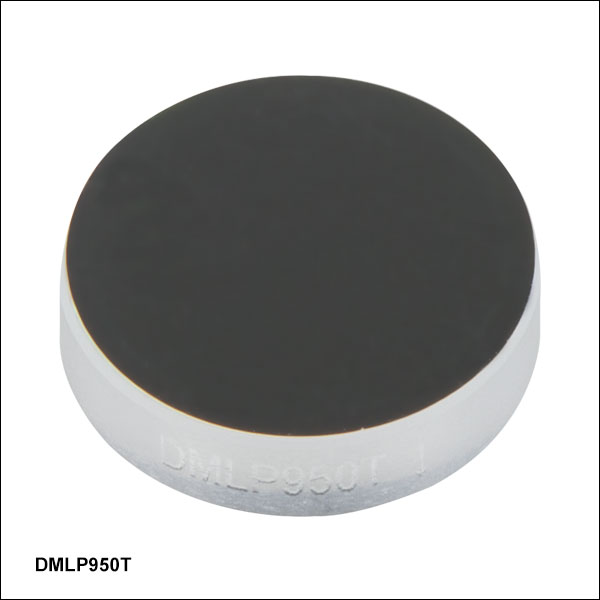
| Cut-On Wavelength | 950 nm |
| Transmission Band (Tabs > 85%, Tavg > 90%) | 990 - 1600 nm |
| Reflection Band (Rabs > 90%, Ravg > 95%) | 420 - 900 nm |
| Item # | More Info |
| DMLP950T | |
| DMLP950 | |
| DMLP950L | |
| DMLP950R | |

 ズーム
ズーム
Click to Enlarge
250~2500 nmのデータはこちらからダウンロードいただけます。
グラフの網掛け領域は仕様に記載されている性能を保証する透過帯
と反射帯を示しています。この領域以外の性能についてはロット毎に
異なり、保証されません。
| Specifications | |
|---|---|
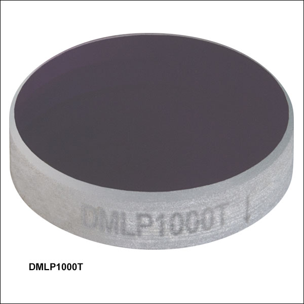
| Cut-On Wavelength | 1000 nm |
| Transmission Band (Tabs > 85%, Tavg > 90%) | 1020 - 1550 nm |
| Reflection Band (Rabs > 90%, Ravg > 95%) | 520 - 985 nm |
| Item # | More Info |
| DMLP1000T | |
| DMLP1000 | |
| DMLP1000L | |
| DMLP1000R | |

 ズーム
ズーム
Click to Enlarge
250~2500 nmの生データはこちらからダウンロードいただけます。
グラフの網掛け領域は仕様に記載されている性能を保証する透過帯と反射帯を示しています。この領域以外の性能についてはロット毎に異なり、
保証されません。
| Specifications | |
|---|---|
| Cut-On Wavelength | 1150 nm |
| Transmission Band (Tavg > 95%) | 1200 - 1900 nm |
| Reflection Band (Ravg > 95%) | 720 - 1100 nm |
| Item # | More Info |
| DMLP1150B | |

 ズーム
ズーム
Click to Enlarge
200~2600 nmのデータはこちらからダウンロードいただけます。
グラフの網掛け領域は仕様に記載されている性能を保証する透過帯
と反射帯を示しています。この領域以外の性能についてはロット毎に
異なり、保証されません。
| Specifications | |
|---|---|
| Cut-On Wavelength | 1180 nm |
| Transmission Band (Tabs > 85%, Tavg > 90%) | 1260 - 1700 nm |
| Reflection Band (Rabs > 90%, Ravg >95%) | 750 - 1100 nm |
| Item # | More Info |
| DMLP1180T | |
| DMLP1180 | |
| DMLP1180L | |
| DMLP1180R | |

 ズーム
ズーム
Click to Enlarge
250~2500 nmの生データはこちらからダウンロードいただけます。
グラフの網掛け領域は仕様に記載されている性能を保証する透過帯と
反射帯を示しています。この領域以外の性能についてはロット毎に
異なり、保証されません。
| Specifications | |
|---|---|
| Cut-On Wavelength | 1500 nm |
| Transmission Band (Tabs > 85%, Tavg > 90%) | 1550 - 2000 nm |
| Reflection Band (Rabs > 90%, Ravg > 95%) | 1000 - 1450 nm |
| Item # | More Info |
| DMLP1500T | |
| DMLP1500 | |
| DMLP1500L | |
| DMLP1500R | |

 ズーム
ズーム
Click to Enlarge
250~2500 nmのデータはこちらからダウンロードいただけます。
グラフの網掛け領域は仕様に記載されている性能を保証する透過帯と
反射帯を示しています。この領域以外の性能についてはロット毎に
異なり、保証されません。
| Specifications | |
|---|---|
| Cut-On Wavelength | 1800 nm |
| Transmission Band (Tabs > 85%, Tavg > 90%) | 1850 - 2100 nm |
| Reflection Band (Rabs > 90%, Ravg > 95%) | 1500 - 1750 nm |
| Item # | More Info |
| DMLP1800T | |
| DMLP1800 | |
| DMLP1800L | |
| DMLP1800R | |