 Products Home
ナノ粒子フィルム型直線偏光子

- UV, Visible, NIR, and IR Spectral Ranges
- Unmounted and Mounted Versions
- Extinction Ratios Up to 100 000:1
- Laser Damage Thresholds Up to 25 W/cm2
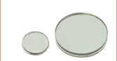
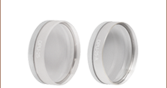
Unmounted Linear Polarizers
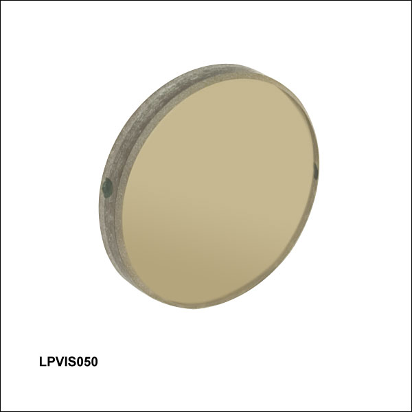
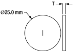
LPVIS100
(Ø25.0 mm)
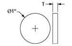
LPUV050
(Ø12.5 mm)
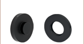
LPUV050-MP2
(SM05 Compatible)
LPNIRD100-MP2
(SM1 Compatible)
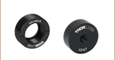
Mounted Linear
Polarizer in
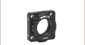
RSP1X15 Indexed
Rotation Mount
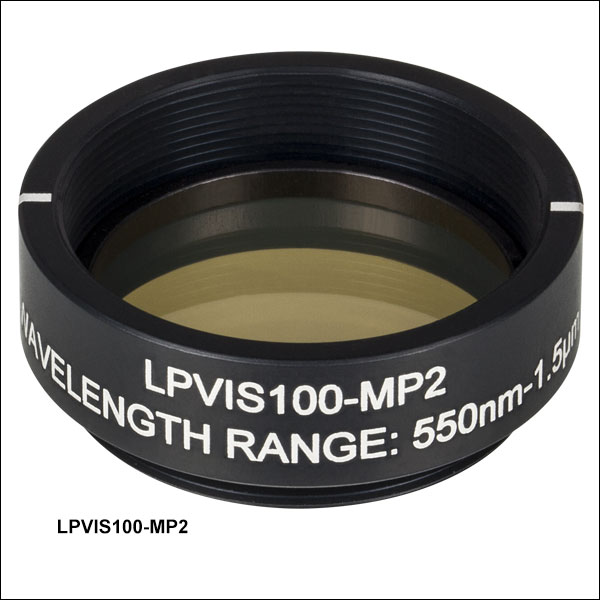
Mounted Linear Polarizers


Please Wait
| Table 1.1 Linear Polarizer Selection Guide | ||||
|---|---|---|---|---|
| Item # Prefix | Wavelength Range | Extinction Ratio Grapha | Laser Damage Thresholdb | |
| Unmounted | Mounted | |||
| LPUV | 365 - 395 nm | 1 W/cm2 Continuous Blockc 5 W/cm2 Continuous Passc | 10 W/cm2 Continuous Block 25 W/cm2 Continuous Pass | |
| LPVISA | 480 - 550 nm | |||
| LPVISC | 510 - 800 nm | |||
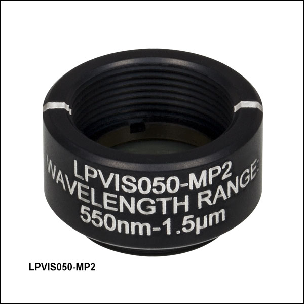
| LPVIS | 550 nm - 1.50 µm | |||
| LPNIR | 650 nm - 2.00 µm | |||
| LPNIRB | 650 nm - 1.10 µm | 10 W/cm2 Continuous Blockd 25 W/cm2 Continuous Passd | ||
| LPNIRA | 1.00 - 3.00 µm | |||
| LPNIRC | 1.10 - 1.80 µm | |||
| LPNIRD | 1.26 - 1.36 µm | |||
| LPNIRF | 1.50 - 1.60 µm | |||
| LPMIR | 1.50 - 5.00 µm | |||
特長
- 高い偏波消光比とレーザ損傷閾値(Table G1.1~G8.1を参照)
- 高消光比、低消光比の2タイプ:
- LPUV、LPVISA、LPVISC、LPVIS、LPNIR、LPNIRA、LPNIRD、LPNIRF、LPMIRから始まる型番:高消光比、Ø12.5 mmまたはØ25.0 mm
- LPNIRB、LPNIRCから始まる型番:低消光比、Ø12.7 mmまたはØ25.4 mm
- マウント無し、もしくはSMネジ切加工付きマウント付き
- マウント無し直線偏光子LPNIRB、LPNIRC、LPNIRD、LPNIRFシリーズは、それぞれの波長範囲においてフラットなスペクトル応答を示します。
- マウント無しタイプには保護用ガラス基板が付いたバージョンあり(型番:LPNIRB、LPNIRA、LPNIRC、LPNIRD、 LPNIRF、LPMIRを除く)
- UV光や化学物質に対する耐性あり
- サイズや波長のカスタマイズにも対応(詳細は当社までお問合せください)。
このナノ粒子フィルム型直線偏光子には、偏光効果を生み出すためにソーダガラスに埋め込まれた長楕円形のナノ粒子が使われています。偏光子の透過軸は、マウント無しの偏光子(LPNIRA、LPNIRD、LPNIRF、LPMIRを除く)にはエッジに2つの黒い印で示されています。また、マウント付きの偏光子には筐体に白い線で刻印されています。
ナノ粒子偏光子は、従来のポリマーベースの偏光子よりも優れた性能を有しています。低価格版の偏光子もナノ粒子偏光子も、透過軸に対して垂直に偏光された光を吸収しますが、ナノ微粒子のほうがはるかに高い損傷閾値と広い動作温度範囲を示します。LPUV、LPVISA、LPVISC、LPVIS、LPNIR、LPMIRシリーズのすべての偏光子は非常に高い消光比を示しますが、波長依存性は大きくなります(対応可能な波長範囲内)。それに比べてLPNIRB、LPNIRA、LPNIRC、LPNIRD、LPNIRFシリーズの偏光子は高い透過率で、消光比は低いながらも波長依存性も比較的小さくなります(対応可能な波長範囲)。性能を比較するには「仕様」および「グラフ」タブ、そしてTable 1.1をご覧ください。
超薄型の偏光子LPNIRDとLPNIRFシリーズは、ARコーティング付き(入射角0°、動作波長範囲においてRavg< 0.25%)で、1310 nmと1550 nmの通信波長におけるより狭い波長域でより高いレベルの透過率が得られます。 厚さが90 μmしかないため、光学素子にダメージを与えないよう、当社では、オプトメカニクス部品にこれらの偏光子を取り付ける際には、低応力固定リング(SM05LTRRやSM1LTRR)のご使用をお勧めします。
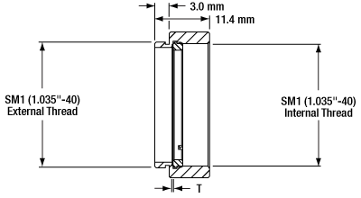
マウント付きの偏光子の筐体にはSM05外ネジやSM1外ネジが付いており、ケージシステムやレンズチューブなどのSMネジ切加工付きの部品に簡単に組み込むことができます。また、マウント付きの偏光子は回転マウントに簡単に取り付けることができ、回転調整が容易に行なうことができます。
マウント無し偏光子(LPNIRB、LPNIRA、LPNIRC、LPNIRD、LPNIRF、LPMIRシリーズを除く)は、ソーダガラスの薄い層でできていて、強度を上げるために屈折率を整合した2枚のガラス基板(Schott Glass B270)の間に挟まれています。こちらの偏光子を取り付ける際には注意が必要です。過剰に機械的応力を付加すると消光比が大幅に低下する場合があります。マウント付き偏光子、およびLPNIRA、LPNIRB、LPNIRC、LPNIRD、LPNIRF、LPMIRシリーズのマウント無し偏光子は、高い損傷閾値を得るためにガラス基板には挟まれていません。厚さ0.09 mm~0.55 mmの薄いソーダガラス製偏光子のみで構成されています。そのため、取扱いにはより注意が必要ですが、標準の光学製品のクリーニング法や溶剤を使用できます。
| Item # Prefix | LPUVa | LPVISAa | LPVISCa | LPVISa | |
|---|---|---|---|---|---|
| Wavelength Range | 365 - 395 nm | 480 - 550 nm | 510 - 800 nm | 550 - 1500 nm | |
| Extinction Ratio Bandsb | |||||
| > 100 000 : 1 | 372 - 388 nm | - | 530 - 640 nm | 600 - 1200 nm | |
| > 10 000 : 1 | 369 - 390 nm | 480 - 550 nm | 520 - 740 nm | 550 - 1500 nm | |
| > 1000 : 1 | 365 - 395 nm | - | 510 - 800 nm | - | |
| > 200:1 | - | - | - | - | |
| General Specifications | |||||
| Polarizer Material | Nanoparticles in Sodium-Silicate Glass | ||||
| Substrate Material | Unmounted | Schott Glass B270 | |||
| Mounted | None | ||||
| Optic Diameter | Ø12.5 mm (Ø0.49") or Ø25.0 mm (Ø0.98") | ||||
| Optic Diameter Tolerance | ±0.2 mm (0.008") | ||||
| Optic Thickness | Unmounted | 2.0 ± 0.2 mm | |||
| Mounted | 220 ± 50 µm | 280 ± 50 µm | 280 ± 50 µm | 260 ± 50 µm | |
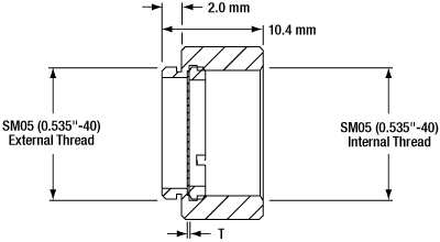
| Housing Diameterc | Ø12.5 mm Polarizers: Ø17.8 mm (Ø0.70") Ø25.0 mm Polarizers: Ø30.5 mm (Ø1.20") | ||||
| Housing Depthc | Ø12.5 mm Polarizers: 10.4 mm (0.41") Ø25.0 mm Polarizers: 11.4 mm (0.45") | ||||
| Clear Aperture | Unmounted | 90% of Surface Dimension | |||
| Mounted | Ø12.5 mm Polarizers: Ø10.9 mm (Ø0.43") Ø25.0 mm Polarizers: Ø22.5 mm (Ø0.88") | ||||
| Wavefront Distortion | Unmounted | < λ/4 @ 633 nm | |||
| Mounted | 3λ @ 633 nm | ||||
| Parallelism | Unmounted | < 1 arcmin | |||
| Mounted | < 20 arcmin | ||||
| Surface Quality | Scratch-Dig: 40-20 (MIL-O-13830A) Surface Imperfections: 5/2 x 0.04 per Ø10 mm (ISO 10110-07) | ||||
| Acceptance Angled | ±20° | ||||
| Laser Damage Threshold | CW | Unmounted: 1 W/cm2; Continuous Block, 5 W/cm2 Continuous Pass Mounted: 10 W/cm2 Continuous Block, 25 W/cm2 Continuous Pass | |||
| Pulsed | - | ||||
| Operating Temperature | Unmounted | -20 to +120 °C | |||
| Mounted | -20 to +120 °C | ||||
| Maintenance | Clean with Standard Cleaning Solvents | ||||
| Item # Prefix | LPNIRB | LPNIRa | LPNIRA | LPNIRC | LPNIRDb | LPNIRFb | LPMIR | |
|---|---|---|---|---|---|---|---|---|
| Wavelength Range | 650 - 1100 nm | 650 - 2000 nm | 1.00 - 3.00 µm | 1.10 - 1.80 µm | 1.26 - 1.36 µm | 1.50 - 1.60 µm | 1.50 - 5.00 µm | |
| AR Coating at 0° AOI | - | - | - | - | Ravg < 0.25% for 1.26 - 1.36 µm | Ravg < 0.25% for 1.50 - 1.60 µm | - | |
| Extinction Ratio Bandsc | ||||||||
| > 100 000 : 1 | - | 850 - 1600 nm | - | - | - | - | - | |
| > 10 000 : 1 | - | 750 - 1800 nm | 1.20 - 3.00 µm | - | 1.26 - 1.36 µm | 1.50 - 1.60 µm | 2.00 - 4.50 µm | |
| > 1000 : 1 | 695 - 1100 nm | 650 - 2000 nm | 1.00 - 3.00 µm | 1.10 - 1.80 µm | - | - | 1.50 - 5.00 µm | |
| > 200:1 | 650 - 695 nm | - | - | - | - | - | - | |
| General Specifications | ||||||||
| Polarizer Material | Nanoparticles in Sodium-Silicate Glass | |||||||
| Substrate Material | Unmounted | None | Schott Glass B270 | None | ||||
| Mounted | None | |||||||
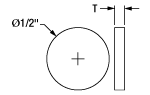
| Optic Diameter | Ø1/2" (Ø12.7 mm) or Ø1" (Ø25.4 mm) | Ø12.5 mm (Ø0.49") or Ø25.0 mm (Ø0.98") | Ø1/2" (Ø12.7 mm) or Ø1" (Ø25.4 mm) | Ø12.5 mm (Ø0.49") or Ø25.0 mm (Ø0.98") | ||||
| Optic Diameter Tolerance | ±0.2 mm (0.008") | |||||||
| Optic Thickness | Unmounted | 550 ± 100 µm | 2.0 ± 0.2 mm | 250 ± 65 µm | 550 ± 100 µm | 90 ± 25 µm | 200 ± 50 µm | |
| Mounted | 220 ± 50 µm | |||||||
| Housing Diameterd | Ø12.5 mm or Ø1/2" Polarizers: Ø17.8 mm (Ø0.70") Ø25.0 mm or Ø1" Polarizers: Ø30.5 mm (Ø1.20") | |||||||
| Housing Depthd | Ø12.5 mm or Ø1/2" Polarizers: 10.4 mm (0.41") Ø25.0 mm or Ø1" Polarizers: 11.4 mm (0.45") | |||||||
| Clear Aperture | Unmounted | 90% of Surface Dimension | ||||||
| Mounted | Ø1/2" Polarizers: Ø10.9 mm (Ø0.43") Ø1" Polarizers: Ø22.9 mm (Ø0.90") | Ø12.5 mm Polarizers: Ø10.9 mm (Ø0.43") Ø25.0 mm Polarizers: Ø22.5 mm (Ø0.88") | Ø1/2" Polarizers: Ø10.9 mm (Ø0.43") Ø1" Polarizers: Ø22.9 mm (Ø0.90") | Ø12.5 mm Polarizers: Ø11.0 mm (Ø0.43") Ø25.0 mm Polarizers: Ø22.5 mm (Ø0.88") | Ø12.5 mm Polarizers: Ø10.9 mm (Ø0.43") Ø25.0 mm Polarizers: Ø22.5 mm (Ø0.88") | |||
| Wavefront Distortion | Unmounted | < λ/4 @ 633 nm | < λ/4 @ 633 nm | < 3λ @ 633 nm | < λ/4 @ 633 nm | < 3λ @ 633 nm | ||
| Mounted | 3λ @ 633 nm | |||||||
| Parallelism | Unmounted | < 0.5 arcmin | < 20 arcmin | < 0.5 arcmin | < 20 arcmin | |||
| Mounted | < 20 arcmin | |||||||
| Surface Quality | Scratch-Dig: 40-20 (MIL-O-13830A) | Scratch-Dig: 40-20 (MIL-O-13830A) Surface Imperfections: 5/2 x 0.04 per Ø10 mm (ISO 10110-07) | N/A | Scratch-Dig: 40-20 (MIL-O-13830A) | Scratch-Dig: 40-20 (MIL-O-13830A) Surface Imperfections: 5/2 x 0.04 per Ø10 mm (ISO 10110-07) | N/A | ||
| Acceptance Anglee | ±20° | |||||||
| Laser Damage Threshold | CW | 10 W/cm2 Continuous Block 25 W/cm2 Continuous Pass | Unmounted: 1 W/cm2 Continuous Block, 5 W/cm2 Continuous Pass Mounted: 10 W/cm2 Continuous Block, 25 W/cm2 Continuous Pass | 10 W/cm2 Continuous Block 25 W/cm2 Continuous Pass | ||||
| Pulsed | 0.006 J/cm2 (800 nm, 100 Hz, 36.4 fs, Ø189 µm) 0.1 J/cm2 (810 nm, 10 Hz, 7.2 ns, Ø0.216 mm) | - | ||||||
| Operating Temperature | Unmounted | -30 to +250 °C | -50 to +400 °C | -30 to +250 °C | -50 to +400 °C | |||
| Mounted | -20 to +120 °C | -20 to +120 °C | -20 to +120 °C | |||||
| Maintenance | Clean with Standard Cleaning Solvents | |||||||
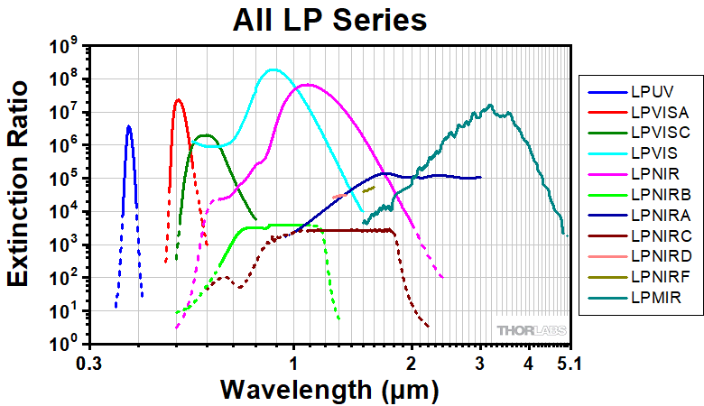
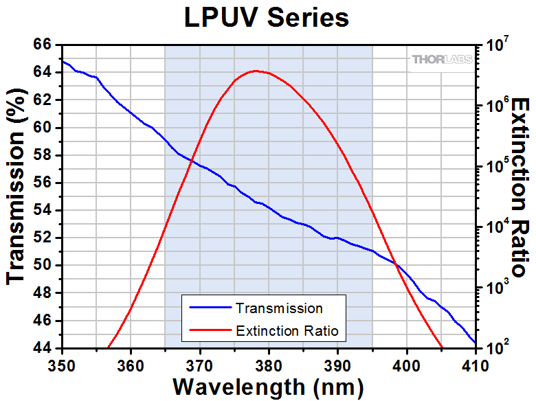
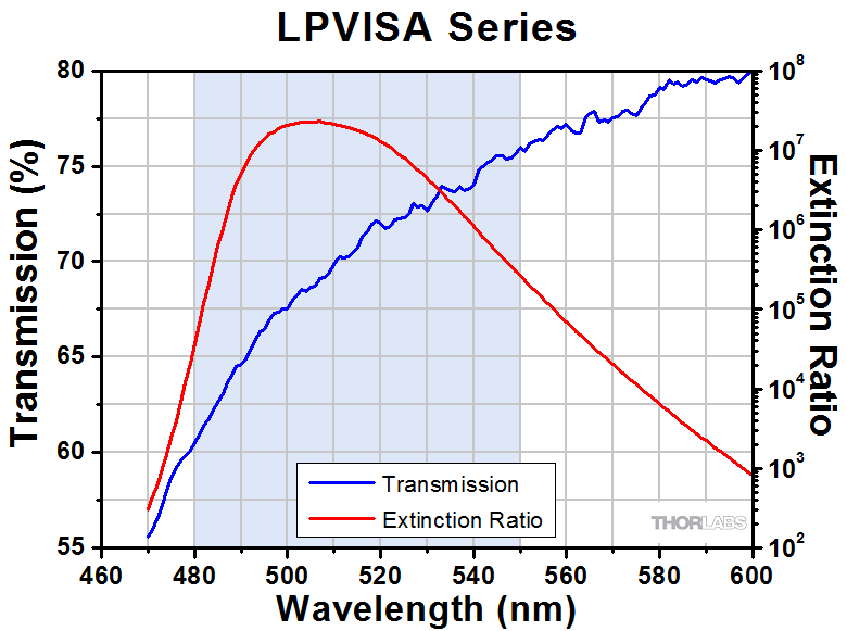
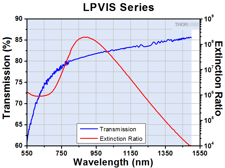
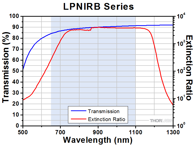
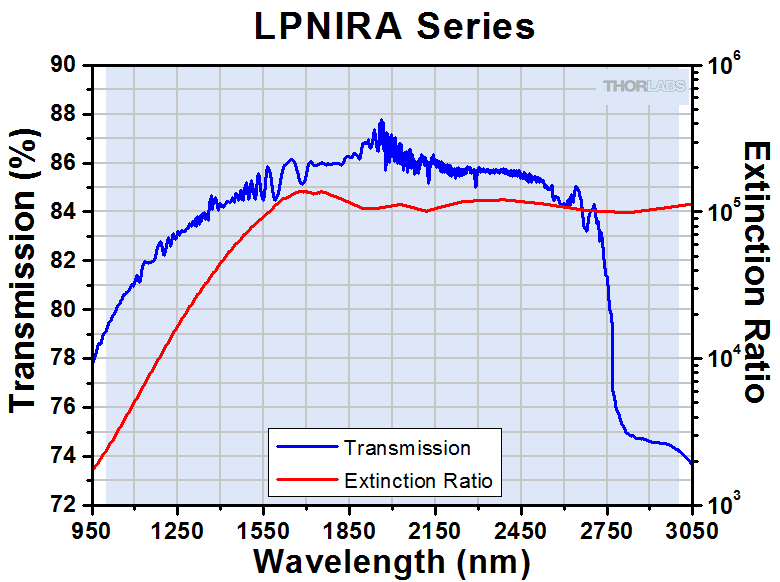
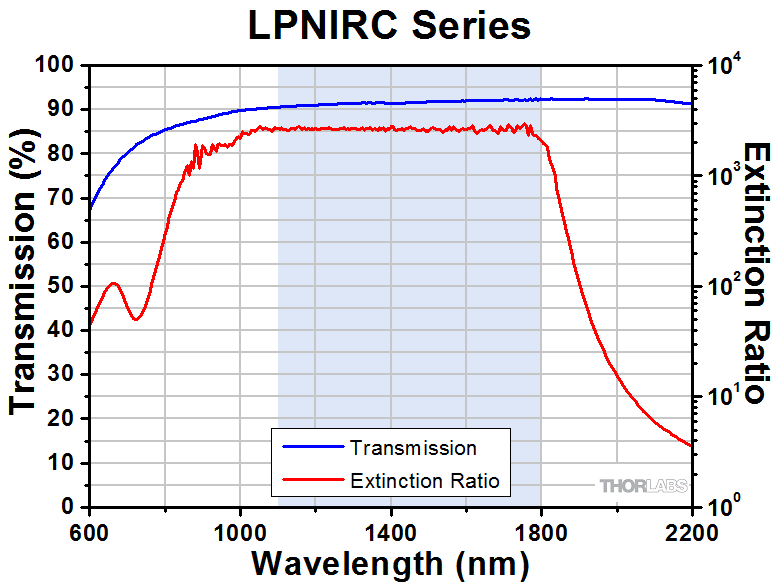
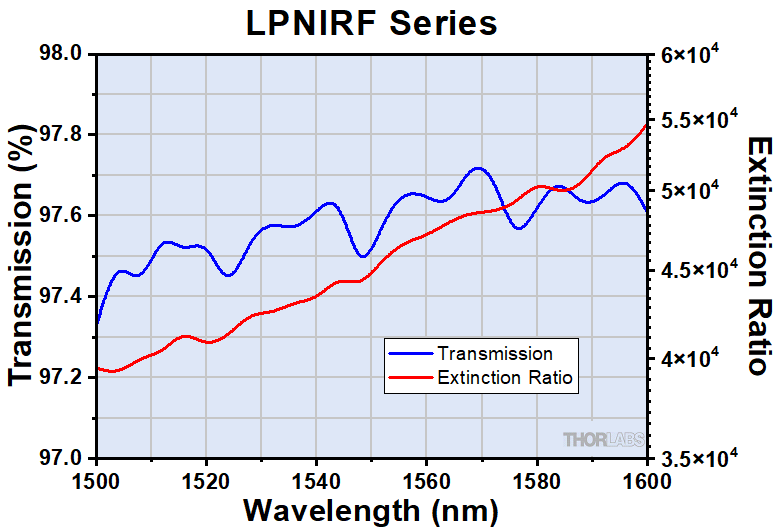
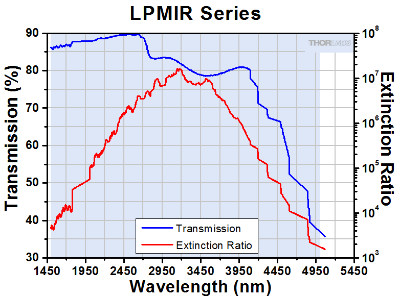
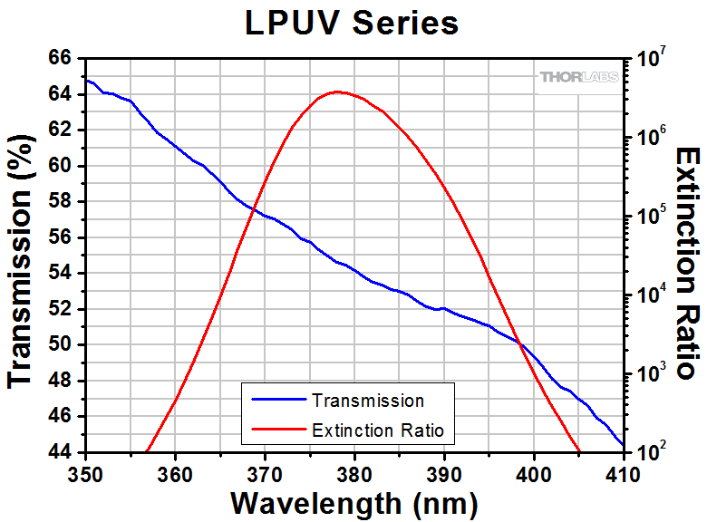
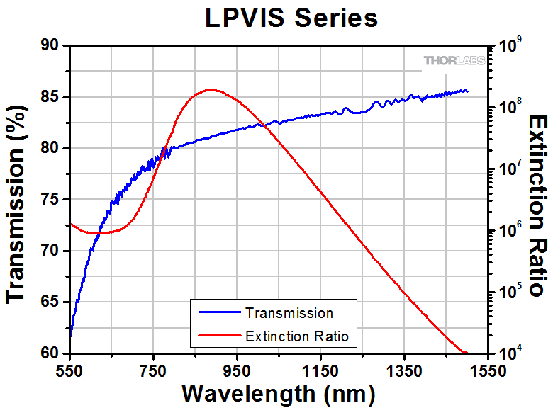
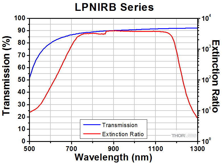
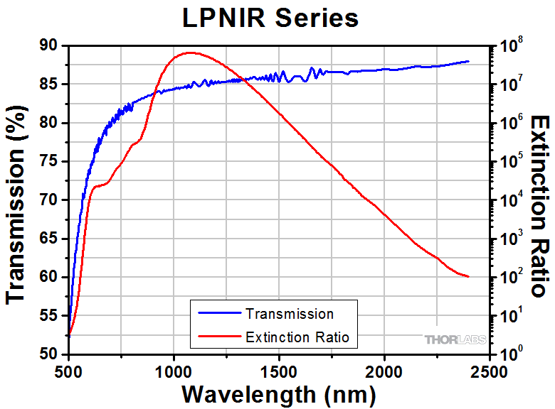
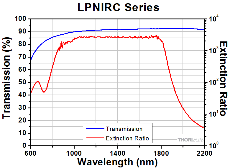
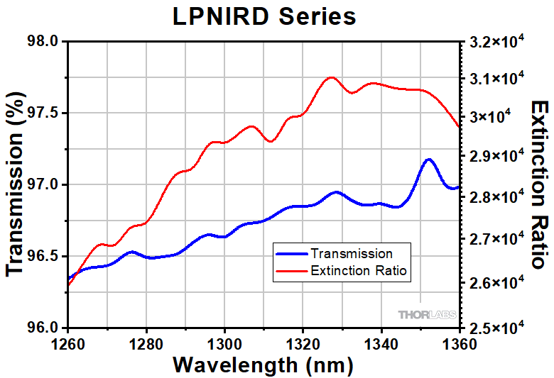
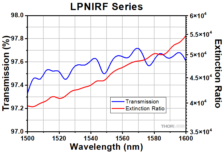
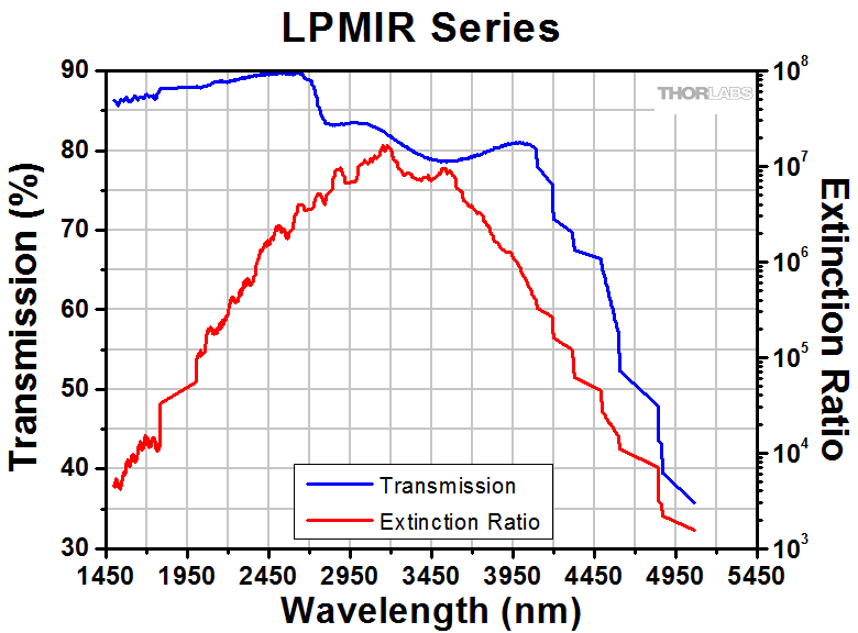
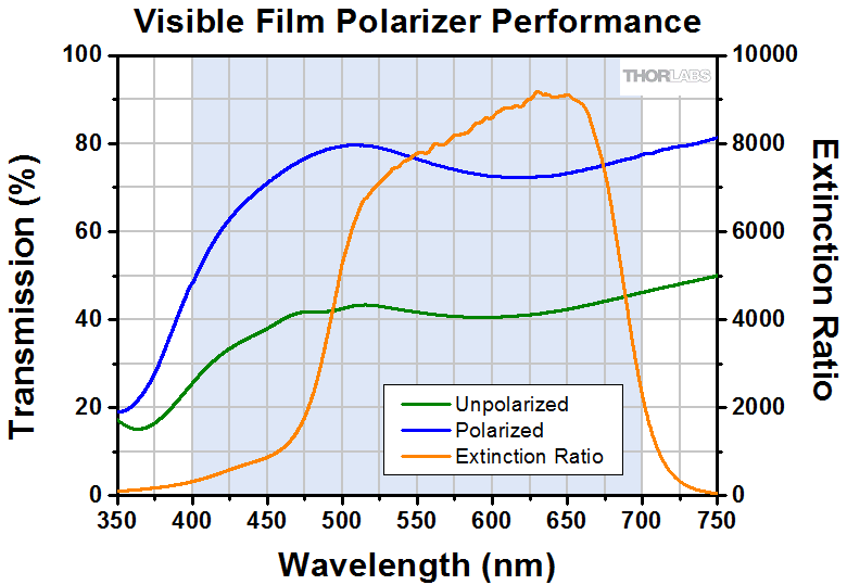
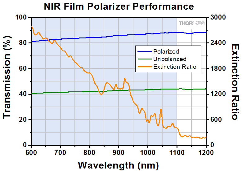
T下のグラフは、光が垂直に入射した場合の各偏光子の透過率の波長特性(測定値)と消光比の波長特性(計算値)を示しています。消光比(ER)の測定値については「仕様」タブをご参照ください。透過率は、直線偏光子の透過偏光軸にアライメントされた直線偏光が入射した時の出力比率を示します。表面反射と内部吸収により、この数字は100%未満になります。ER(消光比)は、偏光子の透過偏光軸に水平な直線偏光が入力したときの光出力強度と、直線偏光子の透過軸に垂直な直線偏光が入力したときの光出力強度の比を示しています。他の偏光子として、1x10⁶のERを有するグランレーザ方解石偏光子や非常に高い損傷閾値を有する方解石偏光子があります。.
Click to Enlarge
T点線は仕様の波長範囲外での直線偏光子の性能を示しています。各偏光子シリーズの詳細にしては下のグラフをご覧ください。
Click to Enlarge
点線は仕様の波長範囲外での直線偏光子の性能を示しています。各偏光子シリーズの詳細については下のグラフをご覧ください。


| Table 5.1 Damage Threshold Specifications | ||
|---|---|---|
| Item # Prefix | Damage Threshold | |
| CW | Pulsed | |
| LPUV | Unmounted Versions: 1 W/cm2 Continuous Block; 5 W/cm2 Continuous Pass Mounted Versions: 10 W/cm2 Continuous Block; 25 W/cm2 Continuous Pass | - |
| LPVISA | ||
| LPVISC | ||
| LPVIS | ||
| LPNIR | ||
| LPNIRB | 10 W/cm2 Continuous Block; 25 W/cm2 Continuous Pass | 0.006 J/cm2 (800 nm, 100 Hz, 36.4 fs, Ø189 µm) 0.1 J/cm2 (810 nm, 7.2 ns, 10 Hz, Ø0.216 mm) |
| LPNIRA | 10 W/cm2 Continuous Block; 25 W/cm2 Continuous Pass | - |
| LPNIRC | ||
| LPNIRD | ||
| LPNIRF | ||
| LPMIR | ||
ナノ粒子フィルム型直線偏光子の損傷閾値データ
Table 5.1はナノ粒子フィルム型直線偏光子の仕様値です。ナノ粒子フィルム型直線偏光子の損傷閾値は、サイズや焦点距離に関わらず全て一定となっております。
レーザによる損傷閾値について
このチュートリアルでは、レーザ損傷閾値がどのように測定され、使用する用途に適切な光学素子の決定にその値をどのようにご利用いただけるかを総括しています。お客様のアプリケーションにおいて、光学素子を選択する際、光学素子のレーザによる損傷閾値(Laser Induced Damage Threshold :LIDT)を知ることが重要です。光学素子のLIDTはお客様が使用するレーザの種類に大きく依存します。連続(CW)レーザは、通常、吸収(コーティングまたは基板における)によって発生する熱によって損傷を引き起こします。一方、パルスレーザは熱的損傷が起こる前に、光学素子の格子構造から電子が引き剥がされることによって損傷を受けます。ここで示すガイドラインは、室温で新品の光学素子を前提としています(つまり、スクラッチ&ディグ仕様内、表面の汚染がないなど)。光学素子の表面に塵などの粒子が付くと、低い閾値で損傷を受ける可能性があります。そのため、光学素子の表面をきれいで埃のない状態に保つことをお勧めします。光学素子のクリーニングについては「光学素子クリーニングチュートリアル」をご参照ください。
テスト方法
当社のLIDTテストは、ISO/DIS 11254およびISO 21254に準拠しています。
初めに、低パワー/エネルギのビームを光学素子に入射します。その光学素子の10ヶ所に1回ずつ、設定した時間(CW)またはパルス数(決められたprf)、レーザを照射します。レーザを照射した後、倍率約100倍の顕微鏡を用いた検査で確認し、すべての確認できる損傷を調べます。特定のパワー/エネルギで損傷のあった場所の数を記録します。次に、そのパワー/エネルギを増やすか減らすかして、光学素子にさらに10ヶ所レーザを照射します。このプロセスを損傷が観測されるまで繰返します。損傷閾値は、光学素子が損傷に耐える、損傷が起こらない最大のパワー/エネルギになります。1つのミラーBB1-E02の試験結果はFigure 37Bのようなヒストグラムになります。
Figure 37A 写真はアルミニウムをコーティングしたミラーでLIDTテストを終えたものです。このテストは、損傷を受ける前のレーザのエネルギは0.43 J/cm2 (1064 nm、10 ns pulse、 10 Hz、Ø1.000 mm)でした。

Figure 37B ミラーBB1-E02のLIDTを決定するために使用した露光のヒストグラム(例)
| Table 37C Example Test Data | |||
|---|---|---|---|
| Fluence | # of Tested Locations | Locations with Damage | Locations Without Damage |
| 1.50 J/cm2 | 10 | 0 | 10 |
| 1.75 J/cm2 | 10 | 0 | 10 |
| 2.00 J/cm2 | 10 | 0 | 10 |
| 2.25 J/cm2 | 10 | 1 | 9 |
| 3.00 J/cm2 | 10 | 1 | 9 |
| 5.00 J/cm2 | 10 | 9 | 1 |
試験結果によれば、ミラーの損傷閾値は 2.00 J/cm2 (532 nm、10 ns pulse、10 Hz、 Ø0.803 mm)でした。尚、汚れや汚染によって光学素子の損傷閾値は大幅に低減されるため、こちらの試験はクリーンな光学素子で行っています。また、特定のロットのコーティングに対してのみ試験を行った結果ではありますが、当社の損傷閾値の仕様は様々な因子を考慮して、実測した値よりも低めに設定されており、全てのコーティングロットに対して適用されています。
CWレーザと長パルスレーザ
光学素子がCWレーザによって損傷を受けるのは、通常バルク材料がレーザのエネルギを吸収することによって引き起こされる溶解、あるいはAR(反射防止)コーティングのダメージによるものです[1]。1 µsを超える長いパルスレーザについてLIDTを論じる時は、CWレーザと同様に扱うことができます。
パルス長が1 nsと1 µs の間のときは、損傷は吸収、もしくは絶縁破壊のどちらかで発生していると考えることができます(CWとパルスのLIDT両方を調べなければなりません)。吸収は光学素子の固有特性によるものか、表面の不均一性によるものかのどちらかによって起こります。従って、LIDTは製造元の仕様以上の表面の質を有する光学素子にのみ有効です。多くの光学素子は、ハイパワーCWレーザで扱うことができる一方、アクロマティック複レンズのような接合レンズやNDフィルタのような高吸収光学素子は低いCWレーザ損傷閾値になる傾向にあります。このような低い損傷閾値は接着剤や金属コーティングにおける吸収や散乱によるものです。
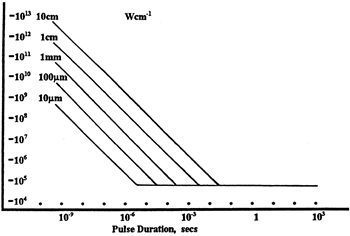
Figure 37D 線形パワー密度におけるLIDTに対するパルス長とスポットサイズ。長パルス~CWでは線形パワー密度はスポットサイズにかかわらず一定です。 このグラフの出典は[1]です。
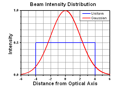
Figure 37E 均一ビームとガウシアンビームの強度分布プロファイル
繰返し周波数(prf)の高いパルスレーザは、光学素子に熱的損傷も引き起こします。この場合は吸収や熱拡散率のような因子が深く関係しており、残念ながらprfの高いレーザが熱的影響によって光学素子に損傷を引き起こす場合の信頼性のあるLIDTを求める方法は確立されておりません。prfの大きいビームでは、平均出力およびピークパワーの両方を等しいCW出力と比較する必要があります。また、非常に透過率の高い材料では、prfが上昇してもLIDTの減少は皆無かそれに近くなります。
ある光学素子の固有のCWレーザの損傷閾値を使う場合には、以下のことを知る必要があります。
- レーザの波長
- ビーム径(1/e2)
- ビームのおおよその強度プロファイル(ガウシアン型など)
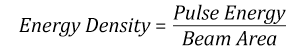
- レーザのパワー密度(トータルパワーをビームの強度が1/e2の範囲の面積で割ったもの)
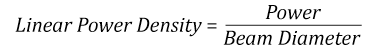
ビームのパワー密度はW/cmの単位で計算します。この条件下では、出力密度はスポットサイズとは無関係になります。つまり、スポットサイズの変化に合わせてLIDTを計算し直す必要がありません(Figure 37D参照)。平均線形パワー密度は、下の計算式で算出できます。
ここでは、ビーム強度プロファイルは一定であると仮定しています。次に、ビームがホットスポット、または他の不均一な強度プロファイルの場合を考慮して、おおよその最大パワー密度を計算する必要があります。ご参考までに、ガウシアンビームのときはビームの強度が1/e2の2倍のパワー密度を有します(Figure 37E参照)。
次に、光学素子のLIDTの仕様の最大パワー密度を比較しましょう。損傷閾値の測定波長が光学素子に使用する波長と異なっている場合には、その損傷閾値は適宜補正が必要です。おおよその目安として参考にできるのは、損傷閾値は波長に対して比例関係であるということです。短い波長で使う場合、損傷閾値は低下します(つまり、1310 nmで10 W/cmのLIDTならば、655 nmでは5 W/cmと見積もります)。
この目安は一般的な傾向ですが、LIDTと波長の関係を定量的に示すものではありません。例えば、CW用途では、損傷はコーティングや基板の吸収によってより大きく変化し、必ずしも一般的な傾向通りとはなりません。上記の傾向はLIDT値の目安として参考にしていただけますが、LIDTの仕様波長と異なる場合には当社までお問い合わせください。パワー密度が光学素子の補正済みLIDTよりも小さい場合、この光学素子は目的の用途にご使用いただけます。
当社のウェブ上の損傷閾値の仕様と我々が行った実際の実験の値の間にはある程度の差があります。これはロット間の違いによって発生する誤差を許容するためです。ご要求に応じて、当社は個別の情報やテスト結果の証明書を発行することもできます。損傷解析は、類似した光学素子を用いて行います(お客様の光学素子には損傷は与えません)。試験の費用や所要時間などの詳細は、当社までお問い合わせください。
パルスレーザ
先に述べたように、通常、パルスレーザはCWレーザとは異なるタイプの損傷を光学素子に引き起こします。パルスレーザは損傷を与えるほど光学素子を加熱しませんが、光学素子から電子をひきはがします。残念ながら、お客様のレーザに対して光学素子のLIDTの仕様を照らし合わせることは非常に困難です。パルスレーザのパルス幅に起因する光学素子の損傷には、複数の形態があります。Table 37Fのハイライトされた列は当社の仕様のLIDT値が当てはまるパルス幅に対する概要です。
パルス幅が10-9 sより短いパルスについては、当社の仕様のLIDT値と比較することは困難です。この超短パルスでは、多光子アバランシェ電離などのさまざまなメカニクスが損傷機構の主流になります[2]。対照的に、パルス幅が10-7 sと10-4 sの間のパルスは絶縁破壊、または熱的影響により光学素子の損傷を引き起こすと考えられます。これは、光学素子がお客様の用途に適しているかどうかを決定するために、レーザービームに対してCWとパルス両方による損傷閾値を参照しなくてはならないということです。
| Table 37F Laser Induced Damage Regimes | ||||
|---|---|---|---|---|
| Pulse Duration | t < 10-9 s | 10-9 < t < 10-7 s | 10-7 < t < 10-4 s | t > 10-4 s |
| Damage Mechanism | Avalanche Ionization | Dielectric Breakdown | Dielectric Breakdown or Thermal | Thermal |
| Relevant Damage Specification | No Comparison (See Above) | Pulsed | Pulsed and CW | CW |
お客様のパルスレーザに対してLIDTを比較する際は、以下のことを確認いただくことが重要です。
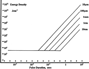
Figure 37G エネルギ密度におけるLIDTに対するパルス長&スポットサイズ。短パルスでは、エネルギ密度はスポットサイズにかかわらず一定です。このグラフの出典は[1]です。
- レーザの波長
- ビームのエネルギ密度(トータルエネルギをビームの強度が1/e2の範囲の面積で割ったもの)
- レーザのパルス幅
- パルスの繰返周波数(prf)
- 実際に使用するビーム径(1/e2 )
- ビームのおおよその強度プロファイル(ガウシアン型など)
ビームのエネルギ密度はJ/cm2の単位で計算します。Figure 37Gは、短パルス光源には、エネルギ密度が適した測定量であることを示しています。この条件下では、エネルギ密度はスポットサイズとは無関係になります。つまり、スポットサイズの変化に合わせてLIDTを計算し直す必要がありません。ここでは、ビーム強度プロファイルは一定であると仮定しています。ここで、ビームがホットスポット、または他の不均一な強度プロファイルの場合を考慮して、おおよその最大パワー密度を計算する必要があります。ご参考までに、ガウシアンビームのときは一般にビームの強度が1/e2のときの2倍のパワー密度を有します。
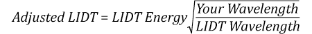
次に、光学素子のLIDTの仕様と最大エネルギ密度を比較しましょう。損傷閾値の測定波長が光学素子に使用する波長と異なっている場合には、その損傷閾値は適宜補正が必要です[3]。経験則から、損傷閾値は波長に対して以下のような平方根の関係であるということです。短い波長で使う場合、損傷閾値は低下します(例えば、1064 nmで 1 J/cm2のLIDTならば、532 nmでは0.7 J/cm2と計算されます)。
波長を補正したエネルギ密度を得ました。これを以下のステップで使用します。
ビーム径は損傷閾値を比較する時にも重要です。LIDTがJ/cm2の単位で表される場合、スポットサイズとは無関係になりますが、ビームサイズが大きい場合、LIDTの不一致を引き起こす原因でもある不具合が、より明らかになる傾向があります[4]。ここで示されているデータでは、LIDTの測定には<1 mmのビーム径が用いられています。ビーム径が5 mmよりも大きい場合、前述のようにビームのサイズが大きいほど不具合の影響が大きくなるため、LIDT (J/cm2)はビーム径とは無関係にはなりません。
次に、パルス幅について補正します。パルス幅が長くなるほど、より大きなエネルギに光学素子は耐えることができます。パルス幅が1~100 nsの場合の近似式は以下のようになります。
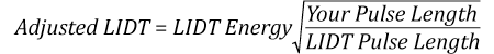
お客様のレーザのパルス幅をもとに、光学素子の補正されたLIDTを計算するのにこの計算式を使います。お客様の最大エネルギ密度が、この補正したエネルギ密度よりも小さい場合、その光学素子はお客様の用途でご使用いただけます。ご注意いただきたい点は、10-9 s と10-7 sの間のパルスにのみこの計算が使えることです。パルス幅が10-7 sと10-4 sの間の場合には、CWのLIDTも調べなければなりません。
当社のウェブ上の損傷閾値の仕様と我々が行った実際の実験の値の間にはある程度の差があります。これはロット間の違いによって発生する誤差を許容するためです。ご要求に応じて、当社では個別のテスト情報やテスト結果の証明書を発行することも可能です。詳細は、当社までお問い合わせください。
[1] R. M. Wood, Optics and Laser Tech. 29, 517 (1998).
[2] Roger M. Wood, Laser-Induced Damage of Optical Materials (Institute of Physics Publishing, Philadelphia, PA, 2003).
[3] C. W. Carr et al., Phys. Rev. Lett. 91, 127402 (2003).
[4] N. Bloembergen, Appl. Opt. 12, 661 (1973).

レーザーシステムが光学素子に損傷を引き起こすかどうか判断するプロセスを説明するために、レーザによって引き起こされる損傷閾値(LIDT)の計算例をいくつかご紹介します。同様の計算を実行したい場合には、右のボタンをクリックしてください。計算ができるスプレッドシートをダウンロードいただけます。ご使用の際には光学素子のLIDTの値と、レーザーシステムの関連パラメータを緑の枠内に入力してください。スプレッドシートでCWならびにパルスの線形パワー密度、ならびにパルスのエネルギ密度を計算できます。これらの値はスケーリング則に基づいて、光学素子のLIDTの調整スケール値を計算するのに用いられます。計算式はガウシアンビームのプロファイルを想定しているため、ほかのビーム形状(均一ビームなど)には補正係数を導入する必要があります。 LIDTのスケーリング則は経験則に基づいていますので、確度は保証されません。なお、光学素子やコーティングに吸収があると、スペクトル領域によってLIDTが著しく低くなる場合があります。LIDTはパルス幅が1ナノ秒(ns)未満の超短パルスには有効ではありません。
Figure 71A ガウシアンビームの最大強度は均一ビームの約2倍です。
CWレーザの例
波長1319 nm、ビーム径(1/e2)10 mm、パワー0.5 Wのガウシアンビームを生成するCWレーザーシステム想定します。このビームの平均線形パワー密度は、全パワーをビーム径で単純に割ると0.5 W/cmとなります。
しかし、ガウシアンビームの最大パワー密度は均一ビームの約2倍です(Figure 71A参照)。従って、システムのより正確な最大線形パワー密度は1 W/cmとなります。
アクロマティック複レンズAC127-030-CのCW LIDTは、1550 nmでテストされて350 W/cmとされています。CWの損傷閾値は通常レーザ光源の波長に直接スケーリングするため、LIDTの調整値は以下のように求められます。
LIDTの調整値は350 W/cm x (1319 nm / 1550 nm) = 298 W/cmと得られ、計算したレーザーシステムのパワー密度よりも大幅に高いため、この複レンズをこの用途に使用しても安全です。
ナノ秒パルスレーザの例:パルス幅が異なる場合のスケーリング
出力が繰返し周波数10 Hz、波長355 nm、エネルギ1 J、パルス幅2 ns、ビーム径(1/e2)1.9 cmのガウシアンビームであるNd:YAGパルスレーザーシステムを想定します。各パルスの平均エネルギ密度は、パルスエネルギをビームの断面積で割って求めます。
上で説明したように、ガウシアンビームの最大エネルギ密度は平均エネルギ密度の約2倍です。よって、このビームの最大エネルギ密度は約0.7 J/cm2です。
このビームのエネルギ密度を、広帯域誘電体ミラーBB1-E01のLIDT 1 J/cm2、そしてNd:YAGレーザーラインミラーNB1-K08のLIDT 3.5 J/cm2と比較します。LIDTの値は両方とも、波長355 nm、パルス幅10 ns、繰返し周波数10 Hzのレーザで計測しました。従って、より短いパルス幅に対する調整を行う必要があります。 1つ前のタブで説明したようにナノ秒パルスシステムのLIDTは、パルス幅の平方根にスケーリングします:
この調整係数により広帯域誘電体ミラーBB1-E01のLIDTは0.45 J/cm2に、Nd:YAGレーザーラインミラーのLIDTは1.6 J/cm2になり、これらをビームの最大エネルギ密度0.7 J/cm2と比較します。広帯域ミラーはレーザによって損傷を受ける可能性があり、より特化されたレーザーラインミラーがこのシステムには適していることが分かります。
ナノ秒パルスレーザの例:波長が異なる場合のスケーリング
波長1064 nm、繰返し周波数2.5 Hz、パルスエネルギ100 mJ、パルス幅10 ns、ビーム径(1/e2)16 mmのレーザ光を、NDフィルタで減衰させるようなパルスレーザーシステムを想定します。これらの数値からガウシアン出力における最大エネルギ密度は0.1 J/cm2になります。Ø25 mm、OD 1.0の反射型NDフィルタ NDUV10Aの損傷閾値は355 nm、10 nsのパルスにおいて0.05 J/cm2で、同様の吸収型フィルタ NE10Aの損傷閾値は532 nm、10 nsのパルスにおいて10 J/cm2です。1つ前のタブで説明したように光学素子のLIDTは、ナノ秒パルス領域では波長の平方根にスケーリングします。
スケーリングによりLIDTの調整値は反射型フィルタでは0.08 J/cm2、吸収型フィルタでは14 J/cm2となります。このケースでは吸収型フィルタが光学損傷を防ぐには適した選択肢となります。
マイクロ秒パルスレーザの例
パルス幅1 µs、パルスエネルギ150 µJ、繰返し周波数50 kHzで、結果的にデューティーサイクルが5%になるレーザーシステムについて考えてみます。このシステムはCWとパルスレーザの間の領域にあり、どちらのメカニズムでも光学素子に損傷を招く可能性があります。レーザーシステムの安全な動作のためにはCWとパルス両方のLIDTをレーザーシステムの特性と比較する必要があります。
この比較的長いパルス幅のレーザが、波長980 nm、ビーム径(1/e2)12.7 mmのガウシアンビームであった場合、線形パワー密度は5.9 W/cm、1パルスのエネルギ密度は1.2 x 10-4 J/cm2となります。これをポリマーゼロオーダ1/4波長板WPQ10E-980のLIDTと比較してみます。CW放射に対するLIDTは810 nmで5 W/cm、10 nsパルスのLIDTは810 nmで5 J/cm2です。前述同様、光学素子のCW LIDTはレーザ波長と線形にスケーリングするので、CWの調整値は980 nmで6 W/cmとなります。一方でパルスのLIDTはレーザ波長の平方根とパルス幅の平方根にスケーリングしますので、1 µsパルスの980 nmでの調整値は55 J/cm2です。光学素子のパルスのLIDTはパルスレーザのエネルギ密度よりはるかに大きいので、個々のパルスが波長板を損傷することはありません。しかしレーザの平均線形パワー密度が大きいため、高出力CWビームのように光学素子に熱的損傷を引き起こす可能性があります。
| Posted Comments: | |
Mohammad Rezaei Pandari
(posted 2025-11-28 17:38:46.03) We are planning to incorporate a polarizer into our beamline setup.
We require an assessment of its suitability based on the following high-intensity ultra-fast pulse parameters:
Pulse Duration : 5 fs,
Spectral Range : 580–1040 nm
Pulse Energy : 150 mJ
Beam Diameter : 5 cm
Our primary concern is the damage threshold of a typical high-power optic under these conditions. Given the short pulse duration (5 fs) and high energy (150 mJ), can you advise on the feasibility of using a standard commercially available polarizer, and what type you would recommend? If a standard optic is unsuitable, please suggest specific alternative designs that meet our operational requirements.
Thank you for your assistance.
Best regards, sacosta
(posted 2025-12-01 08:17:42.0) Thanks for reaching out. I have contacted you via email to discuss your application and help you find a suitable polarizer for it. Chenxing Li
(posted 2025-08-18 04:16:47.303) May I request if I can obtain more information about this polarizing filter regarding its transmittance and extinction ratio? The range should preferably be from 390nm to 1500nm. hkarpenko
(posted 2025-08-18 08:19:05.0) Dear Chenxing,
thank you for your feedback. The transmission of the requested polarizer LPVIS100-MP2 will vary between 10% and 50% for wavelengths between 390nm and 500nm, whereas the extinction ratio will drop significantly. I will contact you directly to discuss this further in detail with you. Jiarui Xing
(posted 2025-07-24 20:57:56.18) I want to know how to choose the polarizer during the femtosecond laser experiment. What's the damage threshold? Or maybe I can get specific polarizers for the ultrafast experiments? sacosta
(posted 2025-07-25 06:46:09.0) Thanks for reaching out. I have contacted you via email to help you find a suitable polarizer for use with your laser. Ilkyu Park
(posted 2025-01-08 12:13:31.86) I have a question regarding the use of the LPVIS100 product. For certain polarization cases, is it possible for the light exiting the LPVIS100 to undergo a parallel shift even when incident vertically? tschmidt
(posted 2025-01-08 10:19:32.0) Dear Ilkyu, thank you for your feedback. I have contacted you directly to discuss further details with you. user
(posted 2024-05-22 16:36:54.47) Hello,
I would like to inquire about the LPVIS product. When used for long periods (below the damage threshold), does the transmission change due to the thermal effects from light absorption by the polarizer? Or does the transmission remain constant over time?
Thank you. dpossin
(posted 2024-05-24 04:53:26.0) Dear customer,
Since the transmission, the LPVIS provides is rather high, there is no thermal effect on the transmission expected as long as the damage threshold are maintained. Kilian Muller
(posted 2024-02-29 11:01:27.1) Bonjour,
I was looking for the transmission data for your LPNIRB100 polarizer - like you provide for your economy film polarizers - but could not find it.
Specifically, I am interested in the transmission and extinction ratio at 780 nm.
I would be very happy if you could send me that data.
Furthermore I would like to know whether it was possible for you to sell this polarizer in a rectangular shape (let's say 20 mm x 30 mm), with the polarization axis aligned with one of the axes of the rectangle.
Best regards,
Kilian Muller cdolbashian
(posted 2024-03-18 04:34:58.0) Thank you for contacting Thorlabs. The raw data for transmission and ER can be downloaded by clicking the hyperlink under the "Graphs" tab. (Please note that the data shown here is typical; slight variations in performance data may occur from lot to lot.) The typical transmission and ER of the LPNIRB series for 780nm are 88.6432% and 3180.70979, respectively. We can provide a custom rectangular shape upon request. We will contact you directly to discuss the possibility of offering this customization. Alternatively, feel free to reach out to your local Tech Support group ( techsupport.fr@thorlabs.com in your case) in the future when inquiring about custom versions of stock items in our web catalog user
(posted 2024-01-15 21:32:57.527) Is there an inherent physical reason, why the Operating
Temperature range is limited down to -20°C (like shifts in the nanoparticles absorption)? Or could the polarizer in principle also be used at cryogenic temperatures (-210°C)(damage caused by breakage due to stresses in the glass etc. neglected)? hkarpenko
(posted 2024-01-18 04:02:52.0) Dear Stefan,
thank you very much for your feedback. The specified temperature range is limited due to the properties of the material and this is the safe range to use it. However I will contact you directly to discuss further possibilities with you. APR TriLite
(posted 2023-12-18 13:33:44.91) Hi, I see a beam displacement in case of mounted as well as unmounted polarizers. This manifests as the beam rotating about the axis of the polarizer when the polarizer is rotated. I have noticed it in LPVIS050-MP2 and in LPVISE100-A. I have tried to mount the polarizer as normal to the beam as possible,but this still exists. Could you please explain why this happens ? Also, is this angular beam displacement given by the property parallelism in the Specs tab. For all mounted polarizers this is indicated to be 20 arc minutes. Am I understanding it correct that this will amount to a beam displacement of 0.58mm per 100 mm of beam propagation ? hchow
(posted 2023-12-19 05:39:42.0) Dear Sir/Madam, thank you for your enquiry. The beam displacement you are observing is indeed due to the unfortunate consequence of the 20 arcmin parallelism of the polariser. 0,58 mm shift per 100 mm beam propagation is also correct. If you wish to minimise the beam displacement, I can suggest that you purchase our unmounted polarisers instead, as the parallelism is specced at just 1 arcmin only. Garland Best
(posted 2023-07-26 07:40:41.113) We are wittnessing an issue with the polarizers we ordered. There is a background pattern of light being scattered around the central beam we are blocking. This scattered light is being detected by our measurements, limiting our ability to measure the polarization state of the light. being transmitted. I can provide images to show this.
Please contact us ASAP so we can resolve this. Thank you. hkarpenko
(posted 2023-07-28 04:24:32.0) Dear Garland,
thank you for your feedback. This issue can have several reasons. For instance the AOI or wavelength of you beam. I will contact you directly to discuss this in detail with you. user
(posted 2023-06-02 14:51:31.727) Hello, what are the optical consequences of having a polarizer before or after the imaging lens?
Thank you hchow
(posted 2023-06-05 11:02:05.0) Thank you for contacting us!
Differences in putting a polarizer before or after the lens can be manifold. For instance, in general, putting a flat substrate after the lens will create aberrations that may increase the spot size and focal length of the lens more than putting it before the lens.
On the other hand, putting a polarizer after the lens may help reduce glare effect originating in the lens itself in case it consists of multiple optical elements. Presence of a glare effect may be also related on the quality of the lens.
We will contact you directly to discuss further details of your setup. hchow
(posted 2023-06-05 11:02:05.0) Thank you for contacting us!
Differences in putting a polarizer before or after the lens can be manifold. For instance, in general, putting a flat substrate after the lens will create aberrations that may increase the spot size and focal length of the lens more than putting it before the lens.
On the other hand, putting a polarizer after the lens may help reduce glare effect originating in the lens itself in case it consists of multiple optical elements. Presence of a glare effect may be also related on the quality of the lens.
We will contact you directly to discuss further details of your setup. Yutong Feng
(posted 2023-03-30 09:37:34.87) Hello,
To use the LPNIR100-MP2 properly, should the incident
collimated beam be in the center of the polarizer? What would be changed, eg transmission, if the beam not hitting the center but close to the edge?
Many thanks. hchow
(posted 2023-04-03 07:56:33.0) Dear Ms. Feng, thank you for your feedback. So long as the collimated laser beam is incident on the surface and well within the diameter of the polariser, there should not be any degradation in the transmission ratio of the output beam. John McPhillimy
(posted 2022-11-03 04:01:51.457) Hello,
I was hoping for some information on the polarization filter extinction relative to angular incidence of input source beam.
If the input beam is deflected prior to the polariser such that we have a 5-40degree angle away from the normal, how does this impact the polarisation control via the polarizer?
This is if we are working in both a linear and circular state prior to the final polariser.
Thank you, John hkarpenko
(posted 2022-11-08 08:04:07.0) Dear John,
thank you for your feedback.
The incident angle has an impact on the ER. However, for these polarisers we specify an acceptance angle of ±20°. That means, in that region the ER won´t change much and will be in the range of the specifications we state, but best performance is achieved using 0° AOI.
I contact you directly to discuss this topic further with you. user
(posted 2022-07-15 13:15:43.007) ... and I would like to ask the same thing, regarding the preferred direction of propagation of light, for LPVISA100-MP2, 480 - 550 nm. Thank you mdiekmann
(posted 2022-07-18 11:32:57.0) Thank you for contacting us! These can be used in both directions. We will contact you directly to troubleshoot this issue. user
(posted 2022-07-15 12:31:16.83) Hi, I would like to ask which is the preferred direction of propagation of light, for LPNIR100-MP2 - Ø25.0 mm SM1, 650-2000 nm. I ask because there is no arrow on the ring, and I see a difference depending on the orientation. Thanks you very much aprokofiew
(posted 2025-11-05 03:49:19.0) Thank you for contacting Thorlabs. For the LPNIR100-MP2 nanoparticle linear film polarizer, there is no preferred direction of propagation. Observed differences in your setup can result from beam alignment, angle of incidence, or reflections from nearby surfaces, rather than the orientation of the polarizer itself. Antoni Kocot
(posted 2022-04-05 11:22:10.803) Quote
LPVISB100 - Ø25.0 mm Unmounted Linear Polarizer, 500 - 720 nm jgreschler
(posted 2022-04-06 03:17:52.0) Thank you for reaching out to Thorlabs. LPVISB100 was obsoleted in June 2017, the replacement product is LPVISC100. The two units have the same size, the focal range is slightly shifted for the new unit (510-800nm versus 500-720 for the old unit). I have reached out to you directly to confirm replacement and set up a quote. user
(posted 2021-06-08 15:48:50.887) Hi, I am wondering why you didn't specify the extinction ratio of > 100 000:1 for LPVISA in the table of extinction ratio bands? I would like to know which one (LPVISA and LPVISC) is better for 532-nm laser. Thanks. MKiess
(posted 2021-06-11 09:14:59.0) This is a response from Michael at Thorlabs. Thank you very much for your inquiry. The LPVISA has the better extinction ratio at 532nm. You can see the comparison very well in the Extinction Ratio Graph, which you can find in the Linear Polarizer Selection Guide table, in the Overview Tab.
I have contacted you directly for further support. Vladimir Makarov
(posted 2020-06-04 10:20:40.07) Hello,
The Solidworks 3D CAD model for this part is in German. Could you please fix this and make it in English. We are using this model in our equipment assembly 3D CAD, and the German is confusing. MKiess
(posted 2020-06-10 06:20:03.0) This is a response from Michael at Thorlabs. Thank you very much for your feedback. That's correct. We will adjust that immediately. Thank you very much for this information. Angel Fernandez
(posted 2020-01-31 04:05:34.34) Hi,
What is the refraction index of the LPVISC100-MP2 polarizer at 633nm wavelength? Thank you in advance. MKiess
(posted 2020-02-03 11:27:53.0) This is a response from Michael at Thorlabs. Thank you very much for your inquiry. The refraction index of the LPVISC100-MP2 polarizer at 633nm is ~1.52. I have sent you contacted you directly to provide further details. Seungeun Oh
(posted 2019-08-21 02:59:19.98) Has anyone tried if these polarizers work for 2W, 700 - 1064 nm NIR pulse lasers of ~200 fsec pulse duration, 80 MHz repetition rate? The average irradiance is 0.4 W/mm2, and estimated peak irradiance is 40 kW/mm2. MKiess
(posted 2019-08-22 11:47:41.0) This is a response from Michael at Thorlabs. Thank you very much for your inquiry. We once tested an LPNIRA100-MP2 with a 150fs pulsed laser at a wavelength of 2200nm with an average power density of 0.16W/mm^2. The repetition rate was 82Hz. The filter did not withstand this laser. Therefore the filter will not withstand a laser with the specifications described by you. Petter Westbergh
(posted 2019-05-16 11:00:45.26) How does the polarizer's transmission axis align with the marks on the side of the polarizer? YLohia
(posted 2019-05-16 02:52:43.0) The polarizer's transmission axis is indicated by two black marks on the edge of every unmounted polarizer except the LPNIRA050, LPMIR050, LPNIRA100, and LPMIR100. On the mounted polarizers, the polarization axis is indicated by engraved white lines on the housing. adarshjain
(posted 2018-08-29 03:22:18.73) Hi,
We want to procure LPNIR100-MP2 polarizer.
Our pulsed laser o/p requirements is as follows;
(a) Pavg: 100mW
(b) repetition rate: 10 MHz
(c) Pulse duration: 10ns
As laser damage threshold is written as 25W/cm2, can we use it for our application?
Please reply on urgent basis. nreusch
(posted 2018-09-06 04:53:34.0) This is a response from Nicola at Thorlabs. Thank you for your inquiry. In order to determine the intensity of your laser beam, I need to know the beam diameter. Would you like to use it in pass orientation only? I will contact you directly to discuss this in more detail. ivan.sytcevich
(posted 2018-05-07 10:48:34.937) Hello,
I was wondering if you make custom sized thin film polarizers. I need two rectangular polarizers with dimensions of 8 x3.5 mm (visible - NIR range) in order to use them with the SLM for amplitude modulation. swick
(posted 2018-05-15 03:49:11.0) This is a response from Sebastian at Thorlabs. Thank you for the inquiry.
We can offer the Nanoparticle Film Polarizer with customized dimensions. I contacted you directly. ahackler
(posted 2017-06-28 10:32:28.59) I am slightly confused by how you explain the CW damage threshold as some of the terms aren't defined. My question is: I have a 488nm CW laser operating at 20mW with a beam diameter of 0.7 mm, would the film polarizers survive? wskopalik
(posted 2017-06-29 04:28:54.0) This is a response from Wolfgang at Thorlabs. Thank you very much for your inquiry.
There are two damage threshold values specified for these polarizers. This is because the damage threshold depends on how the polarisation of the incoming light is oriented with regards to the polarizer. If the light is oriented so it is blocked by the polarizer, the light will be absorbed in the polarizer. This generates heat and can damage the polarizer if the power of the light is too high. In pass direction much less absorption takes place, therefore the applied power can be higher.
In your case the power density is about 5.2 W/cm2. This is too much for the LPVISA050 even in pass direction. So the polarizer would be damaged. An alternative would be the mounted version LPVISA050-MP2 which has the same extinction ratio but can handle higher powers. This is because the mounted version doesn't have lamination layers.
I will contact you directly to provide further assistance. kko
(posted 2017-06-07 09:48:56.33) Hello,
I want to use the LPVIS100.
Is there any evaluation about the homogeneity of the ER over the surface ?
The guarantied ER at specific wavelength is several orders below the theoretical calculated. Is there a knowledge about the variance to be expected ?
greetings
martin swick
(posted 2017-06-14 03:26:10.0) This is a response from Sebastian at Thorlabs. Thank you for the inquiry.
The fluctuation of the ER at the Nanoparticle Linear Film Polarizer over the clear aperture is very small. I have contacted you directly to provide assistance. zhiheng
(posted 2015-10-27 23:43:34.93) Hi there, I have a couple of LPVISB050-MP2 polarizers in my lab. Over the course of a couple of months, the polarizers develop a discoloration that is accompanied by a dramatic decrease in the extinction ratio (<10:1), making them unusable. This is even though the polarizers are used mostly with their polarization axes aligned with that of the incident laser beam. The incident laser beam has the following parameters: ~6 mW average power, 1 kHz pulse repetition rate, <10 fs pulse duration, 5 mm beam diameter (1/e^2), 550 - 720 nm wavelength. What could be causing the polarizers to be damaged? I would like to use these polarizers as much as possible because their thin substrates make them compatible with ultrashort pulses. Any advice that you can provide would be greatly appreciated. Thank you! besembeson
(posted 2015-10-28 05:39:46.0) Response from Bweh at Thorlabs USA: Though your average power is low, with such ultra-short pulses, the dominant damage mechanism is avalanche ionization. It is not clear however if the discoloration is random on the surface or only around areas used with the beam. I will contact you to clarify this further. elijah.dale
(posted 2015-03-06 13:19:03.85) What is the index of refraction of the polarizer (LPNIR050) at a wavelength of 1.55 um? shallwig
(posted 2015-03-09 10:29:48.0) This is a response from Stefan at Thorlabs. Thank you very much for your inquiry. The LPNIR050 has the same optical properties as B270 glass but unfortunately we do not have specific data for the refractive index at 1550nm. I will contact you directly to discuss your application in more detail. ysu
(posted 2014-08-22 17:03:27.62) Does the incident angle affect the extinction ratio?
Can a diverging beam be polarized by this thin film polarizer? shallwig
(posted 2014-08-25 06:05:59.0) This is a response from Stefan at Thorlabs. Thank you very much for your inquiry. The incident angle affects the extinction ratio but within specified +/-20° acceptance angle the specifications of the extinction ratio are valid. In general it is possible to polarize a divergent beam but the single beams which come from different incident angles may have different extinction ratios.I will contact you directly to discuss your application in detail. user
(posted 2014-06-08 15:27:13.417) Is it possible to have LPNIR100 with AR coating?
The AR coating should be optimized for NIR (900-1700nm), but should have effect at 500-900nm to. jlow
(posted 2014-06-12 01:54:00.0) Response from Jeremy at Thorlabs: We are able to offer LPNIR100 with an AR coating. However, a broadband coating from 500-1700 will be difficult to achieve with low reflectivity. Since you did not leave any contact information, can you contact your local Tech Support office to discuss about your requirements for the AR coating please? branderson
(posted 2013-12-13 11:47:54.463) I am slightly confused by how you explain the CW damage threshold as some of the terms aren't defined. My question is: I have a 532nm CW laser operating at 10W with a beam diameter of 2.25 mm, would the film polarizers survive? or do I need to go with a Glan-Taylor? jlow
(posted 2013-12-19 04:18:35.0) Response from Jeremy at Thorlabs: The continuous block means that the polarization of a CW source is perpendicular to the polarization axis of the polarizer. Continuous pass means that the polarization of a CW source is in-line with the polarization axis of the polarizer. These nanoparticle polarizers would not be suitable for your 10W beam. I would recommend the glan-laser calcite polarizer instead which can be found at http://www.thorlabs.com/newgrouppage9.cfm?objectgroup_id=815. inter99
(posted 2013-10-21 09:30:18.65) Is it possible to buy LPVIS(50 or 100) with no substrate material? Previously, I purchased a polarizer without substrate.
Thank you. tschalk
(posted 2013-10-21 09:16:00.0) This is a response from Thomas at Thorlabs. Thank you very much for your inquiry. We can offer the LPVIS without substrate material. I will contact you directly with more detailed information. christian.b.schmidt
(posted 2013-07-10 07:25:24.22) Do you have any information about the beam displacement? (Polarizator turning from 0-45-90-180 deg?) jvigroux
(posted 2013-07-23 10:56:00.0) a response form Julien at Thorlabs: thank you for your inquiry! the maximum beam displacement we specify is 20 arc min. jvigroux
(posted 2012-12-24 03:11:00.0) A response from Julien at Thorlabs: Thank you for your interest in our products! The transmission of the polarizers is wavelength dependent and can be seen under the tab "Graphs" of their product page. Concerning the waveplates, we specify a reflectance of less than 0.5% per surface (0.25% for the multi-order waveplates) and the absorption is that of fused silica so that a transmission >97% should normally be achieved. 77071191
(posted 2012-12-24 01:44:58.023) I want to know the transimission of the plorizer LPVIS050 and 1/4 waveplate,could you help me ? bdada
(posted 2012-06-05 19:34:00.0) Response from Buki at Thorlabs to ariyad2:
Thank you for your feedback. We are reviewing your request and will contact you with more information shortly. hariyad2
(posted 2012-05-31 05:45:26.0) Do you have Calibrated Linear Polarizer (at 0 and 45 deg oriented) to sell ? If yes, how does the price ?
Thanks
Hary, Finland bdada
(posted 2012-02-08 20:26:00.0) Response from Buki at Thorlabs:
The acceptance angle of the polarizer is +/- 20 degrees, due to losses from Fresnel reflections. This information is included in the "Specs" tab on the web page.
Please contact TechSupport@thorlabs.com if you have any questions. user
(posted 2012-01-31 01:43:46.0) Is the polarizer dependent on AOI? bdada
(posted 2011-07-26 20:48:00.0) Response from Buki at Thorlabs:
We don’t have the test data for your specific laser pulse width. The damage threshold for the LPNIR050 is 3 mJ/cm^2 at 1064 nm with 6 ns pulse width. Please contact TechSupport@thorlabs.com if you have additional questions or to discuss the specifications of your laser so we can determine if the LPNIR polarizer is suitable for your application. Mikhail.Levin
(posted 2011-07-26 14:49:02.0) Please inform about the Laser damage Threshold for LPNIR polarizer in the case of 1064 short pulse laser (pulse ~1 psec) jvigroux
(posted 2011-06-03 10:21:00.0) A response from Julien at Thorlabs: The difference between the specification and the graph arises from the fact that the specified ER concerns the whole wavelength range and is thus a lower limit. The graph data on the other hand corresponds to a typical data and is therefore not to be considered as an absolute specification. I will contact you directly in order to see which solution would be the most adapted for your application. federica.beduini
(posted 2011-06-02 12:20:58.0) In the graph section one can see that the LPVIS series can reach an extinction ratio of 10^8 for 800 nm, but in the specs you guarantee only >10^5 extinction ratio.
Is it possible to order custom product which satisfies the 10^8 specification? I will work with a wavelength of 795 nm. Thanks! tor
(posted 2010-12-09 10:04:18.0) Response from Tor at Thorlabs to Dimitri: Thank you for your interest in our Nanoparticle Linear Film Polarizers. While these are not AR-coated, we may be able to offer AR-coated versions as a custom. I will contact you shortly to discuss your exact needs. Dimitri.Mawet
(posted 2010-12-08 16:45:07.0) Are there AR coatings on any of these polarizers, and if not, could you apply one ? If there is one, Id be interested in seeing the reflectance curves. Thanks. julien
(posted 2010-11-30 16:26:36.0) A response from Julien At Thorlabs: Dear Mike, we can offer custom sizes for the polarizers, both for small and large quantities. the LDT cannot be increased as the LPMIR is not laminated, in contrary to the other polarizers (hence the already higher damage threshold). However this value is valid only for CW lasers and will strongly vary when a pulsed laser source is used. I will contact you directly to further discuss your application and the possible use of our polarizers. mburda
(posted 2010-11-30 21:44:02.0) Hello, I have some questions about your LPMIR Polarizers.
Are you able to make these at custom sizes? We would only be ordering a few at a time for design phase, but potentially hundreds-thousands when in production.
For the MIR version, with a LDT of 10W/cm^2 block, is there a high power option? I ask because I saw in your discussion that there is a version with no adhesive.
This would be very helpful to get a response to these questions very soon. We are in the process of designing and doing a lot of quoting which this would be very important for us.
Could you give me a rough quote on quantities 5, 20, 50,100, 500 of the LPMIR, but with a 5mm diameter?
For now I am going to place an order for a few pieces for design testing.
Thank you for your time, I hope to hear from you as soon as possible.
Mike tor
(posted 2010-11-10 11:28:05.0) Response from Tor at Thorlabs to luis.dussan: Thank you for your interest in our products. We are working on testing damage thresholds for many of our optics. We currently have a fluence damage threshold of 3 mJ/cm^2, 6 ns, 1064 nm given for the LPNIR050. I will contact you to obtain more information on your application to determine whether these polarizers are suitable for you. luis.dussan
(posted 2010-11-08 21:29:50.0) re Nanoparticle Linear Film Polarizers
what is the Fluence DT for 1550nm 10ns 20Hz 100-400um diameter beam.
Thanks Thorlabs
(posted 2010-10-20 12:00:23.0) Response from Javier at Thorlabs to Baohua.Niu: the refractive index is determined not only by the glass substrate, but by the particles used, as well. The values are as follows:
At 1064 nm: 1.5120
At 1340 nm: 1.5900 Baohua.Niu
(posted 2010-10-20 01:12:21.0) Can some one from the technical support department tell me whats the refraction index of the LPNIR100 polarizer at 1064nm and 1340nm wavelength? Is it just the refraction index of the glass substrate or something else?
Thanks,
Baohua.Niu@intel.com julien
(posted 2010-10-05 12:54:20.0) a Response from Julien at Thorlabs: The thin film polarizer is sandwiched between two glass plates that are glued together. The glue itself is not UHV compatible. We can also offer unlaminated polarizers that do not use any glue. As a result, there should be no outgasing problem for UHV applications. I will contact you directly to further discuss your application and see which type of polarizer would be best for your application. badgie
(posted 2010-10-04 16:23:40.0) Can you comment on the UHV compatibility of the unmounted polarizers? Thanks Thorlabs
(posted 2010-08-25 11:16:42.0) Response from Javier at Thorlabs to lawrence.berg: Thank you for your feedback. The correct specifications for damage threshold of these linear polarizers are those on the web (1 W/cm^2 block, 5 W/cm^2 pass). This is on our catalog corrections list and we will update the catalog pdf on the web. lawrence.berg
(posted 2010-08-25 09:18:52.0) Damage threshold on the LPNIR series. Web page states 1w/cm2 block, 5w/cm2 pass. The catalog page states 10W/cm2 block, 25W/cm2 pass. Which is it? The difference is crucial to to me. Thanks. Thorlabs
(posted 2010-07-21 08:38:02.0) Response from Javier at Thorlabs to lunxus.inc: Thank you for your feedback. The current lead time for the LPVIS050-MP is one week. lynxus.inc
(posted 2010-07-20 15:43:17.0) Please inform asap the Lead Time for this product.
Thanks
Abrao zatz
LynxUS Inc. klee
(posted 2009-11-12 11:08:24.0) A response from Ken at Thorlabs to physics_nt: These conditions can be critical. We would thus recommend going with a special non-laminated version because it does not contain glue. If you would like to get a quotation for this, please send your full contact information to techsupport@thorlabs.com and also confirm the size that you need. physics_nt
(posted 2009-11-10 13:44:15.0) In response to Ken: 800nm peak, 10 nm bandwidth, ~6-8 mm diameter, 500 uJ pulse energy, 200 fs, 1 kHz. Typically, the polarizer would see about 100 uJ. klee
(posted 2009-11-10 10:27:59.0) A response from Ken at Thorlabs to physics_nt:
A good guideline is 1MW/cm² pulse peak power.
We will be happy to check if the polarizer is suitable for your laser if you can provide wavelength, beam diameter, peak power, pulse length, and repetition rate. physics_nt
(posted 2009-11-06 16:15:24.0) Is there any information available about pulsed laser damage threshold? klee
(posted 2009-09-04 11:36:04.0) A response from Ken at Thorlabs to bdeng: The transmittance should not have any unit. Thank you for pointing out the error. We will correct it ASAP. bdeng
(posted 2009-09-03 16:27:01.0) Why is the very important parameter, transmittance, has a unit of A/W in the plots? apalmentieri
(posted 2009-08-06 16:56:19.0) A response from Adam at Thorlabs: The best blocking you can achieve with these polarizers when using 532nm light is .01% transmission. This can be achieved using the LPVISA polarizers. When we quote an ER of 1:100,000 at 330nm, that means that when polarizers are crossed each polarization will transmit with a transmission of .001%. ogersmith
(posted 2009-08-05 12:51:20.0) I am interested in achieving high blocking
from crossed polarizers at 532 nm. What
can be achieved in Tr Vs Ext at this wavelength?
and when quote an ER of 100,000 at 330nm
say, what would that imply for a cross
polarizer setup?
Thank you,
Roger Smith apalmentieri
(posted 2009-06-15 11:00:28.0) A response from Adam at Thorlabs: The working angle for this polarizer is normal incidence. The light transmitted from this polarizer, would be linear polarized light. If you have further questions, please let us know. hongchang.wang
(posted 2009-06-14 21:55:01.0) I ordered one linear polariser LPVISB050 last week. I want to know whether the working angle is normal to the light? If not, whats the brewster angle of the polariser? By the way, whether we use the transmission mode to get the polaised light?
Thanks for your kind reply. user
(posted 2008-06-17 09:48:38.0) Jorg-uwe,
In regards to your request, we do not offer too much along the lines of polarizing beam splitter cubes. Currently, we only offer a 3mm polarizing beamsplitter cube that works for 1525-1610nm:
http://www.thorlabs.com/NewGroupPage9.cfm?ObjectGroup_ID=739&pn=PBS3&CFID=17605037&CFTOKEN=33382678
In the future we plan to offer larger versions a polarizing beam splitter cubes that work for various wavelength ranges. I noticed that you are looking for a large cube(~4”) that works for 2-2.4um, but you also need it to work for .500um(~20%). What size do you need? What type of AOI are you looking for? How many do you need? I think the current sizes that we are considering are 1-2” cubes. The AOI for the cubes would be normal incidence. As I state previously, our larger polarizing beamsplitter cubes have not yet been released. Please let me know what you need. After I get this information, I will check with our optics division to determine if there is anything we can provide. jpott
(posted 2008-05-28 01:46:36.0) >Dear Sir, or Madam,
>> we have a need for polarizing beam splitters,
> working at 2-2.4microns. I am about to design a specific requirement
> document, but at the beginning I would like to understand what is
> possible in general terms.
>>Please reply to this request if your company has experience in the
>following area of specifications:
>The beamsplitter should be broad-band transmitting one linear
>polarization direction, and reflecting the orthogonal direction.
>What T/R values are possible (ROM), if optimized for 2.0-2.4micron, and
>high polarization accuracy / extinction ratios (e.g. 0.1%) There is no need for longer
>wavelengths, but shorter wavelengths down to 0.5um should be
>transmitted a decent fraction (> 20%).
>Are there size limits for these optics, is a 4in diameter conceivable? AOI can be matched to the solution (cube? plate?), T/R wavefront error should be
>Looking forward to your input
>>jorg-uwe pott |
偏光子セレクションガイド
当社では、ワイヤーグリッド、フィルム、方解石、α-BBO、ルチル、ならびにビームスプリッタを含むさまざまな偏光子をご用意しております。 ワイヤーグリッド偏光子のラインナップは、可視域から遠赤外域にも達する波長範囲に対応します。 ナノ粒子直線フィルム偏光子は最高で100 000:1の消光比を有しています。 また、その他のフィルム偏光子は、可視域から近赤外域までの光の偏光に使用できる製品としてお手軽な価格でご提供しております。 次に当社のビームスプリッタ偏光子は反射ビームの利用や、より完全に偏光された透過ビームの使用を可能にします。 最後に、α-BBO(UV域)、方解石(可視~近赤外域)、ルチル(近赤外~中赤外域)ならびに、オルトバナジン酸イットリウム(YVO4)(近赤外域~中赤外域)偏光子は、それぞれの波長範囲で100 000:1の高い 消光比を有する製品となっております。
偏光子の種類、波長範囲、消光比、透過率、ならびにサイズについては、下の表のMore [+]をクリックしてご覧ください。
| Wire Grid Polarizers |
|---|
| Film Polarizers |
|---|


| Beamsplitting Polarizers |
|---|


| alpha-BBO Polarizers |
|---|
| Calcite Polarizers |
|---|
| Quartz Polarizers |
|---|
| Magnesium Fluoride Polarizers |
|---|
| Yttrium Orthovanadate (YVO4) Polarizers |
|---|
| Rutile Polarizers |
|---|

 ズーム
ズーム| Table G1.1 Specifications | |||||||||
|---|---|---|---|---|---|---|---|---|---|
| Item # | Extinction Ratio Bandsa | Transmission and ER Graph | AR Coating at 0° AOI | Parallelism | Laser Damage Threshold | Thickness (T) | Clear Aperture | ||
| >1000:1 | >10 000:1 | >100 000:1 | |||||||
| LPUV050b | 365 - 395 nm | 369 - 390 nm | 372 - 388 nm |  | - | <1 arcmin | 1 W/cm2 Continuous Block 5 W/cm2 Continuous Pass | 2.0 ± 0.2 mm | Ø11.3 mm (Ø0.44") |
| LPVISA050b | - | 480 - 550 nm | - | 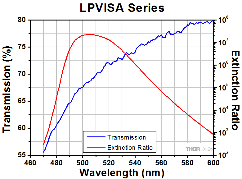 | - | ||||
| LPVISC050b | 510 - 800 nm | 520 - 740 nm | 530 - 640 nm | 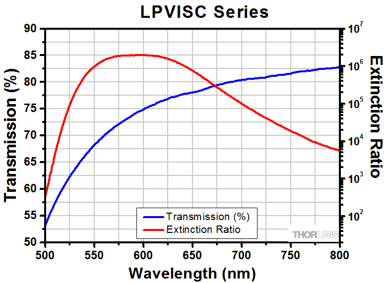 | - | ||||
| LPVIS050b | - | 550 - 1500 nm | 600 - 1200 nm |  | - | ||||
| LPNIR050b | 650 - 2000 nm | 750 - 1800 nm | 850 - 1600 nm |  | - | <20 arcmin | |||
| LPNIRA050 | 1.00 - 3.00 µm | 1.20 - 3.00 µm | - | 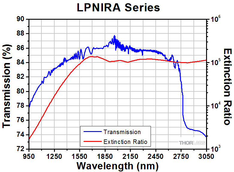 | - | 10 W/cm2 Continuous Block 25 W/cm2 Continuous Pass | 250 ± 65 µm | ||
| LPNIRD050c | - | 1.26 - 1.36 µm | - |  | Ravg < 0.25% for 1.26 - 1.36 µm | 90 ± 25 µm | |||
| LPNIRF050c | - | 1.50 - 1.60 µm | - |  | Ravg < 0.25% for 1.50 - 1.60 µm | ||||
| LPMIR050 | 1.50 - 5.00 µm | 2.00 - 4.50 µm | - |  | - | 200 ± 50 µm | |||
、低消光比")
 ズーム
ズーム| Table G2.1 Specifications | ||||||||
|---|---|---|---|---|---|---|---|---|
| Item # | Extinction Ratio Bandsa | Transmission and ER Graph | Parallelism | Laser Damage Threshold | Thickness (T) | Clear Aperture | ||
| >200:1 | >1000:1 | CW | Pulsed | |||||
| LPNIRB050 | 650 - 695 nm | 695 - 1100 nm |  | <0.5 arcmin | 10 W/cm2 Continuous Block 25 W/cm2 Continuous Pass | 0.006 J/cm2 (800 nm, 100 Hz, 36.4 fs, Ø189 µm) 0.1 J/cm2 (810 nm, 7.2 ns, 10 Hz, Ø0.216 mm) | 0.55 ± 0.1 mm | Ø11.4 mm (Ø0.45") |
| LPNIRC050 | - | 1.10 - 1.80 µm |  | - | ||||

 ズーム
ズーム| Table G3.1 Specifications | |||||||||
|---|---|---|---|---|---|---|---|---|---|
| Item # | Extinction Ratio Bandsa | Transmission and ER Graph | AR Coating at 0° AOI | Parallelism | Laser Damage Threshold | Optic Thickness (T) | Clear Aperture | ||
| >1000:1 | >10 000:1 | >100 000:1 | |||||||
| LPUV050-MP2 | 365 - 395 nm | 369 - 390 nm | 372 - 388 nm | | - | <20 arcmin | 10 W/cm2 Continuous Block 25 W/cm2 Continuous Pass | 220 ± 50 µm | Ø10.9 mm (Ø0.43") |
| LPVISA050-MP2 | - | 480 - 550 nm | - | | - | 280 ± 50 µm | |||
| LPVISC050-MP2 | 510 - 800 nm | 520 - 740 nm | 530 - 640 nm | | - | 200 ± 50 µm | |||
| LPVIS050-MP2 | - | 550 - 1500 nm | 600 - 1200 nm | | - | 260 ± 50 µm | |||
| LPNIR050-MP2 | 650 - 2000 nm | 750 - 1800 nm | 850 - 1600 nm | | - | 220 ± 50 µm | |||
| LPNIRA050-MP2 | 1.00 - 3.00 µm | 1.20 - 3.00 µm | - | | - | 250 ± 65 µm | |||
| LPNIRD050-MP2 | - | 1.26 - 1.36 µm | - | | Ravg < 0.25% for 1.26 - 1.36 µm | 90 ± 25 µm | Ø11.0 mm (Ø0.43") | ||
| LPNIRF050-MP2 | - | 1.50 - 1.60 µm | - | | Ravg < 0.25% for 1.50 - 1.60 µm | ||||
| LPMIR050-MP2 | 1.50 - 5.00 µm | 2.00 - 4.50 µm | - | | - | 200 ± 50 µm | Ø10.9 mm (Ø0.43") | ||

 ズーム
ズーム| Table G4.1 Specifications | ||||||||
|---|---|---|---|---|---|---|---|---|
| Item # | Extinction Ratio Bandsa | Transmission and ER Graph | Parallelism | Laser Damage Threshold | Optic Thickness (T) | Clear Aperture | ||
| >200:1 | >1000:1 | CW | Pulsed | |||||
| LPNIRB050-MP2 | 650 - 695 nm | 695 - 1100 nm | | <20 arcmin | 10 W/cm2 Continuous Block 25 W/cm2 Continuous Pass | 0.006 J/cm2 (800 nm, 100 Hz, 36.4 fs, Ø189 µm) 0.1 J/cm2 (810 nm, 7.2 ns, 10 Hz, Ø0.216 mm) | 0.55 ± 0.1 mm | Ø10.9 mm (Ø0.43") |
| LPNIRC050-MP2 | - | 1.10 - 1.80 µm | | - | ||||

 ズーム
ズーム| Table G5.1 Specifications | |||||||||
|---|---|---|---|---|---|---|---|---|---|
| Item # | Extinction Ratio Bandsa | Transmission and ER Graph | AR Coating at 0° AOI | Parallelism | Laser Damage Threshold | Thickness (T) | Clear Aperture | ||
| >1000:1 | >10 000:1 | >100 000:1 | |||||||
| LPUV100b | 365 - 395 nm | 369 - 390 nm | 372 - 388 nm | | - | <1 arcmin | 1 W/cm2 Continuous Block 5 W/cm2 Continuous Pass | 2.0 ± 0.2 mm | Ø22.5 mm (Ø0.88") |
| LPVISA100b | - | 480 - 550 nm | - | | - | ||||
| LPVISC100b | 510 - 800 nm | 520 - 740 nm | 530 - 640 nm | | - | ||||
| LPVIS100b | - | 550 - 1500 nm | 600 - 1200 nm | | - | ||||
| LPNIR100b | 650 - 2000 nm | 750 - 1800 nm | 850 - 1600 nm | | - | <20 arcmin | |||
| LPNIRA100 | 1.00 - 3.00 µm | 1.20 - 3.00 µm | - | | - | 10 W/cm2 Continuous Block 25 W/cm2 Continuous Pass | 250 ± 65 µm | ||
| LPNIRD100c | - | 1.26 - 1.36 µm | - | | Ravg < 0.25% for 1.26 - 1.36 µm | 90 ± 25 µm | |||
| LPNIRF100c | - | 1.50 - 1.60 µm | - | | Ravg < 0.25% for 1.50 - 1.60 µm | ||||
| LPMIR100 | 1.50 - 5.00 µm | 2.00 - 4.50 µm | - | | - | 200 ± 50 µm | |||
、低消光比")
 ズーム
ズーム| Table G6.1 Specifications | ||||||||
|---|---|---|---|---|---|---|---|---|
| Item # | Extinction Ratio Bandsa | Transmission and ER Graph | Parallelism | Laser Damage Threshold | Thickness (T) | Clear Aperture | ||
| >200:1 | >1000:1 | CW | Pulsed | |||||
| LPNIRB100 | 650 - 695 nm | 695 - 1100 nm | | <0.5 arcmin | 10 W/cm2 Continuous Block 25 W/cm2 Continuous Pass | 0.006 J/cm2 (800 nm, 100 Hz, 36.4 fs, Ø189 µm) 0.1 J/cm2 (810 nm, 7.2 ns, 10 Hz, Ø0.216 mm) | 0.55 ± 0.1 mm | Ø22.9 mm (Ø0.90") |
| LPNIRC100 | - | 1.10 - 1.80 µm | | - | ||||

 ズーム
ズーム| Table G7.1 Specifications | |||||||||
|---|---|---|---|---|---|---|---|---|---|
| Item # | Extinction Ratio Bandsa | Transmission and ER Graph | AR Coating at 0° AOI | Parallelism | Laser Damage Threshold | Optic Thickness (T) | Clear Aperture | ||
| >1000:1 | >10 000:1 | >100 000:1 | |||||||
| LPUV100-MP2 | 365 - 395 nm | 369 - 390 nm | 372 - 388 nm | | - | <20 arcmin | 10 W/cm2 Continuous Block 25 W/cm2 Continuous Pass | 220 ± 50 µm | Ø22.5 mm (Ø0.88") |
| LPVISA100-MP2 | - | 480 - 550 nm | - | | - | 280 ± 50 µm | |||
| LPVISC100-MP2 | 510 - 800 nm | 520 - 740 nm | 530 - 640 nm | | - | 280 ± 50 µm | |||
| LPVIS100-MP2 | - | 550 - 1500 nm | 600 - 1200 nm | | - | 260 ± 50 µm | |||
| LPNIR100-MP2 | 650 - 2000 nm | 750 - 1800 nm | 850 - 1600 nm | | - | 220 ± 50 µm | |||
| LPNIRA100-MP2 | 1.00 - 3.00 µm | 1.20 - 3.00 µm | - | | - | 250 ± 65 µm | |||
| LPNIRD100-MP2 | - | 1.26 - 1.36 µm | - | | Ravg < 0.25% for 1.26 - 1.36 µm | 90 ± 25 µm | |||
| LPNIRF100-MP2 | - | 1.50 - 1.60 µm | - | | Ravg < 0.25% for 1.50 - 1.60 µm | ||||
| LPMIR100-MP2 | 1.50 - 5.00 µm | 2.00 - 4.50 µm | - | | - | 200 ± 50 µm | |||

 ズーム
ズーム| Table G8.1 Specifications | ||||||||
|---|---|---|---|---|---|---|---|---|
| Item # | Extinction Ratio Bandsa | Transmission and ER Graph | Parallelism | Laser Damage Threshold | Optic Thickness (T) | Clear Aperture | ||
| >200:1 | >1000:1 | CW | Pulsed | |||||
| LPNIRB100-MP2 | 650 - 695 nm | 695 - 1100 nm | | <20 arcmin | 10 W/cm2 Continuous Block 25 W/cm2 Continuous Pass | 0.006 J/cm2 (800 nm, 100 Hz, 36.4 fs, Ø189 µm) 0.1 J/cm2 (810 nm, 7.2 ns, 10 Hz, Ø0.216 mm) | 0.55 ± 0.1 mm | Ø22.9 mm (Ø0.90") |
| LPNIRC100-MP2 | - | 1.10 - 1.80 µm | | - | ||||