 Products Home
パワーメーターキット
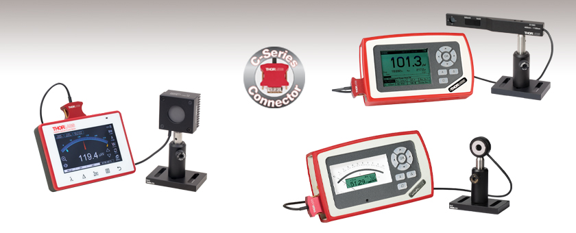
- Kits Include Console, Sensor, and Post Assembly
- Digital or Analog Console
- Wavelengths from 190 nm to 20 µm
- Powers from 500 pW to 10 W
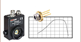
PM400K5
Digital Console with Thermal Sensor
PM130D
Digital Console with Slim Photodiode Sensor
PM120VA
Analog Console with Photodiode Sensor


Please Wait
| Power Meter Kit Specifications | ||||
|---|---|---|---|---|
| Item # | Power Range | Wavelength Range | Sensor Type | Console Type |
| PM120VA | 50 nW - 50 mW (200 - 450 nm) 50 nW - 20 mW (450 - 1100 nm) | 200 - 1100 nm | Si (S120VC) | Analog (PM100A) |
| PM120D | 50 nW - 50 mW | 400 - 1100 nm | Si (S120C) | Digital (PM100D) |
| PM400K1 | 50 nW - 50 mW | 400 - 1100 nm | Si (S120C) | Touchscreen Digital (PM400) |
| PM121D | 500 nW - 500 mW | 400 - 1100 nm | Si (S121C) | Digital (PM100D) |
| PM400K2 | 500 nW - 500 mW | 400 - 1100 nm | Si (S121C) | Touchscreen Digital (PM400) |
| PM130D | 500 pW - 500 mWa | 400 - 1100 nm | Slim Si (S130C) | Digital (PM100D) |
| PM400K3 | 500 pW - 500 mWa | 400 - 1100 nm | Slim Si (S130C) | Touchscreen Digital (PM400) |
| PM122D | 50 nW - 40 mW | 700 - 1800 nm | Ge (S122C) | Digital (PM100D) |
| PM400K4 | 50 nW - 40 mW | 700 - 1800 nm | Ge (S122C) | Touchscreen Digital (PM400) |
| PM125D | 2 mW - 10 W | 0.19 - 20 µm | Thermal (S425C) | Digital (PM100D) |
| PM400K5 | 2 mW - 10 W | 0.19 - 20 µm | Thermal (S425C) | Touchscreen Digital (PM400) |
| Power Meter Selection Guide |
|---|
| Sensors |
| Photodiode Power Sensors |
| Thermal Power Sensors |
| Thermal Position & Power Sensors |
| Pyroelectric Energy Sensors |
| Power Meter Consoles and Interfaces |
| Digital Handheld Console |
| Analog Handheld Console |
| Touchscreen Handheld Console |
| Dual-Channel Benchtop Console |
| USB Interfaces with External Readout |
| Complete Power Meters |
| Power Meter Bundles |
| Wireless Power Meters with Sensors |
| Compact USB Power Meters |
| Field Power Meters for Terminated Fibers |
特長
- コンソール、センサ、マウントが付属
- コンソールはCシリーズセンサに対応
- 大きくて読みやすいデジタルまたはアナログのディスプレイ
- ソフトウェアOptical Power Monitorを搭載したPCと接続するためのUSB2.0ポート(「ソフトウェア」タブ参照)
- 充電式バッテリ
- モニタ用信号はコンソールの3.5 mmジャックまたはSMA端子から出力(0~2 V)
- 再校正サービスをご提供
当社のパワーメーターキットは、コンソール、Cシリーズフォトダイオードまたはサーマルパワーセンサ、およびポストアセンブリから構成されています。アナログパワーメーターコンソールPM100Aが付属するPM120VAを除き、各キットのセンサは、デジタルパワーメーターコンソールPM100Dまたはタッチパネル式デジタルパワーメーターコンソールPM400のどちらかとのセットになっております。キットの種類については右表をご覧ください。
コンソールは3種類ともUSB 2.0端子を有し、それによりソフトウェアパッケージOptical Power Meterを搭載したPCからのリモート操作が可能です(詳細は「ソフトウェア」タブをご覧ください)。
アナログコンソールPM100A
アナログ式パワーメーターコンソールPM100Aは光パワーの絶対測定にも相対測定にも適しており、アナログ指針と補助的な液晶ディスプレイが備わっています。アナログ指針は光パワーの相対測定と小さい変動の観察に最適です。PM100AはすべてのCシリーズフォトダイオードセンサとサーマルセンサに対応しますが、焦電エネルギーセンサには対応しません。パワーメーターキットPM120VAにはコンソールPM100Aと電源ケーブル、センサS120VC、およびソフトウェアパッケージが収められたUSBフラッシュドライブが含まれています。 アナログコンソールPM100Aの機能の詳細については、「仕様」ならびに「PM100Aディスプレイ」タブ、または製品ページをご覧ください。
デジタルコンソールPM100D
デジタルパワー&エネルギーメーターコンソールPM100Dには、メニュー選択方式のコントロールパネル、バックライト付き4インチディスプレイ、データ保存用のSDカードスロットが備わっています。測定画面では、標準的なパワーとエネルギの読み取りに便利な数値表示、アナログ指針の模擬表示、経時的なパワー測定のグラフ、および統計量の表示などができます。さらにコンソールPM100Dには、ディテクタが視界内に置けない場合に使える、オーディオフィードバックが可能なチューニングモードがあります。詳細は「PM100Dディスプレイ」タブをご覧ください。このコンソールは、焦電エネルギーセンサを含む、当社のすべてのCシリーズのパワーまたはエネルギ測定用センサに対応しています。また、ソフトウェアパッケージが収められたUSBフラッシュドライブが付属します。 デジタルコンソールPM100Dの機能の詳細については、「仕様」ならびに「PM100Dディスプレイ」タブ、または製品ページをご覧ください。
タッチパネル式デジタルコンソールPM400
タッチパネル式デジタルパワー&エネルギーメーターコンソールPM400には、マルチタッチ技術を用いた4.3インチディスプレイが備わっています。ユニット前面にある静電容量方式のボタンを使用すると、光源の波長やスペクトルの設定、お客様が設定した参照値からのパワーの変化を表示するデルタモードへの切り換え、ゼロ点調整、およびデバイスのメインメニューへの切り換えができます。測定値の校正用に予めプログラミングされた光源の波長やスペクトルに加え、パワー測定における外部機器(フィルタやビームスプリッタなど)の影響を補正するために、お客様の方でそれらの減衰量に関するデータ(最大12個まで)やデータファイルを入力し、保存することが可能です。
14ピン補助入力端子にはお手持ちの温湿度センサを接続できるほか、4つのプログラム可能なI/Oポートがあり、シャッタ、インターロックデバイス、レーザ用警告灯、一般的な研究機器などを制御するのに使用することできます(詳細については「ピン配列」タブをご覧ください)。また、2.5 mmステレオ(3P)ジャックには、サーミスタ温度プローブTSP-THが取り付け可能です。このコンソールもPM100Dと同様に当社の全てのCシリーズセンサに対応します。 タッチパネル式デジタルコンソールPM400の機能の詳細については、「仕様」や「PM400ディスプレイ」タブ、または製品ページをご覧ください。
パワーメータならびにセンサのその他のオプション
こちらのキットに含まれるパワーメーターコンソールならびにセンサは単体でもお買い求めいただけます。また、当社ではハンドヘルド操作ならびにBluetoothまたはUSB接続を使用したリモート操作の両方用に設計されたワイヤレス機能付きパワーメータ、およびPCでのソフトウェアによる操作用に設計された小型USBパワーメータもご用意しております。
再校正サービス
当社ではフォトダイオードならびにサーマルパワーメーターセンサとコンソールの再校正サービスを提供しています。当社ではセンサとコンソールをセットで再校正されることをお勧めしておりますが、単体で再校正を行うことも可能です。 コンソールのみの再校正も承ります。再校正サービスの詳細につきましては、当社までお問い合わせください。
PM100Aの製品ページはこちらをクリックしてご覧ください。
| PM100A Specifications | |
|---|---|
| Photodiode Sensor Input (Current) | |
| Measurement Ranges | 6 Decades; 50 nA - 5 mA |
| Units | W |
| Accuracy | ±0.2% of Full Scale (5 µA - 5 mA) ±0.5% of Full Scale (50 nA) ±3% Full Scale Analog Meter |
| Bandwidth | DC to 100 kHz, Dependent on Sensor and Settings |
| Analog Output | |
| Connector | SMA |
| Voltage Range | 0 - 2 V |
| Bandwidth | Up to 100 kHz, Dependent on Sensor and Settings |
| Accuracy | ±3% |
| General | |
| Sensor Input | Female DB9 for C-Series Connectors |
| Display | Analog Needle with 132 x 32 pixel LCD Readout |
| Display Update Rate | 20 Hz |
| Display Screens | Numerical, Relative Measurements, Tuning, Statistics, Mechanical Analog Needle |
| Memory Card | N/A |
| A/D Converter | 16 bit |
| Computer Connectivity | USB 2.0, Mini USB |
| Battery | Li-Polymer 3.7 V, 1300 mAh; up to 8 hrs of Operation |
| Dimensions | 7.2" x 4.3" x 1.6" (183 mm x 109 mm x 40 mm) |
| Operating / Storage Temp | 0 to 40 °C / -40 to 70 °C |
| Mounting | Kickstand, 1/4"-20 Mounting Hole |
PM100Dの製品ページはこちらをクリックしてご覧ください。
| PM100D Specifications | |
|---|---|
| Photodiode Sensor Input (Current) | |
| Measurement Ranges | 6 Decades; 50 nA - 5 mA |
| Units | W, dBm, W/cm2, A |
| Accuracy | ±0.2% of Full Scale (5 µA - 5 mA) ±0.5% of Full Scale (50 - 500 nA) |
| Bandwidth | DC to 100 kHz, Dependent on Sensor and Settings |
| Thermopile Sensor Input (Voltage) | |
| Measurement Ranges | 4 Decades; 1 mV - 1 V |
| Units | W, dBm, W/cm2, V |
| Accuracy | ±0.5% of Full Scale (10 mV - 1 V) ±1% of Full Scale (1 mV) |
| Bandwidth | DC to 10 Hz, Dependent on Sensor and Settings |
| Time Constant Correction | 1 - 30 s |
| Analog Output | |
| Connector | SMA |
| Voltage Range | 0 - 2 V |
| Bandwidth | Up to 100 kHz, Dependent on Sensor and Settings |
| Accuracy | ±3% |
| General | |
| Sensor Input | Female DB9 for C-Series Connectors |
| Display | 3.2" x 2.4" (81.4 mm x 61 mm), 320 x 240 pixels |
| Display Update Rate | 20 Hz |
| Display Screens | Numerical, Bar Graph, Trend Graph, Statistics, Simulated Analog Needle |
| Memory Card | SD, 1 GB |
| A/D Converter | 16 bit |
| Computer Connectivity | USB 2.0, Mini USB |
| Battery | Li-Polymer 3.7 V, 1300 mAh; up to 8 hrs of Operation |
| Dimensions | 7.2" x 4.3" x 1.6" (183 mm x 109 mm x 40 mm) |
| Operating / Storage Temp | 0 to 40 °C / -40 to 70 °C |
| Mounting | Kickstand, 1/4"-20 Mounting Hole |
| Specifications | |
|---|---|
| Compatible Detectors | Thorlabs' C-Series Photodiode, Thermal, and Pyroelectric Sensors Photodiodes up to 5 mA, Thermopiles up to 1 V, and Pyroelectric Detectors up to 100 V |
| Display | |
| Type | 4.3" TFT, WQVGA, 400 x 272 Pixels, 16 Bit Color |
| Viewing Area | 95 mm x 54 mm |
| Update Rate (Max) | 10 Hz Numerical, 25 Hz Analog Simulation |
| Format | Numerical, Bar Graph, Trend Graph, Statistics, and Simulated Analog Needle |
| Backlight | LED, Adjustable |
| Features | Projected Capacitive Touchscreen and Buttons, Support Stand, Rubberized Outside, 2 x M3 Threaded Inserts for Mounting on Back Side |
| Analog Output | |
| Connector | 3.5 mm Mono Audio (2P) Jack, Adapter to BNC Included |
| Signal | Amplified Input Signal - Not Corrected |
| Voltage Range | 0 to 2 V |
| Accuracy | ±3% |
| Bandwidth | Up to 100 kHz, Dependent on Sensor and Settings |
| Auxiliary Input/Output | |
| Connector | 2 x 7 Pins, 0.1" Socket, Top Side |
| Function | 4 x GPIO 2 x 10 bit ADC for External Temperature, Relative Humidity Sensor +3.3 V, +/- 2.5 V (100 mA Max) |
| Temperature Sensor Internal to C-Series Optical Sensora | |
| Temperature Sensor Type | Thermistor |
| Temperature Measurement Range | -10 °C to 80 °C |
| External Temperature Sensor | |
| Supported Temperature Sensor | Thermistor NTC 0.1 - 100 kΩ, B-Value 1000 - 9999 K |
| Temperature Measurement Range | -10 °C to 80 °C (with TSP-TH) |
| Connector | 2.5 mm Stereo Audio (3P) Jack |
| Sound | |
| Type | Internal Speaker |
| Function | Laser Tuning Support, Console Function Support |
| Memory | |
| Type | NAND Flash |
| Size | 4 GB |
| Interfaces | |
| Type | USB 2.0 |
| Connector | Mini-B USB |
| Power Management | |
| Battery | LiPo 3.7 V 2600 mAh |
| Charger | Built In; Charging Current: 0.5 / 1 A |
| Power Connector | Mini USB |
| General | |
| Operating Temperature Rangeb | 0 to 40 °C |
| Storage Temperature Range | -40 to 70 °C |
| Dimensions | 136 mm x 96 mm x 29 mm |
| Weight | 0.35 kg |
Power Meter Console Displays
Click on a the console item #s below to expand the corresponding section that provides details on the display for each.
PM100A
| PM100A Display | |
|---|---|
| Standard Absolute Measurements | Relative Measurements |
 |
 |
| This display shows the current absolute power values on both the mechanical needle and the LCD display. | Shows positive or negative power deviation from an initially zeroed position (needle in middle position). The offset and the absolute power value will be displayed in two sub displays in negative presentation. |
| Power Tuning with Sound Support | Statistics Screen |
 |
 |
| This display shows the maximum reached power level. The level can be reset to the actual power level. |
A display showing the current, min, max, and average power. All items can be reset to restart data sampling. |
| Wavelength Setting | |
 |
|
| Configuration screen to set the wavelength of the incident beam. Easy switching between 9 user preconfigurable wavelengths. | |
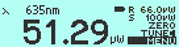
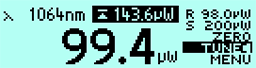
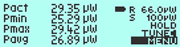
PM100D
| PM100D Display | |||
|---|---|---|---|
| Numeric Screen (Power Mode) | Numeric Screen (Energy Mode) | ||
 |
This display combines a clear, numerical 4-digit read out of the optical power, a bar graph function with zooming capabilities, and configurable sub displays. | 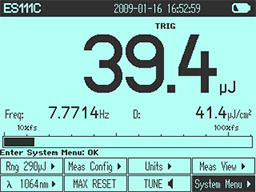 |
A display with the same option as on the left for optical energy read outs. |
| Trend Graph (Power Mode) | Needle Tuning (Power Mode) | ||
 |
For laser tuning and beam alignment to visualize changes and trends together with an additional 4-digit numerical value of the absolute power. | 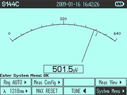 |
A display imitating an analog needle together with an additional 4-digit numerical value for laser tuning tasks. A special feature is a resettable max hold indicator and a shiftable tuning sound. |
| Pulse Chart (Energy Mode) | Statistics Screen (Power Mode) | ||
 |
Like the Trend Graph (Power Mode), this shows changes and trends together with an additional 4-digit numerical value of the absolute energy of incident beam pulses. | 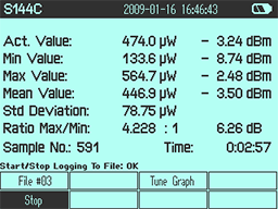 |
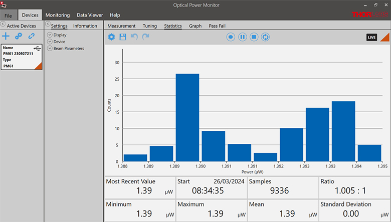
The statistics display shows the actual, minimum, maximum and mean value in linear and logarithmic representation; further the standard deviation, the max/min ratio, the number of samples and the elapsed time. |
Common Display Elements
- Header line with sensor information, date/time, and battery state
- Status line with warning annunciators
- Bar graph and configurable left and right sub display areas to display a minimum and a maximum value or a ratio of both values (numerical screen only)
- Tool tip text above the menu
- Easily accessible menu via buttons
PM400
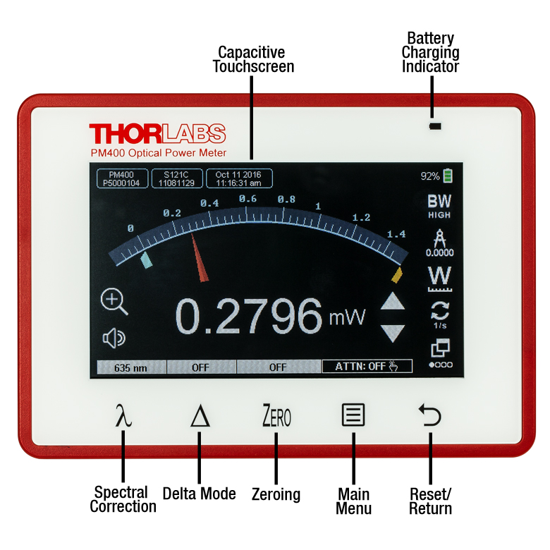
Click to Enlarge
The Front Panel of the Touchscreen Power Meter Console
Touchscreen Power Meter Console Front Panel
Thorlabs' PM400 Power Meter Console features a front panel with several key elements, as shown in the photo to the right. The projected capacitive touchscreen and buttons are sensitive enough to allow smooth operation even when the user wears cotton, latex, or nitrile gloves, but durable enough to be cleaned with standard screen cleaning solvents.
- Capacitive Touchscreen: The capacitive touchscreen allows the user to control the console functions with finger taps and swipes. Features include numerical displays of power and energy measurements, logging of long-term measurements, settings for a calibration wavelength or a preset attenuation value, and temperature monitoring. The user can switch measurement views by swiping one finger over the screen to the left or right, or by tapping the window icon in the lower right corner of the screen. More details on the measurement options are provided below.
- Spectral Correction Button: This button opens a screen where the user can quickly select or save up to 12 measurement wavelengths. The PM400 will use this wavelength setting in conjunction with the calibration data recorded in the connector of Thorlabs' power and energy sensors in order to provide a calibrated optical power or energy reading. The selected wavelength is displayed above the button.
- Delta Mode: In delta mode, the console will display the power or energy relative to a user selected setpoint. Pressing this button saves the current power or energy reading as the reference value, and subsequent measurements will be displayed as the difference between the actual value and the reference. The reference value is displayed above this button when Delta Mode is active.
- Zeroing: Quickly set the current power or energy value as the zero point for subsequent measurements. The measured power or energy when the console is zeroed will be displayed above the Zero button.
- Main Menu: This button provides quick access to the main menu. From here, the user can access a submenu to set the parameters for long-term power measurements, device settings, the file manager, sensor info, and the laser calculator. Details are provided below.
Additional Features
In addition to allowing users to select different measurement modes and settings, the PM400 incorporates other features to allow users to customize the interface.
- Language Settings: English, French, German, and Chinese can be selected.
- Display Brightness and Contrast: In addition to adjusting these settings, the user can choose whether to have the display show white text on a black background, or black text on a white background.
- Laser Tuning Sound: The console plays an audible tone to aid in identifying when peak power is achieved while tuning a laser. The console will beep repeatedly, with the frequency of the beep increasing as the measured power increases.
- Programmable I/O Ports: The PM400 features four programmable I/O ports for controlling shutters, interlocks, laser warning lights, etc.
The Touchscreen Display
The screenshots below provide an overview of some of the measurement views, measurement settings, functions, and calculators accessible through the touchscreen display.
Numerical Display
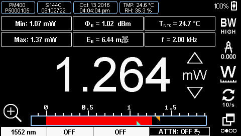
| Subpanel Display Options | ||
|---|---|---|
| Photodiode Sensors | Thermal Sensors | Pyroelectric Sensors |
| Current (IDET) | Voltage (VDET) | Voltage (VDET) |
| Power (Φe) | Power (Φe) | Energy (WDET) |
| Power in dBm (Φe) | Power in dBm (Φe) | N/A |
| Max | Max | Max |
| Min | Min | Min |
| Ratio (Max/Min) | Ratio (Max/Min) | Ratio (Max/Min) |
| Sensor Temperaturea | Sensor Temperaturea | N/A |
| Frequency | Frequency | Frequency |
| External NTC Temperature | External NTC Temperature | External NTC Temperature |
| Irradiance (Ee) | Irradiance (Ee) | Fluence (He) |
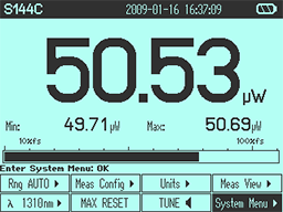
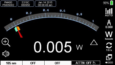
The numerical display shows a digital measurement of the power or energy with a bar graph along the bottom. The orange and blue triangles on the bar graph show the min and max values detected during the measurement. To reset the min and max values, press the reset button on the front panel. The six rectangular subpanels immediately above the power or energy measurement are configurable displays, allowing the user to select which parameters to view. The Subpanel Display Options table provides a summary of available settings for each style of detector.
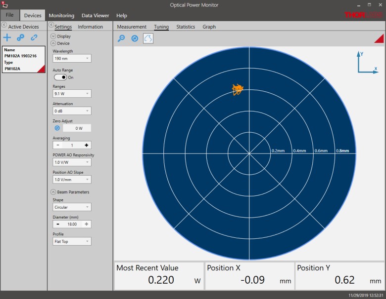
Simulated Analog Needle
Measurements can be viewed with a simulated analog needle. The orange and blue marks are indicators for the max and min measured power, and the scale can be zoomed by a factor of 10. Icons down the side of the screen allow the user to set the bandwidth, adjust the resolution of the digital value at the bottom of the display, change units, adjust the display update rate or change screens.
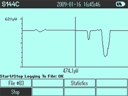
Graph View
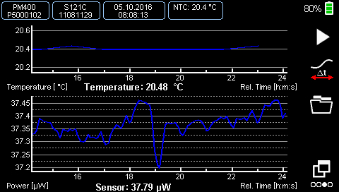
In the graph view, the user can monitor the optical power or energy of a source as it changes over time. A second, optional display can be added that shows the readout from a connected temperature sensor (the upper graph in the screenshot above). Icons on the side of the window allow the user to start and stop the measurement, scroll through the data, and open the folder where the measurement is saved.
Statistics Display
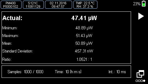
In the statistics display, the user can start a sequential measurement. The sample rate and duration can be adjusted from the Capture Settings screen, accessible from the main menu. The bottom bar of the display shows the number of measurements taken, total elapsed time since the measurements were started, and the measurement interval. The main part of the display shows statistics for the accumulated measurements, including the minimum, maximum, mean, and standard deviation.
Spectral Correction
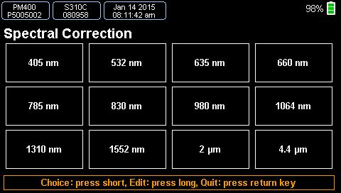
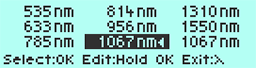
This mode can be entered by pressing the λ symbol on the front panel. The unit can store up to 12 preset spectral correction entries, editable by the user. In their simplest form, these entries can consist of a single user-entered wavelength that will be used in conjunction with the NIST-traceable calibration data from a Thorlabs' sensor to produce a calibrated power measurement. Alternatively, each entry can be a .csv file with the source spectrum that has been uploaded and saved. When a spectral correction entry is selected, the entry name will be displayed in the field above the spectral correction button.
Attenuation Correction
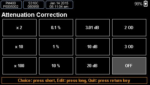
External devices within a setup, such as a filter or beamsplitter, may be needed to attenuate the signal being measured. The attenuation correction function allows the PM400 to display a power reading that accounts for these sources of attenuation. Attenuation values can be assigned as a multiplier (e.g. x2), in percent, in dB, or in OD (optical density). Alternatively, complete filter transmission curves can be uploaded and saved. Up to 12 different attenuation settings can be programmed and stored.
Main Menu
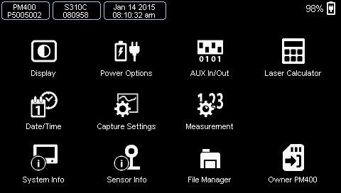
The PM400 main menu allows access to device features including the screen brightness, the menus to set the parameters for power, energy, and temperature measurements, a screen for calculating laser pulse characteristics, and a unit converter.
Capture Settings
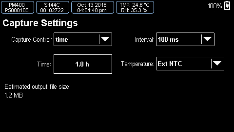
This screen allows the user to set the parameters for taking data. User-selectable settings include manual or automatic data acquisition, the exposure time, the number of samples, and the capture interval. It also allows the temperature logging parameters to be set. Once all of the settings are selected, this screen will return an estimated file size so that the user can ensure there is enough free memory on the device. In the case of manual operation (the user manually starts and stops the measurement), the estimated output file size will be the rate at which memory is used up as the data is collected.
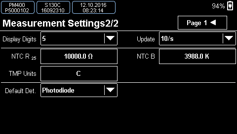
Sensor Measurement Settings

This screen allows the user to view sensor-dependent content, adjust common settings such as wavelength, attenuation, mode, etc., and enter beam parameters.
Temperature Sensor Settings
If an external temperature sensor is hooked up to the PM400, the user can adjust the parameters here.
Laser Calculator and Unit Converter
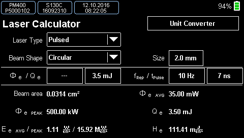
The PM400 has several calculators. The laser calculator screen allows the user to calculate laser beam parameters based on available inputs. A unit converter provides quick conversions between Watts and dBm or between wavelength, frequency, wavenumbers, and photon energy.
パワーメーターコンソールPM100AならびにPM100D
光学センサーヘッド入力部
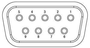
Dサブメス型9ピン
| Connection | ||
|---|---|---|
| Pin | PM100A | PM100D |
| 1 | +5 V (100 mA Max Current from This Pin) | |
| 2 | DO NOT USEa | |
| 3 | AGND (Analog Ground): Photodiode Ground (Anode), Thermal and Pyroelectric Sensor Ground | |
| 4 | Photodiode Cathode | |
| 5 | Not Connected | Pyro-Electric Sensor + |
| 6 | DGND (Digital Ground) | |
| 7 | Present: Connect this Pin via a 1 kΩ to 10 kΩ Resistor to Pin 3 (AGND) to Enable a Custom Sensor | |
| 8 | Thermal Sensor + | |
| 9 | Not Connected | |
アナログ出力
0 ... 2 V、
SMAメス型
コンピュータ接続
USB Mini-B

リモート操作ならびに充電用のUSB Mini-B、
ケーブルが付属
パワーメーターコンソールPM400
光学センサーヘッド入力部
Dサブメス型9ピン
| Pin | Connection |
|---|---|
| 1 | +5 V (100 mA Max Current from This Pin) |
| 2 | DO NOT USEa |
| 3 | AGND (Analog Ground): Photodiode Ground (Anode), Thermal and Pyroelectric Sensor Ground |
| 4 | Photodiode Cathode |
| 5 | Pyroelectric Sensor + |
| 6 | DGND (Digital Ground) |
| 7 | Present: Connect this Pin via a 1 kΩ to 10 kΩ Resistor to Pin 3 (AGND) to Enable a Custom Sensor |
| 8 | Thermal Sensor + |
| 9 | Not Connected |
補助コネクタ

14ピンデュアルインラインソケット、ピッチ2.54 mm
| Pin | Connection |
|---|---|
| 1 | Ground |
| 2 | +3.3 VDC, 0.1 A |
| 3 | Do Not Use (No Function) |
| 4 | ADC Current In (Humidity Sensor) |
| 5 | Temp / Humidity Detection Module |
| 6 | ADC Current In (Temperature Sensor) |
| 7 | GPIO 02 |
| 8 | GPIO 01 |
| 9 | GPIO 03 |
| 10 | GPIO 04 |
| 11 | Ground |
| 12 | + 2.5 VDC, 0.05 A |
| 13 | Ground |
| 14 | -2.5 VDC, 0.05 A |
コンピュータ接続
USB Mini-B
リモート操作ならびに充電用のUSB Mini-B、
ケーブルが付属
アナログ出力

0 to 2 V、
3.5 mmモノオーディオ(2P)ジャック
温度センサ入力
2.5 mmステレオオーディオ(2P)ジャック、NTC用
対応するパワーメータ
- コンソール
- アナログパワー&エネルギーメーターコンソールPM100A
- デジタルパワー&エネルギーメーターコンソールPM100D
- 静電容量タッチパネル式パワー&エネルギーメーターコンソールPM400
- 2チャンネルベンチトップ型光パワー&エネルギーメーターコンソール(バージョン4.0以降)PM5020
- パワーメータ
- Bluetooth®方式ワイヤレスハンドヘルド型パワーメータPM160、PM160T、PM160T-HP
- 小型USBパワーメータPM16シリーズ
- 光ファイバパワーメータM60およびPM61(バージョン6.0以降)
- インターフェイス
- PM101シリーズパワーメーターインターフェイス、外部読み出しタイプ(バージョン2.0以降)
- PM102シリーズパワーメーターインターフェイス、外部読み出しタイプ(バージョン2.1以降)
- PM103シリーズパワーメーターインターフェイス、外部読み出しタイプ(バージョン3.0以降)
- USB接続デジタルパワー&エネルギーメーターPM100USB
対応する消光比メータ
- 消光比メータERM2xxシリーズ
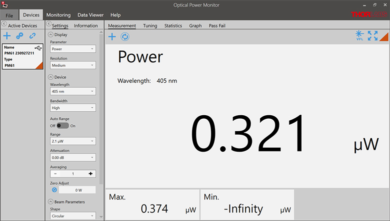
Optical Power Monitor
このGUIソフトウェアOptical Power Monitorには、パワーの測定、最大8台までのパワーメータの読み取り、およびワイヤレスでのリモート操作といった機能があります。
特定のソフトウェア機能の詳細については、こちらからダウンロードいただけるユーザーマニュアルをご覧ください。
旧世代のPower Meter Softwareについてはこちらのソフトウェアページをご覧ください。
PM101シリーズパワーメータはバージョン2.0以降のみに対応します。PM102シリーズパワーメータはバージョン2.1以降のみに対応します。PM103シリーズパワー&エネルギーメータはバージョン3.0以降のみに対応します。コンソールPM5020はバージョン4.0以降にのみ対応します。パワーメータ―シリーズPM60およびPM61はバージョン6.0以降のみに対応します。
タッチパネル型、ハンドヘルド型、およびUSB接続型光パワーメータ用のGUIソフトウェアOptical Power Monitor
特長
- 最大8台までのパワーメータを同時操作
- リアルタイムでの測定値の記録と解析
- 直感的なアナログ表示とグラフモード
- 設定可能な長時間のデータロギング機能
- サーマル位置&パワーセンサによる位置測定もサポート
- USBおよびBluetooth®接続に対応
Optical Power MonitorのGUIを用いると、USB、RS232またはBluetooth®ワイヤレスa接続により最大8台までのパワーメータのシームレスな制御が可能です。パワーメータ用の最新のソフトウェア、ファームウェア、ドライバ、およびユティリティはこちらからダウンロードできます。
このGUIパッケージには、多チャンネルのデータ測定と解析機能が組み込まれています。インターフェイスは使いやすさを考慮した設計になっています。表示色を最小限にし、輝度も低く抑えているため、レーザ用保護メガネを着用しながらの暗い実験室での使用に適しています。測定データはアナログ針、デジタル数値、線グラフ、あるいは棒グラフでリアルタイムに表示できます。連続したログデータや短時間での測定結果は、後でデータの閲覧や解析を行うために記録することできます。組み込まれている統計モードでは測定データの解析を行い、予め設定された測定周期で新しい測定値を反映させ、連続的に更新を行います。当社のサーマル位置&パワーセンサを用いたビーム位置測定にも対応します。
このソフトウェアパッケージOptical Power MonitorでGUIをインストールすると、すぐにタッチパネル型、ハンドヘルド型、またはUSB接続型のパワーメータの制御にご使用いただけます。対応するパワーメータのファームウェアの更新も可能です。当社のパワー&エネルギーメーターコンソールに使用できる、LabVIEW、Visual C++、Visual C#を用いたプログラム例やドライバが、ソフトウェアと一緒にインストールされます。詳細についてはマニュアルをご覧ください。
なお、このOptical Power Monitor Softwareは、Power Meter Utilities Softwareとは異なるドライバを使用しているのでご注意ください。当社では最新のドライバTLPM.dllのご使用をお勧めします。従来のPower Meter Softwareや以前のドライバPM100D.dllを使用したカスタムソフトウェアを使用したい方のために、2つのバージョンのドライバを簡単に切り替えられるプログラムPower Meter Driver Switcherが付属しています。
a. パワーメータPM160、PM160TおよびPM160T-HPにBluetooth®機能が付いています。


Click to Enlarge
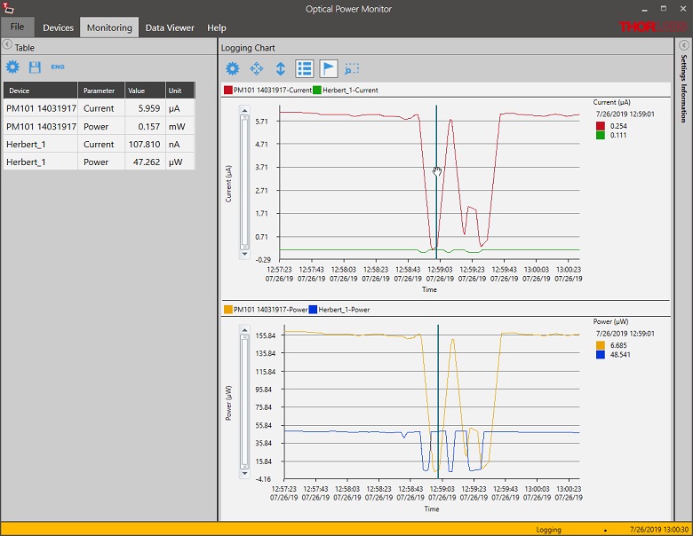
Figure 149F データロギング
長時間測定と最大8台までのパワーメータの同時記録が可能です。データは後処理により.csv形式で保存されますが、測定結果はリアルタイムでグラフ表示されます。
パルスレーザ:パワーとエネルギーの計算

パルスレーザからの放射光が、使用するデバイスや用途に適合するかどうかを判断する上で、レーザの製造元から提供されていないパラメータを参照しなければならない場合があります。このような場合、一般には入手可能な情報から必要なパラメータを算出することが可能です。次のような場合を含めて、必要な結果を得るには、ピークパルスパワー、平均パワー、パルスエネルギ、その他の関連するパラメータを必要とすることがあります。
- 生物試料を損傷させないように保護する
- フォトディテクタなどのセンサにダメージを与えることなくパルスレーザ光を測定する
- 物質内で蛍光や非線形効果を得るために励起を行う
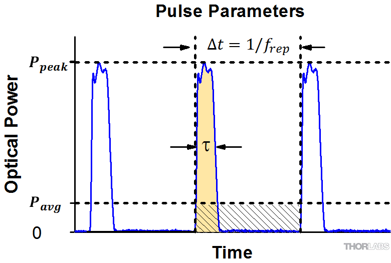
パルスレーザ光のパラメータはFigure 170AおよびTable 170Bに示します。参照用として、計算式の一覧を以下に示します。資料を ダウンロードしていただくと、これらの計算式のほかに、パルスレーザ光の概要、異なるパラメータ間の関係性、および計算式の適用例がご覧いただけます。
計算式 | ||||
 | 、 |  | ||
 | ||||
 | ||||
 | ||||
平均パワーから算出するピークパワー、ピークパワーから算出する平均パワー : | ||||
 | 、 |  | ||
| 平均パワーおよびデューティーサイクルから算出するピークパワー*: | ||||
 | *デューティーサイクル( ) はレーザのパルス光が放射されている時間の割合です。 ) はレーザのパルス光が放射されている時間の割合です。 | |||
Click to Enlarge
Figure 170A パルスレーザ光の特性を記述するためのパラメータを、上のグラフとTable 170Bに示します。パルスエネルギ (E)は、パルス曲線の下側の黄色の領域の面積に対応します。このパルスエネルギは斜線で表された領域の面積とも一致します。
| Table 170B パルスのパラメータ | |||||
|---|---|---|---|---|---|
| パラメータ | シンボル | 単位 | 説明 | ||
| パルスエネルギ | E | ジュール[J] | レーザの1周期中に放射される1パルスの全放射エネルギ。 パルスエネルギはグラフの黄色の領域の面積に等しく、 これは斜線部分の面積とも一致します。 | ||
| 周期 | Δt | 秒 [s] | 1つのパルスの開始から次のパルスの開始までの時間 | ||
| 平均パワー | Pavg | ワット[W] | パルスとして放射されたエネルギが、1周期にわたって 均一に広がっていたと仮定したときの、 光パワーの大きさ(光パワー軸上の高さ) | ||
| 瞬時パワー | P | ワット[W] | 特定の時点における光パワー | ||
| ピークパワー | Ppeak | ワット [W] | レーザから出力される最大の瞬時パワー | ||
| パルス幅 |  | 秒 [s] | パルスの開始から終了までの時間。一般的にはパルス形状の 半値全幅(FWHM)を基準にしています。 パルス持続時間とも呼ばれます。 | ||
| 繰り返し周波数 | frep | ヘルツ [Hz] | パルス光が放射される頻度を周波数で表示した量。 周期とは逆数の関係です。 | ||
計算例
下記のパルスレーザ光を測定するのに、最大入力ピークパワーが75 mW
のディテクタを使用するのは安全かどうかを計算してみます。
- 平均パワー: 1 mW
- 繰り返し周波数: 85 MHz
- パルス幅: 10 fs
1パルスあたりのエネルギは、

と低いようですが、ピークパワーは、

となります。このピークパワーはディテクタの
最大入力ピークパワーよりも5桁ほど大きく、
従って、上記のパルスレーザ光を測定するのに
このディテクタを使用するのは安全ではありません。
当社では、幅広いパワーメータ&エネルギーメータ用コンソールやパワーセンサ・エネルギーセンサを操作するためのインターフェイスを取り揃えています。 主な仕様は下記でご覧いただけるので、お客様の用途に適したモデルをお選びいただけます。 下記のほかに、センサ内蔵のワイヤレスパワーメータや小型USBパワーメータもご用意しております。
当社のパワーメータ等用のコンソールやインターフェイスは、Cシリーズのセンサとお使いいただく場合は接続したセンサの種類を自動的に認識し、電流値とそれに応じた電圧値を測定します。 Cシリーズのセンサは、コネクタ内に感度特性の校正データが保存されています。 コンソールは、入射波長に対応する感度の値を読み出し、パワーもしくはエネルギの測定値を計算します。
- フォトダイオードセンサは、入射光の光パワーと波長によって決まる電流を流します。 この電流は、トランスインピーダンスアンプに送られ、このアンプから入力電流に比例した電圧が出力されます。 フォトダイオードの感度は波長に依存するため、正確なパワーの測定値を得るためには、コンソールに正しい波長を入力する必要があります。 コンソールは、接続されたセンサから、入力された波長における感度を読み取り、測定した光電流から光パワーを計算します。
- サーマルセンサは、入射された光パワーに比例した電圧を送ります。 測定されたセンサの出力電圧とその感度特性に基づいて、コンソールは入射した光パワーを計算します。
- エネルギーセンサは焦電効果に基づいています。 したがって、エネルギーセンサは、パルスエネルギに比例したピーク電圧を送ります。 エネルギーセンサが認識されると、コンソールはピーク電圧ディテクタを活用し、センサの感度特性からパルスエネルギが計算されます。
コンソールやインターフェイスはセンサが出力する電流や電圧を表示する機能も備えています。 または、測定された電流や電圧をアナログ出力で得ることもできます。
コンソール
| Item # | PM100A | PM100D | PM400 | PM5020 |
|---|---|---|---|---|
| (Click Photo to Enlarge) | 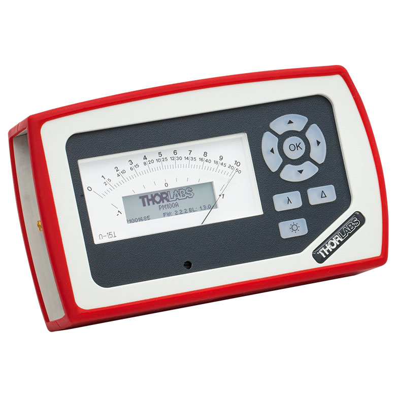 | 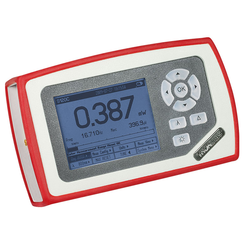 | 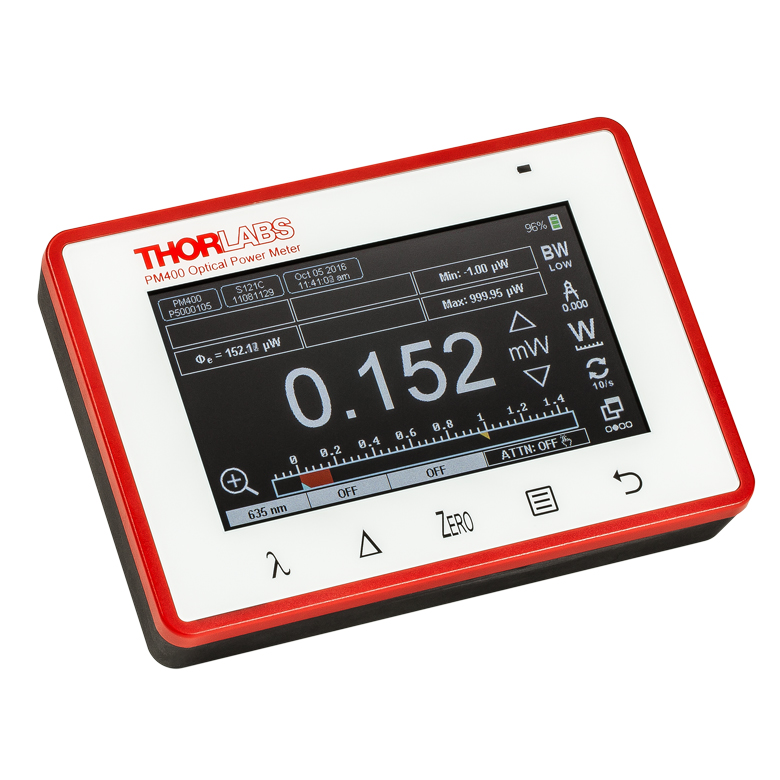 | 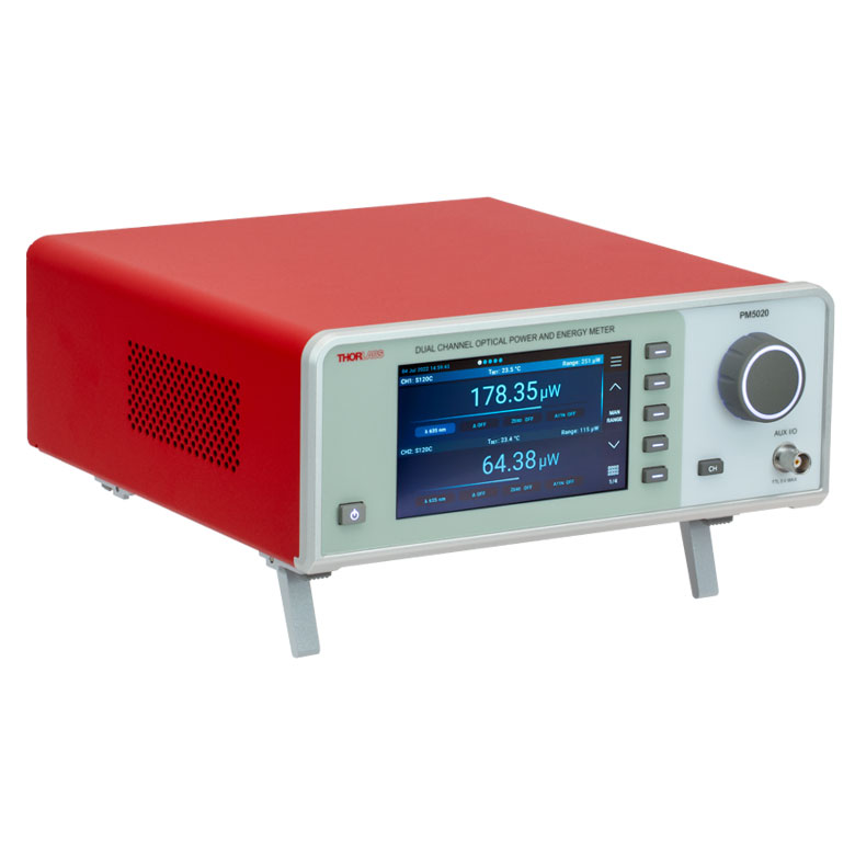 |
| Key Features | Analog Power Measurements | Digital Power and Energy Measurements | Digital Power and Energy Measurements, Touchscreen Control | Dual Channel |
| Compatible Sensors | Photodiode and Thermal Power | Photodiode Power, Thermal Power, and Pyroelectric Energya | Photodiode Power, Thermal Power, Thermal Power and Position, and Pyroelectric Energya | Photodiode Power, Thermal Power, Thermal Power and Position, and Pyroelectric Energy |
| Housing Dimensions (H x W x D) | 7.24" x 4.29" x 1.61" (184 mm x 109 mm x 41 mm) | 7.09" x 4.13" x 1.50" (180 mm x 105 mm x 38 mm) | 5.35" x 3.78" x 1.16" (136.0 mm x 96.0 mm x 29.5 mm) | 9.97" x 4.35" x 11.56" (253.2 mm x 110.6 mm x 293.6 mm) |
| Channels | 1 | 2 | ||
| External Temperature Sensor Input (Sensor not Included) | - | - | Readout and Record Temperature Over Time | Readout and Record Temperature Over Time |
| External Humidity Sensor Input (Sensor not Included) | - | - | Readout and Record Humidity Over Time | Readout and Record Humidity Over Time |
| Input/Output Ports | - | 4 GPIO, Programmable | 4 Configurable Digital I/O Channels | |
| Shutter Control | - | - | - | Support for SH05R(/M) or SH1(/M) Optical Shutter with Interlock Input |
| Fan Control | - | - | - | |
| Source Spectral Correction | - | - | ||
| Attenuation Correction | - | - | ||
| External Trigger Input | - | - | - | |
| Display | ||||
| Type | Mechanical Needle and LCD Display with Digital Readout | 320 x 240 Pixel Backlit Graphical LCD Display | Protected Capacitive Touchscreen with Color Display | |
| Dimensions | Digital: 1.9" x 0.5" (48.2 mm x 13.2 mm) Analog: 3.54" x 1.65" (90.0 mm x 42.0 mm) | 3.17" x 2.36" (81.4 mm x 61.0 mm) | 3.7" x 2.1" (95 mm x 54 mm) | 4.32" x 2.43" (109.7 mm x 61.6 mm) |
| Refresh Rate | 20 Hz | 10 Hz (Numerical) 25 Hz (Analog Simulation) | 25 Hz | |
| Measurement Viewsb | ||||
| Numerical | ||||
| Mechanical Analog Needle | - | - | - | |
| Simulated Analog Needle | - | |||
| Bar Graph | - | |||
| Trend Graph | - | |||
| Histogram | - | - | - | |
| Statistics | ||||
| Memory | ||||
| Type | - | SD Card | NAND Flash | SD Card |
| Size | - | 2 GB | 4 GB | 8 GB |
| Power | ||||
| Battery | LiPo 3.7 V 1300 mAh | LiPo 3.7 V 2600 mAh | - | |
| External | 5 VDC via USB or Included AC Adapter | 5 VDC via USB | Line Voltage: 100 - 240 V | |
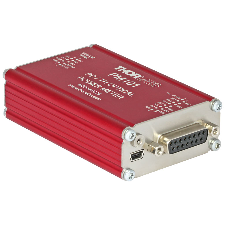
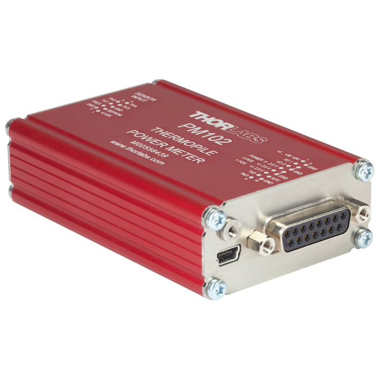
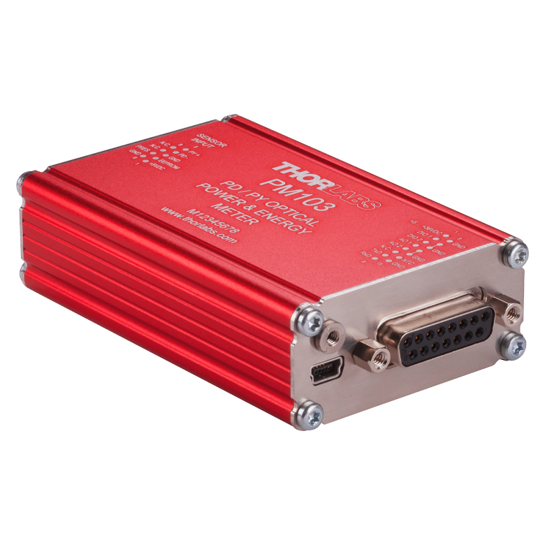
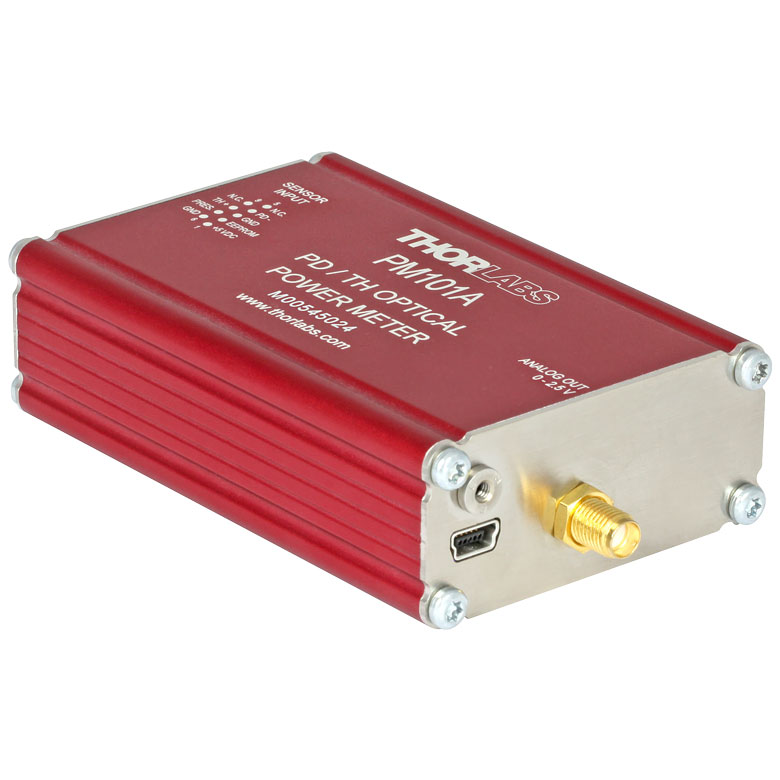

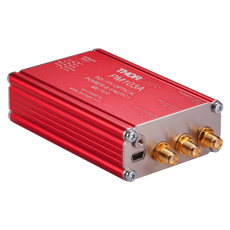
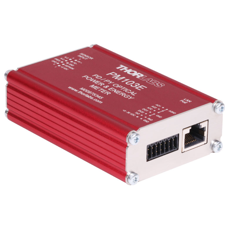
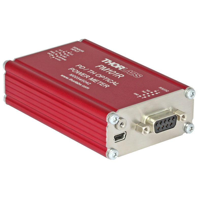
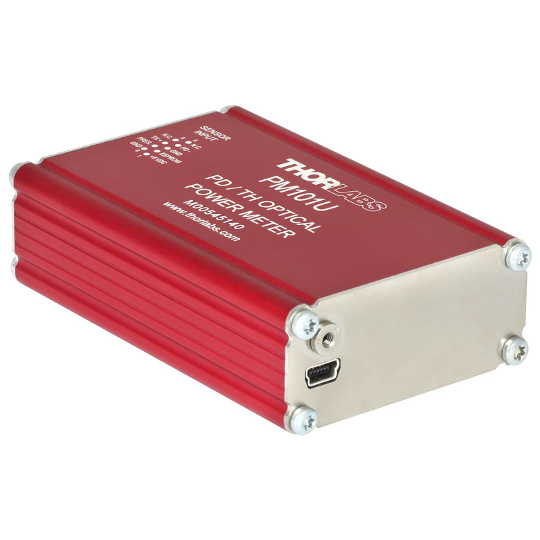
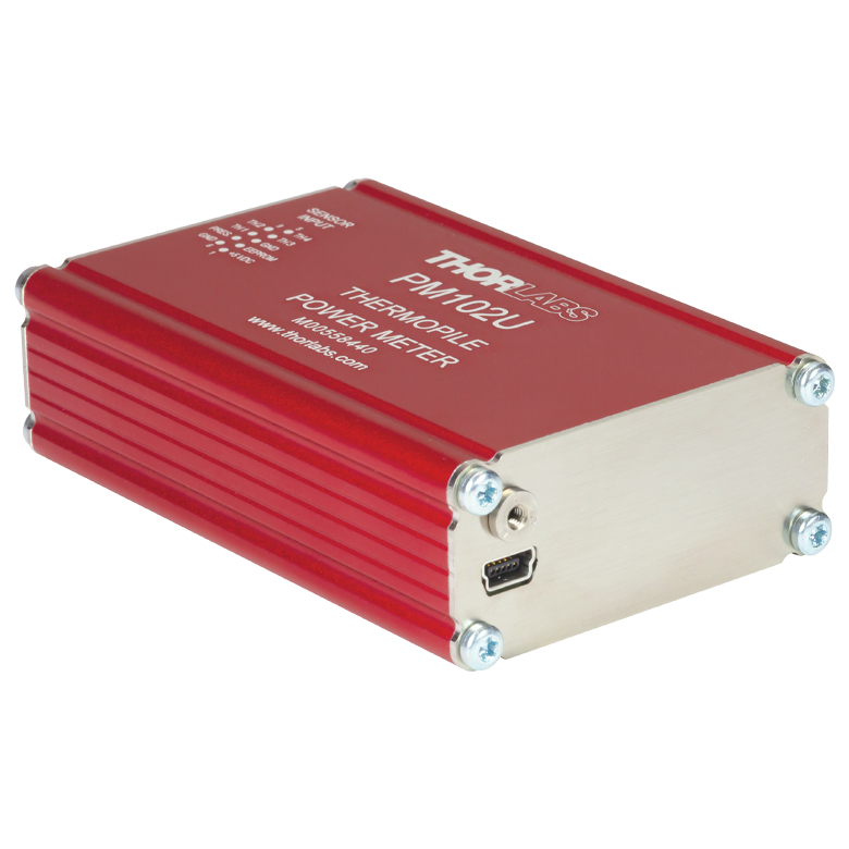
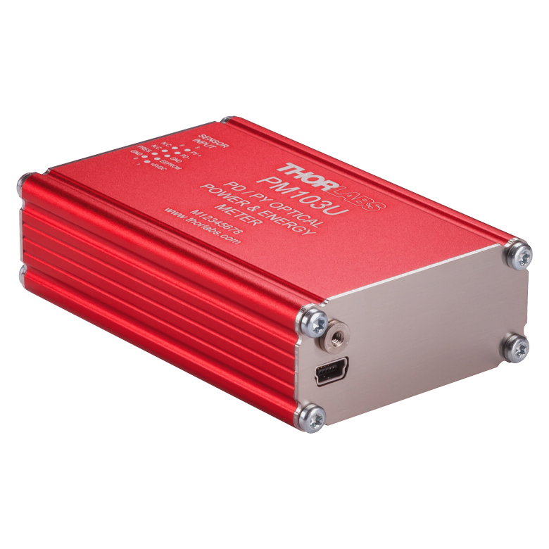


Figure 796A DAkkS-accredited calibrations are performed in accordance with DIN EN ISO/IEC 17025:2018.
Recalibration Services
Thorlabs offers two types of recalibration services in-house for our power and energy meter electronics and photodiode power sensors: ISO17025 accredited calibrations and manufacturer calibrations. Only the manufacturer calibration is available for the NS170C microscope slide peak power sensor, our thermal power sensors, and our pyroelectric energy sensors. All new products are delivered with a manufacturer calibration by default; if an ISO17025 accredited calibration is desired for a new device, please contact Tech Sales.
ISO17025 accredited calibrations are performed in-house in accordance with DIN EN ISO/IEC 17025:2018. Thorlabs GmbH's calibration laboratory is accredited by the German Accreditation Body (DAkkS), the national accreditation authority of the Federal Republic of Germany. The scope of services is described here in English or German. Accredited calibrated power and/or energy meter electronics come with a dedicated certificate of calibration proving the specified accuracy and traceability of calibration data. This certification may be required in certain applications or industries, such as the medical market.
In contrast, our manufacturer calibrations are subject to the quality management requirements of ISO9001. The certificate of calibration lists the equipment used for the calibration procedure as well as the calibration data acquired. The manufacturer calibration of a power sensor includes recalibration of a single-channel console or interface at no additional cost. If you wish to calibrate one or more sensors with a dual-channel console, each sensor and console calibration service will need to be purchased individually.
Both types of calibration can be offered for third-party equipment or adjusted for special requirements upon request. Please reach out to Tech Sales for further details.
We recommend recalibrating your Thorlabs sensor and console as a pair; however, each may be recalibrated individually. To ensure accurate measurements, we recommend recalibrating annually. To order one or more sensor recalibrations with a dual-channel console, we offer two options: either 1) fill out the Returns Material Authorization (RMA) form with each console and sensor Item # to be recalibrated and specify either manufacturer calibration or ISO17025 accredited calibration in the "Further Details" field, or 2) separately add each recalibration service Item # offered below to your cart.

Click to Enlarge
Figure 113A ワイヤレスパワーメータPM160とiPad mini(付属していません)。PM160はApple社のモバイルデバイスを使ってリモート操作が可能です。
こちらでは当社のパワーセンサおよびエネルギーセンサのラインナップをご紹介しています。対応するパワーメーターコンソールとインターフェイスについてはTable 113Bをご覧ください。
下記のパワーセンサおよびエネルギーセンサのラインナップのほかに、当社ではフォトダイオードまたはサーマルセンサのどちらかを内蔵するオールインワン型のワイヤレス機能付きパワーメータや小型USBパワーメータ、およびコンソール、センサーヘッド、ポスト取付け用のアクセサリを含むパワーメーターキットもご用意しております。
当社では4種類のセンサをご用意しております:
- フォトダイオードセンサ: フォトダイオードセンサは感度が波長に依存するので、単色光源もしくは単色に近い光源のパワー測定用に設計されています。このセンサから出力される電流は、入射光パワーと波長によって決まります。この電流はトランスインピーダンスアンプにより、入力電流に比例した電圧を出力します。
- サーマルセンサ: サーモパイルセンサは、広い波長範囲で比較的平坦な応答特性を持つ材料から作られているので、LEDやSLDなどの広帯域光源のパワー測定に適しています。このセンサは、入射光パワーに比例した電圧を出力します。
- サーマル位置&パワーセンサ: これらのセンサでは4つのサーモパイルセンサが正方形の4象限に配置されています。ユニットは各象限からの出力電圧を比較してビームの位置を算出します。
- 焦電エネルギーセンサ: 焦電センサは焦電効果を通じて出力電圧を発生しパルス光源の測定に適しています(ディテクタの時定数によって繰返し周波数は制限されます)。このセンサは、入力パルスエネルギに比例したピーク電圧を出力します。
| Table 113B Console Compatibility | ||||||||
|---|---|---|---|---|---|---|---|---|
| Console Item # | PM100A | PM100D | PM400 | PM5020 | PM101 Series | PM102 Series | PM103 Series | PM100USB |
| Photodiode Power |  | | | | | - | | |
| Thermal Power | | | | | | | - | |
| Thermal Position | - | - | | | - | | - | - |
| Pyroelectric Energy | - | a | a | | - | - | | a |
パワー&エネルギーセンサのセレクションガイド
当社のパワー&エネルギーセンサの仕様を比較する際には、2種類の選択をします。Table 113C、113D、113E、113Fでは、当社のセンサを種類別に分類して(フォトダイオード、サーマル、焦電)、主な仕様を記載しています。
またFigure 113Gと113Hでは、当社のフォトダイオードならびにサーマルパワーセンサの全ラインナップを波長範囲(Figure 113G)そしてパワー範囲 (Figure 113H)で比較できるようになっています。枠内には型番とセンサの仕様の範囲が記載されています。グラフにより、特定の波長範囲またはパワー範囲に適したセンサーヘッドが特定しやすくなっております。
| Table 113C Photodiode Power Sensors |
|---|


| Table 113D Thermal Power Sensors |
|---|


| Table 113E Thermal Position & Power Sensors |
|---|

| Table 113F Pyroelectric Energy Sensors |
|---|


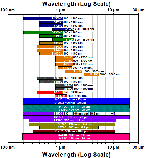 Figure 113G センサのラインナップ(波長範囲)
 Figure 113H センサのラインナップ(パワー範囲)
| Posted Comments: | |
Bryn Parry
(posted 2024-02-23 17:21:34.487) Please provide a metric option for this (or just default to metric parts if shipping to europe), I ordered it without realising that the post, post holder and base supplied with it are imperial ones! hchow
(posted 2024-02-26 06:52:34.0) Dear Mr. Parry, thank you for your feedback. My apologies. I am sorry to hear that you received the wrong items. I will personally reach out to you to rectify this mistake. Shengli Pu
(posted 2023-03-12 06:01:58.203) 我们曾经购买的“PM203”出现故障,还可以维修吗? jgreschler
(posted 2023-03-15 03:28:18.0) Thank you for reaching out to Thorlabs. The PM203 was obsoleted in 2019 and as such our ongoing repair service is limited but not terminated. I've reached out to you directly to discuss whether the repair you have falls into our capability. 80kmh
(posted 2017-09-11 18:35:39.067) Dear sir/madam,
I want to use this powermeter module.
Regarding the software, is it providing the software developing file for example SDK or library and etc...
I need it to develop my software using this item. swick
(posted 2017-09-12 03:56:58.0) This is a response from Sebastian at Thorlabs. Thank you for the inquiry. Our Power Meter Consoles can be controlled with SCPI commands. After installing the software package you can find examples e.g. in C# at path:
C:\Program Files (x86)\IVI Foundation\VISA\WinNT\PM100D\Example
I will contact you directly to provide further information about the driver. anatole.heliot
(posted 2016-04-26 04:45:15.563) Hello,
I'm using the PM120D pack (with S120C photodiode) for measuring an light intensity in function of time. I'm wondering if I can have a response time on the order of microsecond with the analog output.
Thank you,
Anatole HELIOT shallwig
(posted 2016-04-27 10:41:24.0) This is a response from Stefan at Thorlabs. Thank you very much for your inquiry. The analog output Bandwidth is DC-100 kHz dependent on the sensor. For the photodiodes sensors you can find the output bandwidth dependent on the current range in the manual on page 68 https://www.thorlabs.com/thorcat/17600/PM100D-Manual.pdf . I will contact you directly to check your application in more detail. jvigroux
(posted 2012-05-16 07:51:00.0) A resposne from Julien at Thorlabs: Dear Ken, thank you for your feedback! We indeed do not write explicitly that a post holder and a base are included in those bundles. We will modify the text on the webpage to make the exact component list clearer. ken
(posted 2012-05-16 08:23:07.0) They come with a post/holder/base? We do not see the information in the page here though. Ken jvigroux
(posted 2011-11-17 13:52:00.0) A response from Julien at Thorlabs: Dear Martin, I am really sorry about this inconvenience. We will ship you a replacement immediately. Concerning your question about the quality control, we do check each power meter individually before shipment. I unfortunately do not know what the exact problem with your console is but I assume something must have happened during the shipment. We will inspect the unit as soon as we have it back and take the appropriate measures to prevent such issue from happening again. I will contact you directly to sort out the shipping details for the replacement. m.j.slaman
(posted 2011-11-17 12:24:11.0) I have unpacked my PM204 (consists of a PM200 and a S120VC) but it is not reading anything. The measured value remains inf as well as the minimum and maximum value. Also in the applied software I don`t see any reading (value remains 0 or ---). I have auto ranging on an tried with several light conditions. In the software an indicator shows A (waiting for new measurement value)(in the left top corner) while I expect sometimes a T of "trigger". The detector itself is ok since it is functioning on a PM100D console. I have attached also a second detector (S155C)on the PM200 without success. I have checked for firmwareupdates but there are non available on the website. I can not find any reset functions or trigger-arm functions in the manual nor in the software. Did anybody check the console before chipping? That must be since a callibration sheet was shipped with it?!?!
How do I fix it?
Martin bdada
(posted 2011-10-10 17:12:00.0) Response from Buki at Thorlabs:
Thank you for using our Feedback tool. Our sensors measure light from 200nm upwards. We will contact you regarding the possibility of a custom sensor that can measure 193nm. matt.hansen
(posted 2011-10-10 13:43:09.0) To Whom:
What would bea good detector to use with our PM310D meter to measure 193 nm light in the nW range ?
Matt Hansen bdada
(posted 2011-10-06 20:36:00.0) Response from Buki at Thorlabs:
Thank you for your feedback. The PM120A has been replaced with the PM120D, which is designed for 400 - 1100nm and power levels of 50nW to 50mW. We will contact you to discuss your application. ryanlee
(posted 2011-10-06 17:58:46.0) Hi
Can you advise if the PM120A is suitable to check the below mentioned items?
1) 3M Curing Light 2500
http://dentista.pinoydental.com/component/page,shop.product_details/flypage,shop.flypage/product_id,20/category_id,9/manufacturer_id,0/option,com_virtuemart/Itemid,70/vmcchk,1/
2) Dymax Bluewave 75
http://www.dymax.com/products/curing_equipment/uv_spot_lamps/bluewave_75.php
Thanks!
Regards
Ryan jjurado
(posted 2011-05-04 13:27:00.0) Response from Javier at Thorlabs to dBolles: Thank you very much for contacting us. Yes, all of our C series sensors have NIST-traceable calibration data, as well as sensor information, saved in the DB9 connector. This information is automatically retrieved by our power meters as soon as the sensor is connected. dBolles
(posted 2011-05-04 08:41:42.0) Do all of your C detectors have the calibration data for the detector stored in the DB connector? fcao
(posted 2011-01-26 17:59:05.0) Hi Simon. Our China office will contact you shortly. simonhedwin
(posted 2011-01-26 15:05:21.0) ??PM121D?????? |
| Kit Item # | PM120VA |
|---|---|
| Click Image to Enlarge | 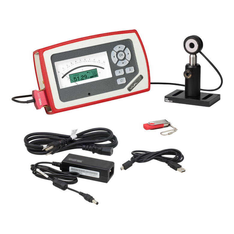 |
| Included Console Item # | PM100A |
| Display | Analog Needle with 132 x 32 Pixel LCD |
| Connectivity | USB 2.0 Connectivity |
| Console Sensor Compatibility | All C-Series Photodiode and Thermal Power Sensors |
| Post Assembly Threading | Imperial |
| Mounting Base Compatibility | Imperial |
| Included Sensor | S120VC |
|---|---|
| Wavelength Range | 200 - 1100 nm |
| Power Range | 50 nW - 50 mW (200 - 450 nm) 50 nW - 20 mW (450 - 1100 nm) |
| Resolution | 1 nW |
| Detector Type | Si Photodiode |
| Aperture | Ø9.5 mm |
| Spec Sheet |
こちらのキットにはメーターコンソールPM100A、フォトダイオードパワーセンサS120VC、ならびにベースBA2、ポストホルダPH2、Ø1/2インチポストTR2で構成されたポストアセンブリが含まれます。こちらのキットは可視域から近赤外域の低パワー(50 nW~50 mW)レーザ用の汎用キットです。センサの検出部は200~525 nmの光を吸収するアライメント用蛍光ディスクで囲まれています。このパワーメーターキットは、当社の多くの半導体レーザやHeNeレーザの計測に適しています。
当社ではパワー&エネルギーメーターキットの再校正サービスを提供しています。再校正の際はセット内のコンソールもご一緒にお送りください。
コンソールのみの再校正も承ります。再校正サービスの詳細につきましては、当社までお問い合わせください。
| Kit Item # | PM120D | PM400K1 |
|---|---|---|
| Click Image to Enlarge | 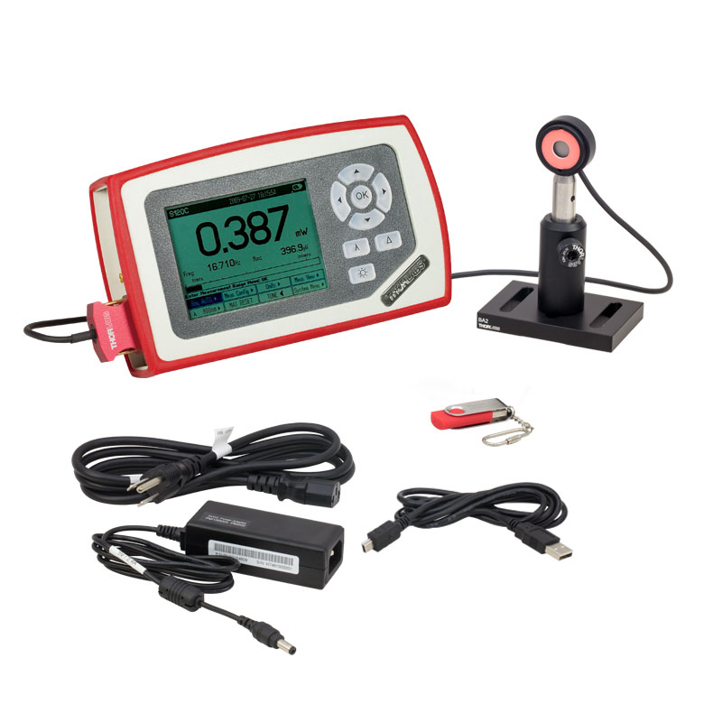 | 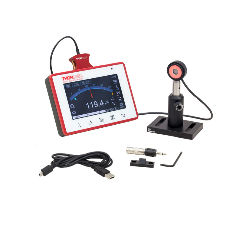 |
| Included Console Item # | PM100D | PM400 |
| Display | 4" Backlit Digital Display, 320 x 240 Pixel Resolution | 4.3" Capacitive Color Touchscreen, WQVGA Resolution |
| Connectivity | USB 2.0 Connectivity | |
| Console Sensor Compatibility | All C-Series Photodiode and Thermal Power Sensors as Well as All Pyroelectric Energy Sensors | |
| Post Assembly Threading | Imperial | |
| Mounting Base Compatibility | Imperial | |
| Included Sensor | S120C |
|---|---|
| Wavelength Range | 400 - 1100 nm |
| Power Range | 50 nW - 50 mW |
| Resolution | 1 nW |
| Detector Type | Si Photodiode |
| Aperture | Ø9.5 mm |
| Spec Sheet |
各キットにはパワーメーターコンソールPM100DまたはPM400、フォトダイオードセンサS120C、ならびにベースBA2、ポストホルダPH2、Ø1/2インチポストTR2で構成されたポストアセンブリが含まれます。こちらのキットは可視域から近赤外域の低パワー(50 nW~50 mW)レーザ用の汎用キットです。センサの検出部は400~640 nmおよび800~1700 nmの光を吸収するアライメント用蛍光ディスクで囲まれています。このパワーメーターキットは、当社の多くの半導体レーザやHeNeレーザの計測に適しています。
当社ではパワー&エネルギーメーターキットの再校正サービスを提供しています。再校正の際はセット内のコンソールもご一緒にお送りください。
コンソールのみの再校正も承ります。再校正サービスの詳細につきましては、当社までお問い合わせください。
| Kit Item # | PM121D | PM400K2 |
|---|---|---|
| Click Image to Enlarge | 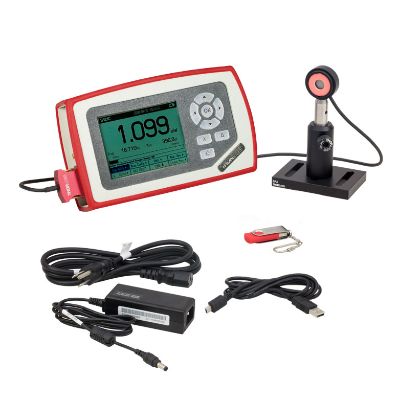 |  |
| Included Console Item # | PM100D | PM400 |
| Display | 4" Backlit Digital Display, 320 x 240 Pixel Resolution | 4.3" Capacitive Color Touchscreen, WQVGA Resolution |
| Connectivity | USB 2.0 Connectivity | |
| Console Sensor Compatibility | All C-Series Photodiode and Thermal Power Sensors as Well as All Pyroelectric Energy Sensors | |
| Post Assembly Threading | Imperial | |
| Mounting Base Compatibility | Imperial | |
| Included Sensor | S121C |
|---|---|
| Wavelength Range | 400 - 1100 nm |
| Power Range | 500 nW - 500 mW |
| Resolution | 10 nW |
| Detector Type | Si Photodiode |
| Aperture | Ø9.5 mm |
| Spec Sheet |
各キットにはパワーメーターコンソールPM100DまたはPM400、フォトダイオードセンサS121C、ならびにベースBA2、ポストホルダPH2、Ø1/2インチポストTR2で構成されたポストアセンブリが含まれます。こちらのキットは可視域から近赤外域(<1100 nm)の低~中程度のパワー(500 nW~500 mW)レーザ用の汎用キットです。上記のキットに含まれるS120Cに似ていますが、NDフィルタがセンサの手前で光を減衰します。センサの検出部は400~640 nmおよび800~1700 nmの光を吸収するアライメント用蛍光ディスクで囲まれています。
当社ではパワー&エネルギーメーターキットの再校正サービスを提供しています。再校正の際はセット内のコンソールもご一緒にお送りください。
コンソールのみの再校正も承ります。再校正サービスの詳細につきましては、当社までお問い合わせください。
| Kit Item # | PM130D | PM400K3 |
|---|---|---|
| Click Image to Enlarge | 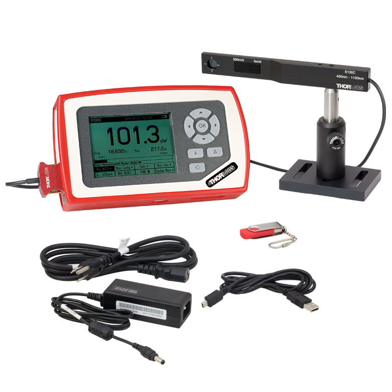 | 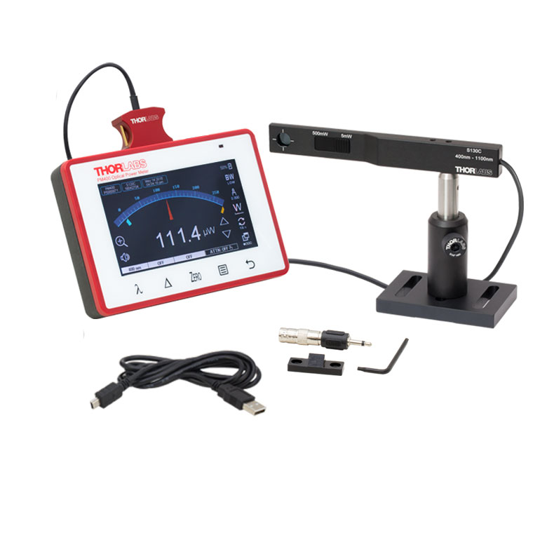 |
| Included Console Item # | PM100D | PM400 |
| Display | 4" Backlit Digital Display, 320 x 240 Pixel Resolution | 4.3" Capacitive Color Touchscreen, WQVGA Resolution |
| Connectivity | USB 2.0 Connectivity | |
| Console Sensor Compatibility | All C-Series Photodiode and Thermal Power Sensors as Well as All Pyroelectric Energy Sensors | |
| Post Assembly Threading | Imperial | |
| Mounting Base Compatibility | Imperial | |
| Included Sensor | S130C |
|---|---|
| Wavelength Range | 400 - 1100 nm |
| Power Range | 500 pW - 5 mW (Up to 500 mW with Filter)a |
| Resolution | 100 pW |
| Detector Type | Si Photodiode |
| Aperture | Ø9.5 mm |
| Spec Sheet |
各キットにはパワーメーターコンソールPM100DまたはPM400、フォトダイオードパワーセンサS130C、ベースBA2、ポストホルダPH2とØ1/2インチポストTR2で構成されたポストアセンブリが含まれます。このキットの薄型センサーヘッドは厚さが5 mmしかないので、狭いスペースでのご使用に適しています。 スライド式のNDフィルタは、センサを使って測定できるパワー範囲まで拡がっています。 フィルタが光路から出ると、500 pW~5 mWのパワーを測定することができます。 フィルタが光路に入ると、50 nW~500 mWのパワー測定が可能になります。ただし、パワーレベルが5 mW以下の場合、適切な結果を得るために光路内のフィルタ無しで測定する必要があります。 フィルタの位置は、パワーメーターコンソールによって、自動的に検出され表示されます。
当社ではパワー&エネルギーメーターキットの再校正サービスを提供しています。再校正の際はセット内のコンソールもご一緒にお送りください。
コンソールのみの再校正も承ります。再校正サービスの詳細につきましては、当社までお問い合わせください。
| Kit Item # | PM122D | PM400K4 |
|---|---|---|
| Click Image to Enlarge |  | 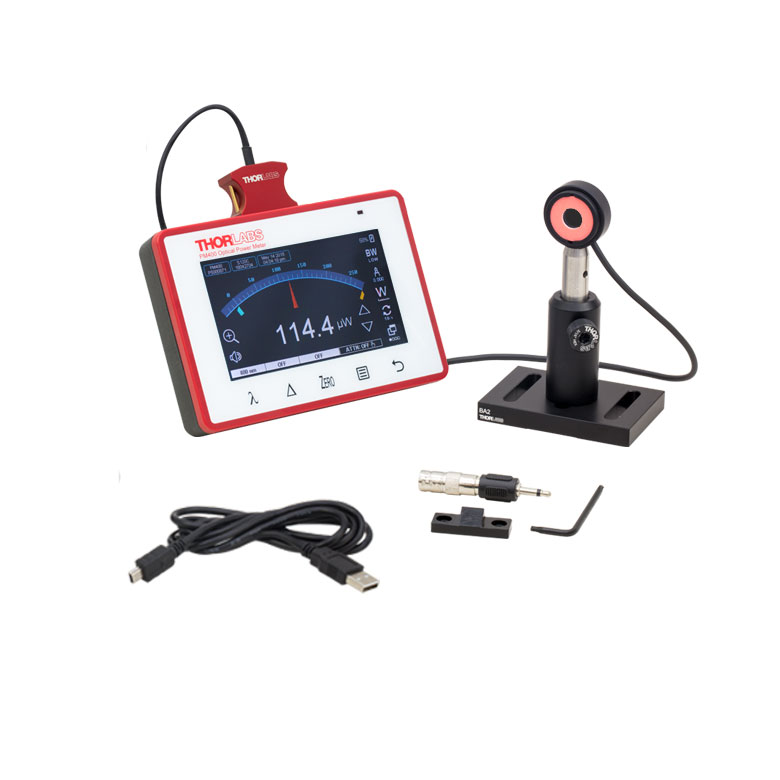 |
| Included Console Item # | PM100D | PM400 |
| Display | 4" Backlit Digital Display, 320 x 240 Pixel Resolution | 4.3" Capacitive Color Touchscreen, WQVGA Resolution |
| Connectivity | USB 2.0 Connectivity | |
| Console Sensor Compatibility | All C-Series Photodiode and Thermal Power Sensors as Well as All Pyroelectric Energy Sensors | |
| Post Assembly Threading | Imperial | |
| Mounting Base Compatibility | Imperial | |
| Included Sensor | S122C |
|---|---|
| Wavelength Range | 700 - 1800 nm |
| Power Range | 50 nW - 40 mW |
| Resolution | 2 nW |
| Detector Type | Ge Photodiode |
| Aperture | Ø9.5 mm |
| Spec Sheet |
各キットにはパワーメーターコンソールPM100DまたはPM400、フォトダイオードセンサS122C、ならびにベースBA2、ポストホルダPH2、Ø1/2インチポストTR2で構成されたポストアセンブリが含まれます。この組み合わせは、遠赤外域から近赤外域(700~1800 nm)の波長での使用に適しています。センサの検出部は400~640 nmおよび 800~1700 nmの光を吸収するアライメント用蛍光ディスクで囲まれています。
当社ではパワー&エネルギーメーターキットの再校正サービスを提供しています。再校正の際はセット内のコンソールもご一緒にお送りください。
コンソールのみの再校正も承ります。再校正サービスの詳細につきましては、当社までお問い合わせください。
| Kit Item # | PM125D | PM400K5 |
|---|---|---|
| Click Image to Enlarge |  | 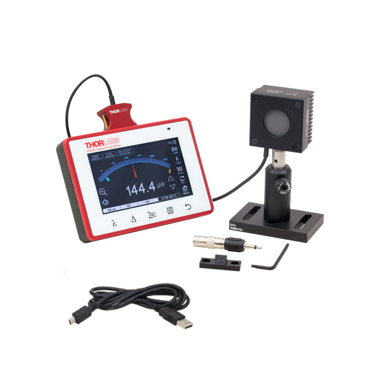 |
| Included Console Item # | PM100D | PM400 |
| Display | 4" Backlit Digital Display, 320 x 240 Pixel Resolution | 4.3" Capacitive Color Touchscreen, WQVGA Resolution |
| Connectivity | USB 2.0 Connectivity | |
| Console Sensor Compatibility | All C-Series Photodiode and Thermal Power Sensors as Well as All Pyroelectric Energy Sensors | |
| Post Assembly Threading | Imperial | |
| Mounting Base Compatibility | Imperial | |
| Included Sensor | S425C |
|---|---|
| Wavelength Range | 0.19 - 20 µm |
| Power Range | 2 mW - 10 W |
| Resolution | 100 µW |
| Detector Type | Thermal |
| Aperture | Ø25.4 mm |
| Spec Sheet |
各キットにはパワーメーターコンソールPM100DまたはPM400、フォトダイオードセンサS425C、ならびにベースBA2、ポストホルダPH2、Ø1/2インチポストTR2で構成されたポストアセンブリが含まれます。この組み合わせは、こちらは高パワー(最大10 W)のレーザや長い波長(最長20 µm)での使用に適した汎用キットです。 サーマルセンサS425Cは、0.6 sの優れた高速応答時間となっています。
当社ではパワー&エネルギーメーターキットの再校正サービスを提供しています。再校正の際はセット内のコンソールもご一緒にお送りください。
コンソールのみの再校正も承ります。再校正サービスの詳細につきましては、当社までお問い合わせください。
※パワーセンサ校正について - 当社のパワーセンサ校正は自動で行われており、測定と同時にセンサ内のメモリにある補正データを書き換えます(出力されるデータは校正前の感度と校正後の感度になります)。また、センサ面(NDフィルタ)が汚れ等で正常に感度測定ができないと判断された場合には、フィルタ交換(無償)してから校正される場合がございますので、ご了承ください。この場合は校正前の感度は測定できません。
| Table 236A Compatibility | |
|---|---|
| Calibration Service Item # | Compatible Sensors |
| CAL-UVPD | S120VC |
| CAL-PD | S116C, S120C, S121C, S170C, S140C, S142C, S142CL, S150C, S151C, PM16-120, PM16 |
| CAL-UVPD2 | S130VC |
| CAL-PD2 | S130C, PM16-130, PM160 |
| CAL-NS | NS170C |
| CAL-IRPD | S122C, S144C, S145C, S145CL, S146C, S154C, S155C, PM16-122, PM16-144 |
| CAL-IRPD2 | S132C |
| CAL-MIRPD | S148C, S180C |
Thorlabs offers recalibration services for our photodiode optical power sensors. To ensure accurate measurements, we recommend recalibrating the sensors annually. Recalibration of a single-channel power and/or energy meter console or interface is included with the recalibration of a sensor at no additional cost. If you wish to calibrate one or more sensors with a dual-channel console, each sensor and console calibration service will need to be purchased individually. For more details on these recalibration services, please click the Documents (![]() ) icons below.
) icons below.
Refer to Table 236A for the appropriate calibration service Item # that corresponds to your power sensor.
Requesting a Calibration
Thorlabs provides two options for requesting a calibration:
- Complete the Returns Material Authorization (RMA) form. When completing the RMA form, please enter your name, contact information, the Part #, and the Serial # of each item being returned for calibration; in the Reason for Return field, select "I would like an item to be calibrated." All other fields are optional. Once the form has been submitted, a member of our RMA team will reach out to provide an RMA Number, return instructions, and to verify billing and payment information.
- Select the appropriate sensor calibration Item # below, enter the Part # and Serial # of the sensor that requires recalibration, and then Add to Cart. If you would like a console calibrated with your sensor, repeat this process for Item # CAL-PM1 or CAL-PM2 below, entering the console Item # and Serial #. A member of our RMA team will reach out to coordinate the return of the item(s) for calibration. Note that each console calibration Item # represents the cost of calibrating a console alone; if requesting a single-channel console calibration with a sensor calibration, the appropriate discount will be applied when your request is processed. Should you have other items in your cart, note that the calibration request will be split off from your order for RMA processing.
Please Note: To ensure your item being returned for calibration is routed appropriately once it arrives at our facility, please do not ship it prior to being provided an RMA Number and return instructions by a member of our team.
| Table 791A Compatibility | |
|---|---|
| Calibration Service Item # | Compatible Sensors |
| CAL-UVPDD | S120VC |
| CAL-PDD | S116C, S120C, S121C, S170C, S140C, S142C, S142CL, S150C, S151C, PM16-120, PM16 |
| CAL-UVPD2D | S130VC |
| CAL-PD2D | S130C, PM16-130, PM160 |
| CAL-IRPDD | S122C, S144C, S145C, S145CL, S146C, S154C, S155C, PM16-122, PM16-144 |
| CAL-IRPD2D | S132C |
| CAL-MIRPDD | S148C |
Thorlabs offers ISO17025 accredited recalibration services for our photodiode optical power sensors. If you wish to calibrate one or more sensors with a console, each sensor and console calibration service will need to be purchased individually. ISO17025 accredited calibrations are performed in accordance with DIN EN ISO/IEC 17025:2018. Thorlabs GmbH's calibration laboratory is accredited by the German Accreditation Body (DAkkS), the national accreditation authority of the Federal Republic of Germany. The scope of services is described here in English or German. For more details on these recalibration services, please see the Recalibration tab or click the Documents (![]() ) icons below.
) icons below.
Refer to Table 791A for the appropriate calibration service Item # that corresponds to your power sensor.
Requesting a Calibration
Thorlabs provides two options for requesting a calibration:
- Complete the Returns Material Authorization (RMA) form. When completing the RMA form, please enter your name, contact information, the Part #, and the Serial # of each item being returned for calibration; in the Reason for Return field, select "I would like an item to be calibrated." In the Further Details field, please indicate "ISO17025 Accredited Calibration" or the desired calibration part number below in order to differentiate from the manufacturer calibration option. Once the form has been submitted, a member of our RMA team will reach out to provide an RMA Number, return instructions, and to verify billing and payment information.
- Select the appropriate sensor calibration Item # below, enter the Part # and Serial # of the sensor that requires recalibration, and then Add to Cart. If you would like a console calibrated with your sensor, repeat this process for Item # CAL-PM1, CAL-PM1D, CAL-PM2, or CAL-PM2D below, entering the console Item # and Serial #. A member of our RMA team will reach out to coordinate the return of the item(s) for calibration. Note that each console calibration Item # represents the cost of calibrating a console alone; if requesting a single-channel console calibration with a sensor calibration, the appropriate discount will be applied when your request is processed. Should you have other items in your cart, note that the calibration request will be split off from your order for RMA processing.
Please Note: To ensure your item being returned for calibration is routed appropriately once it arrives at our facility, please do not ship it prior to being provided an RMA Number and return instructions by a member of our team.
※パワーセンサ校正について - 当社のパワーセンサ校正は自動で行われており、測定と同時にセンサ内のメモリにある補正データを書き換えます(出力されるデータは校正前の感度と校正後の感度になります)。また、センサ面(NDフィルタ)が汚れ等で正常に感度測定ができないと判断された場合には、フィルタ交換(無償)してから校正される場合がございますので、ご了承ください。この場合は校正前の感度は測定できません。
| Table 317A Compatibility | |
|---|---|
| Sensor Type | Sensor Item #s |
| Thermal Power | S175C, S302Ca, S305Ca, S310Ca, S314Ca,S322C, S350C, S370C, S401C, S405C, S415C, S425C, S425C-L, S470C, PM160T, PM160T-HP, PM16-401, PM16-405 |
| Pyroelectric Energy | ES111C, ES120C, ES145C, ES220C, ES245C, ES308C, ES312C, ES408C, ES412C |
Thorlabs offers recalibration services for our Thermal Power and Pyroelectric Energy Sensors. To ensure accurate measurements, we recommend recalibrating the sensors annually. Recalibration of a single-channel power and/or energy meter console or interface is included with the recalibration of a sensor at no additional cost. If you wish to calibrate one or more sensors with a dual-channel console, each sensor and console calibration service will need to be purchased individually.
Please note that the CAL-THPY recalibration service cannot be used for our Thermal Position & Power Sensors; recalibration for these sensors can be requested by contacting Tech Support. Table 317A lists the sensors for which the CAL-THPY recalibration service is available.
Requesting a Calibration
Thorlabs provides two options for requesting a calibration:
- Complete the Returns Material Authorization (RMA) form. When completing the RMA form, please enter your name, contact information, the Part #s, and the Serial #s of all sensors or consoles being returned for calibration; in the Reason for Return field, select "I would like an item to be calibrated." All other fields are optional. Once the form has been submitted, a member of our RMA team will reach out to provide an RMA Number, return instructions, and to verify billing and payment information.
- Enter the Part # and Serial # of the item that requires recalibration below and then Add to Cart. If you would like a console calibrated with your sensor, repeat this process for Item # CAL-PM1 or CAL-PM2 below, entering the console Item # and Serial #. A member of our RMA team will reach out to coordinate the return of the item(s) for calibration. Note that each console calibration Item # represents the cost of calibrating a console alone; if requesting a single-channel console calibration with a sensor calibration, the appropriate discount will be applied when your request is processed. Should you have other items in your cart, note that the calibration request will be split off from your order for RMA processing.
Please Note: To ensure your item being returned for calibration is routed appropriately once it arrives at our facility, please do not ship it prior to being provided an RMA Number and return instructions by a member of our team. Pyroelectric energy sensors returned for recalibration or servicing must include the separate BNC to DB9 adapter, which contains the sensor EEPROM.
※パワーセンサ校正について - 当社のパワーセンサ校正は自動で行われており、測定と同時にセンサ内のメモリにある補正データを書き換えます(出力されるデータは校正前の感度と校正後の感度になります)。また、センサ面(NDフィルタ)が汚れ等で正常に感度測定ができないと判断された場合には、フィルタ交換(無償)してから校正される場合がございますので、ご了承ください。この場合は校正前の感度は測定できません。
| Table 719A Compatibility | |
|---|---|
| Calibration Service Item # | Compatible Consoles & Interfaces |
| Single-Channel | |
| CAL-PM1 | PM100D, PM100A, PM400, PM100USB, PM101 Series, PM102 Series, PM103 Series |
| Dual-Channel | |
| CAL-PM2 | PM5020, Previous-Generation PM320E |
These recalibration services are for the power and/or energy meter electronics of our consoles and interfaces. To ensure accurate measurements, we recommend recalibrating annually. Recalibration of a single-channel console or interface is included with these sensor recalibration services at no additional cost. If you wish to calibrate one or more sensors with a dual-channel console, each sensor and console calibration service will need to be purchased individually. For more details on these recalibration services, please click the Documents (![]() ) icons below.
) icons below.
Table 719A lists the power and/or energy meter consoles and interfaces that can be calibrated using the CAL-PM1 and CAL-PM2 recalibration services.
Requesting a Calibration
Thorlabs provides two options for requesting a calibration:
- Complete the Returns Material Authorization (RMA) form. When completing the RMA form, please enter your name, contact information, the Part #, and the Serial # of each item being returned for calibration; in the Reason for Return field, select "I would like an item to be calibrated." All other fields are optional. Once the form has been submitted, a member of our RMA team will reach out to provide an RMA Number, return instructions, and to verify billing and payment information.
- Select the appropriate Item # below, enter the Part # and Serial # of the item that requires recalibration, and then Add to Cart. If you would like to calibrate one or more sensors with your console, repeat this process for the appropriate sensor recalibration service above, entering the console Item # and Serial #. A member of our RMA team will reach out to coordinate return of the item(s) for calibration. Note that each console calibration Item # represents the cost of calibrating a console alone; if requesting a single-channel console calibration with a sensor calibration, the appropriate discount will be applied when your request is processed. Should you have other items in your cart, note that the calibration request will be split off from your order for RMA processing.
Please Note: To ensure your item being returned for calibration is routed appropriately once it arrives at our facility, please do not ship it prior to being provided an RMA Number and return instructions by a member of our team.
| Table 792A Compatibility | |
|---|---|
| Calibration Service Item # | Compatible Consoles & Interfaces |
| Single-Channel | |
| CAL-PM1D | PM100D, PM100A, PM400, PM100USB, PM101 Series, PM102 Series, PM103 Series |
| Dual-Channel | |
| CAL-PM2D | PM5020 |
These ISO17025 accredited recalibration services are for the power and/or energy meter electronics of our consoles and interfaces. If you wish to calibrate one or more sensors with a console, each sensor and console calibration service will need to be purchased individually. ISO17025 accredited calibrations are performed in accordance with DIN EN ISO/IEC 17025:2018. Thorlabs GmbH's calibration laboratory is accredited by the German Accreditation Body (DAkkS), the national accreditation authority of the Federal Republic of Germany. The scope of services is described here in English or German. For more details on these recalibration services, please see the Recalibration tab or click the Documents (![]() ) icons below.
) icons below.
Table 792A lists the power and/or energy meter consoles and interfaces that can be calibrated using the CAL-PM1D and CAL-PM2D recalibration services.
Requesting a Calibration
Thorlabs provides two options for requesting a calibration:
- Complete the Returns Material Authorization (RMA) form. When completing the RMA form, please enter your name, contact information, the Part #, and the Serial # of each item being returned for calibration; in the Reason for Return field, select "I would like an item to be calibrated." In the Further Details field, please indicate "ISO17025 Accredited Calibration" or the desired calibration part number below in order to differentiate from the manufacturer calibration option. Once the form has been submitted, a member of our RMA team will reach out to provide an RMA Number, return instructions, and to verify billing and payment information.
- Select the appropriate Item # below, enter the Part # and Serial # of the item that requires recalibration, and then Add to Cart. If you would like to calibrate one or more sensors with your console, repeat this process for the appropriate sensor recalibration service above, entering the console Item # and Serial #. A member of our RMA team will reach out to coordinate return of the item(s) for calibration. Note that each console calibration Item # represents the cost of calibrating a console alone; if requesting a single-channel console calibration with a sensor calibration, the appropriate discount will be applied when your request is processed. Should you have other items in your cart, note that the calibration request will be split off from your order for RMA processing.
Please Note: To ensure your item being returned for calibration is routed appropriately once it arrives at our facility, please do not ship it prior to being provided an RMA Number and return instructions by a member of our team.