 Products Home
直線移動ステージ(リニアステージ)、移動量12.7 mm
- 2.4" x 2.4" Stage with 1/4"-20 (M6) Mounting Holes
- Modular Design for Building 1-, 2-, or 3-Axis Stages
- Models with Adjuster Screws, Micrometers, or Differential Adjusters
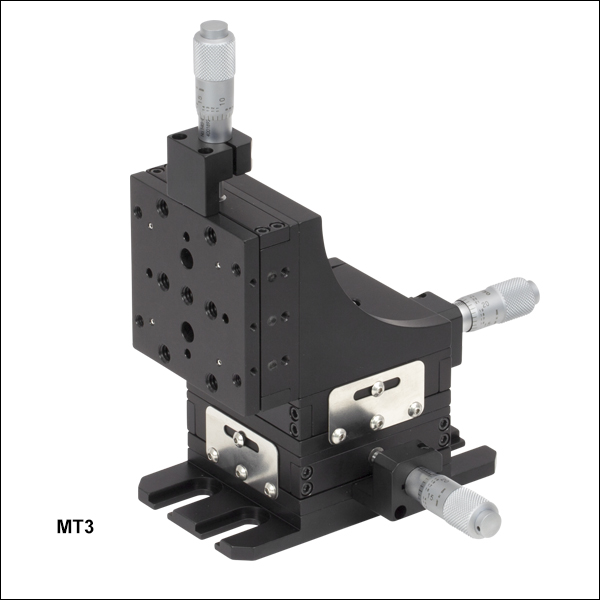
MT3
XYZ Stage with Standard Micrometers
MT1
Standard Micrometer
Application Idea
MT3 Stage Shown with an MT406 Top Plate, HFF001 Fiber Clamp, and HFS001 Strain Relief for Fiber Coupling Applications
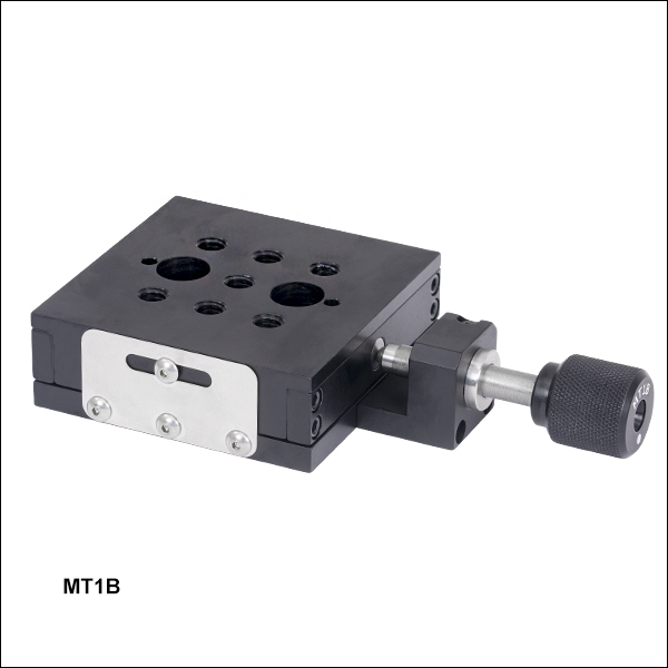
MT1B
1/4"-170 Adjuster Screw
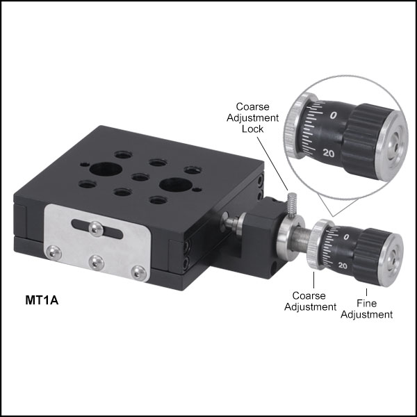
MT1A
Differential Adjuster


Please Wait

| Common Specifications | |
|---|---|
| Travel | 1/2" (12.7 mm) |
| Configuration | Left or Right Handed |
| XY Stacked Orthogonality | < 5 mrad |
| Angular Deviation | < 250 µrad |
| Bearing Type | Ball on Hardened V-Grooves |
| Ball Bearing-Mechanism Manual Translation Stages |
|---|
| 1/4" (6 mm) Travel |
| 1/2" (12.7 mm) Travel |
| 1/2" (13 mm) Travel, Miniature |
| 1" (25 mm) Travel |
| 2" (50 mm) Travel |
Click to Enlarge
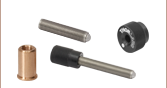
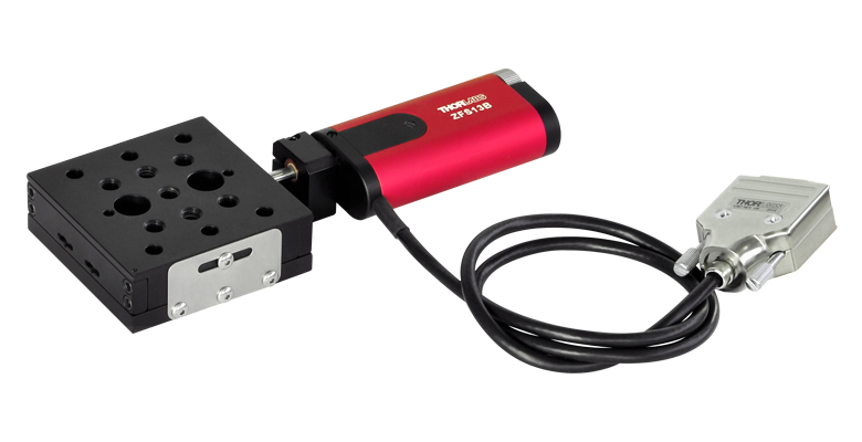
MT1(/M)、MT1B(/M)、MT1A(/M)のアジャスタの代わりに
モーターアクチュエータZFS13Bなどあらゆる
Ø3/8インチ(Ø9.5 mm)バレル型アクチュエータが取り付け可能です。
特長
- モジュール設計によりXYまたはXYZステージを構築可能
- 手動もしくは電動アクチュエータ付きのモデルをご用意
- すべてのØ3/8インチ(Ø9.5 mm)バレル型アクチュエータに対応
- M6ならびにM4取付け穴
- 側面にロックネジ
MTシリーズの直線移動ステージ(リニアステージ)の移動量は12.7 mmで、長寿命で精密な動きが可能な硬化スチール製リニアベアリングを採用しています。ステージは所望の位置に移動後、側面にある1.5 mm六角穴付きロック用ネジで位置固定することができます。MT1/M、MT1B/M、MT1A/Mは、組み合わせて2軸または3軸のプラットフォームに構築できます。詳細は「XYZアセンブリ」のタブをご覧ください。
こちらの移動ステージは、1/4”-170アジャスタ付き(型番:MT1B/M)、標準マイクロメータ付き(MT1/M)、差動アジャスタDM10付き(MT1A/M)のモデルをご用意しています。MTシリーズの移動ステージのアクチュエータは、バレルクランプ上のネジを緩めることによって取り外しできます。アクチュエータを一度取り外してステージの側面に取り付ける方法については、「アクチュエータの取り外し」タブをご参照ください。
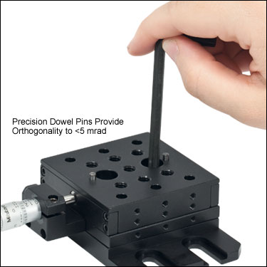
各ステージには2個の精密位置決めピンが付属しており、右手または左手配列のXYステージを5 mrad未満の優れた直交性で積み重ねます。組み立て済みのXYZ構成ステージ(右手配列)もご用意しております(下記型番MT3/MまたはMT3A/M参照)。
注: MTシリーズの移動ステージはマイクロメータ無しでもご購入いただけます。詳細については当社までお問い合わせください。代わりにØ3/8インチ(Ø9.5 mm)バレルの手動または電動アクチュエータを取り付けることができます。また、バレルアダプタをご用意している調整ネジもございますので、こちらを下記ステージにお使いいただくことも可能です。
MTシリーズ移動ステージのモジュール設計により、2軸または3軸のステージを数分程度で組み立てられます。ステージには2つの精密位置決めピンが付いているので、複数のステージを直交性を維持しながら右手および左手方向のXY構成に組み立てることができます。3軸のXYZ移動ステージ(MT3/M)の組み立ては下の手順で行ってください。
ステップ1
2つのM6キャップスクリュを使ってベースMT401/Mを移動ステージMT1/Mに取り付けます。
ステップ2
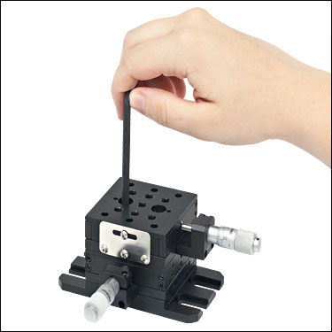
2台目の直交した移動ステージMT1/Mを、上のように2つのM6キャップスクリュを使って取り付けます。
ステップ3
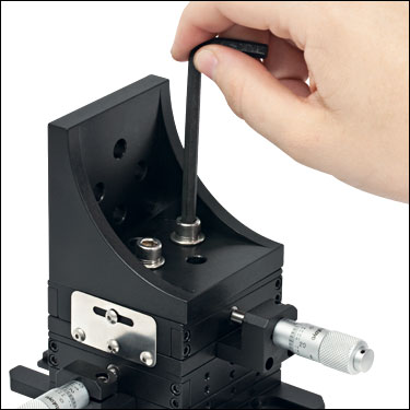
上図のように、2つのM6キャップスクリュを使って直角ブラケットMT402を移動ステージMT1/Mに取り付けます。
ステップ4
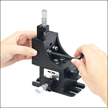
2つのM6キャップスクリュを使って、3台目の移動ステージMT1/Mを直角ブラケットMT402の後ろに取り付けます。
MTシリーズ移動ステージのアクチュエータの取り外し
当社のMTシリーズ移動ステージには取り外しが可能なアクチュエータが付いています。この特長により、例えば、側面取付けアクチュエーターアダプタMT405ならびに#3/32六角レンチを使用し、アクチュエータをロッキングプレートとは反対側のステージ側面に取り付けることができます。なお、ロッキングプレート側の側面はアダプタMT405を使用してアクチュエータを取り付けられませんのでご注意ください。下記はステージMT1の例ですが、アクチュエータの取り外しについてはMT1B/MならびにMT1A/Mも同様です。
MT1(/M)にはステージの前面に取り外し可能なマイクロメータが付いています。アダプタMT405ならびに#3/32六角レンチを使用することにより、マイクロメータを新たに2方向、合計3方向に取り付けることが可能です。当社ではアクチュエータを下記以外の方向に取り付けることはお勧めしておりません。ロッキングプレートを外して、アクチュエータをその側面に取り付けないようにご注意ください。
注:MTシリーズの移動ステージには幅広い種類のアクチュエータを取付けられますが、MT405を使って他のアクチュエータを側面に取付ける際には十分なクリアランスがあることを確認してください。MTシリーズステージのアクチュエータはMT405を使用して側面に取付け可能です。他のアクチュエータの適合性についてご質問等がございましたら、当社までお問い合わせください。
配置方向1

Click to Enlarge
配置方向1: ステージMT1(/M)の前面に取り付けられているマイクロメータ
配置方向2
Click to Enlarge
配置方向2: ステージのロッキングプレートとは反対側の側面に取り付けられているマイクロメータ
配置方向3

Click to Enlarge
配置方向3: ステージのロッキングプレートとは反対側の側面に取り付けられているマイクロメータ
Video Insight(How-To動画):MT直線移動ステージ(リニアステージ)に電動アクチュエータを取り付ける方法
この動画では、当社のMT直線移動ステージの手動アクチュエータを、リモート操作が可能となる電動アクチュエータに交換する方法のデモがご覧いただけます。交換する際には、電動アクチュエータの移動距離と取付バレルがMT直線移動ステージに適合しているかどうかご確認ください。電動アクチュエータの取付方法の詳細がこちらでご覧いただけます。
そのほかにも実験室でお使いいただけるヒント、工夫や方法などの動画がこちらからご覧いただけます。また、ウェビナーでは、当社製品を実用的かつ理論的にご紹介しています。
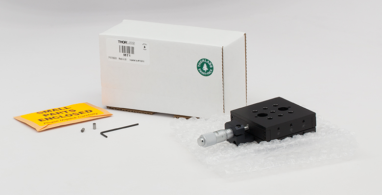
Click to Enlarge
Figure 5.1 MT1 Packaging

| Item # | % Weight Reduction |
CO2-Equivalent Reductiona |
|---|---|---|
| MT1 | 35.44% | 57.95 kg |
| MT1/M | 35.44% | 55.72 kg |
Smart Pack
- Reduce Weight of Packaging Materials
- Increase Usage of Recyclable Packing Materials
- Improve Packing Integrity
- Decrease Shipping Costs
Thorlabs' Smart Pack Initiative is aimed at waste minimization while still maintaining adequate protection for our products. By eliminating any unnecessary packaging, implementing packaging design changes, and utilizing eco-friendly packaging materials for our customers when possible, this initiative seeks to improve the environmental impact of our product packaging. Thorlabs' MT1(/M) Translation Stages with Standard Micrometer are now shipped in re-engineered packaging that minimizes the weight and the use of non-recyclable materials.b As we move through our product line, we will indicate re-engineered packages with our Smart Pack logo.
| Posted Comments: | |
Ryan Desaulniers
(posted 2024-02-12 10:37:38.087) Just wanted to let you know it looks like your part's PDF drawing doesn't look like it matches up with the STEP file or the actual part.
Dimension 1.50in between dowel pin holes appears to be 1.60in on the part I received and your step file.
Just figured I'd let you guys know.
-Ryan Desaulniers jdelia
(posted 2024-02-15 04:21:21.0) Thank you for contacting Thorlabs. The 1.50" called out in our CAD drawing only refers to the two pairs of dowel pin holes on the sides of the base of MT1. For the two dowel pin holes located on the mounting surface of the MT1, the distance is not called out in our CAD drawing, but it is in fact 1.60". Nazim Bharmal
(posted 2022-05-12 14:00:27.753) Is the maximum horizontal load incorrect? 90lbs seems unrealistic. jdelia
(posted 2022-05-26 10:55:56.0) Thank you for contacting Thorlabs and for pointing this out. The 90 lbs load spec is a typo and we will look into getting that fixed. The listed load capacity should actually be around 50 lbs. user
(posted 2022-03-22 09:07:39.36) Hello,
We use this stage at out company on a gluing setup, to hold the part to be glued in position. However, we noticed what appears to be the glue shrinkage affecting the position of the part while curing. At the moment, we are looking for something similar with a locking mechanism so that the part does not move during the curing process. Could you direct me to such a solution.
Thank you and best regards. jdelia
(posted 2022-03-23 09:13:33.0) Thank you for contacting Thorlabs. Fortunately, the MT1/M stage does in fact feature a side-located set screw to lock the platform in place. I have also reached out to you individually to discuss your application. youngsun jo
(posted 2021-10-20 19:42:49.713) Nice to meet you. I have a question about the spec content.
I'm not sure what you mean by horizontal and vertical loads. Is the micrometer's axis the reference? YLohia
(posted 2021-12-23 10:44:39.0) Thank you for contacting Thorlabs. The horizontal load capacity refers to the maximum load the stage can bare when the base of the stage is parallel to the optical table. Similarly, the vertical load capacity is the maximum load the stage can bare when the base of the stage is perpendicular to the optical table. user
(posted 2021-04-12 05:44:50.67) Hello, can you give information about the tolerances used, especially for the height of the MT1-M Stage and the Base Plate (MT401-M)? Thank you YLohia
(posted 2021-04-14 10:12:36.0) A true tolerance value would depend on the location of the moving world along the travel range, and require an extensive GD&T calculation. Based on the top and bottom plates’ height tolerances alone (and not taking into account the pre-loaded ball bearings that lie between the plates), a loose estimate is on the order of ±0.015” for the overall height tolerance. The MT401/M has a height tolerance of 0.400" ± 0.005" akuznetsov
(posted 2019-01-02 17:01:10.087) MT401 is missing min. breadboard mount screw distance call out in the PDF, please add min and maximum screw distance callout for securing to breadboard. llamb
(posted 2019-01-03 10:49:46.0) Thank you for pointing this out. The minimum breadboard mounting screw distance you're looking for is 2.94" for the MT401. Our team will update the PDF drawings. user
(posted 2018-07-19 11:04:50.51) Is the stage as shown in the pictures and CAD files in a central or extremal position with respect to specified 13 mm travel? I.e. is there room for it to travel 6.5 mm in both directions or can it only/predominantly in one, from the position in which it is shown (i.e. top holes on travelling sled aligned with counterbores of bottom part, so that M6 screw can be inserted for screwing onto breadboard, if I see correctly). llamb
(posted 2018-07-19 08:43:56.0) Thank you for contacting Thorlabs. The stages shown here are in their nominal, centered position. This means that from the position shown in the CAD file and drawings they can translate in either direction at ±6.5 mm. The clearance bores on the base of the stages can be accessed from this nominal position. kswitkowski
(posted 2018-03-22 06:55:55.117) Hi,
I am using MT3A/M since 2 years, and I noticed quite high slack's on all axes. Do you have any advice, how can I minimize it. I have already tightened all screws and It did not improve. llamb
(posted 2018-04-03 04:41:20.0) Hello, thank you for contacting Thorlabs. Quantifying the slack and load would be the first step for minimizing these effects. The bearing mechanism cannot easily be adjusted remotely, so we typically suggest these to be returned for on-site evaluation if performing poorly. I will reach out to you directly to troubleshoot further. tomerg
(posted 2015-12-02 11:24:07.25) Hi there.
1. The 1/2" and 2" manual translation stages have locking screws while that of the 1" does not have, right? what is the reason and can the 1" stage (pt1a/m for example) be configured with a locking screw?
2. If I want to order the mt1/m with differential adjuster (dm10), do I recieve the stage with the standard micrometer and the adjuster separately, or can I get the stage with no micrometer at a lower cost?
Thanks, Tomer. besembeson
(posted 2015-12-02 04:18:32.0) Response from Bweh at Thorlabs USA: It depends on the design and the choice of micrometer/actuators. The PT1A/M has a locking screw for the coarse adjustment. We can provide the MT1/M with the differential adjuster, DM10 already mounted as a special item. We can also provide the stage without the adjuster if you prefer that. I will followup with you regarding quoting these, and a special PT1A/M as required by your application. tesar
(posted 2013-08-27 12:15:19.03) Is the MT1/M translation stage available without a micrometer? jlow
(posted 2013-08-27 08:59:00.0) Response from Jeremy at Thorlabs: The translation stage is available without a micrometer. We will contact you directly for a quote. jlow
(posted 2013-01-04 08:36:00.0) Response from Jeremy at Thorlabs: Both the flatness and straightness for the stage should be =0.001". mayeul.duranddegevigney
(posted 2013-01-03 09:26:25.33) Hello,
Do you have information on the flatness and straightness of this stage?
Kind Regards user
(posted 2011-03-15 15:02:31.0) height of mt1 not shown in drawing Thorlabs
(posted 2010-10-12 18:48:57.0) Response from Javier at Thorlabs to piaa06: We can certainly offer the ball bearings separately. I will contact you directly to discuss the details. piaa06
(posted 2010-10-12 15:29:05.0) Hello,
Can I buy the ball bearings inside the MT1 stage separately?
I recently lost some of them. klee
(posted 2009-12-09 12:44:14.0) A response from Ken at Thorlabs to mheinric: Can you tell me what software you used to open them? I could open them in SolidWorks with no problem. mheinric
(posted 2009-12-09 09:31:25.0) Your AutoCAD dxf drawings for the MT1 & MT1/M are corrupt. jens
(posted 2009-06-15 15:45:18.0) A reply from Jens at Thorlabs: the MT stages offer a modular design which means that you can combine individual stages with manual actuator and DC motor, the part number for the manual version is MT1 for the motorized version MT1-Z8. In order to connect them you would need the base plate MT401 and the bracket MT402. We can set up a single part number for this and assemble it here for you. Since in that case the items will not just be shipped from stock it might add one or two days to the lead time, using that standard part numbers the items can ship same day. bilal
(posted 2009-06-15 12:29:50.0) Hello,
I need the MT3/M but I need the Z axis movement to be motorized. will you ba able to supply such positioner (complete)? how long will it take? how much will it cost me?
thanks
Best regards
Bilal Saudi
Pythagoras-Solar Ltd. Tyler
(posted 2008-12-09 10:33:06.0) A response from Tyler at Thorlabs to cohensr: The solid model drawing of the mt1/m stage was sent to you. Thank you for considering one of our translation stages. cohensr
(posted 2008-11-29 17:06:56.0) Dear Sir.
Pls send me solid model of mt1/m stage.
the model in your site build from surfaces and is not solid.
Thank You
Shlomo Tyler
(posted 2008-10-27 14:17:26.0) A response from Tyler at Thorlabs to ken.harte: The drawings for each translation stage are available on the "Drawings and Documents" tab located above. I will check to make sure that the files are properly linked. I will also email the file directly to you. Thank you for your interest in our products and if we can assist you in any other way, please ask. ken.harte
(posted 2008-10-23 13:43:48.0) I cant get a DXF drawing of this stage, which I need to integrate it into an optical system. |
手動リニアステージ
手動の移動ステージとして、最大移動量が6 mm以下から50 mmまでのステージをご用意しています。ステージの多くはXY軸やXYZ軸などの多軸構成での注文が可能です。ファイバ結合用としては、多軸ステージのページをご覧ください。標準の手動ステージを用いるよりも精密な調整が可能です。直線移動ステージのほかにも、回転ステージ、ピッチ&ヨープラットフォームおよびゴニオメータもご用意しております。また、DCサーボモータ、ステッピングモータ、またはダイレクトドライブ技術を用いた電動移動ステージもご用意しています。
クロスローラーベアリングステージ
こちらの直線移動ステージの移動機構には、精密移動、高耐荷重、小角度偏差といった特性を有するクロスローラーベアリングが用いられています。LNRシリーズステージの本体はスチール製、LX、XRNおよびXRシリーズステージの本体はアルミニウム製です。当社ではクロスローラーベアリングを用いた垂直移動ステージもご用意しております(下記参照)。
| Crossed-Roller Bearing Stages | ||||||
|---|---|---|---|---|---|---|
| Product Family | LNR Series 25 mm Stages | LX Series 25 mm Stages | XRN Series 25 mm Stages | XR Series 25 mm Stages | XR Series 50 mm Stages | LNR Series 50.8 mm Stages |
| Click Photo to Enlarge | 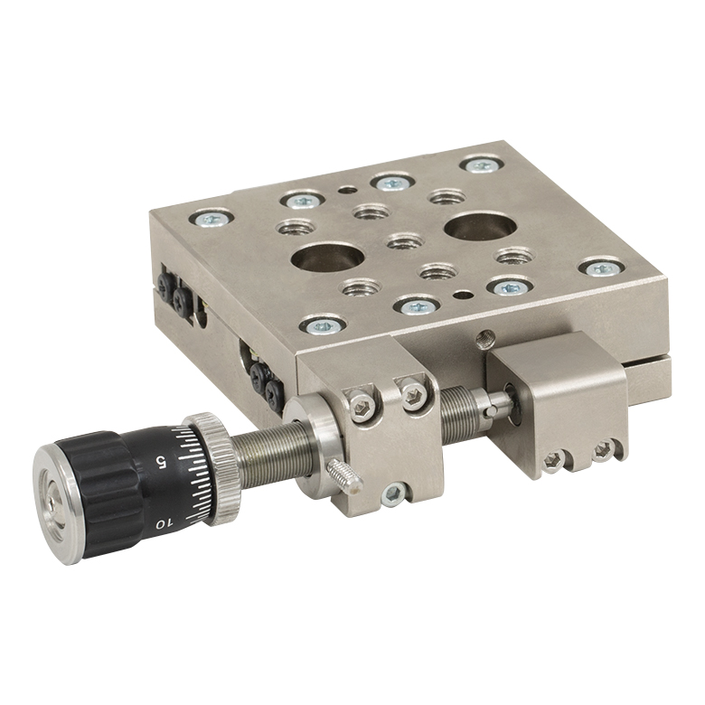 |  | 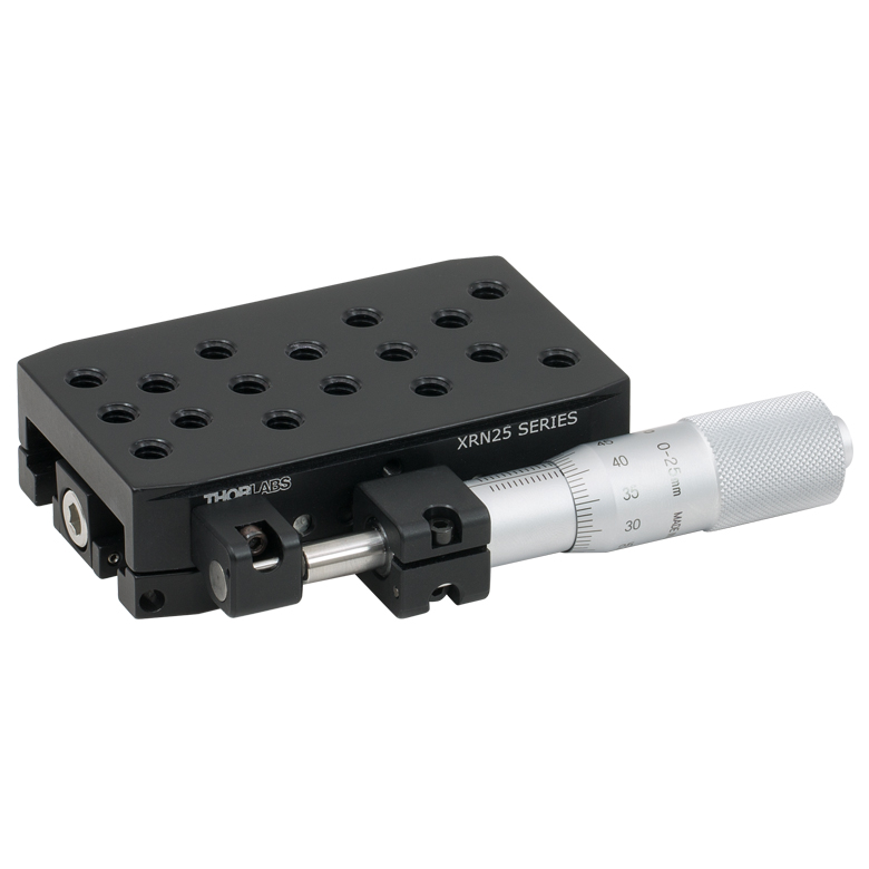 | 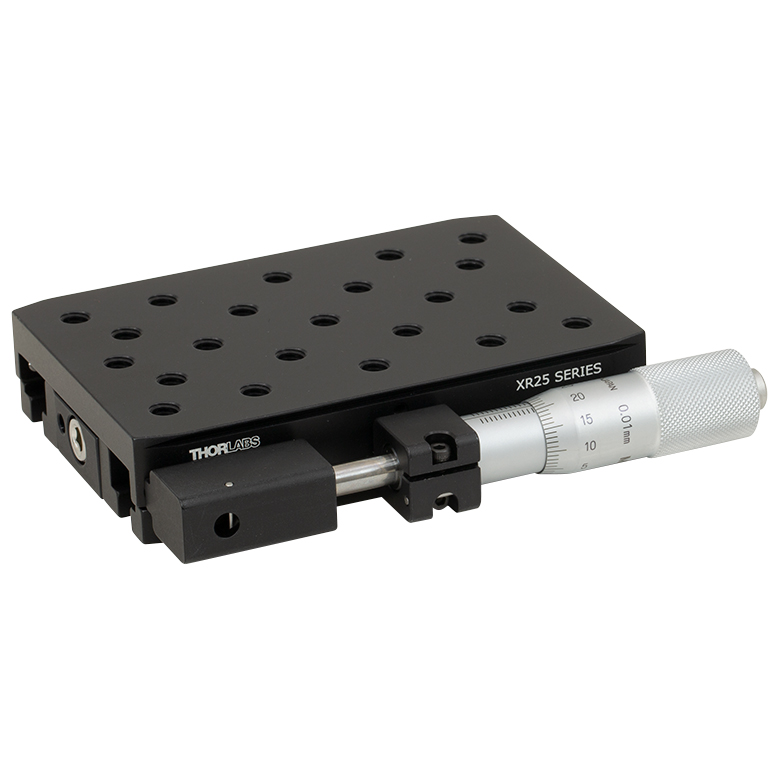 |  | 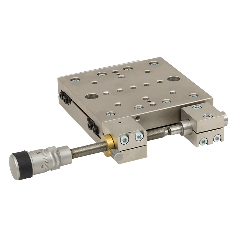 |
| Travel | 25 mm (0.98") | 25 mm (0.98") | 25 mm (0.98") | 25 mm (0.98") | 50 mm (1.97") | 50.8 mm (2") |
| Drive Type | Multiple | Micrometer | Micrometer | Micrometer | Micrometer | Multiple |
| Platform Size | 2.34" x 2.36" (59.4 mm x 60.0 mm) | 2.56" x 2.56" (65.0 mm x 65.0 mm) | 2.00" x 3.35" (50.7 mm x 85.0 mm) | 2.98" x 4.33" (75.7 mm x 110.0 mm) | 2.98" x 5.51" (75.7 mm x 140.0 mm) | 3.94" x 3.94" (100.0 mm x 100.0 mm) |
| Possible Axis Configurations | X, XZ, XY, XYZ | X, XY, XZ, YZ, XYZ | X, Y, Z, XY, XZ, YZ, XYZ | X, Y, Z, XY, XZ, YZ, XYZ | X, Y, Z, XY, XZ, YZ, XYZ | X, XY, XYZ |
| Additional Details | ||||||
ボールベアリングステージ
こちらの移動ステージでは、精密移動と長寿命を実現するために、硬化スチール製リニアベアリングが用いられています。様々なアクチュエータが付いた製品や、1軸ステージや予め多軸ステージとして構築された製品をご用意しております。
| Ball Bearing Stages | |||||
|---|---|---|---|---|---|
| Product Family | MS Series 1/4" Stages | T12 Series 1/2" Stages | MT Series 1/2" Stages | PT Series 1" Stages | LT Series 2" Stages |
| Click Photo to Enlarge |  | 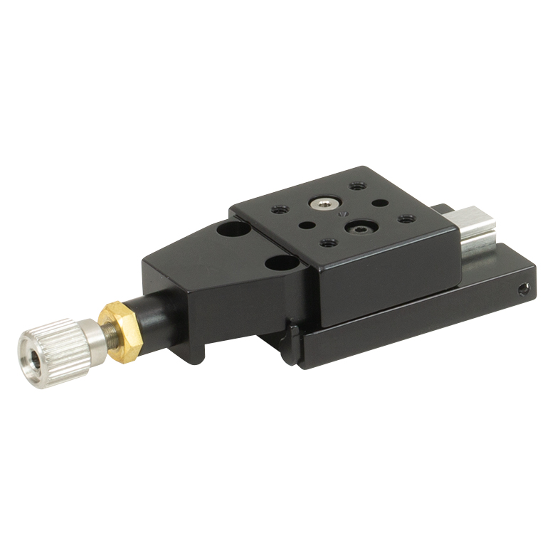 | 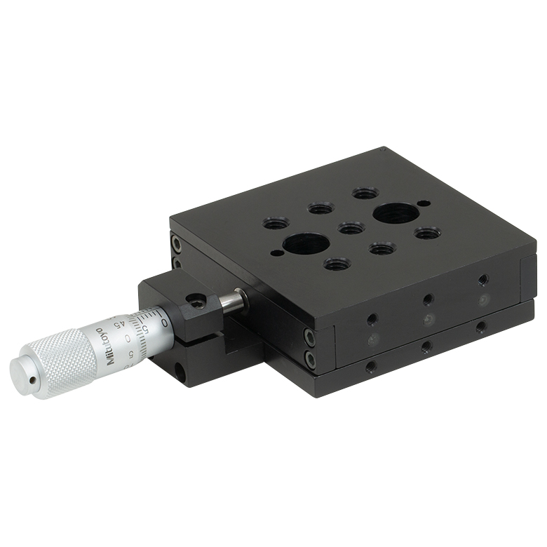 | 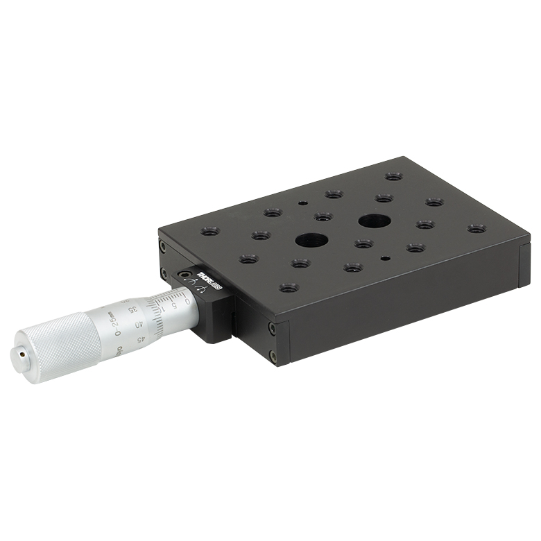 | 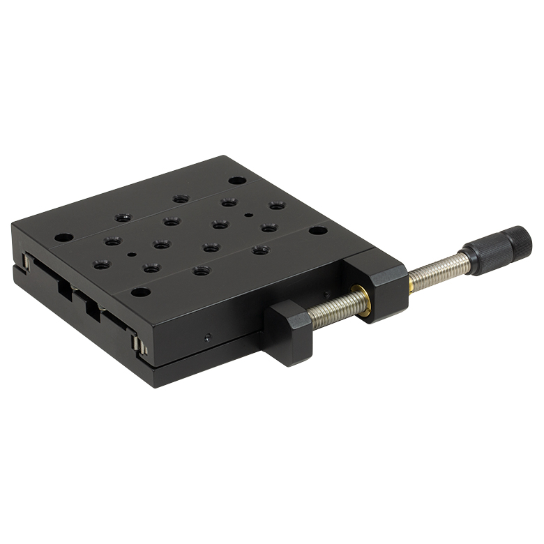 |
| Travel | 1/4" (6.4 mm) | 1/2" (12.7 mm) | 1/2" (12.7 mm) | 1" (25.4 mm) | 2" (50 mm) |
| Drive Type | Multiple | Thumbscrew | Multiple | Multiple | Differential Micrometer |
| Platform Size | 1.17" x 1.17" (29.7 mm x 29.7 mm) | 0.76" x 0.81" (19.3 mm x 20.6 mm) | 2.40" x 2.41" (61.0 mm x 61.2 mm) | 3.00" x 4.00" (76.2 mm x 101.6 mm) | 3.75" x 3.75" (95.3 mm x 95.3 mm) |
| Possible Axis Configurations | X, XY, XYZ | X, XY, XYZ | X, XY, XYZ | X, XY, XYZ | X, XY, XYZ |
| Additional Details | |||||
アリ溝式ステージ
これらの小型ステージの移動機構にはアリ溝と送りネジが組み込まれています。一般的な移動制御用に適したステージです。
| Dovetail Stages | |||
|---|---|---|---|
| Product Family | DT Series 1/2" Stages | DTS Series 1" Stages (Vacuum-Compatible Version Available) | DTS Series 2" Stage |
| Click Photo to Enlarge |  |  | 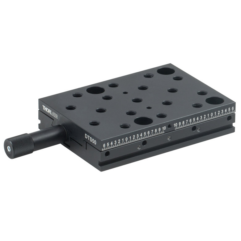 |
| Travel | 1/2" (12.7 mm) | 1" (25 mm) | 2" (50 mm) |
| Drive Type | Thumbscrew | Thumbscrew | Thumbscrew |
| Platform Size | 1.00" x 1.00" (25.4 mm x 25.4 mm) | 2.68" x 2.95" (68.0 mm 75.0 mm) | 2.68" x 3.74" (68.0 mm x 95.0 mm) |
| Possible Axis Configurations | X, XY, XYZ | X, XY, XYZa | X, XY, XYZ |
| Additional Details | |||
フレクシャーステージ
移動ステージNanoflex™には摩擦の無いフレクシャー機構が用いられており、ベアリングを用いた同様のステージと比較して位置決め性能と分解能が向上しています。ステージの移動は、取付けプラットフォームに取り付けられた連結部の弾性変形(たわみ)によって実現されています。多くのモデルには、微細な位置調整用にピエゾアクチュエータも付属します。
| Flexure Stages | ||||
|---|---|---|---|---|
| Product Family | Nanoflex™ 1.5 mm Stage | Nanoflex™ 5 mm Stages | ||
| Click Photo to Enlarge | 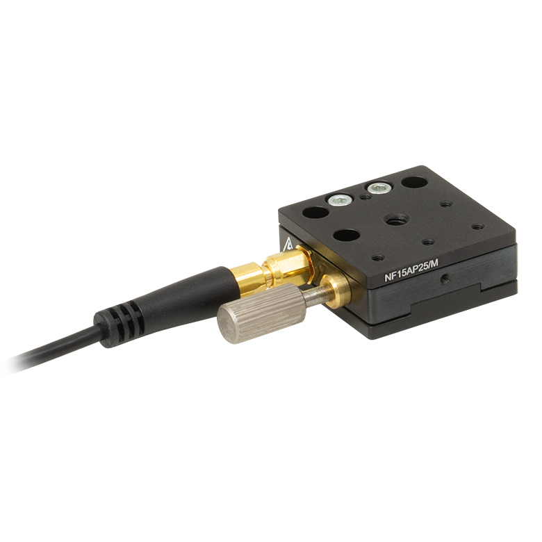 | 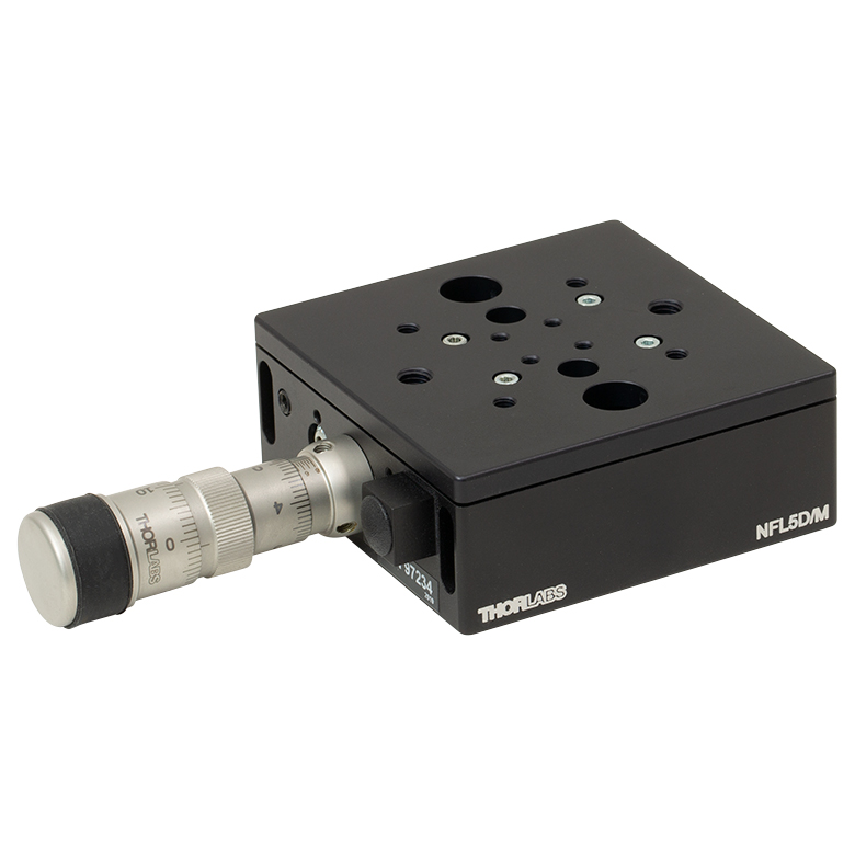 |  | 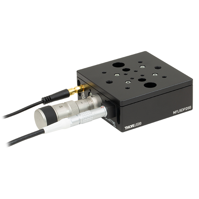 |
| Travel | 1.5 mm (0.06") + 25 µm Piezo | 5 mm (0.20") | 5 mm (0.20") + 20 µm Piezo | |
| Drive Type | Thumbscrew and Piezo Actuator | Differential Micrometer | Differential Micrometer and Open-Loop Piezo Actuator | Differential Micrometer and Closed-Loop Piezo Actuator |
| Platform Size | 1.18" x 1.18" (30.0 mm x 30.0 mm) | 2.95" x 2.95" (75.0 mm x 75.0 mm) | ||
| Possible Axis Configurations | X, XY, XYZ | X, XY, XYZ | X, XY, XYZ | X, XY, XYZ |
| Additional Details | ||||
垂直移動ステージ
当社では精密移動用のクロスローラーベアリングを用いた垂直移動ステージや、高荷重用の長距離垂直移動ステージもご用意しております。
| Vertical Stages | ||||||
|---|---|---|---|---|---|---|
| Product Family | XRN Series 9 mm Vertical Stage | XR Series 14 mm Vertical Stage | MVS Series 1/2" Vertical Stage | MVS Series 1" Vertical Stage | VAP Series 4" Vertical Stage | VAP Series 10" Vertical Stage |
| Click Photo to Enlarge | 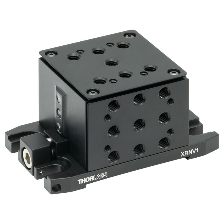 |  |  | 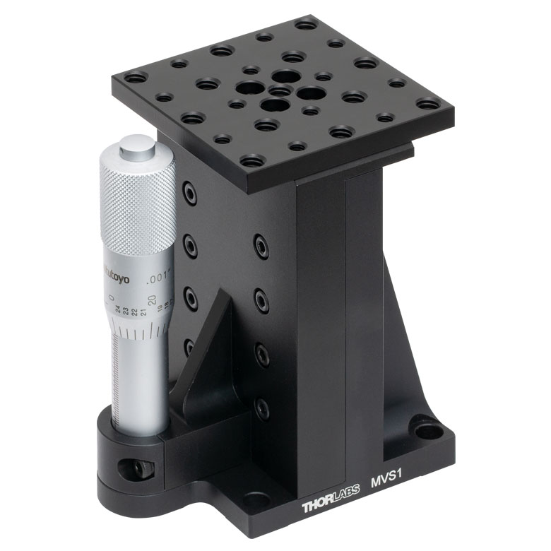 | 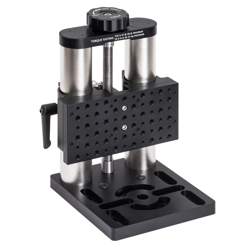 |  |
| Travel | 9.0 mm (0.35") | 14.0 mm (0.55") | 1/2" (13.0 mm) | 1" (25.0 mm) | 4" (101.6 mm) | 10" (254 mm) |
| Drive Type | Worm-Gear Driven Lift Screw | Micrometer | Adjuster Knob and Coarse Manual Positioning | |||
| Platform Size | 2.00" x 2.00" (50.7 mm x 50.7 mm) | 2.98" x 2.98" (75.7 mm x 75.7 mm) | 2.36" x 2.36" (60.0 mm x 60.0 mm) | 3.00" x 6.00" (76.2 mm 152.4 mm) | ||
| Additional Details | ||||||

 ズーム
ズーム| Item # | MT1B | MT1B/M |
|---|---|---|
| Actuator | 1/4"-170 TPI Adjustera | |
| Resolution | 0.006" (149.4 µm) Translation per Revolution | |
| Travel | 0.50" (12.7 mm) | |
| Taps | Top: 1/4"-20 (Qty. 7) Bottom: 1/4"-20 (Qty. 7) and 8-32 (Qty. 4) | Top: M6 (Qty. 7) Bottom: M6 (Qty. 7) and M4 (Qty. 4) |
| Barrel Size | Ø3/8" (Ø9.5 mm) | |
| Vertical Load Capacity (Max) | 4.4 lbs (2 kg) | |
| Horizontal Load Capacity (Max) | 7 lbs (3.2 kg) | |
MT1B/Mには、移動量が12.7 mmの1/4”-170 TPIアジャスタが付いています。このアジャスタは、手動もしくは2.0 mm六角レンチで駆動することができます。各ステージには深さ6.2 mmのM6タップ穴が7個あります。また、ステージには大きなM6ザグリ穴も2個あるため、取付けアダプタ(下記参照)に直接取り付けることができます。お手持ちのキャップスクリュを使ってブレッドボードに取り付けることも可能です。
MT1B/Mの底面には取付け用のM4タップ穴が4個あり、複数のステージを使用して2軸または3軸ステージを構築する際に使用します。詳細については「XYZアセンブリ」タブをご参照ください。
側面取付けアクチュエーターアダプタMT405(下記参照)は、ロッキングプレートとは反対側の側面にアジャスタを取り付ける場合のみ使用します。ステージのロッキングプレート側の側面にはアジャスタを取り付けられません。 ステージMT1B/Mの側面にアジャスタを取り付ける際の詳細については「アクチュエータの取り外し」のタブをご覧ください。

 ズーム
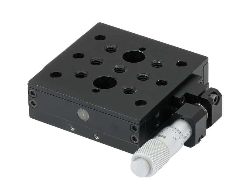
ズーム| Item # | MT1 | MT1/M |
|---|---|---|
| Actuator | 148-811ST Micrometer | 148-801ST Micrometer |
| Resolution | 0.025" Translation per Revolution | 0.5 mm Translation per Revolution |
| Travel | 0.50" | 12.7 mm |
| Engraving | 0.001" (25.4 µm) per Division | 10 µm (0.0004") per Division |
| Taps | Top: 1/4"-20 (Qty. 7) Bottom: 1/4"-20 (Qty. 7) and 8-32 (Qty. 4) | Top: M6 (Qty. 7) Bottom: M6 (Qty. 7) and M4 (Qty. 4) |
| Barrel Size | Ø3/8" (Ø9.5 mm) | |
| Vertical Load Capacity (Max) | 4.4 lbs (2 kg) | |
| Horizontal Load Capacity (Max) | 50 lbs (23 kg) | |
MT1/Mには、総移動量が12.7 mmで10 µm単位の目盛りがついたマイクロメーターヘッド148-801STが付いています。ステージには深さ6.2 mmのM6タップ穴が7個あります。また、ステージには大きなM6ザグリ穴も2個付いているので、取付けアダプタ(下記参照)に直接取り付けることができます。お手持ちのキャップスクリュを使ってブレッドボードに取り付けることも可能です。
MT1/Mの底面には取付け用のM4タップ穴が4個あり、複数のステージを使用して2軸または3軸ステージを構築する際に使用します。詳細については「XYZアセンブリ」タブをご参照ください。
側面取付けアクチュエーターアダプタMT405(下記参照)は、ロッキングプレートとは反対側の側面にマイクロメータを取り付ける場合に使用します。ステージのロッキングプレート側の側面はマイクロメータを取り付けられません。ステージMT1/Mの側面にマイクロメータを取り付ける際の詳細については「アクチュエータの取り外し」のタブをご覧ください。

 ズーム
ズーム| Item # | MT1A | MT1A/M |
|---|---|---|
| Actuator | DM10 Differential Adjuster | |
| Coarse Resolution | 0.5 mm (0.02") Translation per Revolution | |
| Coarse Range | 0.50" (12.7 mm) | |
| Fine Resolution | 25 µm (0.001") Translation per Revolution | |
| Fine Range | 250 µm (0.01") | |
| Travel | 0.50" (12.7 mm) | |
| Engraving | 0.5 µm per Division | |
| Taps | Top: 1/4"-20 (Qty. 7) Bottom: 1/4"-20 (Qty. 7) and 8-32 (Qty. 4) | Top: M6 (Qty. 7) Bottom: M6 (Qty. 7) and M4 (Qty. 4) |
| Barrel Size | Ø3/8" (Ø9.5 mm) | |
| Vertical Load Capacity (Max) | 4.4 lbs (2 kg) | |
| Horizontal Load Capacity (Max) | 50 lbs (23 kg) | |
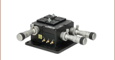
高分解能を必要とする用途向けに、移動ステージMT1A/Mには差動アジャスタDM10が付いています。差動調整ノブで1回転につき25 µm移動し、その全移動範囲は250 µmです。また、0.5 µm単位の目盛りが刻印されています。粗調整は1回転につき0.5 mm移動し、その全移動範囲は12.7 mmです。取付けカラー上のつまみネジを使って、回転のロックも可能です。 ステージには深さ6.2 mmのM6タップ穴が7個あります。
また、ステージには大きなM6ザグリ穴も2個付いているので、取付けアダプタ(下記参照)に直接取り付けることができます。お手持ちのキャップスクリュを使ってブレッドボードに取り付けることも可能です。
MT1A/Mの底面には取付け用のM4タップ穴が4個あり、複数のステージを使用して2軸または3軸ステージを構築する際に使用します。詳細については「XYZアセンブリ」タブをご参照ください。
側面取付けアクチュエーターアダプタMT405(下記参照)は、プレート側ではない側面にアジャスタを取り付けるために設計されています。ステージのロッキングプレート側の側面にはアジャスタを取り付けられませんステージMT1A/Mの側面にアジャスタを取り付ける際の詳細については「アクチュエータの取り外し」のタブをご覧ください。

 ズーム
ズーム| Item # | MT3 | MT3/M |
|---|---|---|
| Actuators | 148-811ST Micrometer | 148-801ST Micrometer |
| Resolution | 0.025" Translation per Revolution | 0.5 mm Translation per Revolution |
| Travel | 0.50" | 12.7 mm |
| Engraving | 0.001" (25.4 µm) per Division | 10 µm (0.0004") per Division |
| Taps | Top: 1/4"-20 (Qty. 7) Bottoma: 1/4"-20 (Qty. 7) and 8-32 (Qty. 4) | Top: M6 (Qty. 7) Bottoma: M6 (Qty. 7) and M4 (Qty. 4) |
| Barrel Size | Ø3/8" (Ø9.5 mm) | |
- 組立て済み、3軸XYZステージ(右手用)
- ベースプレートMT401/Mならびに直角ブラケットMT402が取り付けられた組立て済みのステージ
移動ステージMT3/Mは、標準の12.7 mmマイクロメータードライブが付いています。ステージ間の直交性を保つための精密位置決めピンを採用したモジュール設計のため、用途の変更に応じてすぐにステージを再構成することが可能です。
付属のアダプタにはM6ザグリ穴スロットが4個付いているので、キャップスクリュ(付属しません)でステージをブレッドボードに直接取り付けることが可能です。各ステージには深さ5.6 mmの取付け用M6およびM4タップ穴がそれぞれ7個と4個付いています。
MTシリーズの移動ステージは、単体(MT1シリーズ)でも、組立て済みの3軸XYZステージ(MT3シリーズ)としてもお買い求めいただけます。したがって、ステージMT3/Mを5 mmの六角レンチを用いて分解してマイクロメータの位置をカスタマイズしたり、ステージMT1/Mを3つ別々に使用することができます。詳細は「XYZアセンブリ」タブをご覧ください。

 ズーム
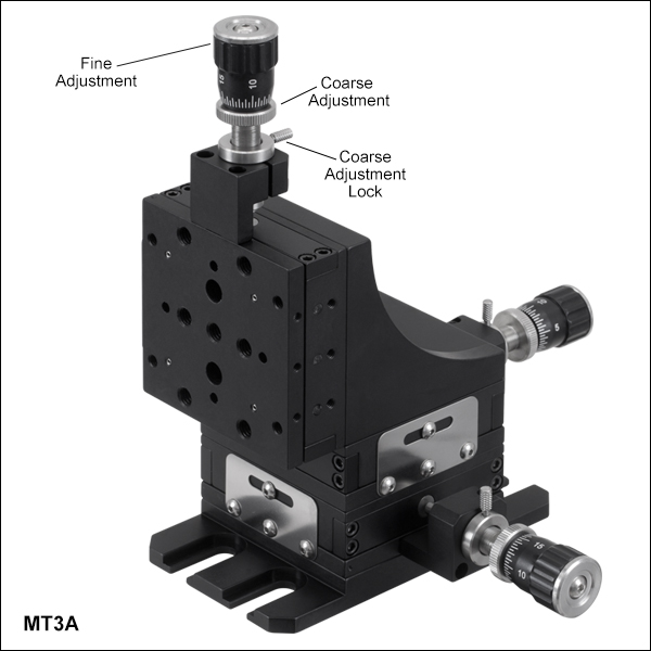
ズーム| Item # | MT3A | MT3A/M |
|---|---|---|
| Actuators | DM10 Differential Adjuster | |
| Coarse Resolution | 500 µm (0.02") Translation per Revolution | |
| Coarse Range | 0.50" (12.7 mm) | |
| Fine Resolution | 25 µm (0.001") Translation per Revolution | |
| Fine Range | 250 µm (0.01") | |
| Travel | 0.50" (12.7 mm) | |
| Engraving | 0.5 µm per Division | |
| Taps | Top: 1/4"-20 (Qty. 7) Bottoma: 1/4"-20 (Qty. 7) and 8-32 (Qty. 4) | Top: M6 (Qty. 7) Bottoma: M6 (Qty. 7) and M4 (Qty. 4) |
| Barrel Size | Ø3/8" (Ø9.5 mm) | |
- 組立て済みの右手系3軸XYZ移動ステージ
- ベースプレートMT401/Mならびに直角ブラケットMT402が取り付けられた組立て済みのステージ
移動ステージMT3A/Mは、高分解能を必要とする用途向けに差動マイクロメータが3個付属しています。粗調整は1回転につき0.5 mm移動し、その全移動範囲は12.7 mmです。また取付けカラー上のつまみネジを使って、回転をロックできます。素早く変更できるモジュール型の設計であり、またステージ間の直交性を保つために精密位置決めピンを採用しているため、用途の変更に応じてすぐにステージを再構成することが可能です。
付属のアダプタにはM6ザグリ穴スロットが4個付いているので、キャップスクリュ(付属しません)でステージをブレッドボードに直接取り付けることが可能です。各ステージには取付け用のM6タップ穴が7個、M4タップ穴が4個付いており、何れも深さは5.6 mmです。
MTシリーズの差動アジャスタ付き移動ステージは、単体(MT1Aシリーズ)でも、組立て済みの3軸XYZステージ(MT3A)としてもお買い求めいただけます。したがって、ステージMT3A/Mを5 mmの六角レンチを用いて分解し、マイクロメータの位置をカスタマイズしたり、3台のステージMT1A/Mをそれぞれ独立に使用したりすることもできます。詳細は「XYZアセンブリ」タブをご覧ください。

 ズーム
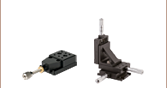
ズーム右の写真では下記のアクセサリがMTシリーズステージでどのように使用されるか示しています。

ベースプレートMT401/M:ベースプレートMT401/Mには、MTシリーズステージを光学ブレッドボードに固定するためにご使用いただける間隔が25 mmの取り付けフランジが付いています。 このベースは、XYまたはXYZの多軸構成でステージ中央のザグリ穴が使用できない時に利用できます。ベースプレートには、M6キャップスクリュ(5 mm六角)が2個付属しています。このベースプレートはMT3/MおよびMT3A/Mに付属します。
直角ブラケットMT402: MT402は、2つのステージを互いに直角に取り付けることができます。このプレートは、XZまたはXYZ配列でステージを組み立てる際に必要となります。この直角ブラケットにはM6キャップスクリュ(5 mm六角レンチ使用)が4個付属します。ボールドライバおよび六角レンチはこちらで別売りにてご用意しております。この直角ブラケットはMT3/MおよびMT3A/Mに付属します。
側面取付けアクチュエーターキットMT405: MT405は、アクチュエータの位置をステージ後部から側面へと変えることができます。取付け用の4つのキャップスクリュが付属します。アクチュエータをMTシリーズステージの側面に取り付ける際の詳細については、「アクチュエータの取り外し」タブをご覧ください
アダプタープレート(フレクシャーステージ用アクセサリ)MT406/M: MT406/Mは、2つのM6キャップスクリュでMTシリーズのステージ上部に直接固定することができます。この製品は、当社のMBTおよびMAXシリーズフレクシャーステージアクセサリの3 mm幅アライメントキーに互換性があります。このアダプタープレートは、ファイバ結合用ステージの構成に適しています。
ボールベアリング機構 ボールベアリング機構 | +回転プラットフォーム |