 Products Home
Polaris® Kinematic Collimators
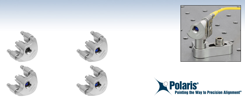
- Kinematic, Fixed Focus Collimators for FC/PC-Terminated Fiber
- Pre-Aligned for 532, 633, 780, or 850 nm Wavelengths
- Pitch and Yaw Adjustment Range of ±5°
- Minimal Temperature-Dependent Hysteresis
PF2F53
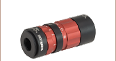
Kinematic, Fixed Focus Collimator, 532 nm
PF2F78
Kinematic, Fixed Focus Collimator, 780 nm
PF2F63
Kinematic, Fixed Focus Collimator, 633 nm
PF2F85
Kinematic, Fixed Focus Collimator, 850 nm
Application Idea
The PF2F63 kinematic collimator is used to collimate the output of a P1-S405-FC-1 fiber patch cable.


Please Wait
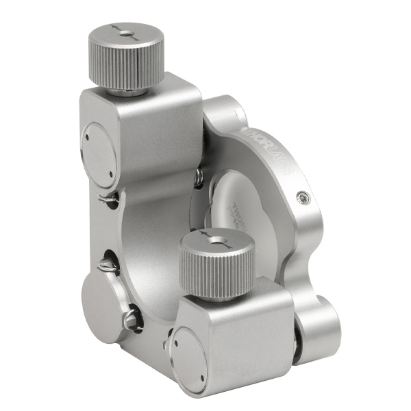
Click to Enlarge
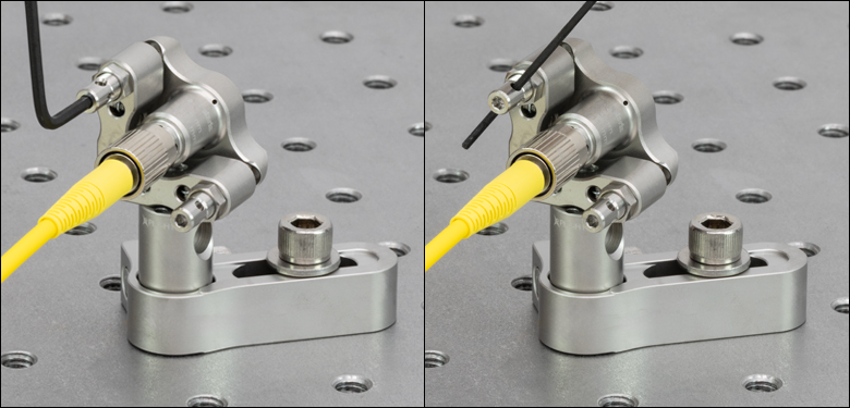
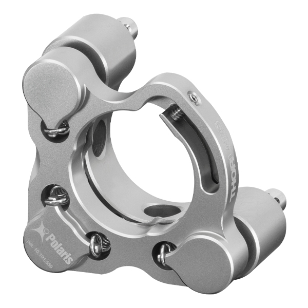
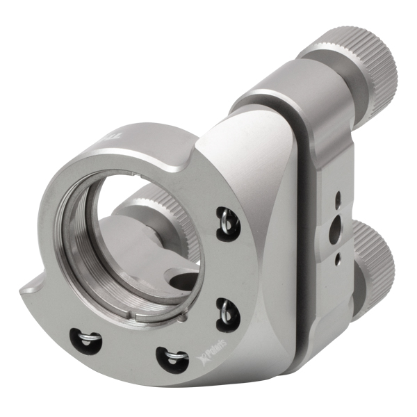
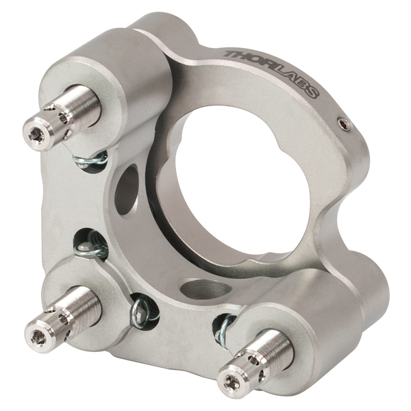
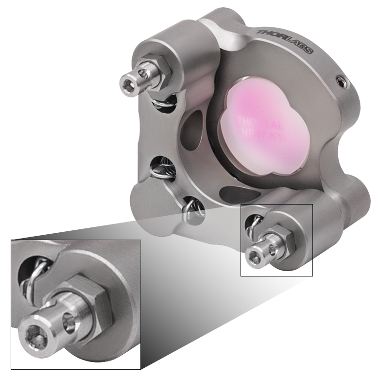
Figure 1.1 There are two methods for adjusting the angle of our Polaris® kinematic collimators: using a 5/64" (2.0 mm) hex key in the end of the adjuster, or using the same or smaller hex key through the Ø0.07" (Ø1.8 mm) adjuster side holes
| Quick Links | |
|---|---|
| Kinematic Collimators | |
| Lock Nut | |
| Locking Collar & Spanner Wrench | |
| 5/64" Hex Key Adjusters | |
| Torque Wrenches |
Features
- Machined from Heat-Treated Stainless Steel with Low Coefficient of Thermal Expansion (CTE)
- Pre-Aligned Fiber Collimators with FC/PC Connectors (Three 2.2 mm Wide Key Slots) for Single Mode Patch Cables
- Collimators Aligned for 532, 633, 780, or 850 nm Wavelengths
- Hardened Stainless Steel Ball Contacts with Sapphire Seats for Durability and Smooth Movement
- 8-32 (M4 x 0.7) Threaded Mounting Hole for Post Mounting
- Matched Actuator/Body Pairs Provide Smooth Kinematic Adjustment
- Testing Guarantees ≤2 μrad Deviation after 16 °C Temperature Cycle (See the Test Data Tab for Details)
- Passivated Stainless Steel Surface Ideal for Vacuum and High-Power Laser Cavity Applications
- Custom Mount Configurations and Alignment Wavelengths Available by Contacting Tech Sales
Polaris® Kinematic, Fixed Focus Collimators combine the high-quality beam output of our fixed focus collimation packages with the remarkable mechanical properties of our Polaris® mounts, making them the ultimate solution for fiber collimation applications requiring stringent long-term alignment stability. These fiber collimation packages are pre-aligned to collimate light from an FC/PC-terminated fiber with diffraction-limited performance. Due to chromatic aberration, the effective focal length (EFL) of the aspheric lens is wavelength dependent. The alignment wavelength indicates the wavelength of ideal beam divergence (see the Graphs and Calculations tabs for more information).
The aspheric lens is factory aligned for collimation at the alignment wavelength when connected to its specified single mode fiber patch cable. In addition, the aspheric lens has an AR coating on both sides that minimizes surface reflections (see the Graphs tab). For some applications they may also be used at other wavelengths within the AR coating range; please refer to the theoretical divergence plot for each collimator to determine if it is appropriate for your application. The operating temperature range for these collimators is -30 °C to 200 °C.
These fiber collimators are optimized for use with single mode fiber patch cables. For improved performance, we recommend using these collimators with our AR-coated single mode fiber optic patch cables. These cables feature an antireflective coating on one fiber end for increased transmission and improved return loss at the fiber-to-free-space interface. Please note performance specifications are guaranteed only when used with single mode fiber.
Design
Machined from heat-treated stainless steel, Polaris mounts utilize precision-matched adjusters with ball contacts and sapphire seats to provide smooth kinematic adjustment. As shown in the Test Data tab, these mounts have undergone extensive testing to ensure high-quality performance. The Polaris design addresses all of the common causes of beam misalignment; please refer to the Design Features tab for detailed information.
Post Mounting
The design of the kinematic elements on these mounts prevents the user having to put their hand in front of the collimator when doing a kinematic adjustment or having to uninstall the collimator to mount this onto a post. Unlike the traditional counterbore on our Polaris mounts, this design comes with two 8-32 (M4 x 0.7) threaded holes for mounting on a post; one 8-32 (M4 x 0.7) cap screw is included with each collimator. They also feature Ø2 mm alignment pin holes around each mounting hole, allowing for precision alignment when paired with our counterbored Ø1/2" or Ø1" Posts for Polaris Mounts. They can also be mounted on threaded posts, however caution should be used when using anything other than the included cap screw to ensure that the screw being used does not make contact with the collimator itself.
Cleanroom and Vacuum Compatibility
All Polaris collimators sold on this page are designed to be compatible with cleanroom and vacuum applications. See the Design Features tab for more information.
Alternatives
We offer another line of adjustable collimation packages called FiberPorts that are well suited for a wide range of wavelengths. These are ideal solutions for adjustable, compact fiber couplers. For other collimation and coupling options, please see our Collimator Guide tab or contact Tech Sales.
| Item #a | PF2F53(/M) | PF2F63(/M) | PF2F78(/M) | PF2F85(/M) |
|---|---|---|---|---|
| Collimator Specifications | ||||
| Alignment Wavelengtha | 532 nm | 633 nm | 780 nm | 850 nm |
| Lens AR Coating | Ravg < 0.5%, 350 - 700 nm | Ravg < 0.5%b, 650 - 1050 nm | Ravg < 0.5%, 650 - 1050 nm | |
| Output Beam Diameterc | 2.1 mm | 2.41 mm | ||
| Full-Angle Beam Divergenced | 0.02° | 0.022° | 0.026° | 0.03° |
| Numerical Aperture | 0.25 | 0.26 | 0.25 | |
| Focal Length Calculated at Alignment Wavelength | 10.90 mm | 10.99 mm | 11.07 mm | 11.12 mm |
| Connector Type | FC/PC, Three 2.2 mm Wide Key Slots | |||
| Mount Specifications | ||||
| Adjuster Drive | 5/64" (2.0 mm) Hex, Ø0.07" (Ø1.8 mm) Side Adjustment Holes | |||
| Adjuster Pitch | 3/16"-130 Matched Actuator/Body Pairs | |||
| Measured Point-to-Point Mechanical Resolution per Adjuster |
5 µrad (Typical) 2 µrad (Achievable) |
|||
| Resolutione | ~11 mrad/rev | |||
| Mechanical Angular Range (Nominal) | ±5° | |||
| Beam Deviationf After Thermal Cycling | <2.0 μrad | |||
| Mounting | Two 8-32 (M4 x 0.7) Threaded Holes at 90° | |||
| Alignment Pin Holes | Two Ø2 mm Holes for DIN 7-m6 Ground Dowel Pin at Each Mounting Hole | |||
| Vacuum Compatibilityg | 10-9 Torr at 25 °C with Proper Bake Out; 10-5 Torr at 25 °C without Bake Out DuPont Krytox® LVP High-Vacuum Grease Vapor Pressure: 10-13 Torr at 20 °C ,10-5 Torr at 200 °C EPO-TEK® 353ND (353NDPK) Epoxy Meets Low Outgassing Standards NASA ASTM E595, Telcordia GR-1221 |
|||
| Operating Temperature Range | -30 to 200 °C | |||
| Table 3.1 Coating Information | ||
|---|---|---|
| Coating Designation | A | B |
| Applicable Item #s | PF2F53(/M) | PF2F63(/M), PF2F78(/M), PF2F85(/M) |
| Coating Range | 350 - 700 nm | 650 - 1050 nm |
| Reflectance | Ravg < 0.5% within Coating Range | Ravg < 0.5% within Coating Range |
Click to Enlarge
Click Here for Raw Data
Figure 3.3 The blue shaded region indicates the specified 350 - 700 nm wavelength range for optimum performance.
Click to Enlarge
Click Here for Raw Data
Figure 3.2 The blue shaded region indicates the specified 350 - 700 nm wavelength range for optimum performance.
Click to Enlarge
Click Here for Raw Data
Figure 3.4 This plot shows the typical angular deviation of the collimated beam using the same fiber in the top, side, or diagonal FC/PC key orientations for any of our kinematic collimators. Standard deviation of the pitch and yaw are typically <10 µrad and <20 μrad, respectively, for a given fiber orientation. This deviation is dependent on the alignment of the fiber tip with each rotation axis of the sleeve and will vary depending on the patch cable used.
Click to Enlarge
Click Here for Raw Data
Figure 3.6 This plot shows the theoretical divergence of a beam collimated by the PF2F53(/M) collimator for wavelengths from 400 - 700 nm.
Click to Enlarge
Click Here for Raw Data
Figure 3.5 This plot shows the theoretical diameter of a beam output from the PF2F53(/M) collimator.
Click to Enlarge
Click Here for Raw Data
Figure 3.8 This plot shows the theoretical divergence of a beam collimated by the PF2F63(/M) collimator for wavelengths from 600 - 1050 nm.
Click to Enlarge
Click Here for Raw Data
Figure 3.7 This plot shows the theoretical diameter of a beam output from the PF2F63(/M) collimator.
Click to Enlarge
Click Here for Raw Data
Figure 3.10 This plot shows the theoretical divergence of a beam collimated by the PF2F78(/M) collimator for wavelengths from 600 - 1050 nm.
Click to Enlarge
Click Here for Raw Data
Figure 3.9 This plot shows the theoretical diameter of a beam output from the PF2F78(/M) collimator.
Click to Enlarge
Click Here for Raw Data
Figure 3.12 This plot shows the theoretical divergence of a beam collimated by the PF2F85(/M) collimator for wavelengths from 600 - 1100 nm.
Click to Enlarge
Click Here for Raw Data
Figure 3.11 This plot shows the theoretical diameter of a beam output from the PF2F85(/M) collimator.
Polaris® Kinematic Collimators Test Data
All of the Polaris Kinematic Collimators have undergone extensive testing to ensure high-quality performance. After mounting a PF2F63 collimator to a PLS-C15 (collimator 1) or PLS-P150 (collimator 2) Ø1" stainless steel post, the assembly was secured to a stainless steel optical table in a temperature-controlled environment. The beam output by each collimator was then measured by a position sensing detector. While these collimators are designed for use with the PLS-Cxx series of counterbored posts, they can also be mounted on threaded posts; however, caution should be used when using anything other than the included cap screw to ensure that the screw being used does not make contact with the collimator itself.
Positional Repeatability After Thermal Shock
Purpose: This testing was done to determine how reliably the kinematic collimator returns the beam, without hysteresis, to its initial position. These measurements show that the alignment of the optical system is unaffected by the temperature shock.
Procedure: The temperature of two PF2F63 kinematic collimators, collimator 1 mounted on a PLS-C15 counterbored post and collimator 2 mounted on a PLS-P150 threaded post, was elevated and maintained for a given soak time. Then the temperature of each of the collimators was returned to the starting temperature. The results of these tests are shown in Figures 4.1 - 4.3.
Results: As can be seen in the plots in Figures 4.1 - 4.3, when the Polaris collimators were returned to their initial temperature, the angular position (both pitch and yaw) of the collimators returned to within 2.0 µrad of their initial positions. The performance of each collimator was tested further by subjecting them to repeated temperature change cycles. After each cycle, the collimator's position reliably returned to within 2.0 µrad of its initial position.
For Comparison: To get a 2.0 µrad change in the collimator's position, the 130 TPI adjuster on a Polaris collimator needs to be rotated by only 0.0655° (1/5500 of a turn). A highly skilled operator might be able to make an adjustment as small as 0.3° (1/1200 of a turn), which corresponds to a 9 µrad change in position.
Conclusions: The Polaris kinematic collimators are high-quality, ultra-stable mounts that will reliably return the collimated beam after cycling through a temperature change. As a result, Polaris collimators are ideal for use in applications that require long-term alignment stability.
Click to Enlarge
Figure 4.1 These plots show the pitch and yaw deviation of collimator 1 (a PF2F63 collimator mounted on a PLS-C15 counterbored post) as it undergoes a heating and cooling cycle.
Click to Enlarge
Figure 4.2 These plots show the pitch and yaw deviation of collimator 2 (a PF2F63 collimator mounted on a PLS-P150 threaded post) as it undergoes a heating and cooling cycle.
Click to Enlarge
Figure 4.3 This plot shows the final angular position of two PF2F63 collimators for 10 consecutive thermal shock tests. Collimator 1 is mounted on a PLS-C15 counterbored post while collimator 2 is mounted on a PLS-P150 threaded post. The change in temperature is the difference between the starting temperature and the temperature at the end of the test and includes factors such as the variation in room temperature.
Click to Enlarge
Figure 5.1 Design Features of the Polaris Kinematic Collimators
Several common factors typically lead to beam misalignment in an optical setup. These include temperature-induced hysteresis of the optic's position, crosstalk, drift, and backlash. Polaris mounts are designed specifically to minimize these misalignment factors and thus provide extremely stable performance. Hours of extensive research, multiple design efforts using sophisticated design tools, and months of rigorous testing went into choosing the best components to provide an ideal solution for experiments requiring ultra-stable performance from a kinematic mount.
Thermal Hysteresis
The temperature in most labs is not constant due to factors such as air conditioning, the number of people in the room, and the operating states of equipment. Thus, it is necessary that all mounts used in an alignment-sensitive optical setup be designed to minimize any thermally induced alignment effects. Thermal effects can be minimized by choosing materials with a low coefficient of thermal expansion (CTE), like stainless steel. However, even mounts made from a material with a low CTE do not typically return the optic to its initial position when the initial temperature is restored. All the critical components of the Polaris kinematic collimators are heat treated prior to assembly since this process removes internal stresses that can cause a temperature-dependent hysteresis. As a result, the alignment of the optical system will be restored when the temperature of the mount is returned to the initial temperature.
Crosstalk
Crosstalk is minimized by carefully controlling the dimensional tolerances of the front and back plates of the mount so that the pitch and yaw actuators are orthogonal. In addition, sapphire seats are used at all three contact points. Standard metal-to-metal actuator contact points will wear down over time. The polished sapphire seats of the Polaris mounts, in conjunction with the hardened stainless steel actuator tips, maintain the integrity of the contact surfaces over time.
Drift and Backlash
In order to minimize the positional drift of the collimator and backlash, it is necessary to limit the amount of play in the adjuster as well as the amount of lubricant used. When an adjustment is made to the actuator, the lubricant will be squeezed out of some spaces and built up in others. This non-equilibrium distribution of lubricant will slowly relax back into an equilibrium state. However, in doing so, this may cause the position of the front plate of the mount to move. The Polaris mounts use adjusters matched to the body or bushings that exceed all industry standards so very little adjuster lubricant is needed. As a result, alignment of the Polaris mounts is extremely stable even after being adjusted (see the Test Data tab for more information). In addition, these adjusters have a smooth feel that allows the user to make small, repeatable adjustments.
Vacuum Compatible and Low Outgassing
All Polaris mounts sold on this page are designed to be compatible with cleanroom and vacuum chamber applications. They are chemically cleaned using the Carpenter AAA passivation method to remove sulfur, iron, and contaminants from the surface. After passivation, they are assembled in a clean environment and then double vacuum bagged to eliminate contamination when transported into a cleanroom.
The sapphire contacts and the collimating lens are each bonded into place using a NASA-approved low outgassing procedure. In addition, DuPont LVP High-Vacuum (Krytox) Grease, an ultra-high vacuum compatible, low outgassing PTFE grease, is applied to the adjusters. These features provide high vacuum compatibility and low outgassing performance. When operating at pressures below 10-5 Torr, we highly recommend using an appropriate bake out procedure prior to installing the mount in order to minimize contamination caused by outgassing. Please note that the 8-32 and M4 x 0.7 cap screws included with the Polaris mounts are not rated for pressures below 10-5 Torr. The plastic caps included with each part are not vacuum compatible.
Cleanroom-Compatible Packaging
Each vacuum-compatible Polaris mount is packaged within two vacuum bag layers after assembly in a clean environment. The vacuum-tight fit of the bags stabilizes the mount, limiting translation of the front plate due to shocks during transportation. The tight fit also minimizes rubbing against the bag, preventing the introduction of bag material shavings that would contaminate the clean mount.
In the vacuum-sealing process, moisture-containing air is drawn out of the packaging. This eliminates unwanted reactions on the surface of the mount without the need for desiccant materials. The vacuum bags protect the mount from contamination by air or dust during transport and storage, and the double-vacuum bag configuration allows for a straightforward and effective cleanroom entry procedure. The outer bag can be removed outside of the cleanroom, allowing the contaminant-free inner bag to be placed into a clean container and transferred into the cleanroom while retaining the benefits of vacuum-bag packaging. Inside the cleanroom, the mount can be removed from the inner bag when ready for use.

The calculations below can be used to theoretically approximate the divergence angle, maximum waist distance, and output diameter of a beam through a fiber collimator. For a macro-enabled Excel file with these and other useful calculations when working with fiber collimators, please click on the Fiber Collimator Calculator button. It is recommended to download and open the file in the Excel desktop application, as some features are not supported in the web version of Excel. The file includes calculations for the following parameters:
- Full Divergence Angle
- Maximum Waist Distance
- Output Beam Diameter
- Beam Diameter at a Certain Distance Away
- Fiber Coupling Efficiency
Please note that macros must be enabled to use the Excel file. To enable macros, click the "Enable Content" button in the yellow message bar upon opening the file.
Theoretical Approximation of the Divergence Angle
The full-angle beam divergence listed in the specifications tables is the theoretically-calculated value associated with the fiber collimator. This divergence angle is easy to approximate theoretically using the formula below as long as the light emerging from the fiber has a Gaussian intensity profile. Consequently, the formula works well for single mode fibers, but it will underestimate the divergence angle for multimode (MM) fibers since the light emerging from a multimode fiber has a non-Gaussian intensity profile.
The full divergence angle (in degrees) is given by
where MFD is the mode field diameter and f is the focal length of the collimator. (Note: MFD and f must have the same units in this equation).
Example:
When the PF2F53(/M) collimator (f ≈ 10.9 mm; not exact since the design wavelength is 532 nm) is used to collimate 515 nm light emerging from a 460HP fiber (MFD = 3.5 µm), the divergence angle is approximately given by
θ ≈ (0.0035 mm / 10.9 mm) * (180 / 3.1416) = 0.018°.
Theoretical Approximation of the Maximum Waist Distance
The maximum waist distance, which is the furthest distance from the lens the waist can be located in order to maintain collimation, may be approximated by
where f is the focal length of the collimator, λ is the wavelength of light used, and MFD is the mode field diameter. (Note: λ, MFD, and f must have the same units in this equation).
Example:
When the PF2F53(/M) collimator (f = 10.9 mm) is used with the P1-460B-FC-1 patch cable (MFD ≈ 4.0 µm; calculated approximate value) and 532 nm light, then the maximum waist distance is approximately
zmax = 10.9 mm + [(2 * (10.9 mm)2 * 0.000532 mm) / (3.1416 * (0.004 mm)2)] = 2526 mm.
Theoretical Approximation of the Output Beam Diameter
The output beam diameter can be approximated from
where λ is the wavelength of light being used, MFD is the mode field diameter, and f is the focal length of the collimator. (Note: MFD and f must have the same units in this equation).
Example:
When the PF2F53(/M) collimator (f = 10.9 mm) is used with the P1-405B-FC-1 patch cable (MFD ≈ 3.4 µm; calculated approximate value) and 532 nm light, the output beam diameter is
d ≈ (4 * 0.000532 mm) * [10.9 mm / (3.1416 * 0.0034 mm)] = 2.17 mm.
ファイバーコリメーターセレクションガイド
コリメータの種類または画像をクリックすると、各コリメータの詳細がご覧いただけます。
| Type | Description | |
|---|---|---|
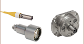
| 焦点固定型FC、APC、SMAファイバーコリメータ | 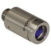 | こちらのファイバーコリメーターパッケージは、FC/PC、FC/APC、またはSMAコネクタ付きファイバからの出射光をコリメートするように、予めアライメントされています。各コリメーターパッケージは、405 nm~4.55 µmの波長で回折限界性能が得られるように工場で調整されています。設計波長以外でコリメータを使用することは可能ですが、色収差が生じるため最適な性能が得られるのは設計波長においてのみです。非球面レンズの実際の焦点距離は、色収差により波長に依存します。 |
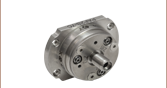
| エアスペース型複レンズ、大径ビームコリメータ |  | 大径ビーム(Ø5.3 mm~Ø8.5 mm)用として、FC/PC、FC/APC、SMAコネクタ付きエアスペース型複レンズコリメータをご用意しています。こちらのコリメーターパッケージは、FCやSMAコネクタ付きファイバからの出射光をコリメートし、設計波長で回折限界性能が得られるように工場で予めアライメントされています。 |
| トリプレットレンズコリメータ |  | 高品質なトリプレットコリメーターパッケージは、エアスペース型トリプレットレンズを使用しており、非球面レンズを用いたコリメータよりも優れたビーム品質が得られます。収差の小さいトリプレットを用いることの利点は、M2値として1(ガウシアン)に近い値が得られ、広がり角や波面エラーが小さくなることなどです。 |
| マルチモードファイバ用アクロマティックコリメータ |  | 高NAアクロマティックコリメータは、メニスカスレンズとアクロマティック複レンズを組み合わせることで、可視~近赤外スペクトル域において球面収差の少ない優れた性能を発揮します。高NAのマルチモードファイバ用に設計されているため、オプトジェネティクスやファイバーフォトメトリの用途に適しています。 |
| 反射型コリメータ | 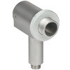 | 金属コーティング反射型コリメータは、90°軸外放物面(OAP)ミラーをベースにしています。レンズと違い、ミラーは広い波長範囲にわたり焦点距離が変化しません。この特性により、軸外放物面(OAP)ミラーを用いたコリメータは広い波長範囲に対応させるための調整が不要となるため、多色光を用いる用途に適しています。当社の反射型コリメータはシングルモードファイバからの光のコリメートには適していますが、シングルモードファイバへの結合には適していません。これらのコリメータにはUV強化型アルミニウムコーティングと保護膜付き銀コーティングの製品をご用意しており、それらにはFC/PC、FC/APCまたはSMAコネクタが取り付けられています。 |
| コンパクト反射型コリメータ |  | このコンパクトな反射型コリメータには、保護膜付き銀コーティングが施された90°軸外放物面(OAP)ミラーが組み込まれています。OAPミラーの焦点距離は波長に依存しないため、多色光用として適しています。 この固定式の反射型コリメータは、シングルモードファイバやマルチモードファイバからの出射光のコリメート用、およびマルチモードファイバへの光結合用として推奨しています。 これらのコリメータは当社の16 mmケージシステムに直接取り付けられます。 光入射用として、FC/PC、FC/APCまたはSMAコネクタの取り付けられた製品をご用意しています。 |
| 調整機能付き反射型コリメータ |  | 調整機能付き反射型コリメータは、保護膜付き銀コーティングが施された90°軸外放物面(OAP)ミラーをベースにしています。ファイバ-OAP間の距離が調整可能であり、またOAPミラーが波長によらず一定の焦点距離を有します。そのため、シングルモードまたはマルチモードファイバからの多色光をコリメートしたり、あるいは逆に多色光をそれらのファイバに結合したりすることができ、その際に最適化のための調整も可能です。これらの調整機能付きコリメータは15.0 mmまたは33.0 mmの反射焦点距離を有し、FC/PC、FC/APC、またはSMAコネクタ付きの製品をご用意しています。 |
| FiberPort |  | こちらのコンパクトで極めて安定なFiberPortマイクロポジショナは、FC/PC、FC/APCまたはSMAコネクタ付き光ファイバとの光の入出射用として、安定で使いやすいプラットフォームです。シングルモード、マルチモードまたは偏波保持ファイバと組み合わせて使用することができ、ポスト、ステージ、プラットフォーム、レーザなどに取り付けることができます。組み込まれている非球面またはアクロマティックレンズのARコーティングは5種類から選択でき、また5軸のアライメント調整(3つの移動調整と2つの角度調整)が可能です。コンパクトでアライメントの長期安定性に優れたFiberPortは、ファイバへの光の結合、コリメート、組み込み用途(OEM用途)などに適しています。 |
| 調整可能型ファイバーコリメータ |  | このコリメータは、FC/PC、FC/APCまたはSMAコネクタに接続するよう設計されており、内部にはARコーティング付き非球面レンズが取付けられています。非球面レンズとファイバ先端との距離は、焦点距離の変化を補正したり、波長や対象までの距離に合わせて再コリメートしたりするために調整することができます。 |
| アクロマティックファイバーコリメータ、焦点調整可能 |  | 焦点調整の可能な当社のアクロマティックファイバーコリメータは、20 mm、40 mmまたは80 mmの有効焦点距離(EFL) を有し、その光学素子のARコーティングは3種類の広帯域ARコーティングから選ぶことができます。また、接続用コネクタの種類としては、FC/PC、FC/APCまたはSMA905をご用意しています。4枚のレンズを使用したエアスペース型設計であるため、非球面レンズのコリメータに比べてビーム品質に優れ(1に近いM2)、波面誤差は小さくなっています。これらのコリメータは自由空間光のファイバへの結合や、ファイバからの出射光のコリメートなどにご使用いただけます。また、距離をとって配置した2つのコリメータを用いて光を結合させると、光が2番目のコリメータに入る前にそのビームを操作することが可能になります。 |
| ズーム機能付きファイバーコリメータ |  | こちらのコリメータは、ビームをコリメートしたまま、6~18 mmの範囲で焦点距離を変えることができます。そのため、コリメートした状態でビームサイズを変更できます。このデバイスは、用途に適した固定のファイバーコリメータを探す手間を省けるという利点に加え、1つで様々な幅広い用途に対応することができます。FC/PC、FC/APCまたはSMA905コネクタが付いており、反射防止コーティングは3種類からお選びいただけます。 |
| シングルモードファイバーピグテール付きコリメータ | 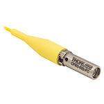 | シングルモードファイバーピグテール付きコリメータは、長さ1メートルのファイバとそれに対して予めアライメントされたARコーティング付き非球面レンズとで構成されており、532 nm、633 nm、780 nm、850 nm、1030 nm、1064 nm、1310 nm、1550 nmの8波長用の製品をご用意しています。コーティング波長域内のどの波長でもコリメートできますが、設計波長からずれると結合損失が増加します。 |
| 偏波保持ファイバーピグテール付きコリメータ |  | 偏波保持ファイバーピグテール付きコリメータは、長さ1メートルのファイバとそれに対して予めアライメントされたARコーティング付き非球面レンズとで構成されており、633 nm、780 nm、980 nm、1064 nm、1550 nmの5波長用の製品をご用意しています。波長やコネクタについてはカスタム仕様も対応可能です。筐体の外側にはスロー軸と平行なラインが刻印されています。これは入射光の偏光面をアライメントする際の目安としてお使いいただけます。コーティング波長域内のどの波長でもコリメートできますが、設計波長からずれると結合損失が増加します。 |
| GRINレンズコリメータ |  | GRINレンズファイバーコリメータは、630~1550 nmの範囲内の様々な波長に対してアライメントされた製品をご用意しており、FCまたはAPCコネクタ付きもしくはコネクタ無しのタイプからお選びいただけます。この有効径Ø1.8 mmのGRINレンズコリメータは、ファイバへの後方反射光を抑えるためにARコーティングが施されており、標準のシングルモードファイバまたはグレーデッドインデックス(GI)マルチモードファイバに結合されています。 |
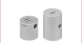
| GRINレンズ |  | この屈折率分布型(GRIN)レンズは630 nm、830 nm、1060 nm、1300 nm、または1560 nmの波長用にARコーティングが施されており、光ファイバから出射した光が自由空間の光学系を通過して再度別のファイバに入射するまでの各用途にご利用いただけます。また半導体レーザの出射光のファイバへの結合、ファイバからの出射光のディテクタへの集光、レーザ光のコリメートなどにも適しています。このGRINレンズは当社の ピグテール付きガラスフェルールやGRINレンズ/フェルール用スリーブと組み合わせてお使いいただくこともできます。 |
当社では、側面固定型、SMネジ付き、低歪み、 ピエゾアジャスタ付き、上部アジャスタ付き、接着固定式などのキネマティック光学マウントのほかに、固定式モノリシックミラーマウント、固定式光学マウント、XY移動マウント、5軸キネマティックマウント、キネマティックプラットフォームマウントなど、様々なPolarisマウントをご用意しております。下の表では、当社のすべてのPolarisマウントのラインナップを、マウントのタイプ、光学素子取付け穴のサイズ、光学素子の保持方法、アジャスタの種類(固定式マウントの場合は用途)などで分類して表記しています。また、Table 103Gに示すように、Polarisマウント用に設計されたアクセサリもご用意しています。下の表では、簡潔に表記するために冒頭の「POLARIS」を省略し、型番末尾のみを掲載しています。下の写真をクリックすると拡大できます。
| Table 103A Polaris Mount Optic Retention Methods | |||
|---|---|---|---|
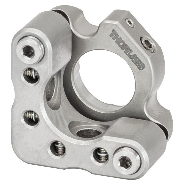
| Side Lock | SM Threaded | Low Distortion | Glue-In |
 |  |  |  |
| Table 103B Polaris Mount Adjuster Types | |||||
|---|---|---|---|---|---|
| Side Hole | Hex | Adjuster Knobs | Adjuster Lock Nuts | Piezo Adjusters | Vertical-Drive Adjusters |
 |  | 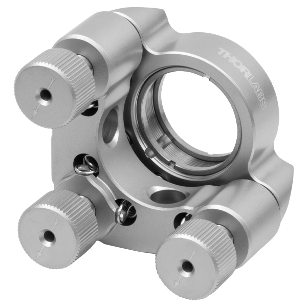 | 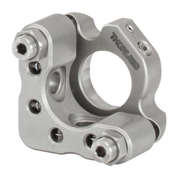 | 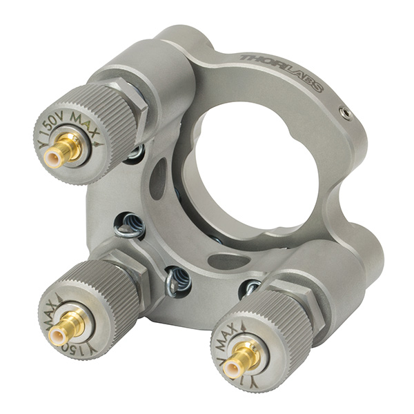 |  |
| Table 103C Polaris Kinematic Mounts for Round Optics | ||||
|---|---|---|---|---|
| Optic Retention Method | Side Lock | SM Threaded | Low Distortion | Glue-In |
| Ø1/2" Optics | ||||
| 2 Side Hole Adjusters | - | - | - | -K05C4 -K05G4 |
| 2 Hex Adjusters | -K05S1 | -K05T1 | -K05F1 | - |
| 2 Adjusters with Lock Nuts | -K05S2 | -K05T2 | -K05F2 | - |
| 2 Piezoelectric Adjusters | -K05P2 | - | - | - |
| 2 Vertical Adjusters | -K05VS2 -K05VS2L | - | - | - |
| 3 Hex Adjusters | -K05 | - | - | - |
| 3 Adjusters with Lock Nuts | - | -K05T6 | -K05F6 | - |
| 3 Adjuster Knobs (Tip/Tilt/Z) & 2 Hex Adjusters (X/Y) | - | -K05XY | - | - |
| Ø19 mm (3/4") Optics | ||||
| 2 Side Hole Adjusters | -K19S4 | - | -K19F4/M | -K19G4 |
| Ø25 mm Optics | ||||
| 2 Side Hole Adjusters | -K25S4/M | - | -K25F4/M | - |
| Ø1" Optics | ||||
| 2 Side Hole Adjusters | -K1S4 | - | - | -K1C4 -K1G4 |
| 2 Hex Adjusters | -K1E2 -K1-2AH | -K1T2 | -K1F2 | - |
| 2 Adjuster Knobs | - | -K1T1 | -K1F1 | - |
| 2 Piezoelectric Adjusters | -K1S2P | - | - | - |
| 2 Vertical Adjusters | -K1VS2 -K1VS2L | - | - | - |
| 3 Side Hole Adjuster | -K1S5 | - | - | - |
| 3 Hex Adjusters | -K1E3 -K1-H | -K1T3 | - | - |
| 3 Adjuster Knobs | -K1E -K1 | -K1T | -K1F | - |
| 3 Piezoelectric Adjusters | -K1S3P | - | - | - |
| 3 Adjuster Knobs (Tip/Tilt/Z) & 2 Hex Adjusters (X/Y) | - | -K1XY | - | - |
| Optic Retention Method | Side Lock | SM Threaded | Low Distortion | Glue-In |
| Ø1.5" Optics | ||||
| 2 Side Hole Adjusters | -K15S4 | - | -K15F4 | - |
| 2 Vertical Adjusters | -K15VS2 -K15VS2L | - | - | - |
| 3 Adjuster Knobs (Tip/Tilt/Z) & 2 Hex Adjusters (X/Y) | - | -K15XY | - | - |
| Ø50 mm Optics | ||||
| 2 Side Hole Adjusters | -K50S4/M | - | -K50F4/M | - |
| Ø2" Optics | ||||
| 2 Hex Adjusters | -K2S2 | -K2T2 | -K2F2 | - |
| 2 Adjuster Knobs | -K2S1 | -K2T1 | -K2F1 | - |
| 2 Piezoelectric Adjusters | -K2S2P | - | - | - |
| 2 Vertical Adjusters | -K2VS2 -K2VS2L | - | - | - |
| 3 Hex Adjusters | -K2S3 | -K2T3 | -K2F3 | - |
| 3 Adjuster Knobs | -K2 | -K2T | -K2F | - |
| Ø3" Optics | ||||
| 2 Side Hole Adjusters | -K3S4 | - | - | - |
| 3 Side Hole Adjusters | -K3S5 | - | - | - |
| Ø4" Optics | ||||
| 2 Side Hole Adjusters | - | - | -K4F4 | - |
| Ø6" Optics | ||||
| 2 Side Hole Adjusters | - | - | -K6F4 | - |
| Table 103D Polaris XY Translation Mounts for Round Optics | ||
|---|---|---|
| Optic Retention Method | SM Threaded | Representative Photos |
| Ø1/2" Optics |   | |
| 2 Hex Adjusters (X/Y) | -05CXY | |
| -05XY | ||
| 3 Adjuster Knobs (Tip/Tilt/Z) & 2 Hex Adjusters (X/Y) | -K05XY | |
| Ø1" Optics | ||
| 2 Hex Adjusters (X/Y) | -1XY | |
| 3 Adjuster Knobs (Tip/Tilt/Z) & 2 Hex Adjusters (X/Y) | -K1XY | |
| Ø1.5" Optics | ||
| 2 Hex Adjusters (X/Y) & 3 Adjuster Knobs (Tip/Tilt/Z) | -K15XY | |
| Table 103E Polaris Fixed Mounts for Round Optics | ||||||
|---|---|---|---|---|---|---|
| Optic Retention Method | Side Lock | Low Distortion | Glue-In | Representative Photos | ||
| Ø1/2" Optics | 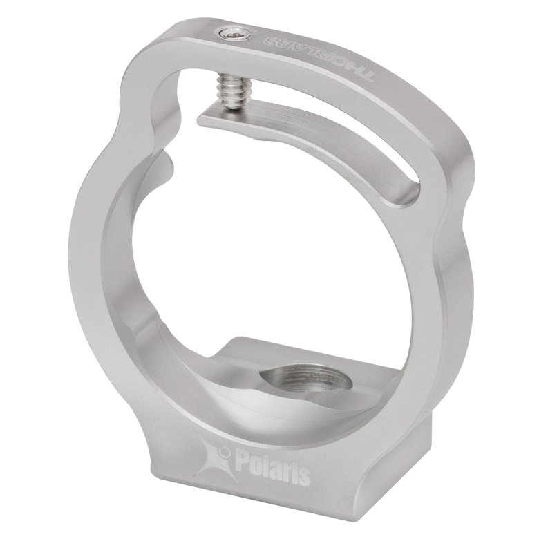 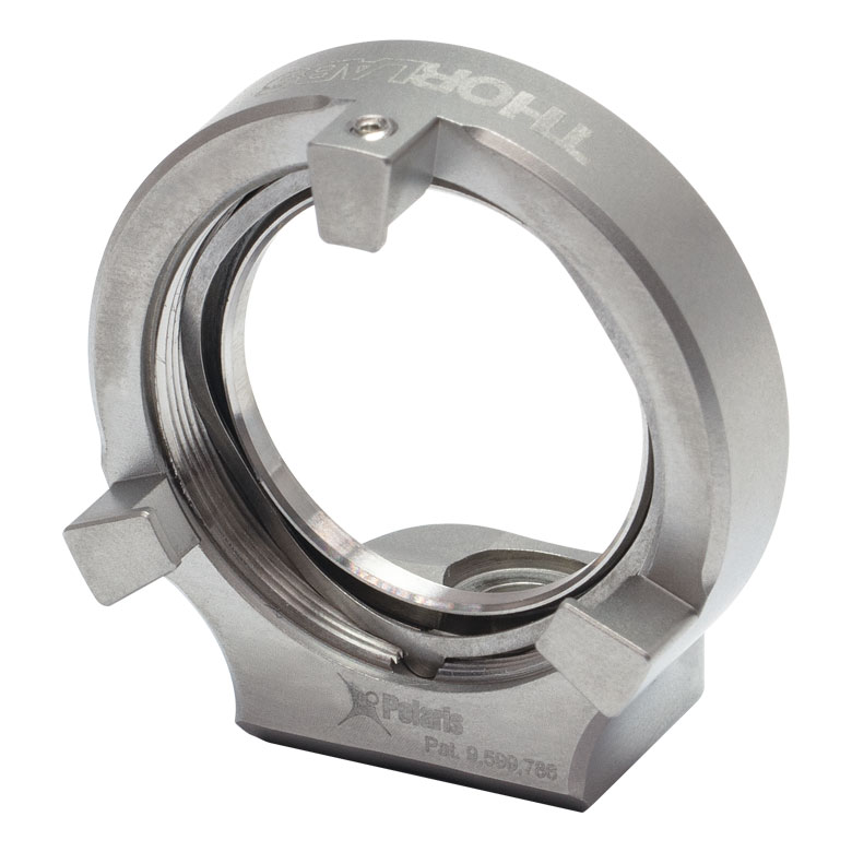 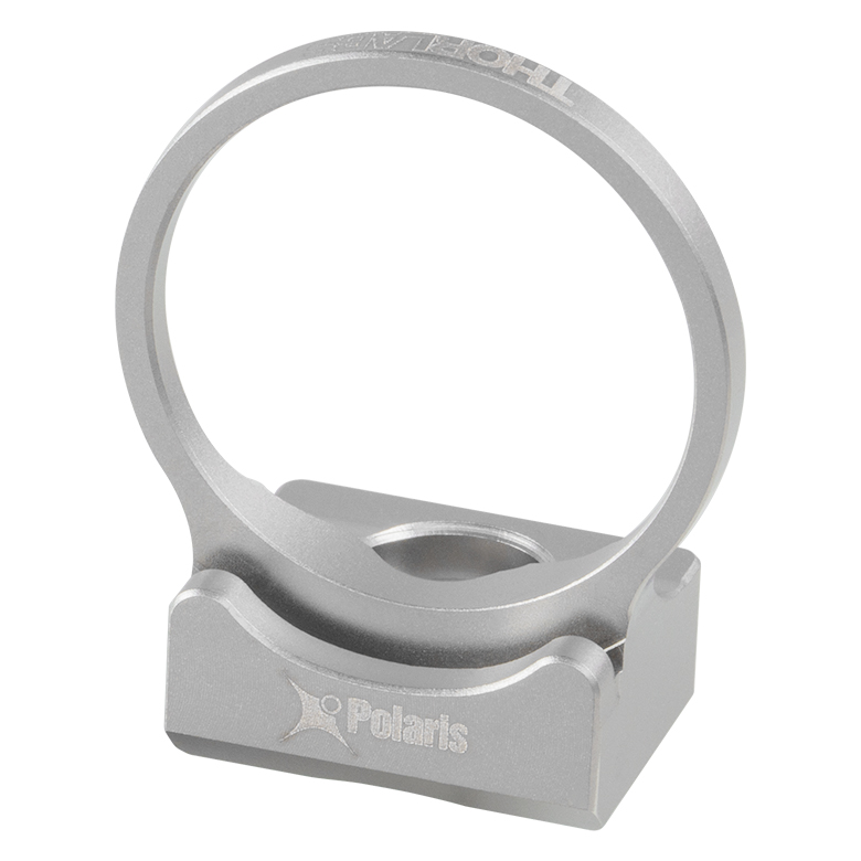  | |||||
| Optimized for Mirrors | - | -B05F | -C05G | |||
| Optimized for Beamsplitters | -B05S | - | -B05G | |||
| Optimized for Lenses | - | - | -L05G | |||
| Ø19 mm (Ø3/4") Optics | ||||||
| Optimized for Mirrors | -19S50/M | - | - | |||
| Ø1" Optics | ||||||
| Optimized for Mirrors | - | -B1F | -C1G | |||
| Optimized for Beamsplitters | -B1S | - | -B1G | |||
| Optimized for Lenses | - | - | -L1G | |||
| Ø2" Optics | ||||||
| Optimized for Mirrors | - | -B2F | -C2G | |||
| Optimized for Beamsplitters | -B2S | - | - | |||
| Table 103F Polaris Kinematic 1.8" x 1.8" Platform Mount | ||
|---|---|---|
| Optomech Retention Method | Tapped Holes & Counterbores |  |
| 2 Adjuster Knobs | -K1M4(/M) | |
| Table 103G Accessories for Polaris Mounts | |
|---|---|
| Description | Representative Photos |
| Ø1/2" Posts for Polaris Mounts |  |
| Ø1" Posts for Polaris Mounts | |
| Non-Bridging Clamping Arms | 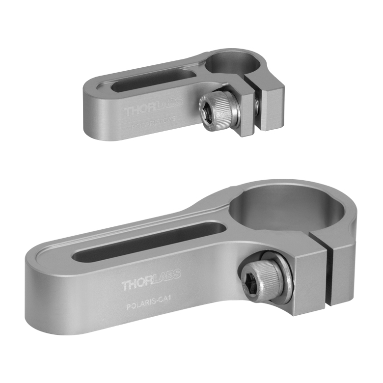 |
| 45° Mounting Adapter | 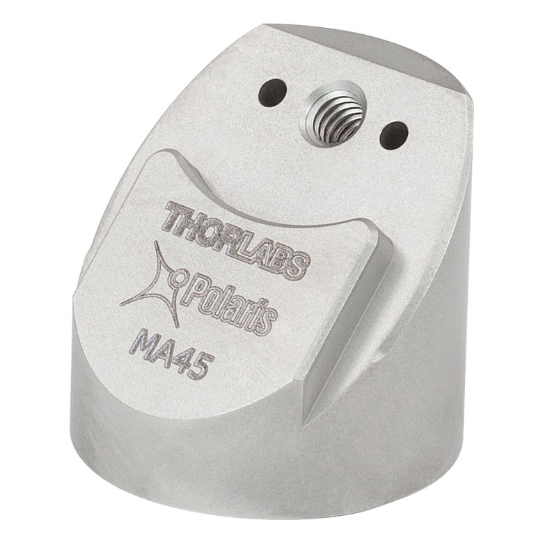 |
| Posted Comments: | |
| No Comments Posted |
| Item # | Alignment Wavelengtha |
AR Coating |
Full-Angle Beam Divergenceb | Focal Lengthc | NA | Connectors | Adjuster Drive | Adjuster Pitch |
|---|---|---|---|---|---|---|---|---|
| PF2F53(/M) | 532 nm | Ravg < 0.5%, 350 - 700 nm |
0.02° | 10.90 mm | 0.25 | FC/PC, Three 2.2 mm Wide Key Slotsd |
5/64" (2.0 mm) Hex, Ø0.07" (Ø1.8 mm) Side Adjustment Holes | 3/16"-130 Matched Actuator/Body Pairs |
| PF2F63(/M) | 633 nm | Ravg < 0.5%e, 650 - 1050 nm |
0.022° | 10.99 mm | ||||
| PF2F78(/M) | 780 nm | Ravg < 0.5%, 650 - 1050 nm |
0.026° | 11.07 mm | 0.26 | |||
| PF2F85(/M) | 850 nm | 0.03° | 11.12 mm | 0.25 |

 ズーム
ズームVideo 633B クロススレッド(斜めにねじ込む状態)しないように止めナットを取り付けるには、まずアジャスタの先に止めナットをそっと置いてください。止めナットを少々緩める方向に回し、止めナットのネジ部分とアジャスタのネジ部分を合わせてからアジャスタに締め付けてください。 動画では止めナットPOLARIS-LN1を低歪みマウントPOLARIS-K1F1に取り付ける方法をご紹介しています。
Click to Enlarge
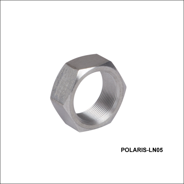
Figure 633A マウントPOLARIS-K19S4に取り付けた止めナットPOLARIS-LN05
- アジャスタの長期安定性を保つ止めナット
- Polarisマウントに対応(一部使用できない製品あり)
こちらの止めナットは、3/16”-130アジャスタ付きのPolarisマウントとお使いいただく設計です。アジャスタの長期安定性、または衝撃や振動にさらされる用途向けに設計されており、Polaris同様、あらかじめ高真空対応のアウトガスの少ないPTFEグリースが塗布されており、またアジャスタとの適合性が試験されています。
アジャスタをたびたび調整しなければならない場合には、止めナットは手でおよそ0.03~0.06 N·mのトルクで軽く締め付けるだけで十分です。長期安定性を必要とする場合には、締め付けトルクとして0.17 N·mを推奨していますが、このトルクは当社のプリセット型トルクレンチTW6(下記参照)をご使用いただくと得ることができます。止めナットPOLARIS-LN05を締め付けるには6 mmのレンチが必要です。止めナットを取り付ける時にクロススレッド(斜めにねじ込む状態)しないように、まず止めナットをアジャスタ部分に置き、次に止めナットがアジャスタのネジに整合するまで緩める方向に回し、その後でアジャスタに締め込むようにしてください。

 ズーム
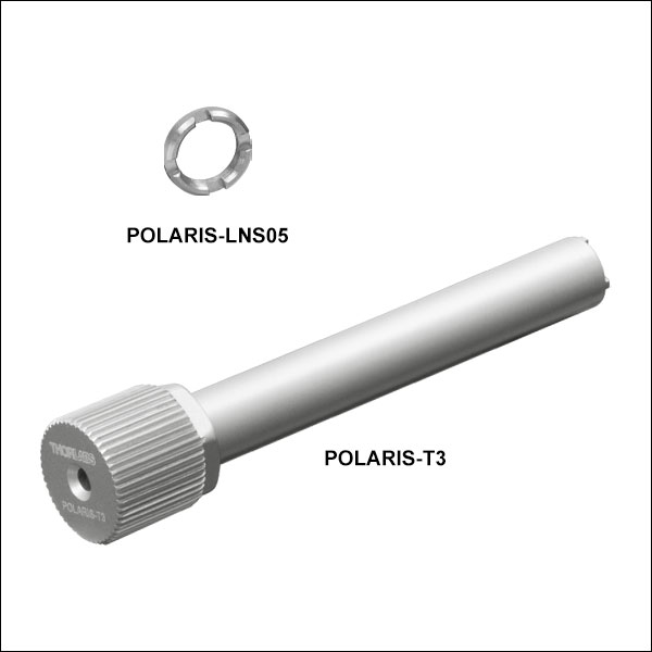
ズーム- アジャスタの長期安定性を保持
- Polarisマウントに対応(一部使用できない製品あり)
- 薄型:Ø6.4 mm x 1.3 mm(厚さ)
- スパナレンチPOLARIS-T3を使用して回転軸に沿った締め付けが可能
ロック用カラーPOLARIS-LNS05 は、3/16"-130アジャスタの付いたPolarisマウントにご使用いただけます。ただし、ピエゾ駆動のマウントや低頭アジャスタのマウント(型番POLARIS-K05とPOLARIS-K05S1)には対応しておりません。このロック用カラーは、アジャスタに長期安定性を求める用途や、衝撃・振動にさらされる用途向けに設計されています。また、Polarisマウントと同様にあらかじめ高真空対応のアウトガスの少ないPTFEグリースが塗布されており、アジャスタとの整合性も試験されています。
スパナレンチPOLARIS-T3は、ロック用カラーPOLARIS-LNS05の固定用に特化して設計されています。ダブルスパナヘッドのため嵌合性に優れ、またロック用カラーをアジャスタの軸に合わせて調整することができます。スパナレンチの中心の貫通穴から2 mmボール(六角)ドライバを挿入できるため、ロック用カラーを締める際にアジャスタの位置を固定しておくことができます。
アジャスタをたびたび調整するような場合には、ロック用カラーは0.03~0.06 N·m程度のトルクで軽く締めれば十分です。 長期安定性を必要とする場合には、締め付けトルクとして0.23 N·mを推奨しています。 このトルクは、当社のプリセット型トルクレンチTW13(下記参照)とスパナレンチPOLARIS-T3を組み合わせてご使用いただくと得ることができます。ロック用カラー締付け時のクロススレッド(斜めにねじ込む状態)を防ぐために、カラーをアジャスタにセットしたら、まずカラーをアジャスタのネジの小さな段差を感じるまで緩める方向に回し、その後でアジャスタにねじ込んでください。
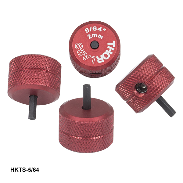
つまみネジ型六角レンチ")
 ズーム
ズーム
- 2 mm(5/64インチ)の六角レンチを使用するアクチュエータの調整に便利
- 赤色アルマイト加工の調整ノブで六角レンチのサイズが刻印
- 六角チップは取り替え可能
- 1パック4個入り
この2 mm(5/64インチ)六角レンチ型の調整用つまみネジを使用することで、2 mm六角レンチで調整するアクチュエータ(またはノブを取り外した標準タイプのアクチュエータ)が迅速に調整できます。 これは取り外し可能なノブであるため、調整の合間にネジの六角穴に取り付けたままにしておくことができて便利です(Figure 206A参照)。 #8-32止めネジ(2 mm六角)が取り替え可能の六角形のビットを固定します。この取り替え可能なビットは、一方の先端がつぶれてしまっても、逆向きで再利用できます。 交換用の六角レンチ型ビットが必要な場合には、当社にお問い合わせください。
つまみネジ型六角レンチには、0.050~3/16インチと2 mm~5 mmのサイズの製品があります。

 ズーム
ズーム
Click to Enlarge
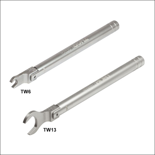
Figure 676A 各レンチには型番とプリセットされたトルク値が刻印されています。
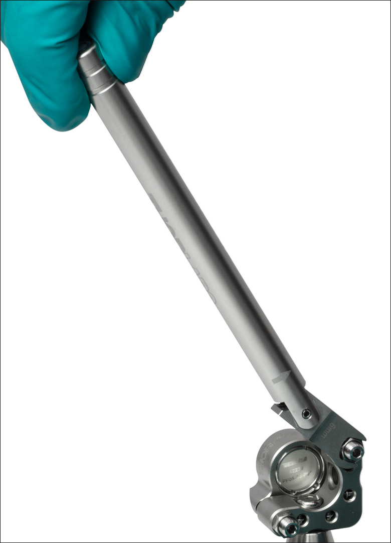
Click for Details
Figure 676B トルクレンチTW6を使用して、ミラーマウントPOLARIS-K05T2に止めナットPOLARIS-LN05を固定
- Polaris止めナットとスパナレンチ用のプリセットトルクレンチ(対応する製品についてはTable 676Cをご覧ください)
- TW6: 6 mm六角、0.17 N•m
- TW13: 13 mm六角、0.23 N•m
- 適切なトルクを確実に負荷できるブレークオーバー(Break-Over)型
- 長期的に固定する用途に適しています。
こちらのトルクレンチには、Polarisマウントの止めナットを長期的に固定するうえで適切なトルク値がプリセットされています。仕様についてはTable 676Cをご覧ください。プリセットされたトルク値に達すると、Figure 676Bのようにピボットジョイントが折れ曲がる仕組みになっています。力を抜くと、レンチの六角ヘッドは元の位置に戻ります。この設計により、止めナットに設定値以上のトルクが加わるのを防止しています。指標として刻印されている線は、定められたトルクをかけるためにレンチを回転させる角度を示しています。この線を越えてハンドルを回転させると、止めナットを締め付けすぎていることになります。レンチには、使用時に識別しやすいように、プリセットのトルク値、トルクをかける方向、レンチサイズ、および型番が刻印されています。
これらのレンチは、クリーンルームや真空チャンバ内でも使用可能です。すべてCarpenter AAA不動態化処理による化学洗浄を行い、表面から硫黄、鉄、汚染物質などを除去しています。不動態化処理の後は、クリーンな(汚染されていない)環境下で組み立て、2重の真空バッグに入れてクリーンルームに搬入するまでの間に汚染されないようにしています。レンチはビードブラスト加工されているため、レーザを使用するセットアップで作業するときでも反射光が最小限に抑えられます。
なお、こちらのレンチはアジャスタを高頻度で調整するためのものではありません(そのような用途で必要とされるトルク値は、通常0.03~0.06 N•mです)。
| Table 676C Specifications | ||||
|---|---|---|---|---|
| Item # | Hex | Torque | Torque Accuracy | Compatible Items |
| TW6 | 6 mm | 24 oz-in (0.17 N•m) | ±1.44 oz-in (0.010 N•m) | LN19100H 3/16"-100 Aluminum Lock Nut, POLARIS-LN05 3/16"-130 Stainless Steel Lock Nut |
| TW13 | 13 mm | 32 oz-in (0.23 N•m) | ±1.92 oz-in (0.014 N•m) | POLARIS-LN1 1/4"-100 Stainless Steel Lock Nut POLARIS-LN4 3/8"-100 Stainless Steel Lock Nut POLARIS-T2 Spanner Wrench for POLARIS-LNS1 Locking Collar POLARIS-T3 Spanner Wrench for POLARIS-LNS05 Locking Collar |