FiberPortコリメーター/カプラー

- Ultrastable Micropositioning Alignment with Five Degrees of Freedom Plus Rotation Adjustment
- Usable with Single Mode, Multimode, and Polarization-Maintaining Fiber
- Aspheric or Achromatic Lens
- Models Available for 350 nm - 5 µm
PAF2P-11E
Aspheric FiberPort,
FC/PC, 2.0 - 5.0 µm AR Coating
PAF2-A4C
Achromatic FiberPort,
FC/PC and FC/APC,
1050 - 1620 nm AR Coating
PAF2S-11A
Aspheric FiberPort,
SMA, 350 - 700 nm AR Coating
Back
Front

Please Wait
| FiberPort Quick Links | |||
|---|---|---|---|
| Item # | Lens Type | Connector | EFLs (mm) |
| PAF2-Ax | Cemented Achromatic Doublet | FC/PC & FC/APC | 4, 7.5 |
| PAF2P-Ax | FC/PC | 10, 15 | |
| PAF2A-Ax | FC/APC | 10, 15 | |
| PAF2S-Ax | SMA | 4, 7.5 | |
| PAF2-x | Molded Aspheric Lens | FC/PC & FC/APC | 2, 4, 4.6, 7.5 |
| PAF2P-x | FC/PC | 11, 15.3, 18.4 | |
| PAF2A-x | FC/APC | 2, 4.6, 7.5, 11, 15.3, 18.4 | |
| PAF2S-x | SMA | 2, 4.6, 7.5, 11, 15.3, 18.4 | |
特長
- 5自由度の調整とファイバ回転調整が可能
- 低ヒステリシス(詳細は「グラフ」タブ参照.)
- FC/PC、FC/APCならびにSMAタイプ
- 非球面レンズまたはアクロマティックレンズ付き
- シングルモード、マルチモード、および偏波保持ファイバに適した製品
- 可視、近赤外、または中赤外域用のARコーティング付きをご用意(詳細は「セレクションガイド」タブ参照)
当社の小型で安定性が高いFiberPortマイクロポジショナは、光ファイバとの光結合(入射および出射)用として使いやすいプラットフォームです。コンパクトなサイズ、再現性の高い高分解能なアライメント機構、高い熱安定性、および固定機構(詳細は「取扱い」タブ参照)といった特長により、このFiberPortはファイバとの結合およびコリメート用として短期用にも長期用にも適しています。各FiberPortは、下記の赤いアイコン (![]() ) をクリックするとご覧いただける図面に記載された波長でコリメートされるよう、出荷前にアライメントされています。ヒステリシスならびに熱安定性については「グラフ」タブをご覧ください。
) をクリックするとご覧いただける図面に記載された波長でコリメートされるよう、出荷前にアライメントされています。ヒステリシスならびに熱安定性については「グラフ」タブをご覧ください。
各FiberPortには、焦点距離が2.0 mm~18.4 mmのアクロマティックレンズまたは非球面レンズが取り付けられています。FC/PC、FC/APCまたはSMAファイバーバルクヘッド付きの製品をご用意しております。有効焦点距離が短い(≤7.5 mm)FiberPortとして、FC/PCならびにFC/APCコネクタ両方にご使用いただけるFCバルクヘッド付きのFiberPortがございます。5軸調整機能に短い焦点距離を組み合わせた場合、軸外への出射光は無視できるレベルに調整可能です。FiberPortの選択について詳細は「セレクションガイド」タブをご覧ください。
FiberPortを用いて光結合やコリメートを行う際、結合効率を高めるために当社のARコーティング付きファイバーパッチケーブル (シングルモード、マルチモードまたは偏波保持)のご使用をお勧めいたします。これらのパッチケーブルは高出力光源からの光の後方反射を低減します。中赤外域で使用するFiberPortには、当社のフッ化物ファイバーパッチケーブルをお勧めいたします。
アクロマティックFiberPort
当社のアクロマティックFiberPortは、非常に小さな焦点距離の変化で広い波長領域にわたって光をコリメートします。そのため、光源の波長が変わった場合も再調整の必要が低減されます。アクロマティックFiberPortと、類似する非球面FiberPortの両方の焦点距離の変化は上記「セレクションガイド」タブからご覧いただけます。こちらのFiberPortは、有効焦点距離 4.5 m、 7.5 mm、10 mmまたは15 mmでご用意しております。各アクロマティックFiberPortの有効焦点シフトは、下の表でご覧いただけます。アクロマティックレンズの性能について詳細はこちらをご覧ください。
5自由度の調整(およびバルクヘッド回転調整)
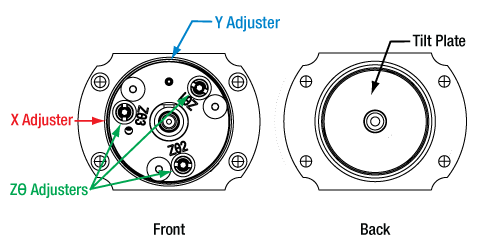
コネクタとファイバを固定したまま、内蔵されたレンズのアライメント調整を5つの自由度で行うことできます。5つの自由度とは、XY方向の直線移動調整、あおり調整(チップ&チルト)、およびチップ&チルト調整用ネジを同時に動かすことによるZ方向の調整を意味します。非球面レンズのXY方向の移動範囲は±0.7 mmで、分解能は1回転につき317 µmです。Z方向の移動範囲は±1.0 mmで、分解能は 1回転につき200 µmです。これに加え、前面プレートの皿ネジ3個を緩めて、偏波保持ファイバのアライメントのためにバルクヘッドを回転調整することもできます。アライメント終了後は、筐体側面にある固定用止めネジを締め付けてXYの位置を固定できます。また、Zθアジャスタの固定用カラーを使用してチップ&チルトの位置も固定できます。FiberPortの操作方法の詳細については「取扱い」タブをご覧ください。 バルクヘッドの調整に関する細かい手順等については当社までご連絡ください。
取付けオプション
FiberPortには当社のFiberBenchアクセサリに対応する#2ザグリ穴が4つ付いています。当社ではFiberPortをØ12 mm~Ø12.7 mm(Ø1/2インチ)ポストや30 mmケージシステム、さらにHeNeレーザに使用できるアダプタも開発しました。詳細については「FiberPortの取付け」タブをご覧ください。
付属ハードウェア
FiberPortにはダストキャップ、0-80固定用ネジ、0.028インチ六角レンチ(固定ネジ用)、0.050インチ六角レンチ(Zθ、X、Yのアジャスタ用)、およびスパナレンチSPW403(Zθアジャスタの固定用カラー締め付け用)が付属します。
SM1外ネジ
当社の多くのオプトメカニクス部品と組み合わせられるように、FiberPort本体にSM1外ネジを追加しました。固定用カラー
Zθアジャスタの固定用カラーは、付属のスパナレンチを使用し、アライメント位置を固定します。このカラーは、シングルモードファイバのアライメントにも影響を与えることなく固定できます。 またZθアジャスターネジが移動しすぎるのを防ぎます。熱膨張係数(CTE)の整合
使用されている材料の熱膨張係数(CTE)を一致させることにより、最適な熱的性能が得られています。また、安定性向上のため、レンズセルとティルトプレートは硬化処理されたステンレススチール製になっています。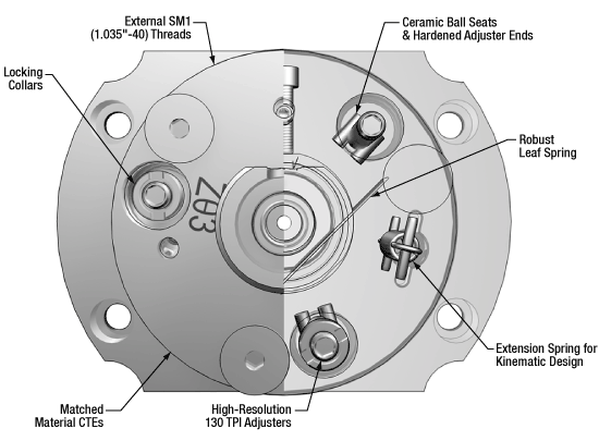
FiberPortの特長:外部(左)と内部(右)
セラミックボールシート&高硬度のアジャスタ先端
長寿命のセラミックボールシートと高硬度のアジャスタ先端を採用し、しっかりした嵌合と熱的安定性を実現しています。頑丈な板バネ
新しい板バネの形状により曲げ板バネとなるリスクが低減されるため、ヒステリシスを最小限に抑えながら再現性の高い、また一貫性のあるX-Y移動が実現できます。キネマティック設計
引っ張りバネは、当社のキネマティックマウントの支点とバネを用いた設計に基づいているため、調整の再現性が高く、一貫性があります。130 TPIアジャスタ
アジャスタの分解能が高いほど、ティルトプレートのより微細な移動が可能になります。追加情報
詳細については下の枠をクリックしてください。
こちらのFiberPortは、特に光学系における典型的なミスアライメント誤差、すなわち温度変化によって発生するヒステリシスならびにクロストークを低減するように設計されています。広範囲にわたる研究、先進の設計ツールを用いた様々な設計検証や何か月にも渡る厳格なテストの結果に基づいて部品を選定し、FiberPortの極めて高い安定性を実現しました。詳細については「グラフ」タブをご参照下さい。
多くの研究室では温度が変動するため、アライメントに敏感な光学系に用いるすべてのマウントは、熱によるミスアライメントが最小となるようにしなければなりません。このミスアライメントを最小限に抑えるため、FiberPortを構成する部材には熱膨張係数が小さいステンレススチールが選ばれました。また、レンズセルとティルトプレートは、さらに耐久性を増すよう硬化処理されたステンレススチール製になっています。
位置のドリフトとバックラッシュを最小限に抑えるためには、アジャスタのあそびと潤滑剤の量を制限する必要があります。アクチュエータの調整を行ったとき、潤滑剤は動いてどこかに蓄積します。この非平衡状態にある潤滑剤はゆっくりと平衡状態に戻っていきます。しかし、このプロセスでティルトプレートが移動する場合があります。このFiberPortでは、工業規格よりも厳しい基準で本体と整合性のあるアジャスタを採用しているため、アジャスタの潤滑剤はほんのわずかしか必要ありません。その結果、FiberPortのアライメントは調整後でも極めて安定しています。また、アジャスタは滑らかに動かすことができるので、繰り返し細かい調整を行なうことができます。
こちらのFiberPortでは従来よりも長い板バネを採用しているため、曲げバネとなるリスクが小さくなります。またレンズセルに対する反力により正確に対応するため、レンズセルのX-Y方向への移動は全移動範囲にわたりより予測しやすくなります。
ZまたはZθ方向の調整には分解能の高い130 TPIアジャスタを採用しているため、より微細な移動が可能です。また、これらのアジャスタによる移動にはリミッタがかかるようになったため、レンズセルがX-Yアジャスタから外れるまで移動するのを防止します。
クロストークは、寸法公差、部材の性質、および部品の仕上げを慎重に制御することで最小限に抑えられています。標準的なアクチュエータの金属-金属の接触点は、時間がたつにつれて摩耗します。これを防ぐために、ティルトプレートとアクチュエータ間の3か所のすべての接触点にセラミックシートが使用されています。これらのセラミックシートと、硬化処理されたステンレススチール製のアクチュエーターチップを組み合わせて使用することで、時間が経過しても接触面の整合性が保たれます。
多くの研究室で使用する際は必要ありませんが、レンズセルとティルトプレートは固定することができます。レンズの固定は付属の固定ネジを使用します。ティルトプレートの位置は、Zθ用の固定カラーを締め付けることで固定できます。これによりアジャスタの回転は防止され、ティルトプレートは動かなくなります。これらのロック用カラーを使用しても、シングルモードファイバのアライメントは維持されます。
当社の標準的なキネマティックマウントは、支点とバネ、およびボールベアリングを使用して調整するように設計されています。これにより一貫性と再現性の高い移動が可能となります。FiberPortも同様に構築されています。ティルトプレートを動かすには引張りバネを使用し、また頑丈なボールシートとアジャスタ先端ボールを用いています。
FiberPortの外周にはSM1ネジが付いており、SM1レンズチューブや様々な固定マウントを含む当社の多くのオプトメカニクス部品に取り付けることができます。必要なときには、SM1ネジ付き固定リングを用いて、FiberPortをこれらの部品に固定することができます。

Click to Enlarge
FiberPortの内部構造、外部筐体を付けた状態と外した状態
XY調整
| Specifications | |
|---|---|
| Screw Size | 0-80 |
| Hex Size | 0.05" (1.3 mm) |
| Adjustment per Revolution | 317 µm |
| Translation Range | ±0.7 mm |
磁気レンズセルは、FiberPort本体側面の六角穴付きキャップスクリュ(上の写真の赤と青の表示)を用いて、チルトプレートとは独立してXY方向に移動できます。各アジャスタは簡単に識別できるようX、Yと表示されています。レンズのXY方向への移動範囲は±0.7 mmです。XとYのアジャスターネジの仕様については上の表をご覧ください。なおFiberPortを標準的なコリメート用または結合用として使用する場合は、移動範囲はわずかしか必要ありません。
XY方向の移動は、角度およびZ軸調整とは独立しています。レンズセルはチルトプレートに磁石で付いており、アジャスタに対する反力は板バネで生成されています。これらのネジを調整するときの抵抗力は、下記のXY抵抗力アジャスタにより変更できます。各アジャスタと対応する抵抗力アジャスタは同じ色で色付けされています。XY方向の移動は下記の固定ネジで固定できます。
Zθ調整
| Specifications | |
|---|---|
| Screw Size | M2 x 0.2 |
| Hex Size | 0.05" (1.3 mm) |
| Adjustment per Revolution | 200 µm |
| Translation Range | ±1.0 mm |
各FiberPortを構成するレンズセルは、磁石でチルトプレートに付いています。このチルトプレートは上の写真の緑色で示されている3つのZθアジャスタで動きます。各アジャスタにはZθ1、Zθ2、Zθ3の表示があり、どのアジャスタが既に調整済みで、これからどのアジャスタを調整すべきなのかが判別しやすくなっています。各アジャスタを同じ増分量だけ回すと、FiberPortの光軸に沿ってZ軸方向に移動します。Z軸の移動範囲は±1.0 mmです。Zθアジャスターネジの仕様については上の表をご覧ください。
最終的な調整を行った後、チルトプレートの位置は付属の固定用カラーとスパナレンチSPW403を用いて固定できます。これらのアジャスタはシングルモードファイバのアライメントを維持したまま固定することが可能です。
チルトプレートの移動の仕組みは、当社のキネマティックマウントの支点とバネを用いた仕組みと非常に良く似ています。各アジャスタには、セラミック製のボールシートに納まる硬化スチール製のボールエンドが付いています。ボールエンドとセラミック製シートはどちらも高温でアウトガスの少ない接着剤を用いて取り付けられているため、安定的に長期間使用可能なキネマティックシステムとなっています。引っ張りバネは、微調整ネジに対する反力を生成しています。
XY位置の固定
| Specifications | |
|---|---|
| Screw Size | 0-80 |
| Hex Size | 0.05" (1.3 mm) |
FiberPortの底面にある止めネジ(セットスクリュ)を用いて、XYアジャスターネジの位置を保持することができます。ほとんどの用途ではFiberPortを固定する必要はありません。例えば、FiberPortが振動の少ない環境に置かれている場合は、固定ネジによる固定は必要ありません。
しかし、FiberPortを出荷するときなど、大きな振動や衝撃を受ける可能性がある場合には、ネジで固定するようにしてください。固定ネジを使用すると、結合に影響を及ぼす場合があります。固定する場合には、FiberPortマニュアルに記載されているすべての適用すべき指示に従ってください。固定ネジは付属品ですが、FiberPort出荷時には取り付けられていませんのでご注意ください。
XY移動に対する抵抗力
| Specifications | |
|---|---|
| Screw Size | 0-80 |
| Hex Size | 0.028" (0.7 mm) |
XYアジャスタを動かすときの抵抗力は、FiberPort面に付いている各XYアジャスタに対応するネジによって調整可能です。アジャスタに対する抵抗力を大きくすると、設定したい位置を行き過ぎることなく、MLCの微調整を容易に行うことができます。逆に抵抗力を小さくすれば、過度な力をかけることなく大きな位置の移動を容易に行うことができます。
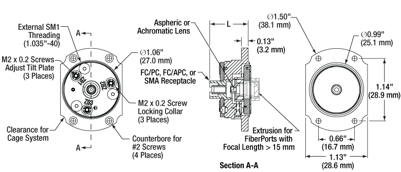
上の図面のLは、FiberPort前面から取付けフランジまでの寸法のうち、コネクターバルクヘッドを差し引いた寸法です。この値は焦点距離とコネクターバルクヘッドに依存します。各FiberPortの正確な長さについては下の表をご覧ください。
ARコーティング
Click to Enlarge
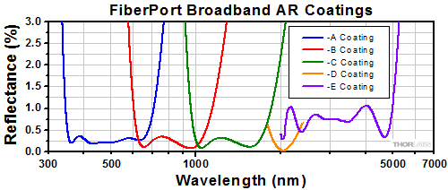
各FiberPortのレンズには、-A (350~700 nmまたは400~700 nm)、-B (600~1050 nmまたは650~1050 nm)、-C (1050~1620または1050~1700 nm)、-D (1.8~2.4 µm)、-E (2.0 - 5.0 µm)のコーティングが施されています。
熱安定性
FiberPortの熱安定性は、環境温度を±10 °C変化させ、温度に伴う結合効率の変動を測定して評価しました。FiberBench FB-38にPAF2P-11Aを取り付けて測定しました。635 nm光源とシングルモードファイバを使用しました。 なお熱安定性は部品とシステムのセットアップに大きく依存しますのでご留意ください。
結果:
約5%の結合効率の変動は、このFiberBench/FiberPortシステム内のすべての部品の動きの結果です。この変動はビームスポットがファイバーコアに対して約0.5 µm移動したことに対応します。温度を変化させた後、最初の温度に戻したときの結合効率は、初期値の1%以内に戻っています。
軸調整の再現性
Zθ調整の再現性は、Zθアジャスタを200~300 µrad移動させ、(0、0)の初期位置に戻すことで測定しました。測定は3回実施しました。ビームの動きを測定するために、FiberPortから出射されるビームをCCDビームプロファイラで受けています。 測定にはPAF2P-11Aを使用し、ビームの波長は635 nmでした。
結果:
右のグラフのとおり、FiberPortは良い再現性を示し、ヒステリシスも小さいことが分かります。これらは典型値で、選択する波長とFiberPortの焦点距離によって変わります。
はじめに
FiberPortを選択する前に、下記を考慮する必要があります。
- 光源の波長
- ファイバの種類(シングルモード、マルチモード、または偏波保持)
- ファイバーコネクタ(FC/PC、FC/APCまたはSMA)
- 必要とされるレンズの種類(アクロマティックまたは非球面レンズ)
これらの情報により、お客様のシステム構成に最も適したFiberPortを見つけ出すことが可能です。以下に記載するのは、光結合用のFiberPortを探すのに適した方法です。この例では結合するファイバとしてシングルモードファイバを想定しています。 シングルモードの場合は、FiberPortとファイバの適合性を判断するのに必要な計算がマルチモードよりも複雑で、主にファイバとレンズのNAを考慮する必要があります。
右のボタンをクリックすると、光結合に最も適したFiberPortの選択作業を支援する、マクロ有効のエクセルファイルをダウンロードいただけます。ご質問などございましたら当社までご連絡ください。
有効焦点距離の計算方法
例:
- 波長:633 nm
- ファイバ:P1-630A-FC-2
- レンズに入射するコリメートビーム径:Ø3 mm
FC/PCシングルモードパッチケーブルP1-630A-FC-2の仕様から、波長が633 nmの時の1/e2モードフィールド径(MFD)は4.3 μmです。このMFDは、下記の式で計算される回折限界スポットサイズØspotと等しくなければいけません。

ここで、fはレンズの焦点距離、λは入射光の波長、Dはレンズに入射するコリメートビームの1/e2径です。これによりコリメートレンズの焦点距離は以下のように得られます。

当社は、様々なFiberPortを豊富に取り揃えています。ファイバーコネクタもARコーティング範囲の条件も合致するFiberPortの中で、16 mmに最も近い15.3 mmの焦点距離を持つ製品にFiberPort(型番PAF2P-15A)があります。また、このFiberPortの開口は、コリメートされたビーム径よりも大きくなっています。よって、これが与えられた初期パラメータ(つまり、シングルモードファイバP1-630A-FC-2、Ø3 mmのコリメートされたビーム径)に対して最も適した選択となります。
光結合を最適化するには、集光ビームのスポットサイズをシングルモードファイバのモードフィールド径より小さくしなければなりません。そのため、もし完全に整合するFiberPortがない場合には、上記の計算式で算出された値より短い焦点距離を持つFiberPortを選択してください。あるいは、レンズの開口が十分大きい場合は、ビームをレンズの前で拡大することで、集光ビームのスポットサイズを小さくすることができます。
下の仕様表に記載されたNAの値はレンズの開口数を示しており、使用するファイバに要求される開口数ではありませんのでご注意ください。なお、コリメートされたビーム径がレンズの開口よりも小さい場合は、ビーム径を用いてNAを再計算する必要があります。FiberPortを選択する際に最良の結果を得るには、上記の計算式か、右上のリンクのCalculatorを使用することをお勧めいたします。
レンズの選択
FiberPortを選択する際には、FiberPortに取り付けられているレンズがお客様のセットアップに対応していることを確認することが重要です。特に、レーザ光源の波長がレンズのARコーティングの範囲内にあり、スポット径と焦点移動がシステムに対して有益な作用を及ぼす必要があります。
ARコーティング
当社のFiberPort内のレンズには、-A (350~700 nmまたは400~700 nm)、-B (600~1050 nmまたは650~1050 nm)、-C (1050~1620または1050~1700 nm)、-D (1800~2400 µm)、-E (2000 - 5000 nm)のARコーティングが施されています。右のグラフは各ARコーティングの1表面当たりの反射率(典型値)を示しています。ARコーティング付きのレンズはそれぞれFC/PC、FC/APCまたはSMAコネクタ付きファイバに対応するFiberPortパッケージに納められています。FiberPortを選択する際は、ファイバ/コネクタ/FiberPortの正しい組み合わせを選択するよう注意してください。ARコーティングの情報と各FiberPortに対応するコネクタの情報は下記をご覧ください。ご質問などがございましたら当社までご連絡ください。
注:Cコーティングの波長範囲の仕様は、1050~1620 nmから1050~1700 nmに改定されています。現在取り扱っているCコーティング付き光学素子には、全て改定後の仕様(1050~1700 nm)が適用されています。ドキュメント類の更新作業をすすめておりますが、光学素子によっては、旧仕様の波長範囲が記載されたままになっている場合があります。
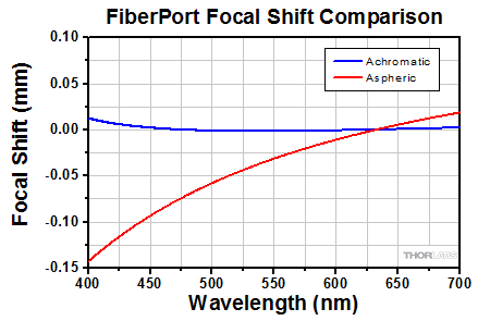
非球面FiberPortとアクロマティックFiberPortの性能比較
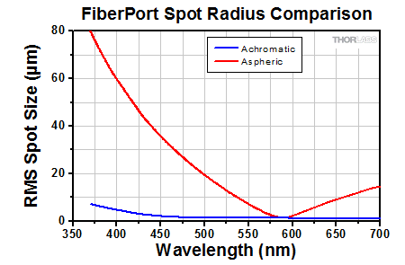
当社のアクロマティックFiberPortは、色収差を最小に抑えるよう接着された複レンズを使用しているため、広帯域のコリメート光源や多波長光源に適しています。アクロマティック複レンズによって焦点距離がわずかにシフトする効果があり、それによってFiberPortは広い波長域にわたって再アライメント調整をせずに使用することができます(下記参照)。
Click to Enlarge
ファイバに集光されたコリメート光について、アクロマティックFiberPortに使用されるアクロマティック複レンズの性能と、同じ有効焦点距離を持つFiberPortの非球面レンズの性能を比較しました。レンズは波長580 nmの光がファイバに集光するようにアライメントされています。与えられた波長範囲において、アクロマティック複レンズではファイバ上に集光スポットを生成しますが、非球面レンズでは色焦点移動により光軸に沿って波長に伴う一連の焦点が生成されます。ファイバの位置は非球面レンズの焦点に固定されているため、スポットサイズは波長に依存して大きく変化します。しかし波長の変化とともにファイバの位置を適切に調整することにより、この影響を最小限に抑えることはできます。
Click to Enlarge
このグラフは、左のグラフと同じセットアップにおける焦点距離のシフト量を示しています。どちらのレンズの焦点距離(F)も580 nm付近では同様です。全体的に、475 nm~655 nm(580 nm付近以外)における非球面レンズの焦点移動は、アクロマティック複レンズと比較して約1桁大きくなっています。580 nmより短い波長ではビームはFより短い距離で集光され、580 nmより長い波長ではFより長い距離で集光されます。
アライメント手順
すべてのFiberPortのレンズセルは磁石でチルトプレートに取り付けられており、そのチルトプレートの位置は2方向(X、Y)に調整できます。光軸に対するチップ/チルト角はZθアジャスタ(Zθ1、Zθ2、Zθ3と表示)で調整できます。これらのアジャスタを操作すると、チルトプレートが動きます。Z軸方向に移動させるときは、Zθアジャスタを均等に回転します。下記の調整には、低出力のアライメント用可視光レーザのご使用をお勧めします。
各セクションではご用途に応じて推奨されるFiberPortの使用方法をご紹介しています。なお、ご用途に関わらず、まずは「プリアライメント」をご一読ください。お届けするFiberPort製品は、下記の赤い資料アイコン![]() をクリックするとご覧いただける図面に記載されている特定の波長でコリメートされるように、予め設定されています。FiberPortのプリアライメント後、「FiberPortを使用したコリメート」のセクションではFiberPortをコリメータとして使用する方法をご説明し、「FiberPortを使用したファイバへの結合」のセクションではFiberPortを使用してシングルモードまたはマルチモードファイバに光を結合する方法をご説明いたします。
をクリックするとご覧いただける図面に記載されている特定の波長でコリメートされるように、予め設定されています。FiberPortのプリアライメント後、「FiberPortを使用したコリメート」のセクションではFiberPortをコリメータとして使用する方法をご説明し、「FiberPortを使用したファイバへの結合」のセクションではFiberPortを使用してシングルモードまたはマルチモードファイバに光を結合する方法をご説明いたします。
プリアライメント

Click to Enlarge
適切なアライメントを得るには、チルトプレートはビーム軸に対して垂直でなければなりません。
FiberPortを使用してコリメートまたはファイバ結合をする前に、チルトプレートがビーム軸に対して垂直になるよう、FiberPortを適切にアライメントすることが重要です。このアライメントがなされていない場合、その後のアライメント手順で注意を払っても、最適な結合効率を得ることができません。FiberPortをご購入後に調整を行った場合、あるいは異なる波長でコリメートする必要が生じた場合には、最良の性能を得るために下記の手順に従ってください。
チルトプレートの アライメント
レーザがオフの状態で、XおよびY軸の調整ネジを回し、目視でレンズがチルトプレート開口部の中央にくるように調整してください。チルトプレートがFiberPort本体の位置と一致し、ビーム軸に対して垂直になるまでZθアジャスタを反時計回りに回してください。この作業は精密さを要しますが、次のような方法で達成できます。
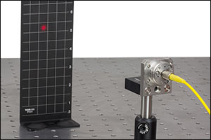
Click to Enlarge
磁石付きスクリーンTPSM1 のアライメントグリッドを使用してFiberPortのチルトプレートをアライメント
レーザ光を入力する場合(推奨)
- アライメント調整中にFiberPortが動かないようにしっかり取り付けます。
- チルトプレートが完全に移動しなくなるまでZθアジャスタを反時計回りに回します1。
- 可視のファイバーレーザを挿入します2。
- ビームを アライメント用スクリーンに向けます3。
- ビームが動き始めるまで、それぞれのZθアジャスタを時計回りに回します。ビームが動き始めたとき、アジャスタはチルトプレートに接触したことになります。操作を慎重に行うと、チルトプレートはFiberPort本体の位置に一致し、光軸に対して垂直になります4。
レーザを使用しない場合
- FiberPortの取り扱いに慣れている場合、あるいは2.0~5.0 µコーティングのFiberPortを使用している場合は2、感触のみでチルトプレートのアライメント調整を行うことが可能です。
- チルトプレートが完全に移動しなくなるまでZθアジャスタを反時計回りに回します1。
- 回転に対する抵抗が増すまで、Zθアジャスタを慎重に時計回りに回します5。
- 最初に抵抗を感じたとき、アジャスタはチルトプレートに接触したことになります。操作を慎重に行うと、チルトプレートはFiberPort本体の位置に一致し、光軸に対して垂直になります4。
一般的なQ&A
- Zθアジャスタをどこまで緩めてよいか分からない: Zθアジャスタは完全には緩めないようにしてください。またFiberPortから取り外さないでください。
- FiberPortから出射するビームが見えない: 2.0~5.0 µmコーティング付きのFiberPortは可視光を透過しません。FiberPortを右上の 「レーザを使用しない場合」に従ってアライメントすることをお勧めいたします。
- 調整によってビーム径がどのように影響を受けるのか分からない: グラデーションの小さいアライメントスクリーンを使用するとビーム径の変化が良く分かります。
- ビームの形状がよく分からない: Zθ アジャスタはほぼ完全に緩められている状態のため、FiberPortから出射されるビームは発散しています。そのためスクリーンを光源からより下流側に設置すると変化が分かりやすくなります。また、使用するアライメントスクリーンのグラデーションがビームサイズに適していることをご確認ください。
- 正しく調整できたのかが分からない: 正しい位置が得られるまで数回の試行が必要な場合があります。最初の抵抗を感じたら、それ以上は動さないでください。
一般的なアライメントのセットアップ
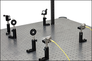
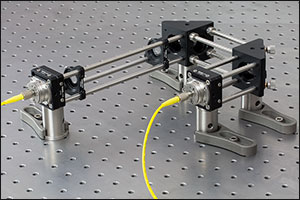
アライメント用セットアップの構成方法は複数あります。一般的なアライメント方法では、左下と中央下のように2つのミラーと2つのアイリスを使用します。それ以外に、右下のようにFiberBenchを使用すれば、2つのFiberPortを用いてシステム内に素早くかつコンパクトに組み上げることもできます。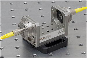
Click to Enlarge
A FiberBenchを用いると、システム内に複数のFiberPortを高い安定性で、素早く組み込むことができます。上では1軸のFiberBenchFB-51Wを使用しています。
 Click for Details
ポストを用いたアライメント用セットアップは、多くの研究室で使用されている部品で構成できます。注:このセットアップでは旧製品のルーラBHM2が使用されています。
 Click for Details
ケージシステムを用いると、すべての部品が共通の光軸に固定されるので、アライメントの手順は簡素化されます。
- ミラー、アイリス、およびFiberPortの中心が同じ光軸の中心にあることをご確認ください。当社のケージシステムまたはFiberBenchシステムを用いると、このステップは簡単になります。
- IFC/PCまたはFC/APCコネクタを使用する場合、ファイバーコネクタのキーがFiberPortと整合していることをご確認ください。偏波保持ファイバを使用する場合、FiberPortのバルクヘッドを回転させ、ファイバの偏光に合わせることができます。アライメント手順の中で、この回転の操作はできるだけ早い段階で行ってください。詳細については 「取扱い」タブをご覧ください。
- まず、ビーム光源に最も近いミラーと最も近い位置のアイリスとのアライメントを調整しますが、その際はそのアイリスの直後にレーザービュワーカードまたはアライメントターゲット を置きます。ビームスポットが消え始めるまでアイリスを徐々に閉めます。ビームの片側がクリッピングしたら、ミラーを調整してビームがアイリスの中央に来るようにしてください。 ほかのミラーとアイリスのアライメントも同じ方法で行ってください。
- ミラーとアイリスの両方のアライメントが完了するまで、2と3のステップを繰り返してください。
FiberPortを使用したコリメート
ステップ1
上記の「プリアライメント」のセクションでご説明しているようにFiberPortのプリアライメントを実施してください。ステップ2
光源の近くでのビーム径とその下流でのビーム径を測定し、コリメートの状態を確認してください1。
ステップ3
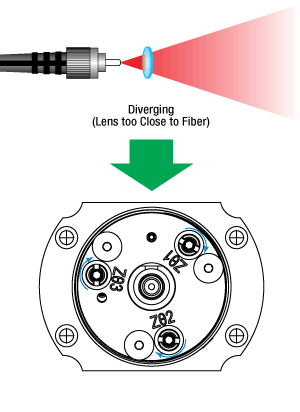
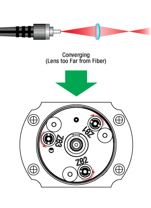
ボールドライバを使用して回転数を数えながら、Zθアジャスタを時計回りに均等に回します。レンズとビーム軸の垂直性を維持してビームの品質を保つためには、各アジャスタの回転数は同じでなければなりません。2。
ステップ4
調整を行う度に、ステップ2と同じ位置でビーム径を測定します。 ビームが収束している場合は、レンズはファイバから離れすぎています。ビームが発散している場合は、レンズはファイバに近すぎます。右の図に従ってZθアジャスタを調整してください。下流側でのビーム径が光源に近い位置でのビーム径にほぼ等しくなったとき、ビームはコリメートされています。
一般的なQ&A
- ビームがコリメートされているかどうかが分からない: 測定する位置を光源からより遠くすると、ビーム径の差が見やすくなります。
- XとYの位置は正しいように見えるが、ビームのオフセットがまだ存在する:プリアライメントが正しく行われたかご確認ください。詳細については「プリアライメント」のセクションをご覧ください。
FiberPortを使用したファイバへの結合
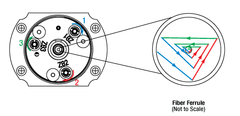 各アジャスタを同じ量だけ回転させたとき、ビームの位置は辺の長さが変化する三角形のような軌跡を描きます。光のパワーは、アジャスタを回転させた最後の位置ではなく、回転中でビームがファイバのコアに最も近いときに極大を示します。 上は結合するファイバ上のビーム位置の動きを示しています。
 原理
XとY方向への移動は、それぞれのアジャスタを使用して直接操作できますが、Z方向への移動は、3つのZθアジャスタを使用してチップ&チルト調整が必要です。そのため、アジャスタを回転させたときのビーム経路の変化は、直感的には分かりにくいかもしれません。Zθアジャスタをそれぞれ同量だけ回転させると、ビームスポットは右の図のようにファイバーコアの周りに三角形のような軌跡を描きます。測定可能な出力が得られたら、典型的なアライメント方法としては、まず出力が極大となるようネジを回し、その後さらに回し続けて極大値を僅かに超えた値にします(極大値の約95%)。この操作を各アジャスタに対して行い、次の調整でも同じ順番でアジャスタを調整していきます1。この方法では、光出力が極大値に留まってしまうのを避けられます。各過程において得られる極大値は、レンズ-ファイバの間隔が最適化 (スポットサイズは最小化) されるまで増加し、最大値に到達するまで続けます。この方法では、ビームは1回の調整ごとに長さが徐々に縮まっていく三角形のような軌跡を描く効果があります。
なお、典型的な最大結合効率はシステム構成とセットアップに大きく依存します。多くの構成では60%~80%の結合効率が得られます。この結合効率は、すべてのシステム部品の精密なアライメントと、全ての部品の整合性を検証することで向上させることが可能です。50%を下回る結合効率の場合は、部品の著しい不整合、あるいはミスアライメントの可能性があります。
ステップ3
調整を行うアジャスタの順番を決めたら、その順番を守ってください1。各Zθアジャスタを出力が極大になるように時計回りに回し、さらに回し続けて極大値を僅かに超えた値にします(極大値の約95%)。アジャスタを時計回りに回したときに出力が下がる場合は、その時の調整は行わずにスキップし、次の調整に進むことを繰り返してください。極大値が減少し始めたら回す方向を反対にし、アジャスタごとに出力が最大となるように回して、そこを行き過ぎないようにします。
ステップ2
システムに適合するマルチモードファイバをFiberPortとパワーメータに挿入します2。各位置の強度のピークを観察しながらXとYの位置をパワーが最大となるように調整してください。 最大値に到達したら、後述のシングルモードファイバを使用する場合以外は、アジャスタの位置は変更しないでください。
ステップ1
上記の「プリアライメント」のセクションで説明しているようにFiberPortのプリアライメントを実施してください。
ステップ6(オプション)
必要であれば、アジャスタは固定用カラーと付属のスパナレンチSPW403で固定できます。また、レンズセルは、FiberPort前面の4時の位置にあるネジ穴に、付属の0-80ネジを取り付けることで固定可能です。
シングルモードファイバのみ
ステップ5
ステップ3を繰り返します。システムはより敏感になるため、より細かい調整が必要になります。どのネジをどちらの方向に回しても出力が下がる場合は、ビームスポットがファイバのコア中心にあったとしても集光が不適切な場合があります。各アジャスタを少しずつ(1/16回転)同じ方向に回し、その後各Zθアジャスタごとに出力を極大にしてみてください。その極大値が前回よりも低い場合、各Zθアジャスタを少しだけ反対方向に回し、出力を極大にしてみてください。真の最大値が得られるまでこれを繰り返してください。
ステップ4
シングルモードファイバに結合する場合には、まずマルチモードファイバをシングルモードファイバに交換します。パワーメータで測定される強度は大幅に下がることが予想されます。
一般的なQ&A
- 回転するアジャスタの順番が分からない: 例えばZθ3、Zθ1、Zθ2の順番で調整することを選択した場合、それに続く毎回の調整ではその順番を維持してください。
- システムに適合するファイバが分からない: 詳細については「 セレクション ガイド」タブをご覧ください。
ビームの広がり角の理論的近似値
仕様表に記載されているビームの広がり角(全角)は、ファイバーコリメータについて計算された理論値です。この広がり角は、ファイバからの光がガウス型の強度プロファイルを有する場合、下記の計算式より理論的近似値を簡単に求めることができます。この計算式は、シングルモードファイバの場合にはよく当てはまりますが、非ガウス型の強度プロファイルの光を出射するマルチモードファイバからの広がり角については実際より小さい数値を与えます。
広がり角(全角、単位は°)は以下の式で求められます。

ここでMFDはモードフィールド径、fはコリメータの焦点距離です。(注:この式ではMFDとfは同じ単位を使わなければなりません)。
例:
コリメータPAF2-A4Aを460HPのようなシングルモードファイバと組みあわせ、MFD = 3.5 µm、f ≈ 4.0 mmとした場合、広がり角は以下のようになります。
θ ≈ (0.0035 mm / 4.0 mm)*(180/3.1416) ≈ 0.050°または0.875 mrad
出力ビーム径の理論的近似値
出力ビーム径は以下の式で近似値が求められます。

ここでλは光の波長、MFDはモードフィールド径、fはコリメータの焦点距離です。
例:
コリメータPAF2-A4A(f = 4.0 mm)とファイバ460HP(MFD = 3.5 µm)を組み合わせて450 nmの光を使用した場合、その出力ビーム径は以下のようになります。
(4)(450 nm)[4.0 mm / (π · 3.5 µm)] = 0.65 mm
ビームウェスト最大距離の理論的近似値
ビームウェスト最大距離、すなわちコリメーションを維持できるレンズからビームウェストまでの最大距離は、以下の式で近似値が求められます。

ここでfはコリメータの焦点距離、λは光の波長、MFDはモードフィールド径です。
例:
コリメータPAF2-A4Aを460HPのようなシングルモードファイバと組み合わせ、MFD = 3.5 µm、f ≈ 4.0 mm、λ = 450 nmとした場合、ビームウェストまでの最大距離は以下のようになります。
4 mm + (2 (4 mm)2 (450 nm) / (3.1416) (3.5 µm)2) = 378 mm.
| FiberPort のケージへの取付け | FiberPortのポストへの取付け | ||
|---|---|---|---|
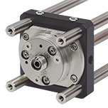 Click to Enlarge Click to Enlarge | CP08FP(/M)は、30 mmケージシステム内の中央にFiberPortが取り付けられるように設計されています。CP08FP(/M)は、30 mmケージアセンブリの4本のERロッドに固定できます。付属の4つの#2-56のステンレススチール製の六角穴付きネジで、FiberPortをアダプタに取り付けます。CP08FP/MにはSM1内ネジが付いているので、当社の豊富な種類のØ25 mm~Ø25.7 mm(Ø1インチ)レンズチューブと併用が可能です。さらにポスト取付け用にM4のタップ穴もあります。 |  Click to Enlarge | ポスト取付け用ブラケットHCPには、4つの#2-56の内ネジによりFiberPortを前面プレートに固定することができます。このL型ブラケットの底部には、M4ネジ穴とM6ネジ用のザグリ穴があるので、光学テーブル、ブレッドボードやポストに簡単に取り付けられます。 |
| FiberPortアダプタ、標準型HeNeレーザ用 | FiberPortアダプタ、5/8"-32ネジ付きHeNeレーザ用 | ||
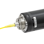 Click to Enlarge | このFiberPortアダプタHCLを使用すると、FiberPortをヘリウムネオン(HeNe)レーザに直接取り付けることができます。この取付けには業界のHeNeレーザで標準的なパターンの4つのボルト穴を利用しています。様々な取付け方法に対応するために、このHCLアダプタにはCマウントの内ネジもあり、これは一部のレーザで利用できます。取付け用ネジは付属しています。詳細についてはFiberPortの取扱説明書内のセクション5.1をご参照ください(PDFはこちらからダウンロードしていただけます)。 | 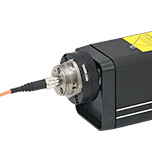 Click to Enlarge | 5/8"-32外ネジが切られたFiberPortアダプタHCL2をご使用いただくと、当社の電源内蔵型HeNeレーザのネジ付き開口や他の5/8"-32タップ穴のついた部品にFiberPortを直接取り付けられます。スリッププレート設計なのでFiberPortを結合効率が最大になるように移動して固定することができます。FiberPort取付け用ネジは付属しています。詳細についてはFiberPortの取扱説明書内のセクション5.1をご参照ください(PDFはこちらからダウンロードしていただけます)。 |
| FiberPortおよびFiberBench | |||
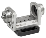 Click to Enlarge | 当社のファイバ-ファイバU-Benchは、FiberBenchに2つのFiberPortが組み合わさった構造です。U-Benchはファイバ-ファイバ用途に最適で、多数の部品を使いながら非常に高い安定性が求められる用途に適します。当社では光路中に取り付けることができる、豊富な種類の光学サブアセンブリを提供しています。当社では、2つのFiberPortをFiberBenchに取り付けたセットもご用意しています。 | ||
Insights:光ファイバ
こちらのページでは下記について説明しています。
- NAはファイバの受光角を表す指標となり得るか?
- MFDがシングルモードファイバにおいて重要な結合パラメータである理由とは?
- NAによりシングルモードファイバからのビーム広がり角がわかるか?
このほかにも実験・実習や機器に関するヒントをまとめて掲載しています。こちらからご覧ください。
NAはファイバの受光角を表す指標となり得るか?
Click to Enlarge
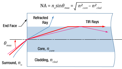
図1:入射角が≤θmaxの光線は、マルチモードファイバのコア内に閉じ込められます。これらの光線がコアとクラッドの界面で全反射するからです。
Click to Enlarge
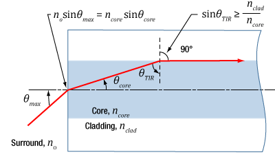
図2:コアとクラッドの境界での光の作用は、コアとクラッドの屈折率に依存し、端面に入射された光がコア内に結合するかを決定します。NAは幾何学的計算と、図の上にある2つの式を用いて求められます。
開口数(NA) は、ほとんどのマルチモードファイバにおいて図1のように最大の受光角を表します。この関係性はシングルモードファイバにおいては適用することができません。
開口数(NA)と受光角
入射光の光線モデルで、開口数と最大受光角(θmax )の関係性を表します。最大受光角は、軸外の光源からの光を集光できるファイバの能力を示します。図1の上にある計算式は、異なる光源からの光線がファイバのコアに結合できるかを判断するために使用できます。
入射角が≤θmax aの光線は、ファイバのコアとクラッド間の境界において全内部反射(TIR)します。これらの光線はファイバ内を伝搬していくので、コア内に閉じ込められたままとなります。
入射角がθmax よりも大きい光線については、コアとクラッド間の境界で屈折し、部分的に透過するので、結果的に減衰していきます。
関係性は幾何学によって定義されます
NA、θmax 、コアとクラッドの屈折率ncore とnclad の関係性は、図2で表すことができます。この図では、コアとクラッド間の境界で全反射が生じる最も極端な条件を示しています。
図2の上にある計算式は、スネルの法則によるもので、境界の両側における光線の挙動を示します。なお、式の簡易化でsin(90°) = 1が使用されています。θmax の値を制限するのはコアとクラッドの屈折率だけです。
入射角とファイバのモード
入射角が≤θmax のとき、入射光はマルチモードファイバの導波モードのどれか1つに結合されます。一般的に言えば、入射角が小さければ小さいほど、励起されるファイバのモード次数も小さくなります。次数が小さいモードは、強度をコアの中心近くに集中させます。次数が最も小さいモードは、端面に垂直に入射された光によって励起されます。
シングルモードファイバではご利用いただけません
シングルモードファイバの場合、図2のような光線モデルは使用できず、計算した開口数(受光角)は、最大の入射角度に等しくはなく、またファイバの集光能力を表すものではありません。
シングルモードファイバの導波モードは1つ、次数が最も小さいモードで、入射角が0°の光によって励起されます。しかし、NAを計算すると、その値は0ではありません。光線モデルでは、シングルモードファイバから放射、または結合された光線の広がり角を正確に予測することもできません。ビームの広がりは回折効果によって起こりますが、光線モデルにおいては考慮されていません。しかし、波動光学モデルによれば説明可能です。ガウシアンビームの伝搬モデルを使用すれば高確度でビームの広がり角を求めることができます。
最終更新日:2020年1月20日
MFDがシングルモードファイバにおいて重要な結合パラメータである理由とは?
Click to Enlarge
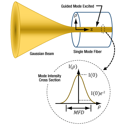
図3:最大の結合効率でシングルモードファイバに結合するためには、光が軸上のガウシアンビームで、ウェスト位置がファイバの端面にあり、ウェスト径がMFDと等しくなる必要があります。ファイバの出射光もこれらの特性によりガウス分布に近い形状となります。シングルモードファイバにおいて、開口数(NA)の使用した光線モデルは、結合状態を決定するには不適切です。ここでは半径( ρ )におけるモード強度(I )プロファイルが示されています。
光はシングルモードファイバを伝搬していくと、そのビーム断面の強度分布はガウス分布に似た形状となります。モードフィールド径(MFD)はこの強度プロファイルの幅を表します。入射ビームがこの強度プロファイルに合致すればするほど、より効率よく多くの光がファイバに結合します。入射されるガウシアンビームのビームウェストがMFDと等しいと、とりわけ高い結合効率が得られます。
ガウシアンビームの伝搬モデルにおいてMFDをビームウェストにすることで、確度の高い入射ビームパラメータと出射ビームの広がり角を得ることができます。
結合条件の決定
光ファイバの利点は、ファイバの導波モードによって伝播される光が放射線状には広がらず、最小限の減衰で伝搬していくことです。光をファイバの導波モードに結合するには、入射ビームと導波モードの特性を一致させる必要があります。導波モードに結合しない光はファイバの外に放射されます。光がファイバから漏れ出したと言えるのです。
シングルモードファイバの導波モードは1つであり、波動光学解析によってモードをベッセル関数で表すことができます。ガウス関数とベッセル関数の振幅プロファイルは、非常によく似ており(Kowalevicz氏。下記参考文献参照)、代わりにガウス関数を使用すると正確な結果をもたらしながら、ファイバのモードのモデリングが簡易化されるので便利です。
プロファイルは、径方向距離(I )プロファイルは、径方向距離( ρ )のガウス関数にほぼ一致します。MFDは、ファイバ長に沿って一定で、e-2とピーク強度の積に等しい強度の幅です。モードフィールド径(MFD)内は、ビームパワーの約86%が含まれます。
次数が最も小さい横モードだけが放射されるレーザ出力光はガウシアンビームとなるため、このレーザ光はシングルモードファイバに良い結合効率で結合できます。
シングルモードファイバへの光の結合
シングルモードファイバのコアに効率よく光を結合するには、入射するガウシアンビームのウェストをファイバの端面に合せてください。ビームウェストの強度プロファイルは、モードの断面の強度の特性と重複し、合致しなければなりません。入射ビームに必要なパラメータは、ガウシアンビームの伝搬モデルとファイバのMFDから求めることができます。
結合効率が小さくなるのは、ビームウェスト径とMFDが一致しない、端面のモーダルスポットによりビームの断面のプロファイルが歪んだり、中心がずれている、光がファイバの軸に沿って誘導されていない場合に起こります。
参考文献
Kowalevicz A and Bucholtz F, "Beam Divergence from an SMF-28 Optical Fiber (NRL/MR/5650--06-8996)." Naval Research Laboratory, 2006.
最終更新日:2020年2月28日
NAによりシングルモードファイバからのビーム広がり角がわかるか?
開口数(NA)を使用してシングルモードファイバから出射される、あるいはシングルモードファイバに結合する光円錐を概算する場合、大きな誤差が生じる場合があります。広がり角はガウシアンビーム伝搬モデルを使用した方がより良い概算値が得られます。このモデルにより、広がり角を算出し、用途に適したビームスポットサイズを得ることができます。
シングルモードファイバにおけるモードフィールド径(MFD)内は、ビームパワーの約86%が含まれるため、MFDによりスポットサイズを決めることは、シングルモードファイバから光をコリメートしたり、光を集光する際の適切な定義であるとされています。一次近似でファーフィールドで測定されたとき、
 , , | (1) |
は、広がり角または受光角(θSM )(単位:ラジアン)です。これは1/2ビーム角で、波長 )
)
| Rayleigh Range: | ||
 | ||
| Beam Radius at Distance z: | ||
 | ||
図4:青い線は、シングルモードファイバからの出射光の広がり角(θSM )をNAを用いて計算した結果を示しています。赤い線は、ガウシアンビーム伝搬モデルを使用して計算されており、これにより、ビームスポット径の大きな誤差を回避することができます。 こちらのグラフではSM980-5.8-125からのビームをモデル化しています。NAは0.13、MFDは6.4 µmの値を使用しています。動作波長は980 nm、レイリー範囲は32.8 µmでした。 | ||
ガウシアンビームによるアプローチ
シングルモードファイバの端面から出射される光は円錐状に広がりますが、この光はファイバ軸から様々な角度で出力する複数の光線と同様の振る舞いにはなりません。
この光はガウシアンビームに似ており、モデル化ができます。放射光がガウシアンビームと同様に伝搬するのは、光の導波モードがガウス分布に近似しているからです。
ガウシアンビームの広がり角は、光線として作用する光を想定して計算された広がり角度とは実質的に異なります。光線モデルを使用した場合、広がり角は sin-1(NA)となります。しかし、NAと広がり角の関係性は高次マルチモードファイバのみ有効です。
図4では、NAを使用して広がり角を計算すると大きな違いが生じる可能性を示しています。 ガウシアンビームでは、広がり角はビームパワーの86%を含む領域とされており、この領域の境界円における強度は、ピーク強度の1/e2となっています。
図4の右の式は、シングルモードファイバ端面から出射されるビームの広がり角を正確にモデル化するガウシアンビームの式です。計算に使用するファイバのMFD、NAならびに動作波長を含む値はグラフ下に記載されています。ビーム発散角は、 1/e2半径によって定義されたビームサイズの変化により算出されています。ビームサイズは、z < zRの距離においては非線形で、ファーフィールド(z >> zR)においてはほぼ線形に変化します。
グラフに記載されている角度は各曲線の傾斜から計算されました。式(1)で求めたファーフィールドの概算が使用された場合、広がり角は0.098ラジアン(5.61°)です。
参考文献
Kowalevicz A and Bucholtz F, "Beam Divergence from an SMF-28 Optical Fiber (NRL/MR/5650--06-8996)." Naval Research Laboratory, 2006.
最終更新日:2020年2月28日
Content improved by our readers!
| Posted Comments: | |
Viktor Dubec
(posted 2024-04-08 15:14:50.677) Hello, what is the tolerance of the opening where the fiber is inserted? I have got following task: I want to use 50um core multi-mode fiber because my laser spot in the focus is around 40-50um. In can do the alignment easily and I get over 80% efficiency. But after I remove the fiber and insert it back, the alignment is lost. Is there any solution how to make this process repeatable without new alignment? Or is it impossible due to small mechanical dimensions and tolerances of the coupler and fiber? Thank you! Francois Parnet
(posted 2024-01-30 10:14:40.54) Hello, I can't find the distance between the FC/APC end tip of the pigtail inserted into the Fiberport and the lens. Only the length L between the FC/APC connector and the metal package is given. I need to know what is the excursion of +/-1mm for this PAF2A-18C component.
Thank you cdolbashian
(posted 2024-02-02 09:50:30.0) Thank you for reaching out to us with this inquiry. Looking at the lens used within this component, it seems that while the focal length is ~18.4mm, the working distance is closer to 17mm. With this fact, we design the fiberport such that the WD of the lens is coincident with the tip of the fiber when the Z translation is at its zero position. In this sense, this will allow +/-1mm travel to optimize collimation/coupling. I have contacted you directly to discuss this. Craig Prater
(posted 2023-11-22 13:56:34.933) So far, I am extremely disappointed with this product. I find the FiberPort devices to be extremely difficult to use and not stable over time. The most frustrating aspect is that I am seeing uncontrolled shifts in the relative position of the coupling optics to the fiber that has on at least five occasions has led to complete or almost complete loss of coupling of light into the fiber. On several occasions, I have been very close to maximizing the light coupling when there was a sudden loss of coupling even when I was nowhere close to the unit. After the loss of coupling, I find the new optimal coupling position and focus way off of the previous location, for example up to half a turn of the Z-theta adjustment screws. I have seen this behavior with two different FiperPort couplers I bought. (I am also confident that the problem is associated with the FiberPort couplers and not some other component in my optical system because I am coupling the same laser beam via a beam splitter into the two different FiberPorts and I will see one or the other coupler suddenly lose coupling, while the other is still coupling ok. So it is not any upstream optics. I also find the units very difficult to use because the heads of the adjustment screws are so small, it is very difficult to get an Allen wrench into the the adjusters, especially the z-theta two adjuster which is below the other two adjuster where it is difficult to see and difficult to access. I also find that the XY adjustments are not very smooth with lots of backlash and some cross-coupling. I bought these units to test for possible inclusion in an OEM product, but with my current experience, I can't imagine including these couplers in a product.
At this stage I would like some guidance about other options that will be more robust for single mode fiber coupling. jpolaris
(posted 2023-12-04 05:10:55.0) Thank you for contacting Thorlabs. Your feedback is valued, and I am sorry that you have been having a difficult time with our FiberPorts. I have reached out to you directly to discuss your setup and to explore possible reasons for the issues you are experiencing. Our FiberPorts are designed with stability (mechanical and thermal), repeatability, and functionality in mind. For this reason, I find your description of the issue surprising -- especially the part about you losing coupling while nowhere near the FiberPort. Single-mode coupling is notoriously tricky, so I have reached out to you to try to identify if the issues you are experiencing are procedural (alignment technique) or mechanical (faulty FiberPort) in nature. We provide a FiberPort alignment procedure located at the following link. Following this procedure helps ensure that you do not find yourself at local unstable coupling efficiency maxima. As you home in on the "true maximum" coupling efficiency, you will pass through these local maxima. When this happens, it is completely normal for the coupling efficiency to temporarily rise to a peak, then fall off dramatically. This process will continue until you've found the ideal adjustor positions. The alignment procedure can be found here: https://www.thorlabs.com/newgrouppage9.cfm?objectgroup_id=2940&tabname=Alignment_Procedure Yuheng Huyan
(posted 2023-11-13 17:14:02.3) Dear Thorlabs,
Does the coupler performs the same for high power laser? Is the coupling efficiency power dependent?
Best,
YH cdolbashian
(posted 2023-11-29 02:01:17.0) Thank you for reaching out to us with this inquiry. The effect you could potentially see would be thermal lensing, when using a high power laser and considering the coupling efficiency. Alternatively, you could potentially damage the lens inside or strip the anti reflective coating. I have contacted you directly to inquire regarding your optical setup, laser parameters, and eventual experimental requirements. user
(posted 2023-07-07 14:49:47.403) Hello, We recently purchased a PAF2S-2B. I would like to access to a Zemax file of the aspheric lens, such as to modelize further the beam.
Is it possible to get one by email ?
Thanks. cdolbashian
(posted 2023-07-13 01:58:35.0) Thank you for reaching out to us with this inquiry. Thankfully the lens inside this FiberPort is a stock asphere: 355151-B. The Zemax files can be found here: https://www.thorlabs.com/thorproduct.cfm?partnumber=355151-B ChangYi Lin
(posted 2023-06-05 19:31:03.607) Dear Thorlabs, I would like to ask some questions about my multimode fiber laser. I need to use a 915nm CW fiber laser. Its NA is 0.22, core size is 200um, and connector is SMA905. Is it suitable with PAF2S-2B? What is the coupling efficiency? How to estimate the beam divergence angle after passing through PAF2S-2B? core size/focus = 200um/2mm=0.1rad? Thank you. cdolbashian
(posted 2023-06-12 01:39:25.0) Thank you for reaching out to us with this inquiry. In order to understand your application and intent, I have contacted you directly. For future technical/usage inquiries, please contact techsupport@thorlabs.com. Tobias Kuhnke
(posted 2023-03-13 13:39:49.083) Dear Thorlabs,
I am using multiple PAF2A-15C Ports for coupling 1310 nm SLED radiation in between single mode fibres with different base plates yielding 5 cm and 10 cm distance between the ports.
During the alignment process we've found out that the coupling efficiency is highly dependent on an optimal z-value between the ports for higher working distances. Sub-optimal z-values will drag down coupling efficiency when working with higher working distance.
One finds optimal z-values by subsequently increasing the working distance and adjusting z-theta for z-value. When z is optimal, a small change in x- and y-axis value will drop coupling effiency sharply. jgreschler
(posted 2023-03-13 02:40:02.0) Thank you for your valuable feedback regarding fiber coupling with our FiberPorts. I have reached out to you directly to suggest some tips and tricks to make the process of fiber coupling a little easier! We also have a video demonstration of one of our engineers bringing their efficiency to 80% here which is great to follow along with https://youtu.be/0HejWlZj0LU. zhang Aaron
(posted 2022-09-25 01:26:14.297) FiberPort 产品型号为PAF2-5B 中近光纤连接器端的透镜破损,请问有替换元件吗 cdolbashian
(posted 2022-10-04 04:15:27.0) Thank you for reaching out to us. If you have a broken component in one of your products, please reach out to Techsupport@thorlabs.com to troubleshoot and identify the issue. I have reached out to you in this situation to troubleshoot your device. YU DONG
(posted 2022-08-31 09:05:01.813) What is the coupling efficiency of the coupler and the laser emission wavelength is 532nm. Ilan Sher
(posted 2022-08-14 23:20:51.903) Hello, I trying to couple laser to the PAF2A-11B collimator sitting on the HCP L-Bracket Mount to PM fiber. I noticed that the colimator is tilted even with all Ztheta screws is losen so the tiltplate supposed to be straight. How can i fix that tilt to make the coupling efficient? Thanks jgreschler
(posted 2022-08-25 10:26:15.0) Thank you for reaching out to Thorlabs. I have reached out to you directly to discuss troubleshooting, and set up a return for repair on your unit of PAF2A-11B. M Eskandari
(posted 2021-12-28 03:01:59.553) Hello,
I have bought a free space single-photon detector from MPD (http://www.micro-photon-devices.com/Products), but now I'm going to modify it to a fiber-coupled version.
I think by attaching PAF2P-15B and a simple mechanical adapter on the detector, I can direct the 810 nm light on the 50 um effective area of the detector.
Is this part suitable?
Regards jgreschler
(posted 2022-01-04 11:22:46.0) Thank you for reaching out to Thorlabs. I have reached out to you directly to discuss your application further. Yong Guk Kang
(posted 2021-12-07 23:47:26.143) Hello, I am trying to catch and launch the free space SLD beam to the single-mode fiber. (780)
the bandwidth of free space SLD beam is around 800~850nm, and its collimated beam diameter is 2.5mm.
for best efficiency, which one should I use? PAF2A-A10B (output dia. 2.16 mm)or PAF2A-A15B(output dia3.25mm) ?
regards, jgreschler
(posted 2021-12-14 09:07:35.0) Thank you for reaching out to Thorlabs. The parameter that will dictate whether your input beam clips the lens is actually the clear aperture (CA) of the system. In both items the CA spec is 4.5mm, which is more than enough for a 2.5mm input beam. Given your fiber's NA and MFD specs the PAF2A-A10B is the correct choice for this application, which is in agreement with the FiberPort calculator in the Selection Guide tab of this product page. Paul D
(posted 2021-11-26 09:08:25.307) Hi,
We are currently using the PAF2-2A and it's a great product. Do you plan to release an achromatic FiberPort with a 2-mm focal length? The shortest focal length of your achromatic FiberPort (4mm) is too large for our optical system.
Thanks YLohia
(posted 2021-12-10 02:14:45.0) Hello, thank you for your feedback. Unfortunately, we don't have any plans of releasing shorter focal length achromatic Fiberports in the near-future. That being said, we have noted your request and hope to look into a solution for this. Bethany Foxon
(posted 2021-09-08 04:34:44.083) Hello, do you have the ZMX file for the the PAF2-5A? Thank you YLohia
(posted 2021-09-08 12:01:15.0) Hello, we don't offer Zemax files for the entire FiberPort assembly but we are able to offer Zemax files for the component lenses used in the FiberPorts in most cases. The PAF2-5A uses the A390-A lens and its Zemax file can be found here: https://www.thorlabs.com/thorproduct.cfm?partnumber=A390-A. jia gao
(posted 2021-06-21 10:35:12.59) We used the fiber coupler to align four lasers with different wavelength. But adjusting the knobs on the mirrors and x y a on coupler. We successfully adjusted the efficiency for all four lasers to 50%. However, when we came to lab another day, the efficiency dropped dramatically to micro again… we wonder if it is due to the fiber coupler too sensitive? Should we lock the x y after setting. YLohia
(posted 2021-06-28 10:18:24.0) Thank you for contacting Thorlabs. Please check the long term / temperature related drifts of your collimated beam going into the PAF. In the event of a positional drift of the beam, the coupling efficiency can drop significantly. It is recommended to lock the X-Y adjusters once alignment has been completed. Kais Almarzouk
(posted 2021-05-20 18:09:45.25) Do you have a Zemax copy of this item (PAF-X-18-B)? If you do can you email it to me. Thank you. YLohia
(posted 2021-05-21 10:54:50.0) Hello, I have reached out to you directly regarding this. Jaemin Song
(posted 2021-05-19 00:36:21.53) Hi,
I am looking for a collimator for the range of wavelengths between 400nm and 900nm.
So, I found PAF2S-A7A as one of my collimator systems.
However, I am a little confused with the possible transmission and collimating range.
The wavelength range of the AR coating is 400-700 nm, while the transmission range of materials(N-BAF10 / N-SF6HT) is starting from about 600 nm.
Then, this collimator only be used within 600 ~ 700 bm wavelength. Am I right?
please, check the AR coating and lens material of PAF2S-A7A.
Thank you. YLohia
(posted 2021-05-19 01:34:25.0) Hello, thank you for contacting Thorlabs. The PAF2S-A7A can still be used for its specified wavelength range of 400 - 700 nm, but the internal transmission in the 400-600 nm range will be roughly 80-95%. If the loss due to transmission isn't too high for your application, the PAF2S-A7A can still be used. Alex C
(posted 2021-05-11 11:32:45.257) I’m currently working on a project using 2 Thor labs FIberPorts that seem to be discontinued, and one of them I can not find the serial number on your website is it possible to get the specifications for these? One the serial PAF-X-7-780 and the other is PAF-X-7-B. The -780 has a longer connection port. Any information/specifications would be greatly appreciated. YLohia
(posted 2021-05-12 11:03:30.0) Thank you for contacting Thorlabs. The specs for PAF-X-7-B can be found here (https://www.thorlabs.com/catalogpages/obsolete/2018/PAF-X-7-B.pdf) or here (https://www.thorlabs.com/_sd.cfm?fileName=16164-D02.pdf&partNumber=PAF-X-7-B). We don't have any item number PAF-X-7-780 in our system. Vijay C
(posted 2021-03-22 22:31:27.1) Hi,
What is the difference between the item PAF2P-18C and PAF2A-18C. Since both looks same, I am confused to choose the right product for my application. YLohia
(posted 2021-03-23 10:24:58.0) Hello, the PAF2P-18C has FC/PC connectors while the PAF2A-18C has FC/APC connectors. Jens Flügge
(posted 2021-03-09 05:28:03.527) Ladies and Gentlemen,
are the FiberPort Collimators also avalable for
vacuum (10^-4 mBar range) ?
Kind Regards YLohia
(posted 2021-03-09 11:38:19.0) Thank you for contacting Thorlabs. Unfortunately, we cannot guarantee vacuum performance of these due to lack of test data. While we don't foresee a catastrophic event, outgassing is expected to cause problems. The grease used is Krytox LVP, which is vacuum compatible. Most components are 303 stainless steel. The only plastic is PTFE. The lenses are attached with F113 and Armstrong A-12, which may outgas significantly, but only small amounts are used. If you would like to attempt using the FiberPort in vacuum, we would suggest removing the aluminum tilt plate cover and the adhesive that attaches it. This would be entirely at your risk, as we cannot guarantee the performance for this application. Greg Whitfield
(posted 2021-03-03 11:23:29.077) I am interested in using the PAF2 fiber alignment positioner without a lens. Is this possible? asundararaj
(posted 2021-03-03 03:48:31.0) Hello, thank you for contacting Thorlabs. Quotes for custom items can be requested by clicking the red "Request Quote" button above or emailing your local Thorlabs Tech Support team. We have reached out to you directly to discuss the possibility of offering this custom. user
(posted 2020-08-12 18:38:51.23) I wanted to have a solution to couple the collimated light coming from a broadband source (like the SLS201L with the SLS201C collimator) into a SM fiber with an MFD of ~10um and NA=0.23. I understand that it would be challenging to couple all the wavelengths into a SM fiber. The best possible solution that I could see was with the achromatic fiberports (even if I will not be able to sample the entore beam size of the SLS201L source). What would you suggest? nbayconich
(posted 2020-08-13 03:40:33.0) Thank you for contacting Thorlabs. It is not recommended to attempt to couple light from a broadband light source such as the SLS201L into any type of single mode fiber. With or without a fiberport system, the coupling efficiency will be extremely low and not suitable for most applications.
I will reach out to you directly to discuss your application. chi xu
(posted 2020-03-05 15:01:50.03) What is the max laser power this fiber-port/coating can handle?@1550 nm nbayconich
(posted 2020-03-05 03:40:35.0) Thank you for contacting Thorlabs. We have not yet tested the pulsed or CW damage threshold for these particular fiberport lenses however, in most cases the maximum power that can be used will be limited to the fiber connector's epoxy. I will reach out to you directly to discuss your application. abhishek akn
(posted 2019-11-26 08:56:28.963) Hello, Please let me know the damage threshold for PAF2A-18B fibreport collimator. I will be using it with 100mW FC/APC laser module with pulse repeatation 10MHz, 10ns pulse width. nbayconich
(posted 2019-11-27 10:00:02.0) Thank you for contacting Thorlabs. We have not yet tested the pulsed damage threshold for these particular lenses however given the low average power and low pulse energy density of your source, we would not expect your source to damage these lenses used in this fiberport collimator. user
(posted 2019-08-09 07:46:04.487) Hello. I need to lock the X Y position of the lens in the PAF2A-18B fibreport collimator. I understand the iteratice process of tightening the locking screw then the X and Y screws. The manual says it is locked when the X, Y and locking screws are "snug". Does this mean until you can no longer tighten the screws please? Would I need to tighten the X-Y tension screws as much as possible beforehand? YLohia
(posted 2019-08-19 10:57:19.0) Hello, The X,Y, and LOCK screws should be tightened as much as possible while still maintaining alignment. Over-tightening can damage the device as these are small screws in a precision device. You should be able to tighten to ~1.5 in-lbs before causing damage. The order of operation is with XY screws in position to achieve desired alignment before engaging lock screw. Use X, Y, and Lock screws to maintain alignment while generally tightening to achieve lock. Paul Mason
(posted 2019-08-01 05:57:07.66) Please confirm the PAF2-5B is supplied with a dust cover. If not please can you let me know the part number for a dust cover compatible with the PAF2-5B and the price of the dust cover.
Many thanks
Paul YLohia
(posted 2019-08-01 11:32:19.0) Hello Paul, these FiberPorts include a dust cap. Additional caps can be purchased from the website using part number CAPX1. Ivan Skachko
(posted 2019-07-23 06:14:45.993) Hi
I used FiberPort Coupling Calculator with the following parameters: aspheric lens, MM fiber, 640nm, SMA, beam diam=2mm, NA=0.1. The calculator returns: "There may not be a FiberPort that meets your input parameters..." However I do not see why, for example, PAF2S-11B would not be a suitable choice for my situation. Is there something I am missing?
I am trying to couple 2mm HeNe laser beam into SMA terminated FG105LVA-Custom Patch Cord from Thorlabs.
Very Best Regards
Ivan tcampbell
(posted 2019-07-23 10:38:19.0) Hello, thank you for contacting Thorlabs. Currently, the calculator looks for a FiberPort with an NA less than or equal to the value entered by the user. We will look into refining the parameters in the tool so that cases like yours do not return a null result. In the meantime, a member of our Tech Support team will reach out to you to help you decide on a suitable FiberPort. Yu D
(posted 2019-07-05 15:36:22.7) Whether the spatial light passes through the collimator can be coupled to a single mode or a fiber of about 100 um with less loss. If not, can you recommend the relevant device to us? YLohia
(posted 2019-07-08 03:51:44.0) Hello, thank you for contacting Thorlabs. The FiberPort couplers on this page are designed for high-efficiency coupling into single mode fibers. Multimode fibers can be used as well with even better coupling efficiencies. user
(posted 2019-07-02 10:01:45.837) Hello, can the PAF2-5B be used with a 1064nm Laser while achieving reasonable efficiency? YLohia
(posted 2019-07-02 04:31:54.0) Hello, thank you for contacting Thorlabs. This depends on how you define "reasonable efficiency". If you're specifically worried about operating this slightly outside of the AR-coating range, you shouldn't see a major drop in performance. Please see our typical reflectivity curve for the -B coating here : https://www.thorlabs.com/images/TabImages/B_Broadband_AR-Coating.xlsx. The PAF2-5B is the same as the PAF2-5C, except for the coating on the lens used. Lukasz Ambrozinski
(posted 2019-05-07 17:09:12.59) Hello,
Can PAF2 fiberPort couplers be used to couple 1053 nm laser beam of the diameter of 0.7 mm to this fiber https://www.thorlabs.com/thorproduct.cfm?partnumber=MHP910L02 ?
Thank you,
Lukasz YLohia
(posted 2019-05-08 08:44:15.0) Hello Lukasz, thank you for contacting Thorlabs. Yes, the PAF2 FiberPorts can be used for this application (we would specifically recommend looking into the longer focal length units such as the PAF2S-18C in this case). Tommy Nguyen
(posted 2019-03-27 19:22:59.65) Dear Thorlabs,
We are trying to dual-couple 488nm and 640nm lasers into a single mode FC-PC Polarization maintaining fiber (P1-488PM-FC-2). For this we were considering on using the PAF2-2A fiberport; however, we were wondering if it is possible to exchange the lens for different applicaitons. Is this possible?
As another question, we are using the above fiber to collimate 488nm and 640nm light out of the fiber with a approximate desired beam waist of 3mm. This would require an effective focal length around 15mm. Do you have anything you reccomend? YLohia
(posted 2019-03-28 09:39:00.0) Hello, thank you for contacting Thorlabs. We strongly recommend the achromatic FiberPorts (such as the PAF2-A4A) for applications that require dual wavelength coupling into single mode fibers. Even a slight focal length shift between the wavelengths in cases such as this can result in noticeable coupling losses. That being said, we are able to swap out lenses, though this is something we would have to bring the item back in for (the lens replacement is not serviceable by the user). We are currently in the process of looking into expanding the achromatic FiberPort line and we hope to have longer focal lengths available in the future. Currently, however, you may be able to use the RC04FC-P01 reflective collimator with EFL = 15mm for your dual wavelength beam. We recommend using this with the K5X1 5-axis kinematic mount for proper alignment. user
(posted 2019-03-21 18:08:11.367) I am looking for a coupler to inject 325nm laser (bram diameter 1.2mm) into single mode fiber. However, the only fiber that I found from Thorlab (SM300) has NA much smaller than the one fof the couplers here. Can I still able to couple light into these fibers ? Thanks YLohia
(posted 2019-03-25 10:02:15.0) Hello, thank you for contacting Thorlabs. You can still couple light into the SM300 fiber with one of these collimators. There will, however, be a noticeable loss in power due to this NA mismatch (fiber NA ~0.12 with coupler NA 0.15). If spatial mode profile isn't important to your application, we recommend looking into our multimode fibers that will offer you a higher NA and coupling efficiency. ganzfei
(posted 2019-03-08 15:18:38.137) I have bought your product PAF2-5A and I want to couple a laser beam into a fiber. The illustration said the efficiency can be 60 to 80% but I have tried many times the efficiency does not exceed 30%. Could you help me with this issue? llamb
(posted 2019-03-13 08:07:06.0) Thank you for your feedback. Please refer to the Selection Guide tab on this webpage to ensure you have chosen the correct FiberPort for your application. It is crucial to consider wavelength, fiber type, fiber core size, and input beam diameter. Then, be sure to refer to the Alignment Procedure tab on this webpage for additional tips. After pre-aligning your FiberPort so its tilt plate is orthogonal to the optical axis, we recommend using two mirrors and an iris to help steer your input beam to be on-axis into your FiberPort. I have reached out to you directly with additional tips and troubleshooting steps. 17888819024
(posted 2019-03-07 16:28:34.71) In the selection guide,the method is about single wavelength.I want to transmit light of multiple wavelengths,but I do not know how to select the FiberPort.Please teach me. YLohia
(posted 2019-04-05 03:05:45.0) Hello, we have been in direct contact with you since the original posting. Most of the FiberPorts on this page (as of 4/2019) are designed for single wavelength applications. That being said, we do offer achromatic FiberPorts (PAF2-Axx series) that are designed for broad wavelength ranges. The achromatic design of the lenses used minimizes the chromatic focal length shift. lebouquj
(posted 2019-03-05 19:36:13.853) Hi, is it possible to buy only the bulkhead and the adjusters, but without the lens. That would be a very useful tool for custom free space launching. Thanks. YLohia
(posted 2019-04-05 02:57:56.0) Hello, thank you for contacting Thorlabs. Custom/special items can be requested by emailing techsupport@thorlabs.com or clicking the red "Request Quote" button above. We have reached out to you directly to discuss your application and requirements. 2014170094
(posted 2019-01-14 01:43:23.05) We had bought some FiberPorts(PAF-X-2-C),but now we can't find this item in website.Would you please offer some information about it? Thank you for your attention. mmcclure
(posted 2019-01-14 09:51:53.0) Thank you for contacting us. We recently redesigned and improved all our FiberPort products. The PAF-X-2-C has been superseded by the PAF2-2C. However, information about the PAF-X-2-C can be found here: https://www.thorlabs.com/thorproduct.cfm?partnumber=PAF-X-2-C. Should you have additional questions concerning your FiberPort, please reach out to our Thorlabs technical support team. We are happy to assist you! laurent.brilland
(posted 2018-12-21 12:02:01.167) Hello
I have unfortunatly damaged the lens of the fiber port PAF2-4E.
How can I proceed to replace the lens ? If I order a new lens, do you have a procedure to change it ?
Best regards
Laurent YLohia
(posted 2018-12-21 09:53:21.0) Hello Laurent, customers cannot change the lens in our FiberPorts. Please contact your local Thorlabs Tech Support team (techsupport.fr@thorlabs.com) to set up a return for repair. mskang
(posted 2018-12-02 20:12:46.783) I am going to use TC12FC-780 of triplet collimator for repeatability of collimator.
How is the repeatablily function of this PAF2P-11B comparing with triplet collimator?
Is this PAF2P-11B having big difference for repeatability? because repeatability funcion is very important point. nbayconich
(posted 2019-04-09 04:20:05.0) Thank you for contacting Thorlabs. In terms of repeatability are you looking for insertion repeatability for the fiberport and triplet collimators or pointing error repeatability such as the graphs provided on our triplet collimator page below?
https://www.thorlabs.us/newgrouppage9.cfm?objectgroup_id=5124
At the moment we only have insertion repeatability test data for the fiberports but no pointing error repeatability to compare to the triplet collimators.
In terms of repeatability for the PAF2 series fiberport collimators there are 3 possible sources of error.
1) Connector ferrule fit to bulkhead.
2) Movement of lens relative to fiber.
3) Movement of device relative to target.
Please let us know specifically what type of repeatability you are looking for. I will reach out to you with some insertion lost repeatability testing our engineers have performed on our fiberport collimators. laurent.brilland
(posted 2018-11-15 10:43:36.09) Hello
I'll need to use the device PAF2-4E but with the 8-12 µm Ar coating. Is it possible to change the lens ? (the 390036F seems ok ?)
Best regards
Laurent YLohia
(posted 2018-11-15 10:14:10.0) Hello Laurent, thank you for your inquiry. I will reach out to you directly to discuss the possibility of offering this. mfernholz
(posted 2018-07-30 15:50:49.69) Dear Madam or Sir,
I recently acquired the predecessor of the PAF2-A4A, the PAFA-X-4-A. I happened to have lost the locking screw, which should be a 0-80, 0.050" screw. Unfortunately, neither the length, nor whether the end is coated in rubber was stated in the manual and hence replacement has been difficult (also, since this is an imperial screw and I work in Europe). Is there a way to supply me with a replacement for the locking screw of the PAFA-X-4-A (I assume the screws remained the same for the PAF2-A4A)? If you need further information, please feel free to contact me.
Best regards,
Martin Fernholz YLohia
(posted 2018-08-02 11:36:22.0) Hello Martin, thank you for contacting Thorlabs. These are actually #0-80 x 1/4" socket head cap screws and are not rubber-coated. For quotes on any custom items or component parts, please contact your local Thorlabs Tech Support (europe@thorlabs.com). We will reach out to you directly with a quote for the replacement screws. caozengle
(posted 2018-05-23 10:37:54.243) Hi, I want to know if bulkheads of different models are exchangable. I have a PAF2P-11A (11 mm, PC) and a broken PAF-X-15-A (old model, 15 mm, APC), I simply changed PAF2P's PC bulkhead with the APC one and happily to found it works well. I want to know if APC (or PC) bulkheads of 11 mm and 15 mm models are exactly the same, also are APC and PC bulkheads exchangable with the same focal length. nbayconich
(posted 2018-05-24 09:15:16.0) Thank you for contacting Thorlabs. Yes the bulkheads for the 11mm & 15mm FC/PC fiberports are the same type so these can be interchanged. The bulkheads of the 11mm & 15mm FC/APC fiberports can also be switched with one another. The bulkhead used in a fiberport will be determined by the focal length, all bulkheads in fiberports with focal lengths of 2-7mm are interchangeable. Fiberports with focal lengths of 11-18mm will use a different set. saurabh.raj
(posted 2018-04-12 14:46:09.737) What would be the best coupler for a fiber with FC/AFC end? I have searched your webpage, but can't find couplers for AFC fibers. YLohia
(posted 2018-04-12 11:18:46.0) Hello, thank you for contacting Thorlabs. There is no such thing as an FC/AFC connector for fibers. Perhaps you mean FC/APC? If that is the case, we have many APC compatible couplers on this page. I have reached out to you directly to discuss your application further. user
(posted 2018-04-07 17:17:20.013) I don't like that the new fiber port has both metric and SAE screws. It sucks to strip out a screw because I forgot they are different, and used the closest sized wrong allen wrench. It would be nice if there was consistent hardware, either all metric or all SAE. nbayconich
(posted 2018-04-10 05:34:03.0) Thank you for your feedback. Our apologies for the inconvenience this may have caused, please note that all adjusters for these fiberports use imperial hex keys. TCampbell
(posted 2018-04-04 11:31:30.037) A note from Tim at Thorlabs:
As an update to the previous comment, please note that a new generation of FiberPort Collimators were released on March 20, 2018. For more information on the new design, please see the tabs above. We look forward to hearing feedback on the improved features! david.lavan
(posted 2018-02-21 14:54:56.21) This may be the worst product Thorlabs sells. Between arriving missing a spring, and being almost impossible to adjust to generate a signal with a SM fiber, it is a a sure fire way to turn thousands of dollars of lab time into vapor. nbayconich
(posted 2018-03-01 02:48:36.0) Thank you for your honest feedback. The design of these FiberPort collimators is outdated, and in an effort to make them more compact, significant crosstalk arose. We will be shortly releasing a new version of our FiberPort collimators, the new design will mitigate positioning errors from hysteresis, and over travel of the Z axis. Some improved features of our new FiberPort collimators will include M2X0.2 fine adjusters and will no longer have plunger screws to provide a counterforce against the adjuster screws but will contain retention springs to provide counterforce. I will reach out to you directly to discuss performance changes. tanmaybhwmk3
(posted 2017-10-25 23:14:45.83) What is the damage threshold for the product "PAF-X-7-A"? Can I use it for 800 mW CW 532 nm laser with Multimode fibre? tfrisch
(posted 2017-10-30 12:11:44.0) Hello, thank you for contacting Thorlabs. The maximum power that can be used in a FiberPort will depend on many factors. Whether it is used for collimating out of fiber or coupling into fiber, overfilling the lens or fiber will expose epoxy to high power, and that will likely be the limiting factor. I will reach out to you to discuss your application, but in general, it is best to align the system at low power and increase power only once the transmission is maximized. user
(posted 2017-09-01 16:58:35.093) Hello,
I have a question concerning the waist at the collimator output and the MFD :
I want to use a PAF-X-11-C and a P3-1064PM-FC.
Using the given formula at 1064nm I get :
d = 4*(1064nm)*11mm/(pi*7.7µm) = 1.9 mm
Is this correct ? Can I take whatever fiber (i.e. MFD) I want ? tfrisch
(posted 2017-09-15 10:12:20.0) Hello, thank you for contacting Thorlabs. The calculation of beam diameter you give above looks correct for a diffraction model of the propagating light. The geometric model would give the diameter as roughly 2*f*NA of the fiber, and though these are not equivalent, they are both widely used definitions. The MFD of a fiber will be dependent both on the wavelength of the light and the core geometry, so changing the fiber will slightly change the above parameters. Please contact TechSupport@Thorlabs.com to discuss this in detail. user
(posted 2017-09-01 15:33:48.323) Hello,
I will need 3 collimators :
PAF-X-11-C
PAF-X-5-C
PAF-X-5-A
but I need them vacuum compatible down to 10^-7 mbar, is this possible ? If not do you propose vacuum compatible collimators ? tfrisch
(posted 2017-09-15 09:47:09.0) Hello, thank you for contacting Thorlabs. We would love to discuss the needs of your application through TechSupport@Thorlabs.com. We look forward to hearing from you. inzenith
(posted 2017-06-21 17:56:35.43) Hello, I need collimator or lens for collimating and focusing purpose (broadband wavelengths 400-1000) in Fiber Optics, What do you recommend? tfrisch
(posted 2017-06-27 01:27:38.0) Hello, thank you for contacting Thorlabs. You may want to consider a reflective collimator for broadband performance. I will reach out to you directly about your application.
https://www.thorlabs.us/newgrouppage9.cfm?objectgroup_id=4093 inzenith
(posted 2017-06-21 17:53:32.417) Hello, I need collimator or lens for collimating and focusing purpose in Fiber Optics, What do you recommend? tfrisch
(posted 2017-06-27 01:23:12.0) Hello, thank you for contacting Thorlabs. It looks like you have posted a duplicate request where you elaborate that your source is broadband. You may want to consider a reflective collimator. I will reach out to you about your application. bw
(posted 2017-03-30 13:59:08.19) What is the purpose of the captan tape on the fiber port's face? My intuition is to remove this prior to installation and use; however, there is no mention of it in your documentation and there is no illustration of the face side. It is good that you documented the alignment options; but if removing this tape ruins the port, that fact should also be documented. tfrisch
(posted 2017-03-31 04:38:30.0) Hello, thank you for contacting Thorlabs. This tape can be removed. I have passed your feedback on to our Fiber Team. diemel
(posted 2017-02-17 05:10:45.607) Is there data available for the focal shift of the PAF-X-4-E? tfrisch
(posted 2017-02-17 09:27:18.0) Hello, thank you for contacting Thorlabs. I will reach out to you directly with details on the component lens (390036). schaefer
(posted 2016-11-30 11:22:45.46) Hi!
I have a question about the fiber ports PAFA-X-4-A and PAFA-X-4-B: Can I just change the bulkhead to SMA to use it with SMA fibers? And if so can I buy those separately?
thanks! tfrisch
(posted 2016-11-30 01:55:28.0) Hello, I have contacted you directly about the quantity of bulkheads you need. We will have a quote sent to you. user
(posted 2016-10-17 17:28:15.953) To couple out put of each HeNe into single mode fiber, can you put a list of suitable part numbers at somewhere in a tab also coupling ratio, too? jlow
(posted 2016-10-18 04:17:49.0) Response from Jeremy at Thorlabs: This would depend on the beam size from your HeNe and also on the fiber that you are using. For a typical HeNe with around 0.8mm beam diameter and a typical SM fiber with about 4µm MFD, the PAFA-X-4-A would work. You can see the Selection Guide tab on how to choose the proper FiberPort. In terms of mounting the FiberPort and HeNe, it also depends on how you want to mount them (e.g. post vs. cage system). If you need help with this, you can contact us at techsupport@thorlabs.com. CChang
(posted 2016-07-05 14:25:42.837) Dear Thorlab
I have a question about the fiber-coupled adapter, like PAF-X-7-C. Is it possible to directly replace aspherical lens with 3 mm focus lens, rather than 7 mm FL standard lens ? I can not find the standard-like fiber-coupled adapter, for example, PAF-X-3-C, from Thorlab. Can I order the 3 mm effective length of lens and insert into PAF-X-7-C adapter and do alignment by myself.
Thank you very much.
Chih-Hsuan Chang cpepe
(posted 2016-03-17 11:17:03.443) I was wondering what is the expected coupling efficiency? besembeson
(posted 2016-03-17 01:20:36.0) Response from Bweh at Thorlabs USA: There are several factors that affect the coupling efficiency that you get. There is the type of fiber (single mode or multimode), your wavelength, the fiberport type, the input beam diameter, the experience level of the user. So it is hard to provide an expected efficiency. You can easily get high efficiency initially when coupling into a multimode fiber compared to a single mode fiber. You can also get high efficiency if the fiber port is selected properly to match your beam characteristics. Typically you will start low, and later get better efficiency as you have a better feeling of how small adjustments affect the coupling efficiency. We also have some great notes on fiber coupling with alignment setup under the "Selection Guide" and "Operation" tab: http://www.thorlabs.com/NewGroupPage9.cfm?ObjectGroup_ID=2940
I will contact you to discuss your application. michael-yorgidis
(posted 2016-02-23 14:59:11.017) Hello,
i wanted to ask if it is possible to order just the bulkhead with the SMA Connector. We have one of these devices (PAF-X-5-D) and want to use it with another glass fiber.
best regards, Michael Yorgidis. jlow
(posted 2016-02-29 11:42:52.0) Response from Jeremy at Thorlabs: Yes we can sell just the bulkhead. We will contact you directly for the quote. lauri.kurki
(posted 2015-07-23 13:41:00.847) Do you still sell the black-anodized protection caps?
Such cap was delivered along with a FiberPort I bought a couple of years back, but it seems not to be included any more (I've bought 2 more ports recently) cdaly
(posted 2015-07-30 02:57:22.0) Response from Chris at Thorlabs: We no longer ship the Fiberports with these black caps, but they are available upon request. We will contact you directly regarding this component. frank.kuehnemann
(posted 2015-05-20 08:26:44.32) Is it possible to get an achromatic fiber coupler with non-standard wavelengths ? We are looking for the 900-1300 nm range which is currently not covered by one lens.
Thanks
Frank jlow
(posted 2015-08-25 11:45:51.0) Response from Jeremy at Thorlabs: We have reflective collimators available at http://www.thorlabs.com/newgrouppage9.cfm?objectgroup_id=4093 that will cover the wavelength range that you are looking for. cacao23
(posted 2015-05-14 00:23:55.56) How to calculate max waist distance? i hope to know the equation. jlow
(posted 2015-05-14 11:25:55.0) Response from Jeremy at Thorlabs: You can find the calculation at http://www.thorlabs.com/newgrouppage9.cfm?objectgroup_id=4353&tabname=Calculation. t.steinmetz
(posted 2014-10-21 22:02:28.55) what is the damage threshold of these achromatic lenses? jlow
(posted 2014-10-22 02:51:06.0) Response from Jeremy at Thorlabs: These achromats are cemented doublets and are generally not used for high power applications. It would have similar damage threshold to the regular cemented doublets we sell. I will contact you directly to provide more information on this. scholten
(posted 2014-07-02 10:45:58.833) Sorry if I missed this in your specs, but can you please let me know the range of angular (tip/tilt)? Thanks. myanakas
(posted 2014-07-09 10:42:14.0) Response from Mike at Thorlabs: Thank you for your feedback. The range for the tip/tilt adjustment is approximately +/- 4 degrees, with a resolution of 1.32 degrees (23 mRad) per revolution. Based on this feedback we will be working to have this information available on the fiberPorts page by the end of the day. gesuele
(posted 2014-06-10 06:37:45.557) Dear Sirs
Is it possible to buy a fiber port without the collimation/coupling lens?
I would need it to couple directly into a spectrometer.
Thanks
Felice besembeson
(posted 2014-06-12 11:41:36.0) A Response from Bweh at Thorlabs Newton-USA: Thanks for contacting Thorlabs. It is possible to purchase the fiberport without the collimating/coupling lens but it is unclear to me if this will be useful for your application. In the fiberport, the bulkhead with fiber connector is locked to the fiberport body and this can't be adjusted under normal operations. It is the magnetic lens cell (MLC) that can be adjusted with 5 degrees of freedom. See the "Mechanism" tab at the following link please: http://www.thorlabs.com/newgrouppage9.cfm?objectgroup_id=2940&pn=PAF-X-5-B
I will contact you by email to clarify your application please. martin.pfeiffer
(posted 2014-02-27 11:35:07.633) Dear Sir or Madam,
I am interested in the power damage threshold of your fiber ports with a D coating. I want to do fiber to free space coupling of max 5W of a thulium fiber laser emitting at 1.93um. Which fiber ports would be suitable?
Thank you
Martin Pfeiffer pbui
(posted 2014-04-04 12:06:49.0) We don't have any test data to show whether that power level is supported by our fiberports. However, generally, your fiber connector is more likely to be damaged before the fiberport would be damaged. If your fiber connector is capable of supporting your laser's power levels, then any of the -D coated fiberports should be able to support it as well. ghoch
(posted 2013-10-21 07:32:09.717) Wir haben von Ihnen die Fiber
M42L05 - Ø50 µm, 0.22 NA, FC/PC-FC/PC Fiber
und wollen hier einen 100mW Laser 473nm mit einem beam diameter 1,9mm x 1,4mm einkoppeln.
Welcher justierbarer Connector ist da geeignet.
Mit freundlichen Grüßen
Gerhard Hoch
InnenOhrLabor
UniKlinikum Göttingen
email: ghoch@gwdg.de pbui
(posted 2013-10-28 15:04:00.0) Response from Phong at Thorlabs: You should be able to use our Air-Spaced Doublet Collimators for coupling into the M42L05 fiber patch cord. Since you are working at a wavelength of 473 nm, you will need a custom aligned package. We will contact you directly with more details. basili
(posted 2013-06-25 13:29:15.003) There is a clear example provided for “Lens Selection Example - Choosing a FiberPort for Fiber Coupling” in the following link (under Selection Guide menu): http://www.thorlabs.de/newgrouppage9.cfm?objectgroup_id=2940&pn=PAF-X-15-B#2943 however at the end of example there is a warning that “ lens NA should be smaller than the NA of fiber”. There is a contradiction with this statement and proposed solution. This example uses SM600 SMF patch cable which has NA =0.12-0.14 while the solution proposed to use fiberport PAF-X-15-B which has lens NA =1.6. In addition, all the fiberports in this webpage have NA greater than 1.4 while all SMFs have NA less than or equal to 0.14. Than would you please verify this for us. Also please let us know if there fiberport/lens with NA ≤0.12 for coupling light into SMF. zwang
(posted 2013-06-18 00:04:10.2) What does of Divergence in your fiberport table mean? pbui
(posted 2013-06-20 15:33:00.0) Response from Phong at Thorlabs: The Divergence spec is defined to be the angular measure of the increase in beam diameter with distance from the lens. We use the full angle divergence equation for a Gaussian beam in the calculations in the paraxial approximation. rajduc
(posted 2013-02-19 20:16:08.913) I too need Zemax files in ZMX format! Can I request from technical support directly for specific components, until ThorLabs deliberates whether they will provide both zar and zmx formats? tcohen
(posted 2013-02-21 14:58:00.0) Response from Tim at Thorlabs: Thank you for contacting us. Our technical support team is happy to provide .zmx or .zar formats on request to techsupport@thorlabs. We are also actively working on providing this on the website. tcohen
(posted 2013-01-17 10:31:50.603) Response from Tim at Thorlabs: We have achromatic options available. We will contact you to discuss the performance based on your wavelengths. tcohen
(posted 2012-10-07 11:04:00.0) Response from Tim at Thorlabs: We can provide the optic or the magnet/optic assembly separately as a special. If you plan to use the lens with another FiberPort we would need to ensure the bulkhead will sit at an appropriate distance. I see you didn’t leave any contact information. To obtain a quote and continue this discussion please contact us at techsupport@thorlabs.com. fdm
(posted 2012-10-06 07:16:59.0) Is the lens used in PAFA-X-4-C available for sale separately? We already own a FiberPort but we would like to use this lens. jlow
(posted 2012-09-27 14:19:00.0) Response from Jeremy at Thorlabs: You could possibly make a XZ translation mount out of our regular translation stages and then put the FiberPort fitted on the HCP on it for coarse XZ adjustment. I will get in contact with you directly to discuss about the travel ranges and other constraints that you might have in your application. jyuan
(posted 2012-09-20 17:38:08.0) I would like to couple a free-space laser to fiber, and am thinking of mounting PAFA-X-4-A to a XZ translation mechanism (to provide coarse X-Z adjustment before fine-tuning using PAFA-X-4-A). I think this would make the adjustment easier. But the problems is I am not able to find a suitable XZ stage to couple to PAFA-X-4-A, possibly through HCP. Could you give me some suggestions? Thank you! tcohen
(posted 2012-08-17 12:04:00.0) Response from Tim at Thorlabs: The coupling efficiency depends on a few factors. When mounted to a FB-38 or FB-51 FiberBench, you should be able to get around 1dB IL. In your case, symmetry between the optics and fiber will allow favorable results in coupling. Please always ensure the cleanliness of your components. You didn’t mention whether there are optics or other components in the beam path. A sketch showing the PAF separation and other elements in the beampath would be helpful to continue this discussion and I will contact you to discuss your setup with you directly. scottie730318
(posted 2012-08-15 19:14:38.0) Dear Sir:
I have bought two fiber ports (PAFA-X-4-C) to collimate and focus the light. The one is collimating the light from the Hi-1060 fiber. Another one is focusing the collimating light into the Hi-1060 fiber. The connector of single mode fiber (Hi-1060) is the FC/APC. I have already fine tune the fiber port of collimator and focusing to get the max. coupling efficiency. However, the loss between the two collimator/focusing fiber ports is about 2.1 dB. What value is the max. coupling efficiency? And How can I to improve the coupling efficiency? Thank you very much. phkloth
(posted 2012-08-02 18:15:39.0) What kind of beam diameter is meant in your selection guide. The 1/e or the 1/e^2? Thanks for your response. jlow
(posted 2012-08-02 12:09:00.0) Response from Jeremy at Thorlabs: The beam diameter is defined by 1/e^2. tcohen
(posted 2012-05-29 10:22:00.0) Response from Tim at Thorlabs: Thank you for contacting us! The max waist distance will increase as wavelength increases. However, it is also a function of the fiber used. Assuming the PAF-X-2-C is used at 1060nm with an input MFD of 10.4um, we have zmax = f + [(2)(f^2)(lambda)]/[(pi)(MFD^2)] ~ 27mm. scottie730318
(posted 2012-05-27 02:33:30.0) What distance is the max waist distance (PAF-X-2-C ) with about 1060 nm ? tcohen
(posted 2012-05-08 09:49:00.0) Response from Tim at Thorlabs: We have our Zemax documentation on the web as .zar because this allows us to include more information than with a standard .zmx file. I have contacted you to provide the associated .zmx file. martin.vogel
(posted 2012-05-07 19:06:40.0) Hello, can you please repost the lens prescription in ZMX format? Zemax archive files (ZAR) are not read by most other optical design software. Many thanks tcohen
(posted 2012-05-01 11:58:00.0) Response from Tim at Thorlabs: Thank you for your feedback! We are looking into being able to offer this option. I will contact you to keep you updated in the process. marcel.rattunde
(posted 2012-04-26 20:46:27.0) is there a possibility to get a fiber port for the 1800 - 2400nm range (D coating) also for an SMA connector ? so far you have in this range only FC/PC or FC/APC couplers ? jjurado
(posted 2011-08-19 09:34:00.0) Response from Javier at Thorlabs to willtalmadge: Thank you for contacting us. They are a few parameters to consider in order to choose the most appropriate fiberport. To determine the required focal length of the coupling lens, it is necessary to take into account the beam diameter of the input beam and the modefield diameter of the fiber, which is 3.5um (+/- 0.5um) at 515 nm for the 460HP fiber used in the P1-460A-FC-5 cable(see Fiber Coupling tab: http://www.thorlabs.com/NewGroupPage9.cfm?ObjectGroup_ID=3810). It is recommended to focus your spot to approximately 70-80% of the core size in order to optimize the coupling efficiency. It is also important in most cases to match the numerical of both the lens and the fiber in order to prevent coupling into the cladding of the fiber. I will contact you directly for further support. willtalmadge
(posted 2011-08-18 13:41:21.0) I need some assistance selecting a fiber port that is optimally matched to the fiber cable P1-460A-FC-5 to be used for coupling a 514.5 nm free space laser into the fiber. A recommendation on which fiber port one would use would be best. jjurado
(posted 2011-08-18 10:18:00.0) Response from Javier at Thorlabs to p.edmunds: We are currently working on an update to the manual of our fiberport collimators which contains detailed instructions for aligning and optimizing the collimation and coupling of light in fiber systems. This manual will be available on the web within the next week. I will contact you directly for further support. p.edmunds
(posted 2011-08-16 14:34:12.0) In a similar vein to the comments before, Ive found that the SHCS no longer respond linearly to changes made to the screws & indeed there seems to be a lot of hystereses involved. This has happened on several different fiberports that my group has bought-it seems as if they can only handle being aligned a couple of times. Is it really necessary to disassemble and put the fiberport back together again? Some more detailed instructions on this than are listed in the manual would be appreciated. jjurado
(posted 2011-03-22 18:18:00.0) Response from Javier at Thorlabs to benju: Thank you for submitting your inquiry. The fiberport collimators/couplers have several advantages over a "microcage" system using the components you mentioned:
- The fiberport allows for tip and tilt adjustability in addition to x, y and z (along the optical axis of the lens), which helps optimize coupling. An assembly using the SM1Z coupled to the HPT1 or CP1XY does not have this feature.
- The majority of the mechanical components used in the fiberport are manufactured with stainless steel, which is more thermally stable than aluminum.
- The components of the fiberport are built with tighter tolerances, which allow for precise positioning.
- The fiberport can be locked to secure the adjustment settings.
I will contact you directly for further assistance. benju
(posted 2011-03-21 20:17:12.0) Hi, could you please get back to me regarding the stability of the fiberport compared to e.g. an assembly of separate xy and z translator in a microcage system (e.g. SM1Z + CP1XY/HPT1)? jjurado
(posted 2011-02-15 16:01:00.0) Response from Javier at Thorlabs to tangcheng: Thank you for contacting us with your request. The manual for the fiberports contains detailed instructions for disassembling and reassembling the device. You can use these instructions to gain access to the spring. After continuous use, it is possible for the spring to become damaged, over bent, or improperly seated. If necessary, we can replace the spring for you.
You can find a copy of the manual via the following link:
http://www.thorlabs.com/Thorcat/16100/16137-D02.pdf tangcheng
(posted 2011-02-14 18:30:07.0) I have similar problem of loss of spring tension. Could you send me the instructions on readjusting the spring? Thank you. Thorlabs
(posted 2010-11-03 15:54:02.0) Response from Javier at Thorlabs to Scott and Iddo: Thank you for your feedback. It is possible that the leaf spring has lost tension. However, before making this assumption, I would suggest making sure that the locking screw located on the side of the fiberport is not threaded in, as it would limit the x/y travel of the lens. If loosening the locking screw does not help with the x/y travel, then you could disassemble the fiberport and readjust the leaf spring (or we could do that for you, if you prefer). I will send you instructions and pictures for doing this. scott
(posted 2010-11-03 16:21:28.0) I have a similar problem as the previous poster. I dont think the leaf spring is broken but the lens cell only moves over a fraction of the original x/y adjustment range. It seems as if either the spring has lost tension and cannot push the cell any further now, or the fraction of the cell inside the cage has increased over time. Is there any way to get the full travel range in x/y back as the collimator is pretty much unusable in its current state? Thorlabs
(posted 2010-11-03 09:17:38.0) Response from Javier at Thorlabs to bmills: you can optimize the collimation by adjusting the three socket head cap screws (SHCS)located on the connector side of the fiberport. Adjusting all three screws allows you to control the distance between the tip of the fiber and the lens by +/- 0.4 mm. Please refer to the "Mechanism" tab for more information. iddo.pinkas
(posted 2010-11-03 13:24:18.0) Dear Sir/Madam,
I have had this product for over a year. I believe that the counter spring on the XY controls has broken, as I dont have any continuous motion of either axis when trying to align the light into the fiber. Is there a way to replace this spring?
Best regards,
Iddo bmills
(posted 2010-11-02 18:25:28.0) Is the focus of the lens in the fiberport device adjustable? i.e. - is the collimation adjustable of you were collimating the light coming out of a fiber? Thorlabs
(posted 2010-09-22 17:56:07.0) Response from Javier at Thorlabs to mdmalik01: Our fiberports are certainly compatible with the 460HP fiber and your 532 nm HeNe laser. The distance between the lens and the tip of the fiber can be adjusted in order to compensate for the chromatic focal shift of the aspheric lens used. I will contact you directly to discuss your application. mdmalik01
(posted 2010-09-21 14:53:36.0) I was looking at your fiber ports and thought they would be a good idea for our green HeNe laser, but the single mode fiber you offer (460HP) requires a f=2.93mm lens, which is not even an option for your fiber ports -- so my question is: how do you guys expect a customer to use both your fiber and fiber ports for anything that is green and has a 0.7mm 1/e^2 diameter? It looks like you are forcing us to go somewhere else for fiber launching in green. Thorlabs
(posted 2010-09-10 17:37:44.0) Response from Javier at Thorlabs to tommy.e.drake: Yes we do. Click on the "D" (documents) icon next to the part number, and you can download the solidworks model for the fiberport. I will also send this file to you. tommy.e.drake
(posted 2010-09-09 16:08:55.0) Do you have a solid model for the PAF-SMA-7-A? Thorlabs
(posted 2010-08-31 11:11:44.0) Response from Javier at Thorlabs to last poster: The body of all fiber ports are now manufactured with notches on all four corners to allow them to slide along the rods of the 30 mm cage system. We will update the photos on the web shortly. The SHCS acronym refers to the Socket Head Cap Screws. We will add the definition to the manual. user
(posted 2010-08-31 06:44:14.0) On these fibre couplers why dont you nip off the corners of the back plate so they can slide on you rail systems? As it is they have to be placed on the ends of the rails which removes a useful degree of freedom when building your systems. I can see no reason why not to do this.
Another point is the documentation relies on the acronym SHCS which is not defined at the point of first use nor defined on the diagram. This is very annoying! Adam
(posted 2010-03-30 11:20:58.0) A response from Adam at Thorlabs to Jim: We would suggest using this fiberport for coupling light into a 200um fiber. This fiberport can be used to help collect the light from 200um core fibers, but the light will not be well collimated. The light is not collimated well out of multimode fiber because the light behaves as a multimode point source and is not symmetric around the optical axis. This also makes it rather difficult to predict the diameter coming out of the fiber. I would like to get more information about the exact fiber you are using to see what information we can provide. Jim.Thieser
(posted 2010-03-30 10:04:25.0) Hi,
i have a short question. Can I use this fiber port with a 200 µm fibre? and how large is the beam diameter outcoming of that fiber port with this fibre attached?
thanks
Best regards
Jim Thieser apalmentieri
(posted 2010-01-21 13:07:12.0) A response from Adam at Thorlab to b.steel1: At this point in time, the correct information can be found on the website. We are working to get our stock up to V20 standards and the infomration in the catalog will be correct within the next month. I will email you directly to find out the exact fiberport you are working with. b.steel1
(posted 2010-01-21 05:38:03.0) The ranges of the AR coatings listed on the website and in the catalogue do not match. Eg, coating A is listed as 400-600nm on the website and 400-700nm in the catalogue.
I am coupling a 633nm laser, and the website implies I should use coating B, but the AR coatings graph in the catalogue suggests coating A would be preferable. klee
(posted 2009-10-23 18:24:56.0) A response from Ken at Thorlabs to tnakai: We will be shipping these with a quick reference guide going forward. The full 16-page manual can be downloaded from this page. tnakai
(posted 2009-10-23 03:06:33.0) The vol.20 catalog still says the alignment instructions are included, but it has never happened so far. apalmentieri
(posted 2009-09-18 21:07:57.0) A response from Adam at Thorlabs: I am sorry for the confusion on the MFD. The MFD we provide is just an example of the type of fiber that can be used with the fiberport. The fiberports do not have to be used with the MFDs we specify, they can be used with other MFDs. I will make sure our Technical marketing department makes this more apparent on the website. As per your last sentence, you are correct that those three specifications depend on the fiber/fiberport combination. Please note that all of the specifications found on our website are based off of the MFD we specify for each fiberport. mathieu.perrin
(posted 2009-09-18 16:46:45.0) I really dont understand how you can define an Input MFD for these fiberports and think there is a bug in your specs.
To be more specific, for part PAF-X-5-C (numerical aperture = 0.53), you quote an Input MFD of 10.4µm in your Spec tab. If I connect a large mode area fiber, such as LMA-35, which has a Mode Field Diameter of 26µm, I guess the MFD will be larger than 10.4µm. If instead I connect a fiber such as UHNA4, which has a Mode Field Diameter of 4µm, I would say the MFD will be smaller than 10.4µm.
To me, the MFD will depend on the fiber used, but you specify an Input MFD value for the fiberports. So I figured it is the achievable beam waist for a beam incident on the fiberport lens. Due to diffraction, this should depend on the numerical aperture of the lens, but for part PAF-X-18-C (numerical aperture = 0.15), you quote the exact same Input MFD of 10.4µm, as for all fiberports with the C coating.
I think there is a bug in your specs. I also have some trouble understanding the "Output Waist Dia." parameter, the "Max Waist Dist." parameter and the "Divergence" parameter of the fiberport, as they seem related to a particular fiberport+fiber combination. klee
(posted 2009-09-11 16:14:36.0) A response from Ken at Thorlabs to ieu.perrin: The Input MFD does not depend on the AR coating. It depends on the fiber used to emit a single mode (approximately a Gaussian intensity profile) from the fiber used at a particular wavelength to calculate the other values. mathieu.perrin
(posted 2009-09-10 18:51:33.0) The Input MFD (mode field diameter) depends only on the AR coating used. How is this quantity defined? If this is the waist of a gaussian beam focused by the lens, why is it independent of the numerical aperture? Tyler
(posted 2009-03-25 14:21:08.0) A response from Tyler at Thorlabs to oscar.frasciello: The coupling efficiency is dependent on many factors including things like the input beam diameter, wavelength of light, fiber type, etc, so it is not possible to provide an absolute number. The FiberPort alignment mechanism does not impose a limit on the coupling efficiency so if you would expect 50% coupling efficiency using a more traditional alignment stage then you can expect to get the same performance from the FiberPort. However, since the 5 adjustment axes are coupled, there is a knack to achieving optimum alignment. We will contact you via email to collect more information on your setup so that we can provide specific recommendations on how to proceed. If you have any further questions, please continue to submit them. oscar.frasciello
(posted 2009-03-24 12:34:30.0) Id like to know wich is the mean power loss for PAF-X-7-A fiberport coupling into a single mode fiber. Im not able to reach a power coupling of more than 10%. Thanks for support rdrullinger
(posted 2009-02-18 10:28:26.0) re the fiber collimator, PAF-x-xx, an exploded view with part labels would sure be useful. You obviously never had a user not previously in the know about these things go over your documentation. Tyler
(posted 2009-01-26 12:19:31.0) A response from Tyler at Thorlabs to dgray: A member of our technical support department contacted you with a quote, but the short answer is yes. In fact, there are instructions in the FiberPort manual about how to disassemble the FiberPort in case the user wishes to swap the aspheric lens element. If you have any further questions, please continue to submit them. dgray
(posted 2009-01-14 04:34:03.0) Can you supply the fiber aligment port without a lens infront? jpang
(posted 2008-10-27 11:42:43.0) IF question is when you adjust the 3 Z screws equally does the pointing vector change, this answer is "it depends".
For FC straight polished fiber with lens properly XY positioned relative to the fiber and the lens not tilted the beam angular pointing vector will change only slightly.
As you can imagine if you have lens off center but tilted you can steer the beam to a given center line point.
Likewise you can have beam hit a point on a target with several different lens position combinations.
The XY adjustment of 1/50 turn of the 0-80 screw results in very LARGE beam steering change so I assume this was not the question.
If you are looking for a varifocus collimator in which only "collimation" divergence changes with a single adjustment then the fiberport PAF is not good for this requirement.
For this you need straight or PC polished fiber sliding in a tube. So a kit could be a CFS-T-xx that is not bonded (fiber and lens tube not bonded), you could move fiber in and out to adjust divergence with very little beam deviation. dgray
(posted 2008-10-23 10:12:54.0) Fiberport collimators:
as the lens is moved in this alignment, in practice does this change the pointing of the collimated laser beam with respect to the mounting flange? Tyler
(posted 2008-10-17 15:21:12.0) A response from Tyler at Thorlabs to lsandtrom: The travel range of the aspheric lens in the X and Y directions is ± 0.7 mm but when the FiberPort is used in a standard collimation/coupling application only a small portion of this translation range is used. The Z (optical axis) translation range is ± 0.4 mm for a given position of the plunge screws. The plunge screws can translate the + extreme of the travel range in the Z direction over a distance of 2 mm. Thank you for submitting your question. We have added this information to the product presentation under the "Mechanism" tab. If you have any further questions, please feel free to ask. lsandstrom
(posted 2008-10-16 05:36:38.0) How much can the internal lens be adjusted in x, y, and z from its nominal position? Laurie
(posted 2008-04-16 08:57:56.0) Response from Laurie at Thorlabs to unknown poster: All of our FiberPorts will function (i.e. work with no damage to the unit) with any fiber. However, we advice caution in choosing a fiber/connector/FiberPort Combination. Some FiberPorts will not be ideally suited for every fiber type and application. If you need technical assistance choosing the correct FiberPort for your application, please contact Customer Support at techsupport@thorlabs.com or call your local office (the number is located at the bottom of the page). Thank you for your interest in our products! user
(posted 2008-04-16 08:09:27.0) item description says "for SM/MM/PM". does one item work with all three or do i need to specify which fiber i use when ordering? technicalmarketing
(posted 2007-11-06 15:16:42.0) Yes, jweston, we have a typo concerning the units and will fix that. Thank you for the catch and your interest in our products. jweston
(posted 2007-11-05 13:38:56.0) TESTING
units for input MFD should probably be micrometers like in the catalog !!??
regards,
Anders Wallin acable
(posted 2007-10-31 18:53:08.0) Can you provide a photo of this device being used on an actual laser. It would also be better if the photo of the product was positioned next to the price box, you show 6 different photos of the FiberPort, only have 5 different models listed, which really seem to net down to 3 different models because one model is offered with 3 different wavelength ranges. Also why all the part numbers at the top of the page, you show 12 different part numbers but only offer pricing on 5. |
ファイバーコリメーターセレクションガイド
コリメータの種類または画像をクリックすると、各コリメータの詳細がご覧いただけます。
| Type | Description | |
|---|---|---|
| 焦点固定型FC、APC、SMAファイバーコリメータ | 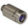 | こちらのファイバーコリメーターパッケージは、FC/PC、FC/APC、またはSMAコネクタ付きファイバからの出射光をコリメートするように、予めアライメントされています。各コリメーターパッケージは、405 nm~4.55 µmの波長で回折限界性能が得られるように工場で調整されています。設計波長以外でコリメータを使用することは可能ですが、色収差が生じるため最適な性能が得られるのは設計波長においてのみです。非球面レンズの実際の焦点距離は、色収差により波長に依存します。 |
| エアスペース型複レンズ、大径ビームコリメータ | 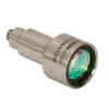 | 大径ビーム(Ø5.3 mm~Ø8.5 mm)用として、FC/PC、FC/APC、SMAコネクタ付きエアスペース型複レンズコリメータをご用意しています。こちらのコリメーターパッケージは、FCやSMAコネクタ付きファイバからの出射光をコリメートし、設計波長で回折限界性能が得られるように工場で予めアライメントされています。 |
| トリプレットレンズコリメータ | 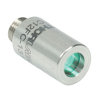 | 高品質なトリプレットコリメーターパッケージは、エアスペース型トリプレットレンズを使用しており、非球面レンズを用いたコリメータよりも優れたビーム品質が得られます。収差の小さいトリプレットを用いることの利点は、M2値として1(ガウシアン)に近い値が得られ、広がり角や波面エラーが小さくなることなどです。 |
| マルチモードファイバ用アクロマティックコリメータ |  | 高NAアクロマティックコリメータは、メニスカスレンズとアクロマティック複レンズを組み合わせることで、可視スペクトル域において球面収差の少ない優れた性能を発揮します。高NAのマルチモードファイバ用に設計されているため、オプトジェネティクスやファイバーフォトメトリの用途に適しています。 |
| 反射型コリメータ | 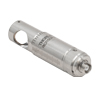 | 金属コーティング反射型コリメータは、90°軸外放物面(OAP)ミラーをベースにしています。レンズと違い、ミラーは広い波長範囲にわたり焦点距離が変化しません。この特性により、軸外放物面(OAP)ミラーを用いたコリメータは広い波長範囲に対応させるための調整が不要となるため、多色光を用いる用途に適しています。当社の反射型コリメータはシングルモードファイバからの光のコリメートには適していますが、シングルモードファイバへの結合には適していません。当社では、小型で当社の16 mmケージシステムに直接取付け可能な保護膜付き銀コーティングの反射型コリメータもご用意しております。 |
| FiberPort | 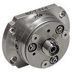 | こちらのコンパクトで極めて安定なFiberPortマイクロポジショナは、FC/PC、FC/APCまたはSMAコネクタ付き光ファイバとの光の入出射用として、安定で使いやすいプラットフォームです。シングルモード、マルチモードまたは偏波保持ファイバと組み合わせて使用することができ、ポスト、ステージ、プラットフォーム、レーザなどに取り付けることができます。組み込まれている非球面またはアクロマティックレンズのARコーティングは5種類から選択でき、また5軸のアライメント調整(3つの移動調整と2つの角度調整)が可能です。コンパクトでアライメントの長期安定性に優れたFiberPortは、ファイバへの光の結合、コリメート、組み込み用途(OEM用途)などに適しています。 |
| 調整可能型ファイバーコリメータ |  | このコリメータは、FC/PC、FC/APCまたはSMAコネクタに接続するよう設計されており、内部にはARコーティング付き非球面レンズが取付けられています。非球面レンズとファイバ先端との距離は、焦点距離の変化を補正したり、波長や対象までの距離に合わせて再コリメートしたりするために調整することができます。 |
| アクロマティックファイバーコリメータ、焦点調整可能 |  | 焦点調整の可能な当社のアクロマティックファイバーコリメータは、20 mm、40 mmまたは80 mmの有効焦点距離(EFL) を有し、その光学素子のARコーティングは3種類の広帯域ARコーティングから選ぶことができます。また、接続用コネクタの種類としては、FC/PC、FC/APCまたはSMA905をご用意しています。4枚のレンズを使用したエアスペース型設計であるため、非球面レンズのコリメータに比べてビーム品質に優れ(1に近いM2)、波面誤差は小さくなっています。これらのコリメータは自由空間光のファイバへの結合や、ファイバからの出射光のコリメートなどにご使用いただけます。また、距離をとって配置した2つのコリメータを用いて光を結合させると、光が2番目のコリメータに入る前にそのビームを操作することが可能になります。 |
| ズーム機能付きファイバーコリメータ | 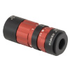 | こちらのコリメータは、ビームをコリメートしたまま、6~18 mmの範囲で焦点距離を変えることができます。そのため、コリメートした状態でビームサイズを変更できます。このデバイスは、用途に適した固定のファイバーコリメータを探す手間を省けるという利点に加え、1つで様々な幅広い用途に対応することができます。FC/PC、FC/APCまたはSMA905コネクタが付いており、反射防止コーティングは3種類からお選びいただけます。 |
| シングルモードファイバーピグテール付きコリメータ |  | シングルモードファイバーピグテール付きコリメータは、長さ1メートルのファイバとそれに対して予めアライメントされたARコーティング付き非球面レンズとで構成されており、532 nm、633 nm、780 nm、850 nm、1030 nm、1064 nm、1310 nm、1550 nmの8波長用の製品をご用意しています。コーティング波長域内のどの波長でもコリメートできますが、設計波長からずれると結合損失が増加します。 |
| 偏波保持ファイバーピグテール付きコリメータ | 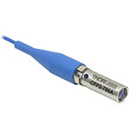 | 偏波保持ファイバーピグテール付きコリメータは、長さ1メートルのファイバとそれに対して予めアライメントされたARコーティング付き非球面レンズとで構成されており、633 nm、780 nm、980 nm、1064 nm、1550 nmの5波長用の製品をご用意しています。波長やコネクタについてはカスタム仕様も対応可能です。筐体の外側にはスロー軸と平行なラインが刻印されています。これは入射光の偏光面をアライメントする際の目安としてお使いいただけます。コーティング波長域内のどの波長でもコリメートできますが、設計波長からずれると結合損失が増加します。 |
| GRINレンズコリメータ | 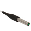 | GRINレンズファイバーコリメータは、630~1550 nmの範囲内の様々な波長に対してアライメントされた製品をご用意しており、FCまたはAPCコネクタ付きもしくはコネクタ無しのタイプからお選びいただけます。この有効径Ø1.8 mmのGRINレンズコリメータは、ファイバへの後方反射光を抑えるためにARコーティングが施されており、標準のシングルモードファイバまたはグレーデッドインデックス(GI)マルチモードファイバに結合されています。 |
| GRINレンズ |  | この屈折率分布型(GRIN)レンズは630 nm、830 nm、1060 nm、1300 nm、または1560 nmの波長用にARコーティングが施されており、光ファイバから出射した光が自由空間の光学系を通過して再度別のファイバに入射するまでの各用途にご利用いただけます。また半導体レーザの出射光のファイバへの結合、ファイバからの出射光のディテクタへの集光、レーザ光のコリメートなどにも適しています。このGRINレンズは当社の ピグテール付きガラスフェルールやGRINレンズ/フェルール用スリーブと組み合わせてお使いいただくこともできます。 |

有効焦点距離が≤7.5 mmのFiberPortは、FC/PCならびにFC/APCコネクタ両方にご使用いただけます。5軸調整機能に短い焦点距離を組み合わせた場合、軸外への出射光は無視できるレベルに調整可能です。
| Item # | EFL | Input MFDa,b | Output 1/e2 Waist Diametera | Max Waist Distancea,c | Divergencea | EFL Shiftd (Click for Plot) | Lens Characteristics | Length Lg | |||
|---|---|---|---|---|---|---|---|---|---|---|---|
| CAe | NA | AR Rangef | Material (Click for Plot) | ||||||||
| PAF2-A4A | 4.0 mm | 3.5 µm | 0.65 mm | 378 mm | 0.875 mrad | 1.8 mm | 0.22 | 350 - 700 nm | N-SK16 / N-LASF9 | 0.70" (17.7 mm) | |
| PAF2-A4B | 4.0 mm | 5.0 µm | 0.87 mm | 350 mm | 1.250 mrad | 1.8 mm | 0.22 | 600 - 1050 nm | N-LAK22 / N-SF6HT | 0.70" (17.7 mm) | |
| PAF2-A4C | 4.0 mm | 10.4 µm | 0.76 mm | 150 mm | 2.600 mrad | 1.8 mm | 0.22 | 1050 - 1620 nm | N-SF66 / N-LASF41 | 0.70" (17.7 mm) | |
| PAF2-A7A | 7.5 mm | 3.5 µm | 1.23 mm | 1323 mm | 0.467 mrad | 4.5 mm | 0.30 | 400 - 700 nm | N-BAF10 / N-SF6HT | 0.70" (17.7 mm) | |
| PAF2-A7B | 7.5 mm | 5.0 µm | 1.62 mm | 1225 mm | 0.667 mrad | 4.5 mm | 0.30 | 650 - 1050 nm | N-BAF10 / N-SF6HT | 0.70" (17.7 mm) | |
| PAF2-A7C | 7.5 mm | 10.4 µm | 1.42 mm | 521 mm | 1.387 mrad | 4.5 mm | 0.30 | 1050 - 1700 nm | N-LAK22 / N-SF6 | 0.70" (17.7 mm) | |

| Item # | EFL | Input MFDa,b | Output 1/e2 Waist Diametera | Max Waist Distancea,c | Divergencea | EFL Shiftd (Click for Plot) | Lens Characteristics | Length Lg | |||
|---|---|---|---|---|---|---|---|---|---|---|---|
| CAe | NA | AR Rangef | Material (Click for Plot) | ||||||||
| PAF2P-A10A | 10.0 mm | 3.5 µm | 1.64 mm | 2349 mm | 0.350 mrad | >4.5 mm | 0.23 | 400 - 700 nm | N-BAK4/SF5 | 0.87" (22.2 mm) | |
| PAF2P-A10B | 10.0 mm | 5.0 µm | 2.16 mm | 2175 mm | 0.500 mrad | >4.5 mm | 0.23 | 650 - 1050 nm | N-LAK22/N-SF6HT | 0.87" (22.2 mm) | |
| PAF2P-A10C | 10.0 mm | 10.4 µm | 1.99 mm | 922 mm | 0.990 mrad | >4.5 mm | 0.23 | 1050 - 1700 nm | N-LAK22/N-SF6 | 0.87" (22.2 mm) | |
| PAF2P-A15A | 15.0 mm | 3.5 µm | 2.46 mm | 5277 mm | 0.233 mrad | >4.5 mm | 0.15 | 400 - 700 nm | N-BK7/SF2 | 0.87" (22.2 mm) | |
| PAF2P-A15B | 15.0 mm | 5.0 µm | 3.25 mm | 4885 mm | 0.333 mrad | >4.5 mm | 0.15 | 650 - 1050 nm | N-LAK22/N-SF6HT | 0.87" (22.2 mm) | |
| PAF2P-A15C | 15.0 mm | 10.4 µm | 2.85 mm | 2068 mm | 0.693 mrad | >4.5 mm | 0.15 | 1050 - 1700 nm | N-BAF10/N-SF6 | 0.87" (22.2 mm) | |

| Item # | EFL | Input MFDa,b | Output 1/e2 Waist Diametera | Max Waist Distancea,c | Divergencea | EFL Shiftd (Click for Plot) | Lens Characteristics | Length Lg | |||
|---|---|---|---|---|---|---|---|---|---|---|---|
| CAe | NA | AR Rangef | Material (Click for Plot) | ||||||||
| PAF2A-A10A | 10.0 mm | 3.5 µm | 1.64 mm | 2349 mm | 0.350 mrad | >4.5 mm | 0.23 | 400 - 700 nm | N-BAK4/SF5 | 0.88" (22.4 mm) | |
| PAF2A-A10B | 10.0 mm | 5.0 µm | 2.16 mm | 2175 mm | 0.500 mrad | >4.5 mm | 0.23 | 650 - 1050 nm | N-LAK22/N-SF6HT | 0.88" (22.4 mm) | |
| PAF2A-A10C | 10.0 mm | 10.4 µm | 1.99 mm | 922 mm | 0.990 mrad | >4.5 mm | 0.23 | 1050 - 1700 nm | N-LAK22/N-SF6 | 0.88" (22.4 mm) | |
| PAF2A-A15A | 15.0 mm | 3.5 µm | 2.46 mm | 5277 mm | 0.233 mrad | >4.5 mm | 0.15 | 400 - 700 nm | N-BK7/SF2 | 0.88" (22.4 mm) | |
| PAF2A-A15B | 15.0 mm | 5.0 µm | 3.25 mm | 4885 mm | 0.333 mrad | >4.5 mm | 0.15 | 650 - 1050 nm | N-LAK22/N-SF6HT | 0.88" (22.4 mm) | |
| PAF2A-A15C | 15.0 mm | 10.4 µm | 2.85 mm | 2068 mm | 0.693 mrad | >4.5 mm | 0.15 | 1050 - 1700 nm | N-BAF10/N-SF6 | 0.88" (22.4 mm) | |

| Item # | EFL | Input MFDa,b | Output 1/e2 Waist Diametera | Max Waist Distancea,c | Divergencea | EFL Shiftd (Click for Plot) | Lens Characteristics | Length Lg | |||
|---|---|---|---|---|---|---|---|---|---|---|---|
| CAe | NA | AR Rangef | Material (Click for Plot) | ||||||||
| PAF2S-A4A | 4.0 mm | 3.5 µm | 0.65 mm | 378 mm | 0.875 mrad | 1.8 mm | 0.22 | 350 - 700 nm | N-SK16 / N-LASF9 | 0.87" (22.0 mm) | |
| PAF2S-A4B | 4.0 mm | 5.0 µm | 0.87 mm | 350 mm | 1.250 mrad | 1.8 mm | 0.22 | 600 - 1050 nm | N-LAK22 / N-SF6HT | 0.87" (22.0 mm) | |
| PAF2S-A4C | 4.0 mm | 10.4 µm | 0.76 mm | 150 mm | 2.600 mrad | 1.8 mm | 0.22 | 1050 - 1620 nm | N-SF66 / N-LASF41 | 0.87" (22.0 mm) | |
| PAF2S-A7A | 7.5 mm | 3.5 µm | 1.23 mm | 1323 mm | 0.467 mrad | 4.5 mm | 0.30 | 400 - 700 nm | N-BAF10 / N-SF6HT | 0.87" (22.0 mm) | |
| PAF2S-A7B | 7.5 mm | 5.0 µm | 1.62 mm | 1225 mm | 0.667 mrad | 4.5 mm | 0.30 | 650 - 1050 nm | N-BAF10 / N-SF6HT | 0.87" (22.0 mm) | |
| PAF2S-A7C | 7.5 mm | 10.4 µm | 1.42 mm | 521 mm | 1.387 mrad | 4.5 mm | 0.30 | 1050 - 1700 nm | N-LAK22 / N-SF6 | 0.87" (22.0 mm) | |

有効焦点距離が7.5 mm以下のFiberPortはFC/PCコネクタならびにFC/APCコネクタの両方にご使用いただけます。5軸調整機能に短い焦点距離を組み合わせた場合、軸外への出射光は無視できるレベルに調整可能です。
| Item # | EFL | Input MFDa,b | Output 1/e2 Waist Diametera | Max Waist Distancea,c | Divergencea | Lens Characteristics | Length Lf | |||
|---|---|---|---|---|---|---|---|---|---|---|
| CAd | NA | AR Rangee | Material | |||||||
| PAF2-2A | 2.0 mm | 3.5 µm | 0.33 mm | 96 mm | 1.750 mrad | 2.0 mm | 0.50 | 350 - 700 nm | ECO-550 | 0.70" (17.7 mm) |
| PAF2-2B | 2.0 mm | 5.0 µm | 0.43 mm | 89 mm | 2.500 mrad | 2.0 mm | 0.50 | 600 - 1050 nm | ECO-550 | 0.70" (17.7 mm) |
| PAF2-2C | 2.0 mm | 10.4 µm | 0.38 mm | 38 mm | 5.200 mrad | 2.0 mm | 0.50 | 1050 - 1620 nm | ECO-550 | 0.70" (17.7 mm) |
| PAF2-4E | 4.0 mm | 14.80 µm | 1.17 mm | 162 mm | 3.700 mrad | 5.0 mm | 0.56 | 2.0 - 5.0 µm | Black Diamond-2 | 0.70" (17.7 mm) |
| PAF2-5A | 4.6 mm | 3.5 µm | 0.75 mm | 499 mm | 0.761 mrad | 4.9 mm | 0.53 | 350 - 700 nm | H-LAK54 | 0.70" (17.7 mm) |
| PAF2-5B | 4.6 mm | 5.0 µm | 1.00 mm | 463 mm | 1.087 mrad | 4.9 mm | 0.53 | 600 - 1050 nm | H-LAK54 | 0.70" (17.7 mm) |
| PAF2-5C | 4.6 mm | 10.4 µm | 0.87 mm | 198 mm | 2.261 mrad | 4.9 mm | 0.53 | 1050 - 1620 nm | H-LAK54 | 0.70" (17.7 mm) |
| PAF2-5D | 4.6 mm | 13.0 µm | 0.90 mm | 164 mm | 2.826 mrad | 4.9 mm | 0.53 | 1.8 - 2.4 µm | H-LAK54 | 0.70" (17.7 mm) |
| PAF2-7A | 7.5 mm | 3.5 µm | 1.23 mm | 1323 mm | 0.467 mrad | 4.5 mm | 0.30 | 350 - 700 nm | H-LAK54 | 0.70" (17.7 mm) |
| PAF2-7B | 7.5 mm | 5.0 µm | 1.62 mm | 1225 mm | 0.667 mrad | 4.5 mm | 0.30 | 600 - 1050 nm | H-LAK54 | 0.70" (17.7 mm) |
| PAF2-7C | 7.5 mm | 10.4 µm | 1.42 mm | 521 mm | 1.387 mrad | 4.5 mm | 0.30 | 1050 - 1620 nm | H-LAK54 | 0.70" (17.7 mm) |

| Item # | EFL | Input MFDa,b | Output 1/e2 Waist Diametera | Max Waist Distancea,c | Divergencea | Lens Characteristics | Length Lf | |||
|---|---|---|---|---|---|---|---|---|---|---|
| CAd | NA | AR Rangee | Material | |||||||
| PAF2P-11A | 11.0 mm | 3.5 µm | 1.80 mm | 2841 mm | 0.318 mrad | 4.4 mm | 0.20 | 350 - 700 nm | H-LAK54 | 0.87" (22.0 mm) |
| PAF2P-11B | 11.0 mm | 5.0 µm | 2.38 mm | 2630 mm | 0.455 mrad | 4.4 mm | 0.20 | 600 - 1050 nm | H-LAK54 | 0.87" (22.0 mm) |
| PAF2P-11C | 11.0 mm | 10.4 µm | 2.09 mm | 1115 mm | 0.945 mrad | 4.4 mm | 0.20 | 1050 - 1620 nm | H-LAK54 | 0.87" (22.0 mm) |
| PAF2P-11D | 11.0 mm | 13.0 µm | 2.15 mm | 921 mm | 1.182 mrad | 4.4 mm | 0.20 | 1.8 - 2.4 µm | H-LAK54 | 0.87" (22.0 mm) |
| PAF2P-11E | 11.0 mm | 14.80 µm | 3.21 mm | 1203 mm | 1.345 mrad | 4.0 mm | 0.18 | 2.0 - 5.0 µm | Black Diamond-2 | 0.87" (22.0 mm) |
| PAF2P-15A | 15.3 mm | 3.5 µm | 2.52 mm | 5490 mm | 0.227 mrad | 5.0 mm | 0.16 | 350 - 700 nm | D-ZK3 | 0.87" (22.0 mm) |
| PAF2P-15B | 15.3 mm | 5.0 µm | 3.33 mm | 5082 mm | 0.325 mrad | 5.0 mm | 0.16 | 600 - 1050 nm | D-ZK3 | 0.87" (22.0 mm) |
| PAF2P-15C | 15.3 mm | 10.4 µm | 2.92 mm | 2151 mm | 0.675 mrad | 5.0 mm | 0.16 | 1050 - 1620 nm | D-ZK3 | 0.87" (22.0 mm) |
| PAF2P-15D | 15.3 mm | 13.0 µm | 3.00 mm | 1775 mm | 0.850 mrad | 5.0 mm | 0.16 | 1.8 - 2.4 µm | D-ZK3 | 0.87" (22.0 mm) |
| PAF2P-18A | 18.4 mm | 3.5 µm | 3.01 mm | 7936 mm | 0.190 mrad | 5.5 mm | 0.15 | 350 - 700 nm | D-ZK3 | 0.87" (22.0 mm) |
| PAF2P-18B | 18.4 mm | 5.0 µm | 3.98 mm | 7347 mm | 0.272 mrad | 5.5 mm | 0.15 | 600 - 1050 nm | D-ZK3 | 0.87" (22.0 mm) |
| PAF2P-18C | 18.4 mm | 10.4 µm | 3.49 mm | 3107 mm | 0.565 mrad | 5.5 mm | 0.15 | 1050 - 1620 nm | D-ZK3 | 0.87" (22.0 mm) |
| PAF2P-18D | 18.4 mm | 13.0 µm | 3.60 mm | 2564 mm | 0.707 mrad | 5.5 mm | 0.15 | 1.8 - 2.4 µm | D-ZK3 | 0.87" (22.0 mm) |

| Item # | EFL | Input MFDa,b | Output 1/e2 Waist Diametera | Max Waist Distancea,c | Divergencea | Lens Characteristics | Length Lf | |||
|---|---|---|---|---|---|---|---|---|---|---|
| CAd | NA | AR Rangee | Material | |||||||
| PAF2A-2A | 2.0 mm | 3.5 µm | 0.33 mm | 96 mm | 1.750 mrad | 2.0 mm | 0.50 | 350 - 700 nm | ECO-550 | 0.70" (17.9 mm) |
| PAF2A-2B | 2.0 mm | 5.0 µm | 0.43 mm | 89 mm | 2.500 mrad | 2.0 mm | 0.50 | 600 - 1050 nm | ECO-550 | 0.70" (17.9 mm) |
| PAF2A-2C | 2.0 mm | 10.4 µm | 0.38 mm | 38 mm | 5.200 mrad | 2.0 mm | 0.50 | 1050 - 1620 nm | ECO-550 | 0.70" (17.9 mm) |
| PAF2A-5A | 4.6 mm | 3.5 µm | 0.75 mm | 499 mm | 0.761 mrad | 4.9 mm | 0.53 | 350 - 700 nm | H-LAK54 | 0.70" (17.9 mm) |
| PAF2A-5B | 4.6 mm | 5.0 µm | 1.00 mm | 463 mm | 1.087 mrad | 4.9 mm | 0.53 | 600 - 1050 nm | H-LAK54 | 0.70" (17.9 mm) |
| PAF2A-5C | 4.6 mm | 10.4 µm | 0.87 mm | 198 mm | 2.261 mrad | 4.9 mm | 0.53 | 1050 - 1620 nm | H-LAK54 | 0.70" (17.9 mm) |
| PAF2A-7A | 7.5 mm | 3.5 µm | 1.23 mm | 1323 mm | 0.467 mrad | 4.5 mm | 0.30 | 350 - 700 nm | H-LAK54 | 0.70" (17.9 mm) |
| PAF2A-7B | 7.5 mm | 5.0 µm | 1.62 mm | 1225 mm | 0.667 mrad | 4.5 mm | 0.30 | 600 - 1050 nm | H-LAK54 | 0.70" (17.9 mm) |
| PAF2A-7C | 7.5 mm | 10.4 µm | 1.42 mm | 521 mm | 1.387 mrad | 4.5 mm | 0.30 | 1050 - 1620 nm | H-LAK54 | 0.70" (17.9 mm) |
| PAF2A-11A | 11.0 mm | 3.5 µm | 1.80 mm | 2841 mm | 0.318 mrad | 4.4 mm | 0.20 | 350 - 700 nm | H-LAK54 | 0.88" (22.4 mm) |
| PAF2A-11B | 11.0 mm | 5.0 µm | 2.38 mm | 2630 mm | 0.455 mrad | 4.4 mm | 0.20 | 600 - 1050 nm | H-LAK54 | 0.88" (22.4 mm) |
| PAF2A-11C | 11.0 mm | 10.4 µm | 2.09 mm | 1115 mm | 0.945 mrad | 4.4 mm | 0.20 | 1050 - 1620 nm | H-LAK54 | 0.88" (22.4 mm) |
| PAF2A-11D | 11.0 mm | 13.0 µm | 2.15 mm | 921 mm | 1.182 mrad | 4.4 mm | 0.20 | 1.8 - 2.4 µm | H-LAK54 | 0.88" (22.4 mm) |
| PAF2A-11E | 11.0 mm | 14.80 µm | 3.21 mm | 1203 mm | 1.345 mrad | 4.0 mm | 0.18 | 2.0 - 5.0 µm | Black Diamond-2 | 0.88" (22.4 mm) |
| PAF2A-15A | 15.3 mm | 3.5 µm | 2.52 mm | 5490 mm | 0.227 mrad | 5.0 mm | 0.16 | 350 - 700 nm | D-ZK3 | 0.88" (22.4 mm) |
| PAF2A-15B | 15.3 mm | 5.0 µm | 3.33 mm | 5082 mm | 0.325 mrad | 5.0 mm | 0.16 | 600 - 1050 nm | D-ZK3 | 0.88" (22.4 mm) |
| PAF2A-15C | 15.3 mm | 10.4 µm | 2.92 mm | 2151 mm | 0.675 mrad | 5.0 mm | 0.16 | 1050 - 1620 nm | D-ZK3 | 0.88" (22.4 mm) |
| PAF2A-15D | 15.3 mm | 13.0 µm | 3.00 mm | 1775 mm | 0.850 mrad | 5.0 mm | 0.16 | 1.8 - 2.4 µm | D-ZK3 | 0.88" (22.4 mm) |
| PAF2A-18A | 18.4 mm | 3.5 µm | 3.01 mm | 7936 mm | 0.190 mrad | 5.5 mm | 0.15 | 350 - 700 nm | D-ZK3 | 0.88" (22.4 mm) |
| PAF2A-18B | 18.4 mm | 5.0 µm | 3.98 mm | 7347 mm | 0.272 mrad | 5.5 mm | 0.15 | 600 - 1050 nm | D-ZK3 | 0.88" (22.4 mm) |
| PAF2A-18C | 18.4 mm | 10.4 µm | 3.49 mm | 3107 mm | 0.565 mrad | 5.5 mm | 0.15 | 1050 - 1620 nm | D-ZK3 | 0.88" (22.4 mm) |
| PAF2A-18D | 18.4 mm | 13.0 µm | 3.60 mm | 2564 mm | 0.707 mrad | 5.5 mm | 0.15 | 1.8 - 2.4 µm | D-ZK3 | 0.88" (22.4 mm) |

| Item # | EFL | Input MFDa,b | Output 1/e2 Waist Diametera | Max Waist Distancea,c | Divergencea | Lens Characteristics | Length Lf | |||
|---|---|---|---|---|---|---|---|---|---|---|
| CAd | NA | AR Rangee | Material | |||||||
| PAF2S-2A | 2.0 mm | 3.5 µm | 0.33 mm | 96 mm | 1.750 mrad | 2.0 mm | 0.50 | 350 - 700 nm | ECO-550 | 0.87" (22.0 mm) |
| PAF2S-2B | 2.0 mm | 5.0 µm | 0.43 mm | 89 mm | 2.500 mrad | 2.0 mm | 0.50 | 600 - 1050 nm | ECO-550 | 0.87" (22.0 mm) |
| PAF2S-2C | 2.0 mm | 10.4 µm | 0.38 mm | 38 mm | 5.200 mrad | 2.0 mm | 0.50 | 1050 - 1620 nm | ECO-550 | 0.87" (22.0 mm) |
| PAF2S-4E | 4.0 mm | 14.80 µm | 1.17 mm | 162 mm | 3.700 mrad | 5.0 mm | 0.56 | 2.0 - 5.0 µm | Black Diamond-2 | 0.87" (22.0 mm) |
| PAF2S-5A | 4.6 mm | 3.5 µm | 0.75 mm | 499 mm | 0.761 mrad | 4.9 mm | 0.53 | 350 - 700 nm | H-LAK54 | 0.87" (22.0 mm) |
| PAF2S-5B | 4.6 mm | 5.0 µm | 1.00 mm | 463 mm | 1.087 mrad | 4.9 mm | 0.53 | 600 - 1050 nm | H-LAK54 | 0.87" (22.0 mm) |
| PAF2S-5C | 4.6 mm | 10.4 µm | 0.87 mm | 198 mm | 2.261 mrad | 4.9 mm | 0.53 | 1050 - 1620 nm | H-LAK54 | 0.87" (22.0 mm) |
| PAF2S-5D | 4.6 mm | 13.0 µm | 0.90 mm | 164 mm | 2.826 mrad | 4.9 mm | 0.53 | 1.8 - 2.4 µm | H-LAK54 | 0.87" (22.0 mm) |
| PAF2S-7A | 7.5 mm | 3.5 µm | 1.23 mm | 1323 mm | 0.467 mrad | 4.5 mm | 0.30 | 350 - 700 nm | H-LAK54 | 0.87" (22.0 mm) |
| PAF2S-7B | 7.5 mm | 5.0 µm | 1.62 mm | 1225 mm | 0.667 mrad | 4.5 mm | 0.30 | 600 - 1050 nm | H-LAK54 | 0.87" (22.0 mm) |
| PAF2S-7C | 7.5 mm | 10.4 µm | 1.42 mm | 521 mm | 1.387 mrad | 4.5 mm | 0.30 | 1050 - 1620 nm | H-LAK54 | 0.87" (22.0 mm) |
| PAF2S-11A | 11.0 mm | 3.5 µm | 1.80 mm | 2841 mm | 0.318 mrad | 4.4 mm | 0.20 | 350 - 700 nm | H-LAK54 | 1.04" (26.5 mm) |
| PAF2S-11B | 11.0 mm | 5.0 µm | 2.38 mm | 2630 mm | 0.455 mrad | 4.4 mm | 0.20 | 600 - 1050 nm | H-LAK54 | 1.04" (26.5 mm) |
| PAF2S-11C | 11.0 mm | 10.4 µm | 2.09 mm | 1115 mm | 0.945 mrad | 4.4 mm | 0.20 | 1050 - 1620 nm | H-LAK54 | 1.04" (26.5 mm) |
| PAF2S-11D | 11.0 mm | 13.0 µm | 2.15 mm | 921 mm | 1.182 mrad | 4.4 mm | 0.20 | 1.8 - 2.4 µm | H-LAK54 | 1.04" (26.5 mm) |
| PAF2S-11E | 11.0 mm | 14.80 µm | 3.21 mm | 1203 mm | 1.345 mrad | 4.0 mm | 0.18 | 2.0 - 5.0 µm | Black Diamond-2 | 1.04" (26.5 mm) |
| PAF2S-15A | 15.3 mm | 3.5 µm | 2.52 mm | 5490 mm | 0.227 mrad | 5.0 mm | 0.16 | 350 - 700 nm | D-ZK3 | 1.04" (26.5 mm) |
| PAF2S-15B | 15.3 mm | 5.0 µm | 3.33 mm | 5082 mm | 0.325 mrad | 5.0 mm | 0.16 | 600 - 1050 nm | D-ZK3 | 1.04" (26.5 mm) |
| PAF2S-15C | 15.3 mm | 10.4 µm | 2.92 mm | 2151 mm | 0.675 mrad | 5.0 mm | 0.16 | 1050 - 1620 nm | D-ZK3 | 1.04" (26.5 mm) |
| PAF2S-15D | 15.3 mm | 13.0 µm | 3.00 mm | 1775 mm | 0.850 mrad | 5.0 mm | 0.16 | 1.8 - 2.4 µm | D-ZK3 | 1.04" (26.5 mm) |
| PAF2S-18A | 18.4 mm | 3.5 µm | 3.01 mm | 7936 mm | 0.190 mrad | 5.5 mm | 0.15 | 350 - 700 nm | D-ZK3 | 1.04" (26.5 mm) |
| PAF2S-18B | 18.4 mm | 5.0 µm | 3.98 mm | 7347 mm | 0.272 mrad | 5.5 mm | 0.15 | 600 - 1050 nm | D-ZK3 | 1.04" (26.5 mm) |
| PAF2S-18C | 18.4 mm | 10.4 µm | 3.49 mm | 3107 mm | 0.565 mrad | 5.5 mm | 0.15 | 1050 - 1620 nm | D-ZK3 | 1.04" (26.5 mm) |
| PAF2S-18D | 18.4 mm | 13.0 µm | 3.60 mm | 2564 mm | 0.707 mrad | 5.5 mm | 0.15 | 1.8 - 2.4 µm | D-ZK3 | 1.04" (26.5 mm) |
 Products Home


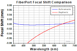
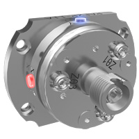


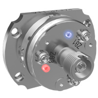
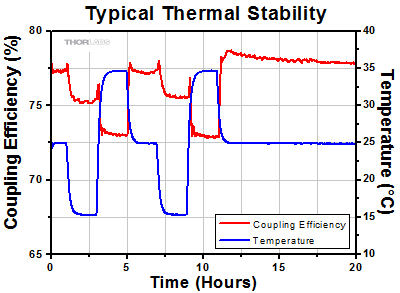 Click to Enlarge
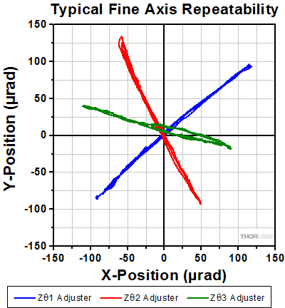


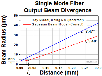
 FiberPortコリメータ/カプラ