FC/PCコリメーター(非球面レンズ)、焦点調整可能

- Collimate Light Exiting FC/PC-Terminated Fiber
- Low Beam Pointing Error During Adjustment
- Diffraction-Limited Performance
- Available Focal Lengths: 2.0 mm, 4.6 mm, 7.5 mm, and 11.0 mm
CFC5-A
f = 4.6 mm,
350 - 700 nm
(Back View)
CFC11P-B
f = 11.0 mm,
650 - 1050 nm
(Front View)
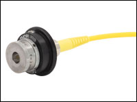
Adjustable Aspheric Collimator with an FC/PC Receptacle
CFC2-C
f = 2.0 mm,
1050 - 1700 nm
(Front View)

Please Wait
改良点
当社では、性能向上を目指して、こちらの焦点調整可能なファイバーコリメータを再設計しました。以下の点が改善されています。
- 寸法公差をより厳しくして、ポインティングの安定性を向上
- カスタム仕様のネジ加工により、より正確で精密な位置決めを実現
- ロック用止めネジよりも均等に力を加えられるロッキングリングを採用
- レンズセルの安定化
特長
- ファイバからの光を自由空間にコリメート光として出射
- 焦点距離は4種類:2.0 mm、4.6 mm、7.5 mm、11.0 mm
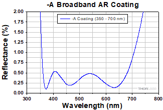
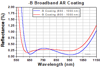
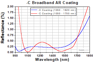
- 非球面レンズのARコーティングは3種類ご用意
- 350~700 nm
- 650~1050 nm(CFC2-Bは600~1050 nm)
- 1050~1620 nm(CFC2-Cは1050~1700 nm)
- FC/PCレセプタクル、2.1 mmワイドキー
- 対応するコネクタ(下表参照)の使用により回折限界性能
- 調整時のポインティング誤差:< 15 mrad
当社の焦点調整可能なFC/PCコリメータは、ステンレススチール製のセル内にARコーティング付き非球面レンズがバネで固定されて組立てられています。これらはファイバから出射される光をコリメートするように設計された製品であるため、ファイバ同士を結合する場合には当社のFiberPortあるいはファイバ入射型ナノポジショニングステージのご使用をお勧めいたします。
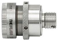
コリメータの外側バレルを回転させると、筐体内に取り付けられた非球面レンズは回転せずに光軸に沿って移動するため、レンズとファイバ先端の間の距離を調整することができます(この距離は下表の「Fiber-to-Lens Distance」でご覧いただけます)。左下の写真に見えるネジ部分の黒い帯は、外側バレルの推奨移動範囲の末端を示しており、この位置を超えて移動すると性能は保証された値よりも低下します。所定の位置にセットしたら、筐体の外側のローレット加工付きロッキングリングで固定できます。使用方法については右の動画をご覧ください。
こちらのコリメータは非回転のレンズセルを使用しており、また調整機構はビームポインティング誤差を最小化するように設計されています。ポインティングの安定性は、焦点距離が2.0 mmのコリメータでは15 mrad以下、焦点距離が4.6 mmと7.5 mmのコリメータでは5 mrad以下、11.0 mmのコリメータでは1 mrad以下です。仕様の詳細は下の各表をご覧ください。
こちらの焦点調整可能なコリメータは、当社のARコーティング付きシングルモードファイバーパッチケーブルと組み合わせてご使用になることをお勧めいたします。これらのケーブルでは、透過率を向上させるとともに、ファイバと自由空間の接続面における反射損失を低減するために、ファイバの片端に反射防止コーティングが施されています。代わりに、当社の様々な標準品のファイバーパッチケーブルから選んでご利用いただくことも可能です。
コリメータは、下の写真に示すように筐体のØ15 mmの部分をコリメータ用アダプタAD15F2に固定することで、取り付けられるようになります。アダプタのSM1外ネジを利用すると、当社の様々なSM1ネジ付きオプトメカニクス部品に組み込むことができます。
Click to Enlarge
焦点調整可能なコリメータのネジ部分に黒い帯が見えますが、これはコリメータの仕様として定められた調整範囲の限界を示しています。この範囲を超えると、ポインティングの安定性やその他の仕様は保証されません。
| New Item # Prefixa | New Pointing Stability | Former-Generation Item # Prefixa | Former-Generation Pointing Stability |
|---|---|---|---|
| CFC2 | < 15 mrad | CFC-2X | > 50 mrad (Typ.) |
| CFC5 | < 5 mrad | CFC-5X | > 15 mrad (Typ.) |
| CFC8 | < 5 mrad | CFC-8X | > 7 mrad (Typ.) |
| CFC11P | < 1 mrad | CFC-11X | > 2 mrad (Typ.) |
ポインティングの安定性の向上
当社の調整可能ファイバーコリメータは、ビームポインティング誤差を最小にするために設計を改良しました。寸法公差を慎重に調整することで、右の表のとおり、ポインティングの安定性を大幅に改善することができました。標準的な金属同士の接触点は、時間がたつにつれ摩耗します。当社ではこの影響を最小にし、長期にわたる安定性が保証できるよう、かじりに対して耐性のある材料を選択ています。 また、自社の機械加工設備により、高分解能、優れた偏心、最小限のバックラッシュとなるような特殊なアジャスターネジを特別製造しています。そして、調整中にピッチ・ヨーの動きを防ぐためにレンズセルを固定しています。
ヒステリシスの改善
旧世代の調整可能ファイバーコリメータには、外側バレルの位置とレンズ位置の固定にロック用止めネジを使用していました。この設計ではレンズセルに不要な横からの力が加わり、ミスアライメントならびにより大きいポインティング誤差をもたらしていました。新しいコリメータは回転バレル全体に渡り均一な力を加えるロッキングリングを使用しているため、ビームポインティングの安定性が保たれます。
下のグラフは、当社の調整可能ファイバーコリメータの非球面レンズに施されているARコーティングの反射率の波長特性を示しています。反射率は1面当たりの値です。
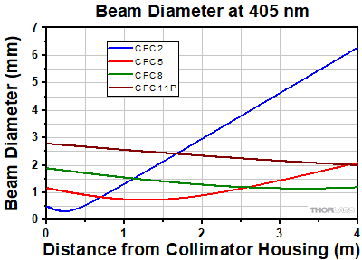
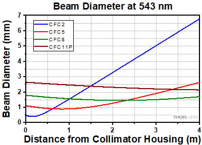
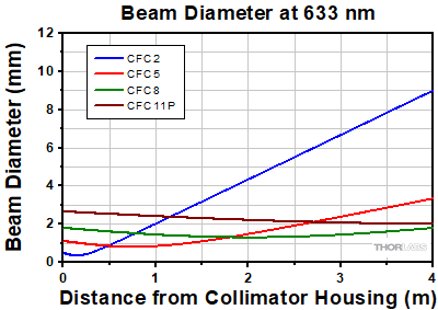
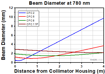
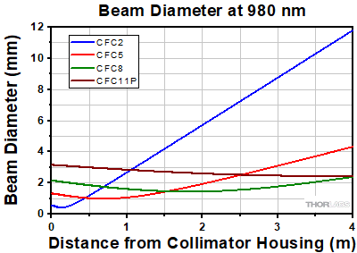
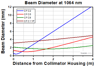
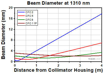
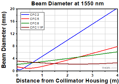
下のグラフは、当社の調整機能付きファイバーコリメータに記載された波長の光を入射し、広がり角が最小になるように調整したときの1/e2 ビーム径(理論値)を、伝搬距離の関数として示しています。なお、ビーム径は焦点距離やNAといった非球面レンズの特性に依存しますが、ARコーティングには影響されません。
ビームの広がり角の理論的近似値
仕様表に記載されているビームの広がり角(全角)は、ファイバーコリメータについて計算された理論値です。この広がり角の理論的近似値は、ファイバからの光がガウス型の強度プロファイルを有する場合、下記の計算式により簡単に求めることができます。この計算式は、シングルモードファイバの場合にはよく当てはまりますが、非ガウス型の強度プロファイルの光を出射するマルチモードファイバの場合には実際よりも小さい数値を与えます。
広がり角(全角、単位は°)は以下の式で求められます。

ここでMFDはモードフィールド径、fはコリメータの焦点距離です(注:この式ではMFDとfに同じ単位を使わなければなりません)。
例:
コリメータCFC2-A (f = 2.0 mm)とシングルモードファイバーパッチケーブルP1-460B-FC-2 (488 nmでMFD = 2.8~4.1 µm)を組み合わせて用いた場合を例にしてみます。ここでMFDとしてその平均値(3.5 µm)を使用すると、広がり角は
θ ≈ (0.0035 mm / 2.0 mm) * (180/3.1416) ≈ 0.100° または 1.75 mradとなります。
出射ビーム径の理論的近似値
出射ビーム径の近似値は以下の式で求められます。

ここでλは光の波長、MFDはモードフィールド径、fはコリメータの焦点距離です。
例:
コリメータCFC5-C (f = 4.6 mm)とパッチケーブルP1-SMF28E-FC-1(平均MFD = 10.4 µm)を組み合わせて1550 nmの光を使用した場合、その出射ビーム径は
4 * (1550 nm) * [4.6 mm / (π · 10.4 µm)] = 0.87 mmとなります。
ビームウェストまでの最大距離の理論的近似値
ビームウェスト最大距離、すなわちコリメーションを維持できるレンズからビームウェストまでの最大距離は、以下の式で近似値が求められます。

ここでfはコリメータの焦点距離、λは光の波長、MFDはモードフィールド径です。
例:
コリメータCFC2-A (f = 2.0 mm)とシングルモードファイバーパッチケーブルP1-460B-FC-2 (488 nmでMFD = 2.8~4.1 µm)を組み合わせて用いた場合を例にしてみます。MFDとしてその平均値(3.5 µm)を使用すると、波長488 nmにおけるビームウェストまでの最大距離は
(2 mm) + (2 * (2 mm)2 * (488 nm) / (3.1416) * (3.5 µm)2) = 103 mmとなります。
Insights:ビーム解析
こちらのページでは下記について説明しています。
- チョッパーホイールを使用したビームサイズ測定
このほかにも実験・実習や機器に関するヒントをまとめて掲載しています。こちらからご覧ください。
チョッパーホイールを使用したビームサイズ測定
Click to Enlarge
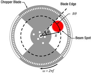
図2:ブレードは fの角回転速度で、Rθ の弧(Rはブレード中心からの距離)をトレースします。図のチョッパーホイールは、MC1F2です。
Click to Enlarge
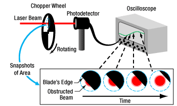
図1:上記に示すセットアップでおおよそのビームサイズの測定が可能です。チョッパーホイールのブレードがビームを横切るとき、S字状の曲線がオシロスコープに現れます。
Click to Enlarge
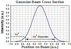
図4:ガウシアンビームの直径は1/e2強度の幅で表されます。
Click to Enlarge
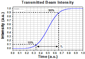
図3:信号の立ち上がり時間(tr )は、通常、強度の10%~90%の時間で定義されます。立ち上がり時間はホイールの回転速度とビーム径に依存します。
カメラや走査スリット型ビームプロファイラはビームサイズやビーム形状を特性化するツールですが、ビームサイズが小さすぎたり、動作範囲外の波長においては正確な測定を行うことができません。
ビームサイズの正確な測定にはチョッパーホイールやフォトディテクタ、オシロスコープが使用されます(図1)。回転するチョッパーホイールがビームを通過すると、S字状の軌跡がオシロスコープに表示されます。
ブレードがθ の角度を掃引すると、S曲線の立ち上がりまたは立ち下がり時間は、ブレードの移動方向に沿ったビームのサイズに比例します(図2)。 ホイールの中心からR の距離にあるブレードエッジ上の点は、ビームサイズにほぼ等しい弧の長さ分(Rθ )、ビームを横切ります。
このビームサイズ測定をするためには、ディテクタとオシロスコープを合わせた応答を、信号の変化の速度よりもはるかに速くする必要があります。
例:S曲線の立ち上がりエッジ
ビームに関連する角度 ftr )
ftr ) ftr )
ftr )

10%~90%の強度間で定義されたビーム径の1.56倍となります。
最終更新日:2021年6月22日
Content improved by our readers!
| Posted Comments: | |
user
(posted 2023-04-14 12:12:55.423) Hi, is it possible to know the exact model of the aspheric lens mounted in the collimator CFC11A-B? jgreschler
(posted 2023-04-14 08:23:49.0) Thank you for reaching out to Thorlabs. Component information is available by reaching out to techsupport@thorlabs.com. I have contacted you directly to provide the lens part number. Boerge Hemmerling
(posted 2023-04-04 18:03:49.857) Hi,
what is the power damager threshold for these collimators, e.g. CFC2-A?
We have a 30W fiber laser that I would like to connect to this type of collimator.
Thank you. cdolbashian
(posted 2023-04-13 11:10:31.0) Thank you for reaching out to us with this inquiry. Damage of optical coatings depends on the power density at the surface of the optic. We generally spec that the -A coating can handle up to 500W/cm linear power density. That being said, we would need to know the fiber you are using to properly estimate whether or not your component would be damaged. I have reached out to you directly to discuss this. Matias Berasategui
(posted 2023-04-03 07:14:57.59) Hello,
I would like to ask for a formal quote for product CFC5A-B.
Thank you,
Matias Berasategui. jgreschler
(posted 2023-04-03 08:33:07.0) Thank you for reaching out to Thorlabs. Formal quotes for stock items can be requested by emailing sales@thorlabs.com. I have arranged for one to be sent to your provided email address. charleshicks charleshicksBM
(posted 2022-09-22 00:45:51.397) cilong zhang
(posted 2022-03-13 12:50:10.93) Hi, I've got CFC2A, when distance get closer, the divergence of light get smaller, but even if set the closest distance, the light still divergent. Can you give me some advice, my laser wavelenght is 488nm(FC/APC) cdolbashian
(posted 2022-03-25 11:56:18.0) Thank you for reaching out to us with this inquiry. This type of feedback is hard to address without some more specific details regarding the fiber you are using and the effect you are observing. I have reached out to you directly to better understand the conditions under which you are implementing your component. Carl Thomas
(posted 2022-03-06 12:38:20.67) Hi-
I am hoping you can help me select the best fiber collimator for my application.
I would like to fiber couple 2 wavelengths (650 nm and 493 nm, both ~2mm spot size at input to collimator and merged on a dichroic before the collimator) into a APC s460HP fiber. Based on this, I believe the CFC11A-A collimator would be the best choice. Is this correct?
If I select this collimator, I will only be able to optimize the apsheric lens position for a single wavelength due to the focal shift. Can you recommend an appropriate second lens and position to place in one of the beam paths to compensate for the focal shift and optimize coupling for both wavelengths? Thanks cdolbashian
(posted 2022-03-15 10:54:43.0) Thank you for reaching out to us Carl. What you are looking to construct is an achromatic coupler/collimator. Using the information you provided, there would be ~200um focal shift between the two wavelengths provided, assuming all other conditions are identical. It is nontrivial to add just a single element optic in the optical path to make the focal point of both of these wavelength coincide at a single point for optimal coupling. Since you are already intending to use the adjustable focus collimator, you should be able to find a good position for coupling, then subsequently adjust the z-position of the collimator when changing wavelengths. I have reached out to you directly to discuss this further. user
(posted 2021-12-06 18:00:05.237) It would be nice to have APC fiber compatibility for focal lengths of less than f = 11 mm. The old collimators used to be APC compatible, and I'm disappointed to see this change. YLohia
(posted 2021-12-07 10:55:52.0) Hello, thank you for your feedback. We are in the process of releasing additional focal lengths (2mm, 5mm, and 8mm -- subject to change) in the line for APC connectors and hope to release it by Q1 2022. Andrew Davies
(posted 2020-08-06 01:57:49.34) Can I get a Zemax file for CFC11A-B? A black box lens would work. I want to get an idea of the chromatic aberration in my system. nbayconich
(posted 2020-08-07 05:14:46.0) Thank you for contacting Thorlabs. I will reach out to you directly to share the zemax file of the lens used in this collimation package. user
(posted 2020-04-24 17:43:34.267) Do you have any further information on the lens used -- i.e. which model does it correspond to exactly and the focal length shift with wavelength? YLohia
(posted 2020-04-27 09:36:20.0) Hello again, the CFC5 uses our A390 asphere. The focal length shift vs wavelength information can be found here : https://www.thorlabs.com/images/TabImages/A390_Asph.pdf user
(posted 2020-04-24 15:07:37.373) Hi, what material is the aspheric lens made of? YLohia
(posted 2020-04-24 04:41:37.0) Hello, thank you for contacting Thorlabs. The lens in CFC5-C is made of H-LAK54. sarmad albanna
(posted 2020-04-16 13:57:43.413) Hi there,
I am interested in this collimator but i am not clear on :
q1:if it is one device that can change the focal length using the barrel and the locking barrel from f=11 mm down to 2 mm? if so then why there are multiple devices?
q2: do you have the same device but instead of the manual adjustment of the focal length its electronic? please let me know asap Many thanks, Sarmad YLohia
(posted 2020-04-16 03:22:09.0) Hello Sarmad, thank you for contacting Thorlabs. The device does not change the focal length of the lens (this is a fixed quantity) -- instead, it allows for the adjustment of the focus, which is the distance between the lens and the fiber tip. Unfortunately, we currently do not offer a motorized focus adjuster for collimation lenses. For a motorized alternative, you may use our NanoMax (for example the MAX383) series of stages and supply your own fixed focal length aspheric lens. luis.pascual
(posted 2017-07-03 08:51:19.5) Regarding the CFC-5X-A collimator head. Could you please indicate me the allowed thermal range (for survival and for performances)?
Thank you and best regards tfrisch
(posted 2017-08-03 03:07:44.0) Hello, thank you for contacting Thorlabs. These collimators would not be damaged as high as 75°C, but there would likely be thermal expansion compared to alignment at room temperature. I see you have already been in contact with Tech Support concerning the specifics of your application. user
(posted 2017-06-19 15:38:34.617) Hi,
Looking at the calculations for the theoretical output beam diameter, I was wondering you take the FWHM, sigma or 1/e^2 as the diameter of the beam. tfrisch
(posted 2017-06-27 09:38:19.0) Hello, thank you for contacting Thorlabs. The beam diameter is given as 1/e^2. benalunda10
(posted 2017-06-15 11:49:31.453) We recently bought two products from you, LP405-SF10 and LDM9LP. You currently provide a collimation package F671FC-405 which has a beam diameter of omly 0.63 mm. We however need a collimation package that can give us a beam diameter of 1.4 mm. We have considered using an adjustable aspheric FC collimator CFC-8X-A.
By using the adjustable aspheric lens, are we able to collect all the power given the larger focal length on 7.23 mm?
What are we likely to loose by using the CFC-8X-A?
Please let us know if we can get a similar performance as when using F671FC-405. tfrisch
(posted 2017-06-27 08:32:30.0) Hello, thank you for contacting Thorlabs. It looks like you have already been in contact with our Tech Support Team about how CFC are single lens systems and as such, there is one position for which the output is collimated. This adjustment is intended to help adjust for chromatic focal shift of the lens used with different wavelengths. In order to achieve a larger diameter collimated output, a longer focal length lens should be used. nheer2
(posted 2016-04-28 11:55:45.263) by referring to the equipment here as "Adjustable" do we here mean that the diameter of the collimated beam coming out of the collimator is continuously adjustable? if yes what is the range for these diameter values and if no what do you refer to as adjustable? besembeson
(posted 2016-04-28 02:16:17.0) Response from Bweh at Thorlabs USA: By adjustable, we mean the lens housing is designed such that the lens position relative to the fiber tip can be adjusted to optimize beam collimation for different wavelengths over the AR coated spectrum. If you are looking for adjustable beam diameter collimation packages, we have these at the following page: http://www.thorlabs.com/newgrouppage9.cfm?objectgroup_ID=8642 yuns.jeon
(posted 2014-12-04 03:10:52.44) I reviewed the lens element in the CFC-5X-B. It turned out that its back focal length is 2.79 mm. But the adjustable range of the CFC-5X-B is 4.4~6.1, which is far away from the calculated number. Could you advice me in use of CFC-5X-B with corning fiber PM850 in the purpose of collimation. jlow
(posted 2014-12-12 09:22:10.0) Response from Jeremy at Thorlabs: Thank you for your feedback. The 4.4-6.1mm distance is referenced to the principal plane inside the lens. We will update the website to make the presentation clearer. shizg
(posted 2014-04-29 10:03:55.927) 请问这款可调焦准直器是否电动,另外调焦范围有多大? jlow
(posted 2014-04-29 08:17:20.0) Response from Jeremy at Thorlabs: We do not have a motorized version of the CFC series at the moment. You can find the adjustment range in the column "Fiber-to-Lens Distance", given in the table on each subgroup. bdada
(posted 2012-03-01 14:25:00.0) Response from Buki at Thorlabs:
The M18L01 patch cable uses the AFS105/125Y fiber, which has a 105um core diameter. Using ray optics for multimode fiber, you would get:
Beam Diameter (mm)= 2 x f (mm) x NA (fiber)
For example, with CFC-5X-C, the output beam diameter is approximately 0.87mm (refer to the "Calculations" tab on our website for details)
However, with the 105um core multimode fiber, the approximate beam diameter would be 2mm (2 x 4.6mm x 0.22). This is more than twice the expected beam diamter of the collimated beam when using a single mode fiber.
Please contact TechSupport@thorlabs.com if you have any questions. bdada
(posted 2012-02-13 15:12:00.0) Response from Buki at Thorlabs to aleksander.budnicki:
Thank you for your interest in the CFC-8X-B. We have contacted you to provide more information. aleksander.budnicki
(posted 2012-02-13 13:44:30.0) I've got one question regarding CFC-8x-B fiber collimator. Could you be as kind as possible an provide me the tolerance of dimensions, I have already downloaded some drawings but no information about.
Thanks in Advance,
Aleksander Budnicki Pontusw
(posted 2012-01-05 04:18:43.0) How much, aproximately, would the result in calculating divergence, beam width and Max Waist Distance change if a step index multimode fibre (M18L01) is used? user
(posted 2011-12-08 15:03:46.0) A response from Tyler at Thorlabs: Using gaussian beam propogation formulas the max waist distance is the maximum theoretical distance that the beam waist can be from the collimation lens. The wavefront of the collimated beam is flat at the beam waist. user
(posted 2011-12-07 11:02:01.0) Hi, can you please clarify the calculation behind the Max Waist Distance? Thanks. Thorlabs
(posted 2010-08-03 11:59:04.0) Response from Javier at Thorlabs to day: Thank you for your feedback. The CFC-8X-C is compatible with both FC/PC and FC/APC connectors. The reason is that the short distance between the tip of the connector and the lens makes the angular deviation negligible. day
(posted 2010-08-03 09:49:40.0) For the CFC-8X-C, do we need to specify the connector: FC/APC? |
ファイバーコリメーターセレクションガイド
コリメータの種類または画像をクリックすると、各コリメータの詳細がご覧いただけます。
| Type | Description | |
|---|---|---|
| 焦点固定型FC、APC、SMAファイバーコリメータ | 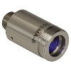 | こちらのファイバーコリメーターパッケージは、FC/PC、FC/APC、またはSMAコネクタ付きファイバからの出射光をコリメートするように、予めアライメントされています。各コリメーターパッケージは、405 nm~4.55 µmの波長で回折限界性能が得られるように工場で調整されています。設計波長以外でコリメータを使用することは可能ですが、色収差が生じるため最適な性能が得られるのは設計波長においてのみです。非球面レンズの実際の焦点距離は、色収差により波長に依存します。 |
| エアスペース型複レンズ、大径ビームコリメータ | 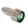 | 大径ビーム(Ø5.3 mm~Ø8.5 mm)用として、FC/PC、FC/APC、SMAコネクタ付きエアスペース型複レンズコリメータをご用意しています。こちらのコリメーターパッケージは、FCやSMAコネクタ付きファイバからの出射光をコリメートし、設計波長で回折限界性能が得られるように工場で予めアライメントされています。 |
| トリプレットレンズコリメータ | 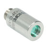 | 高品質なトリプレットコリメーターパッケージは、エアスペース型トリプレットレンズを使用しており、非球面レンズを用いたコリメータよりも優れたビーム品質が得られます。収差の小さいトリプレットを用いることの利点は、M2値として1(ガウシアン)に近い値が得られ、広がり角や波面エラーが小さくなることなどです。 |
| マルチモードファイバ用アクロマティックコリメータ | 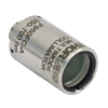 | 高NAアクロマティックコリメータは、メニスカスレンズとアクロマティック複レンズを組み合わせることで、可視スペクトル域において球面収差の少ない優れた性能を発揮します。高NAのマルチモードファイバ用に設計されているため、オプトジェネティクスやファイバーフォトメトリの用途に適しています。 |
| 反射型コリメータ | 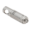 | 金属コーティング反射型コリメータは、90°軸外放物面(OAP)ミラーをベースにしています。レンズと違い、ミラーは広い波長範囲にわたり焦点距離が変化しません。この特性により、軸外放物面(OAP)ミラーを用いたコリメータは広い波長範囲に対応させるための調整が不要となるため、多色光を用いる用途に適しています。当社の反射型コリメータはシングルモードファイバからの光のコリメートには適していますが、シングルモードファイバへの結合には適していません。当社では、小型で当社の16 mmケージシステムに直接取付け可能な保護膜付き銀コーティングの反射型コリメータもご用意しております。 |
| FiberPort | 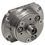 | こちらのコンパクトで極めて安定なFiberPortマイクロポジショナは、FC/PC、FC/APCまたはSMAコネクタ付き光ファイバとの光の入出射用として、安定で使いやすいプラットフォームです。シングルモード、マルチモードまたは偏波保持ファイバと組み合わせて使用することができ、ポスト、ステージ、プラットフォーム、レーザなどに取り付けることができます。組み込まれている非球面またはアクロマティックレンズのARコーティングは5種類から選択でき、また5軸のアライメント調整(3つの移動調整と2つの角度調整)が可能です。コンパクトでアライメントの長期安定性に優れたFiberPortは、ファイバへの光の結合、コリメート、組み込み用途(OEM用途)などに適しています。 |
| 調整可能型ファイバーコリメータ |  | このコリメータは、FC/PC、FC/APCまたはSMAコネクタに接続するよう設計されており、内部にはARコーティング付き非球面レンズが取付けられています。非球面レンズとファイバ先端との距離は、焦点距離の変化を補正したり、波長や対象までの距離に合わせて再コリメートしたりするために調整することができます。 |
| アクロマティックファイバーコリメータ、焦点調整可能 |  | 焦点調整の可能な当社のアクロマティックファイバーコリメータは、20 mm、40 mmまたは80 mmの有効焦点距離(EFL) を有し、その光学素子のARコーティングは3種類の広帯域ARコーティングから選ぶことができます。また、接続用コネクタの種類としては、FC/PC、FC/APCまたはSMA905をご用意しています。4枚のレンズを使用したエアスペース型設計であるため、非球面レンズのコリメータに比べてビーム品質に優れ(1に近いM2)、波面誤差は小さくなっています。これらのコリメータは自由空間光のファイバへの結合や、ファイバからの出射光のコリメートなどにご使用いただけます。また、距離をとって配置した2つのコリメータを用いて光を結合させると、光が2番目のコリメータに入る前にそのビームを操作することが可能になります。 |
| ズーム機能付きファイバーコリメータ | 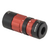 | こちらのコリメータは、ビームをコリメートしたまま、6~18 mmの範囲で焦点距離を変えることができます。そのため、コリメートした状態でビームサイズを変更できます。このデバイスは、用途に適した固定のファイバーコリメータを探す手間を省けるという利点に加え、1つで様々な幅広い用途に対応することができます。FC/PC、FC/APCまたはSMA905コネクタが付いており、反射防止コーティングは3種類からお選びいただけます。 |
| シングルモードファイバーピグテール付きコリメータ | 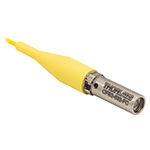 | シングルモードファイバーピグテール付きコリメータは、長さ1メートルのファイバとそれに対して予めアライメントされたARコーティング付き非球面レンズとで構成されており、532 nm、633 nm、780 nm、850 nm、1030 nm、1064 nm、1310 nm、1550 nmの8波長用の製品をご用意しています。コーティング波長域内のどの波長でもコリメートできますが、設計波長からずれると結合損失が増加します。 |
| 偏波保持ファイバーピグテール付きコリメータ | 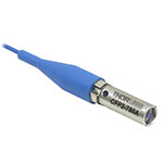 | 偏波保持ファイバーピグテール付きコリメータは、長さ1メートルのファイバとそれに対して予めアライメントされたARコーティング付き非球面レンズとで構成されており、633 nm、780 nm、980 nm、1064 nm、1550 nmの5波長用の製品をご用意しています。波長やコネクタについてはカスタム仕様も対応可能です。筐体の外側にはスロー軸と平行なラインが刻印されています。これは入射光の偏光面をアライメントする際の目安としてお使いいただけます。コーティング波長域内のどの波長でもコリメートできますが、設計波長からずれると結合損失が増加します。 |
| GRINレンズコリメータ |  | GRINレンズファイバーコリメータは、630~1550 nmの範囲内の様々な波長に対してアライメントされた製品をご用意しており、FCまたはAPCコネクタ付きもしくはコネクタ無しのタイプからお選びいただけます。この有効径Ø1.8 mmのGRINレンズコリメータは、ファイバへの後方反射光を抑えるためにARコーティングが施されており、標準のシングルモードファイバまたはグレーデッドインデックス(GI)マルチモードファイバに結合されています。 |
| GRINレンズ |  | この屈折率分布型(GRIN)レンズは630 nm、830 nm、1060 nm、1300 nm、または1560 nmの波長用にARコーティングが施されており、光ファイバから出射した光が自由空間の光学系を通過して再度別のファイバに入射するまでの各用途にご利用いただけます。また半導体レーザの出射光のファイバへの結合、ファイバからの出射光のディテクタへの集光、レーザ光のコリメートなどにも適しています。このGRINレンズは当社の ピグテール付きガラスフェルールやGRINレンズ/フェルール用スリーブと組み合わせてお使いいただくこともできます。 |

| Item # | f (mm) | NAa | Input MFDb | Output Waist Diameter (1/e2) | Max Waist Distancec | Pointing Stability During Collimation | Divergenced | Fiber-to-Lens Distancee | AR Coatingf | Compatible Connector |
|---|---|---|---|---|---|---|---|---|---|---|
| CFC2-A | 2.0 | 0.5 | 3.5 µm | 0.36 mmg | 103.4 mmg | < 15 mrad | 0.100°g | 0.4 - 3.0 mm | 350 - 700 nm | 2.1 mm Wide Key FC/PC |
| CFC2-B | 2.0 | 0.5 | 5.0 µm | 0.43 mmh | 88.6 mmh | < 15 mrad | 0.143°h | 0.4 - 3.0 mm | 600 - 1050 nm | |
| CFC2-C | 2.0 | 0.5 | 10.4 µm | 0.38 mmi | 38.5 mmi | < 15 mrad | 0.298°i | 0.4 - 3.0 mm | 1050 - 1700 nm |

| Item # | f (mm) | NAa | Input MFDb | Output Waist Diameter (1/e2) | Max Waist Distancec | Pointing Stability During Collimation | Divergenced | Fiber-to-Lens Distancee | AR Coatingf | Compatible Connector |
|---|---|---|---|---|---|---|---|---|---|---|
| CFC5-A | 4.6 | 0.53 | 3.5 µm | 0.82 mmg | 541.2 mmg | < 5 mrad | 0.044°g | 2.4 - 4.9 mm | 350 - 700 nm | 2.1 mm Wide Key FC/PC |
| CFC5-B | 4.6 | 0.53 | 5.0 µm | 1.00 mmh | 462.6 mmh | < 5 mrad | 0.062°h | 2.4 - 4.9 mm | 650 - 1050 nm | |
| CFC5-C | 4.6 | 0.53 | 10.4 µm | 0.87 mmi | 197.7 mmi | < 5 mrad | 0.130°i | 2.4 - 4.9 mm | 1050 - 1620 nm |

| Item # | f (mm) | NAa | Input MFDb | Output Waist Diameter (1/e2) | Max Waist Distancec | Pointing Stability During Collimation | Divergenced | Fiber-to-Lens Distancee | AR Coatingf | Compatible Connector |
|---|---|---|---|---|---|---|---|---|---|---|
| CFC8-A | 7.5 | 0.3 | 3.5 µm | 1.33 mmg | 1434.1 mmg | <5 mrad | 0.027°g | 4.2 - 6.8 mm | 350 - 700 nm | 2.1 mm Wide Key FC/PC |
| CFC8-B | 7.5 | 0.3 | 5.0 µm | 1.62 mmh | 1225.0 mmh | <5 mrad | 0.038°h | 4.2 - 6.8 mm | 650 - 1050 nm | |
| CFC8-C | 7.5 | 0.3 | 10.4 µm | 1.42 mmi | 520.7 mmi | <5 mrad | 0.079°i | 4.2 - 6.8 mm | 1050 - 1620 nm |

| Item # | f (mm) | NAa | Input MFDb | Output Waist Diameter (1/e2) | Max Waist Distancec | Pointing Stability During Collimation | Divergenced | Fiber-to-Lens Distancee | AR Coatingf | Compatible Connector |
|---|---|---|---|---|---|---|---|---|---|---|
| CFC11P-A | 11.0 | 0.3 | 3.5 µm | 1.95 mmg | 3079.7 mmg | < 1 mrad | 0.018°g | 8.6 - 10.9 mm | 350 - 700 nm | 2.1 mm Wide Key FC/PC |
| CFC11P-B | 11.0 | 0.3 | 5.0 µm | 2.38 mmh | 2630.1 mmh | < 1 mrad | 0.026°h | 8.6 - 10.9 mm | 650 - 1050 nm | |
| CFC11P-C | 11.0 | 0.3 | 10.4 µm | 2.09 mmi | 1114.9 mmi | < 1 mrad | 0.054°i | 8.6 - 10.9 mm | 1050 - 1620 nm |
 Products Home



 FC/PCコリメータ