 Products Home
1.6 MP CMOS小型サイエンティフィックカメラ

- Monochrome and Color CMOS Cameras
- High Quantum Efficiency and Low <4.0 e- Read Noise
- Versions Available with External Hardware Triggers
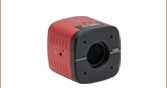
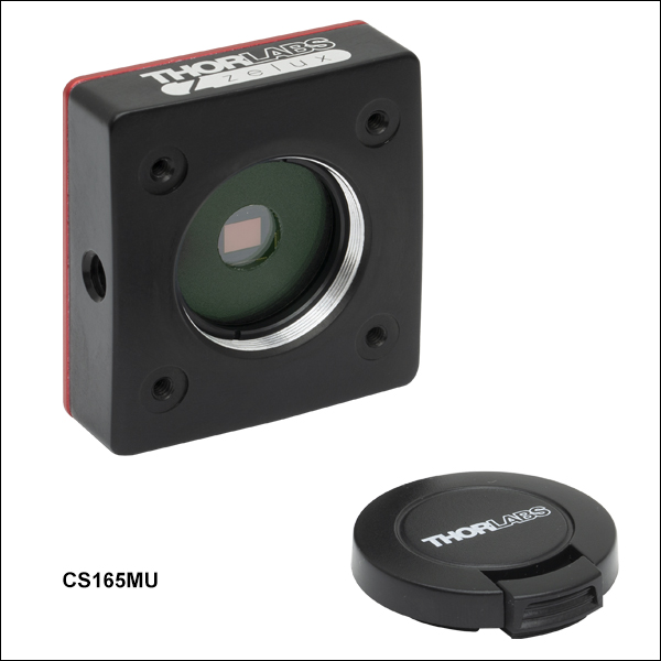
CS165MU1
Monochrome CMOS Camera with External Hardware Trigger
CS165MU
SM1A10Z
MVL4WA
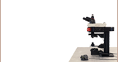
Application Idea
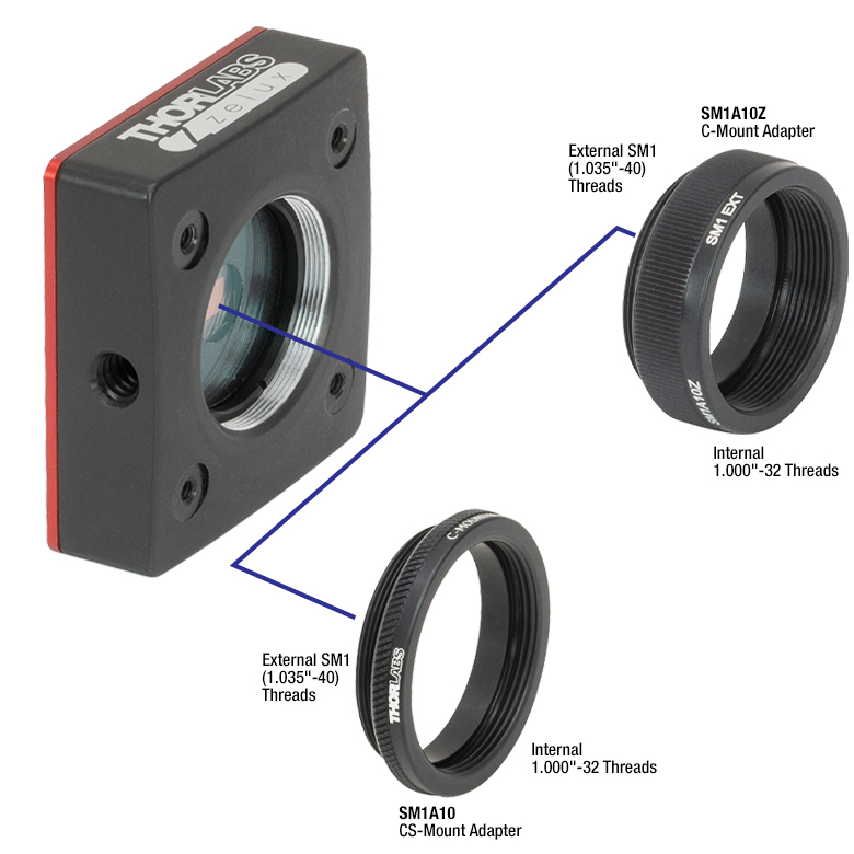
Use the SM1 Threads on the Camera Front with a C-Mount or CS-Mount Adapter
C-Mount and CS-Mount Adapters are Sold Below


Please Wait
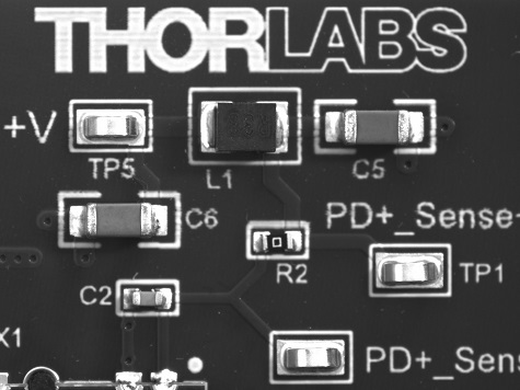
Zelux® CMOSカメラで取得した画像
特長
- モノクロまたはカラーのCMOSセンサ
- 1/2.9インチフォーマット、3.45 µm正方形画素の1440 x 1080ピクセル(1.6 MP)
- 急速な変化もイメージングが可能なグローバルシャッタ
- USB 3.0インターフェイス
- 30 mmケージシステムに取付け可能
- 超小型の筐体:15.0 mm x 43.7 mm x 47.2 mm
- 開口部はSM1ネジ付き
- Cマウント用とCSマウント用のアダプタは別売り(下記参照)
- ポスト取付け用として利用可能なM6タップ穴
ソフトウェア
- Windows®7、10、11用のThorCam™ソフトウェア
- SDKおよびプログラミングインターフェイスは下記をサポート
- C、C++、C#、Python、Visual Basic .NET API
- LabVIEW、MATLAB、µManagerによるサードパーティーソフトウェア
当社の超小型で軽量なZelux®カメラにはCMOSセンサが搭載されており、一般的なイメージング用カメラと同程度の価格でサイエンティフィックカメラのイメージング性能を発揮します。モノクロまたはカラーのCMOSセンサを搭載したカメラをご用意しています。また画像取得のタイミングを外部機器と同期するための外部トリガ用MMCXコネクタについては、付いているタイプと付いていないタイプがございます。このカメラは設置面積が小さいながら、< 4.0 e-の低い読取りノイズと高い感度を有しています。グローバルシャッタにより視野全体を同時にとらえるため、急速に変化する対象をイメージングすることができます。
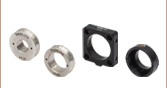
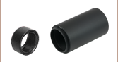
モノクロカメラにはARコーティングされたウィンドウが付いており、カラーカメラには波長650 nm以上の光を遮断する赤外域ブロックフィルタが付いています。固定リングSM1RRで固定されたウィンドウとフィルタは、スパナレンチSPW602またはSPW606(いずれも別売り)で取り外しが可能なため、厚さ1.27 mm以下のØ25 mm~Ø25.4 mm(Ø1インチ)の光学素子に交換が可能です。どちらのタイプのカメラにもUSB 3.0インターフェイスが付いており、当社のソフトウェアThorCamでの制御が可能です。詳細は「ソフトウェア」タブをご覧ください。最新のファームウェアはこちらからダウンロードいただけます。すべてのカメラにスナップオン式レンズキャップSM1EC2Bが付いており、カメラを使用していない時のセンサの保護にご使用いただけます。
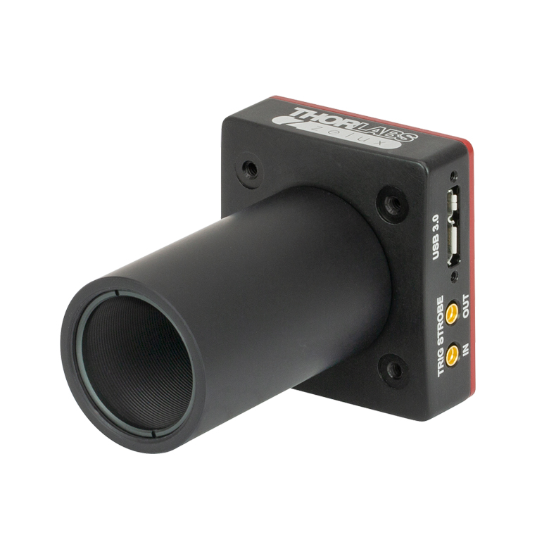
こちらのカメラは小型であるうえに様々な部品と組み合わせて取付けることが可能であり、市販の顕微鏡を用いたイメージングシステムのほか、自作のシステムにも組み込むのに適した製品です。Zeluxカメラ筐体の隣り合う側面にはM6のタップ穴が1つずつあり、Ø25 mmの台座付きポストやピラーポストのほか、多くの標準的な三脚にも取り付けることができます。各カメラの開口部にはØ25 mm~Ø25.4 mm(Ø1インチ)レンズチューブやSM1ネジ付きアダプタを取付けることができるSM1ネジが付いています。下記のCSおよびCマウントアダプタを使用することで、多くの顕微鏡やマシンビジョン用カメラレンズ、さらにCマウントエクステンションチューブにも取り付けられるようになります。対応するマシンビジョン用カメラレンズについては「対応レンズ」タブをご覧ください。当社では、カメラを30 mmケージシステムやSM1レンズチューブに素早く取付けるのに便利な、SM1ネジ付きアリ溝アダプタもご用意しております。また、筐体の前面にある4つの#4-40タップ穴を用いて、当社の30 mmケージシステムに取り付けることもできます。
| Scientific Camera Selection Guide |
|---|
| Zelux® CMOS (Smallest Profile) |
| Kiralux® CMOS |
| Kiralux Polarization-Sensitive CMOS |
| Quantalux® sCMOS (< 1 e- Read Noise) |
Feedback? ご質問や |
| Common Specifications | |
|---|---|
| Number of Active Pixels (Horizontal x Vertical) | 1440 x 1080 |
| Imaging Area (Horizontal x Vertical) | 4.968 mm x 3.726 mm |
| Pixel Size | 3.45 µm x 3.45 µm |
| Optical Format | 1/2.9" (6.2 mm Diagonal) |
| Max Frame Rate | See Table Below |
| ADCa Resolution | 10 Bits |
| Sensor Shutter Type | Global |
| Read Noise | < 4.0 e- RMS |
| Full Well Capacity | ≥11 000 e- |
| Exposure Time | 0.040 ms to 26843 ms in ~0.025 ms Increments |
| Region of Interest (ROI) | 80 x 4 Pixelsb to 1440 x 1080 Pixels, Rectangular |
| Dynamic Range | Up to 69 dB |
| Lens Mount | Internal SM1 (1.035"-40) Threading; SM1A10 CS-Mount Adapter and SM1A10Z C-Mount Adapter Sold Below |
| USB Power Consumption | 1.17 W |
| Ambient Operating Temperature | 10 °C to 40 °C (Non-Condensing) |
| Storage Temperature | 0 °C to 55 °C |
| Item # | CS165MU(/M) | CS165MU1(/M) | CS165CU(/M) | CS165CU1(/M) |
|---|---|---|---|---|
| Sensor Type | Monochrome CMOS | Color CMOS | ||
| Hardware Trigger/Strobe | No | Yesa | No | Yesa |
| Peak Quantum Efficiency | 69% at 575 nm (See Graph Below) | 65% at 535 nm (See Graph Below) | ||
| Removable Optic | AR-Coated Window, Ravg < 0.5% per Surface (400 - 700 nm) | IR Blocking Filterb | ||
| Vertical and Horizontal Digital Binning | 1 x 1 to 16 x 16 | 1 x 1 to 16 x 16c | ||
| Mounting Features | Imperial: Two 1/4"-20 Taps for Post Mounting, 30 mm Cage Compatible Metric: Two M6 Taps for Post Mounting, 30 mm Cage Compatible Taps are on Adjacent Sides of the Housing | |||

Click to Enlarge
Zelux®カメラの筐体の概略図 MMCXコネクタは、外部ハードウェアによるトリガ機能付きのタイプにのみ付いています。ミリ規格製品の寸法は括弧内に記載されています。
| Example Frame Rates at 1 ms Exposure Timea | |
|---|---|
| Region of Interest | Frame Rate |
| Full Sensor (1440 x 1080) | 34.8 fps |
| Half Sensor (720 x 540) | 67.0 fps |
| 1/10 Sensor (144 x 108) | 260.0 fps |
| Minimum ROI (80 x 4) | > 800 fps |
Click to Enlarge
Click for Raw Data
各グラフはカラーカメラセンサの赤色、緑色、青色に対応するピクセルの相対感度を示しています。このデータでは取り付けられた赤外域ブロックフィルタによる吸収は考慮していません。650 nmより長波長側の青い網掛け部分は取り外し可能なフィルタによってブロックされる波長域です。
Click to Enlarge
Click for Raw Data
曲線は赤外域ブロックフィルタの典型的な透過率を示しています。このフィルタは取り外すことができ、Ø25 mm~Ø25.4 mm(Ø1インチ)光学素子(厚さ1.27 mm以下)に置き換えることができます。
カメラ側面パネル内のコネクタ位置

ZeluxカメラCS165MU/MとCS165CU/Mの側面パネルに配置された
USB3.0コネクターポート

ZeluxカメラCS165MU1/MとCS165CU1/Mの側面パネルに配置された
USB3.0コネクターポートと2つのMMCXコネクターポート

Click to Enlarge
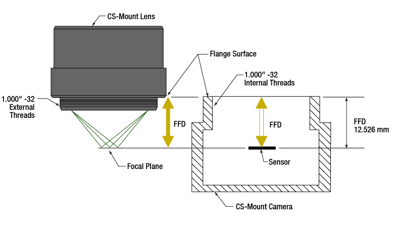
CマウントとCSマウントのフランジ-焦点間距離
Click to Enlarge
スペーサの長さ
Click for Details
当社のZeluxカメラにCマウントまたはCSマウントのレンズを取り付けるためのアダプタ
対応するCマウントおよびCSマウントレンズ
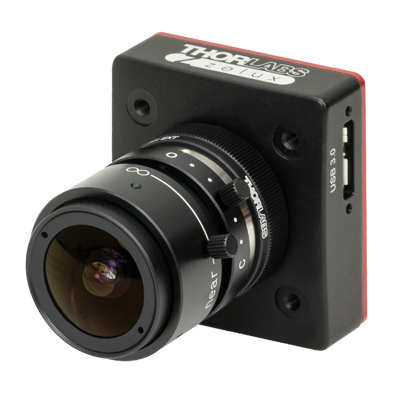
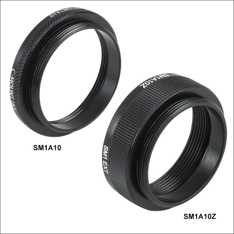
当社のZelux®カメラには、アダプタSM1A10Zを使用するとCマウントレンズを、アダプタSM1A10を使用するとCSマウントレンズを取付けることができます。 右の画像でご覧いただけるように、これらのアダプタはZeluxカメラのSM1ネジ付き開口部に直接取付けられます。アダプタSM1A10ZとSM1A10については下記をご参照ください。
CおよびCSマウントのネジ規格はどちらも1.00"-32ですが、フランジ-焦点間距離(FFD)はCマウントの方がCSマウントよりも5 mm長くなっています(右端の図参照)。アダプタのスペーサの長さは、右側中央の図のように定義しています。
カメラレンズの選択について
CCDやCMOSセンサを用いた現代のカメラではカメラセンサーフォーマットが明示され、レンズも特定のカメラフォーマットに対して適切にイメージングできるように設計されています。このフォーマットの呼称(例:1/2インチ、2/3インチ、4/3インチ)は、ブラウン管でビデオを表示していた頃からの名残で、ある画像サイズを得るために必要なブラウン管の外径のことです。Zeluxカメラの光学フォーマットは1/2.9インチです(対角長6.2 mm)。 イメージングシステムにおいてカメラとレンズが同じフォーマットで設計されていることが理想的ですが、異なったフォーマットのカメラとレンズを組み合わせることも可能です。フォーマットが異なる場合は、得られる画像にビネットまたはクロップが現れます。ビネットは、レンズフォーマットがカメラフォーマットより小さいときに生じ、クロップはレンズフォーマットがカメラフォーマットより大きい場合に生じます。詳細については「カメラレンズチュートリアル」をご覧ください。
当社ではアダプタSM1A10Zを使用してZelux CMOSカメラに取付けられる様々なCマウントカメラレンズをご用意しております。カメラレンズを選択する際は、下記のCompatible C-Mount Camera Lensesの表で仕様をご確認ください。
| Zelux Camera Parameters | |||
|---|---|---|---|
| Number of Active Pixels (Horizontal x Vertical) | Imaging Area (Horizontal x Vertical) | Pixel Size | Optical Format |
| 1440 x 1080 | 4.968 mm x 3.726 mm | 3.45 µm x 3.45 µm | 1/2.9" (6.2 mm Diagonal) |
| Compatible C-Mount Camera Lensesa | |||||||||
|---|---|---|---|---|---|---|---|---|---|
| Item # | Lens Parameters | Estimated Performance at the Specified Object Working Distanceb | |||||||
| Focal Length | Angular Field of Viewc | Minimum Working Distance | Object Working Distance | Optical Magnification | Field of View | Smallest Resolvable Size | |||
| Diagonal | H | V | |||||||
| MVL4WA | 3.5 mm | 81.2° | 200 mm | 200 mm | 0.02 | 343 mm | 274 mm | 206 mm | 0.39 mm |
| MVL5WA | 4.5 mm | 67.4° | 200 mm | 200 mm | 0.02 | 267 mm | 213 mm | 160 mm | 0.31 mm |
| MVL6WA | 6 mm | 51.1° | 200 mm | 200 mm | 0.03 | 191 mm | 153 mm | 115 mm | 0.23 mm |
| MVL8M23 | 8 mm | 66.7° | 100 mm | 120 mm | 0.07 | 76 mm | 61 mm | 46 mm | 0.10 mm |
| MVL12WA | 12 mm | 28.1° | 300 mm | 300 mm | 0.04 | 150 mm | 120 mm | 90 mm | 0.17 mm |
| MVL12M23 | 12 mm | 26.6° | 150 mm | 150 mm | 0.08 | 71 mm | 57 mm | 43 mm | 0.09 mm |
| MVL16M23 | 16 mm | 20.4° | 200 mm | 200 mm | 0.08 | 72 mm | 58 mm | 43 mm | 0.09 mm |
| MVL25M23 | 25 mm | 13.2° | 200 mm | 200 mm | 0.13 | 46 mm | 37 mm | 28 mm | 0.06 mm |
| MVL35M23 | 35 mm | 9.8° | 200 mm | 200 mm | 0.18 | 34 mm | 27 mm | 21 mm | 0.04 mm |
| MVL50M23 | 50 mm | 12.1° | 200 mm | 200 mm | 0.25 | 23 mm | 18 mm | 14 mm | 0.03 mm |
| MVL75M23 | 75 mm | 4.6° | 1200 mm | 1200 mm | 0.06 | 96 mm | 77 mm | 58 mm | 0.11 mm |
| MVL100M23 | 100 mm | 3.4° | 2000 mm | 2000 mm | 0.05 | 119 mm | 95 mm | 71 mm | 0.14 mm |
ThorCam™
ThorCamは強力な画像取得ソフトウェアパッケージで、当社のカメラを32ビット版または64ビット版のWindows® 7、10または11で使用できるように設計されています。直観的で使いやすいグラフィカルインターフェイスを用いて、カメラ制御やイメージの取得・再生が可能です。シングルイメージキャプチャとイメージシーケンスをサポートしています。ソフトウェアの基本的な機能については、下記のスクリーンショットをご覧ください。
アプリケーションプログラミングインターフェイス(API)とソフトウェア開発キット(SDK)が付属しているため、OEMや開発業者によるカスタムアプリケーションの開発も可能です。SDKは、C、C++、C#、Python、Visual Basic .NETなど幅広いプログラミング言語に対応しています。また、LabVIEW、MATLABなどのサードパーティソフトウェアパッケージもサポートしています。
お貸し出し用のZelux®カメラをご使用中のお客様で、ソフトウェアの性能やダウンロードについての情報をお知りになりたい方は当社までご連絡ください。
| Recommended System Requirementsa | |
|---|---|
| Operating System | Windows® 7, 10, or 11 (64 Bit) |
| Processor (CPU)b | ≥3.0 GHz Intel Core (i5 or Higher) |
| Memory (RAM) | ≥8 GB |
| Hard Drivec | ≥500 GB (SATA) Solid State Drive (SSD) |
| Graphics Cardd | Dedicated Adapter with ≥256 MB RAM |
| Motherboard | Integrated Intel USB 3.0 Controller or One Unused PCIe x1 Slot (for Item # USB3-PCIE) |
| Connectivity | USB or Internet Connectivity for Driver Installation |
色付きの枠で囲まれた部分をクリックするとThorCamの機能がご覧いただけます。
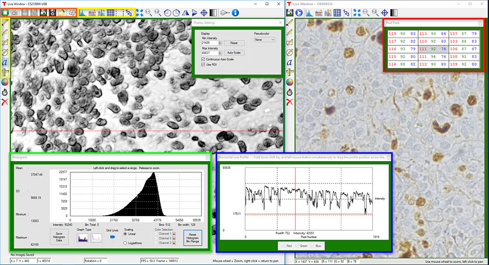
カメラ制御および画像取得
カメラ制御および画像取得の機能は、ウィンドウの上にあるアイコン(上の画像中のオレンジの枠内)から実行できます。カメラパラメータの設定は、ツールアイコンをクリックすると表示されるポップアップウィンドウで行えます。スナップショットボタンを押すと、現在のカメラ設定を使用した1枚の画像が取得できます。
キャプチャスタート/ストップボタンを押すと、トリガーモードなども含むカメラ設定に従って画像取得を開始します。
時系列および像系列のレビュー
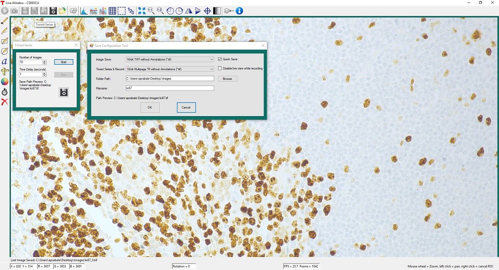
図1のような時系列制御により、タイムラプス画像の記録ができます。画像の総数と画像間の遅延時間を設定してください。出力は、高精度の無修正画像データとして保存するために、マルチページTIFFファイルとして保存されます。ThorCam内で、画像のシーケンス再生やフレームごとのコマ送り再生が可能です。
測定および注釈機能
上の画像の黄色い枠内にあるように、ThorCamには注釈および測定機能が多数内蔵されています。これらは取得後の画像を分析する際に役立ちます。直線、長方形、円およびフリーハンドによる図形を画像上に描くことができます。注釈マークを付けた位置には文字を入力できます。 また、測定モードでは対象とする2点間の距離を計測できます。
上の画像内の赤、緑、青の枠で囲まれた部分に、ライブ画像または取得済み画像に関する情報を表示することができます。
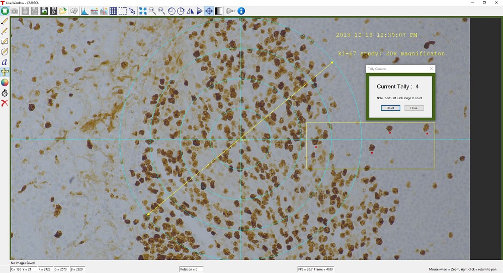
ThorCamには計数機能も内蔵されており、画像内の興味ある対象に印をつけてその数を計数することができます(図2参照)。 画像の中心に固定されている十字のターゲットが基準点となります。
サードパーティアプリケーションおよびサポート
ThorCamは、LabVIEW、MATLAB、.NET.などのサードパーティソフトウェアパッケージもサポートしています。LabVIEWとMATLABは32ビット版と64ビット版の両方をサポートしています。 当社カメラに付属する解説付きのフル機能APIを使えば、フルカスタマイズのアプリケーションを効率的に開発できます。
Click to Enlarge
図1:1秒間隔で撮影された10枚の時系列画像が、マルチページTIFFファイルとして保存されます。
Click to Enlarge
図2:ThorCamソフトウェアで表示された解析結果と注釈機能のスクリーンショット。計数機能によって画像内の4地点がマークされています。画像の中心に固定されている青い十字のターゲットが基準点となります。
性能に関する注意点
イメージシーケンスをディスクに保存するときに、システム性能が十分でないと「フレーム落ち」が発生する可能性がありますのでご注意ください。ホストシステムがカメラの出力データストリームを処理する能力は、ホストシステムの様々な特性に依存します。USBハブを使用すると性能に影響を与える可能性があります。 PCとは専用ケーブルで接続することをお勧めいたします。USB 2.0による接続はサポートされておりません。
まず、カメラのフレームレートと、ホストPCが画像を表示する能力およびフレーム落ちせずにディスクにストリーミングする能力とを区別することが重要です。カメラのフレームレートは露光および読み出しパラメータ(例えば、クロックやROI)に依存します。ユーザによって設定された画像取得パラメータに基づいて、カメラのタイミング機能はデジタルカウンタのように動作し、1秒間にある特定の数のフレームを生成します。画像を表示するときは、このデータがPCのグラフィックシステムによって処理され、画像や動画を保存するときにはディスクに転送されます。この時、ハードドライブの速度が十分でないとフレーム落ちが発生します。
この問題に対する解決策の一つとして、ソリッドステートドライブ(SSD)のご使用をお勧めいたします。PCのそれ以外の仕様が十分であれば、多くの場合はこれによって解決します。SSDへの書き込み速度は、データのスループットを処理するのに十分なものでなければなりません。
大きなフォーマットの画像を早いフレームレートで処理する場合には、より速いスピードが必要な場合があります。その場合は、複数のSSDを用いてRAID0を構成するか、あるいはRAMドライブを使うといった方法が考えられます。後者の方法では保存スペースがPC上のRAMで制限されてしまいますが、実現可能な方法としては最も高速なものです。 ImDiskは、無料のRAMディスク作製用ソフトウェアパッケージの一例です。RAMドライブは揮発性メモリであることにご注意ください。従って、データの損失を防ぐために、PCを再起動またはシャットダウンする前に、必ずデータをRAMドライブから不揮発性のハードドライブに移動させることが重要です。
カメラのトリガ操作
当社のZelux®サイエンティフィックカメラには、MMCXコネクタの有るタイプと無いタイプがあります。このコネクタは、他のデバイスと画像取得動作を同期させるための外部トリガ信号の入力に使用します。MMCXコネクタ付きのZeluxカメラには3種類の外部トリガーモード(ストリーミングオーバーラップ、非同期トリガ、バルブ撮影)があり、その動作には外部で生成したトリガーパルスが必要です。トリガーモードは利得やオフセットと同様に、読み出し設定(例:ビニング)とは独立に動作します。下の図1~3はこれらのトリガーモードのタイミング図です。アクティブロー外部TTLトリガを想定しています。
Click to Enlarge
図1:ストリーミングオーバーラップ露光 外部トリガ信号がローになると露光が始まり、ソフトウェアで選択された時間の露光が継続され、次に読み出しが行われます。このシーケンスは設定された時間間隔で繰り返されます。後続の外部トリガは、カメラ動作が停止するまで無視されます。
Click to Enlarge
図2:非同期トリガ画像取得モード 外部トリガ信号がローになるとプリセットされた時間の露光がはじまり、次に読み出しが行われます。読み出し中の外部トリガは無視されます。1回の読み出しが終わると、カメラの次の露光は外部トリガ信号が次にローになったときに始まります。
Click to Enlarge
図3:バルブ露光モード 外部トリガ信号がローになると露光が始まり、ハイになると露光が終わります。カメラの読み出し中のトリガ信号は無視されます。
カメラに特有なタイミングに関する考慮事項
当社のZelux CMOSセンサーカメラの一般的な動作特性とシステム固有の伝搬遅延により、上記のタイミングに関して下記の事項を考慮する必要があります。
- 外部トリガから露光開始およびストローブ信号出力までの遅延時間は、すべてのトリガモード(標準およびBulb)において12 µs~15.5 µs(典型値)です。
- Bulbモードによる露光の場合、露光開始での12 µs~15.5 µsの遅延時間のほかに、外部トリガの立ち下がりエッジ後に一定の露光時間が生じます。この時間はこのセンサの動作に固有のものです。CS165シリーズ製品におけるこの露光時間は14.26 µsです。
Strobe_out信号にはこの付加された一定の露光時間が含まれているため、Strobe_out信号は実際の露光時間により近い時間を表しています。 そのため、Strobe_Out信号を使用して露光時間を測定し、その結果に従ってバルブモードのトリガーパルスを調整する事をお勧めいたします。
カメラのノイズと温度
概要
カメラの購入時に重要となるのは、冷却センサが必要かどうかの判断です。一般的な多くの用途では信号レベルが高いために、冷却は必要ではありません。 しかし低光量の状況下では長い露出時間が必要なため、ほとんどの場合冷却タイプがメリットをもたらします。 下に掲載しているチュートリアルでは以下の経験則を証明しています。1秒未満の露出時間にはほとんどの場合、標準(非冷却)のカメラが適当で、1秒以上の露出時間では冷却タイプが有効です。5秒以上の 露出時間には冷却タイプをお勧めします。また、10秒以上の露出時間では通常冷却タイプが必要となります。 どちらの用途か迷う場合には、下記チュートリアルに記載されている計算式を用いて信号レベルならびにノイズ値をお求めになることをお勧めします。 下記では当社の1.4メガピクセルカメラの仕様を用いた計算例を示しています。ご不明な場合は当社までご相談ください。
ノイズの原因
カメラ画像のノイズの原因は、照明が安定して均一であると仮定すると、測定信号の空間的・時間的バラツキの積み重ねであると言えます。 ノイズには複数の要因があります:
- ダークショットノイズ (σD): 暗電流とは、カメラに全く光子が入射しない状況でも流れている電流です。 熱によって引き起こされる現象で、シリコン製のチップから自然発生的に起こる電子(価電子は熱によって伝導バンドに励起されます)によるものです。 露光中に取得される暗電子の量のバラツキがダークショットノイズです。 表1でみられるように、この数値は信号レベルには依存しませんが、センサ温度には依存します。
- 読取りノイズ(σR): これは電子信号を生成する際に発生するノイズです。センサの設計が引き起こすノイズですが、カメラの電子部品の設計の影響も受けます。このノイズは、信号レベルやセンサ温度には影響を受けず、CCDピクセルクロックレートが高速になると大きくなります。
- フォトンショットノイズ (σS): フォトンショットノイズは、光子がピクセルに達する際に起こる統計的ノイズです。 フォトンの測定はポアソン統計に従うため、フォトンショットノイズは、測定される信号レベルに依存します。 なお、センサ温度には依存しません。
- 固定パターンノイズ (σF): このノイズは、ピクセルの空間的な不均一性が原因で、信号レベルやセンサ温度には無関係です。 なお、固定パターンノイズは、下記の説明においては考慮に入れないこととします。このノイズはここで販売されるCCDカメラにはあまり関係のないノイズですが、サイエンス用よりも低グレードの他のセンサを検討する上では必要となる場合があります。
有効ノイズの総量
1個のピクセルあたりの有効ノイズの総量とは、上記のノイズの求積法による和です。
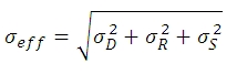
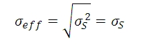
ここでは、σDがダークショットノイズ、 σRが読取りノイズ (CCD ICX285ALを使用しているサイエンス用レベルのカメラでの典型値は10 e-未満ですが、このチュートリアルでは、10 e-であると仮定します)、そしてσS がフォトンショットノイズです。 σS>>≫σD であり、σS>>σRである時、下記の数式で近似的にσeffが求められます:
繰り返しますが、ここでは固定パターンノイズは考慮に入れません。そしてこのことはサイエンス用のCCDを考える上では妥当かもしれませんが、サイエンス用よりもグレードの低いセンサでは、考慮に入れなければならない場合もあると考えます。
| Temperature | Dark Current (ID) |
|---|---|
| -20 °C | 0.1 e-/(s•pixel) |
| 0 °C | 1 e-/(s•pixel) |
| 25 °C | 5 e-/(s•pixel) |
Click to Enlarge
図1: 3つのセンサ温度において、露出時間の変化にともなうダークショットノイズと読取りノイズの変化を示したグラフです。 このグラフではxy軸はともに対数目盛です。5 sのところで縦に点線が引かれていますが、これは文章内の数式例での数値です。
ダークショットノイズとセンサ温度
上述のように、暗電流は熱によって生じるため、センサを冷却することで低減できます。表1は、CCDセンサを用いたカメラ(サンプル)の暗電流の典型値を示しています。暗電流は自然発生した電子によって起こるので、単純に電子の数を「数える」ことで測定されます。 電子のカウントはポワソン統計に従うため、暗電流 IDが引き起こすノイズは、露出中に蓄積する暗電子の数の平方根に比例します。 既知の露出において、ダークショットノイズ σDは、表1に記載のある IDの値 (既知の温度に対応した数値) と露出時間t(秒)の積の平方根となります。
暗電流は、温度の低下に伴って減少するので、これに関連したノイズはカメラの冷却で低減できます。 例えば露出時間が5秒であるとき、表で示される3つのセンサ温度でのダークショットノイズレベルは下記の数式で得られます。
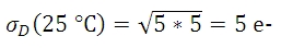
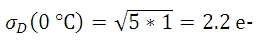
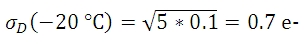
図1はプロット図で、表1の3つの温度における露出時間とダークショットノイズの関係を表し、露出時間が増えるにつれてダークショットノイズが増大することがわかります。 図1には、読取りノイズの上限も示されています。
フォトンショットノイズがダークショットノイズと比較して十分に大きければ、ノイズに対する影響という意味では冷却がもたらすメリットは小さく、そのような条件でもカメラは十分に機能します。
フォトンショットノイズ
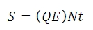
量子効率がQEのセンサの各ピクセルに入射する光量子束密度(フォトン/秒)がNであるとして、露出時間がt秒のときに生成される「信号」の電子の数がSとすると
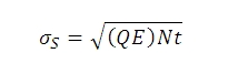
Sから、フォトンショットノイズ σSは下記の数式で求められます:
計算例(当社の1.4メガピクセルカメラを使用)
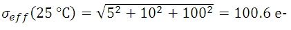
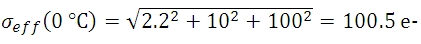
光量子束密度と量子効率が十分に高い値で、露出時間が5秒の時にピクセルに蓄積される信号 S の数が10,000 e-であれば、予測されるショットノイズの値 σSは、10,000の平方根または100 e-となります。 読取りノイズは10 e-です (露出時間に依存しません)。 露出時間が5秒で、センサ温度が25、 0、 -25 °Cであるとき、ダークショットノイズは数式(4)によって得られます。 有効ノイズは下記のとおりです:

信号対雑音比(SNR)は、画像品質を示す便利な性能指数で、下記の通り見積もられます:
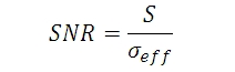
数式7から3つのセンサ温度におけるSNRの値は下記の数式であらわすことができます:
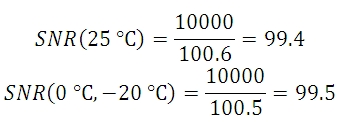
この例でわかるように、室温では非冷却タイプカメラの代わりに冷却型タイプを使うメリットはほとんどなく、この例ではフォトンショットノイズが主なノイズの原因となっています。 このような条件では、当社の標準タイプのパッケージのカメラは十分な性能を発揮することが予測されます。
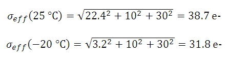
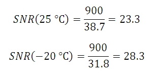
しかし、光量が低いために1個のピクセルあたり900 e-の数値を達成する上で100秒の露出時間が必要な時には、ショットノイズは30 e-となります。 予測されるダークショットノイズは25 °Cで22.4 e- となり、一方で-20 °C でのダークショットノイズは3.2 e-となります。 有効な総ノイズ量は下記の数式で示すことができます。
数式8からSNR値が下記であることが導出できます。
| Exposure | Camera Recommendation |
|---|---|
| < 1 s | Standard Non-Cooled Camera Generally Sufficient |
| 1 s to 5 s | Cooled Camera Could Be Helpful |
| 5 s to 10 s | Cooled Camera Recommended |
| > 10 s | Cooled Camera Usually Required |
この例では25 °Cのセンサにおけるダークショットノイズの総ノイズ量に対する影響は、-25 °Cのセンサよりも大きくなっています。 用途によって許容されるノイズ量は変化しますが、場合によっては冷却型カメラの方が有効な場合があります。
図2 は、3つの異なるセンサ温度でのダークショットノイズをはじめとした様々なノイズの要素の変化をプロットで表していますが、3種類の光量子束密度において、露出時間を変化させて比較しています。 このプロットを見ると、ダークショットノイズは総ノイズ量に大きく影響していませんが、信号レベルが低いとき(そしてその結果として露出時間が長い場合)は例外です。 図においては、計算で使われれる光量子束密度が示されていますが、各用途において冷却モデルのカメラを使用するか否かの判断では、正確な光量子束密度の値は必要ではありません。 図2をご参照いただければ、露出時間に対する数値的な目安がわかるようになっており、露出時間の予測がつけば冷却モデルのカメラが必要であるかどうかがわかります。その概要は表2にまとめてあります。 ノイズの主な原因が読取りノイズだと判明した場合、読取りノイズを低くするために、より低い20 MHzのCCDピクセルクロック速度でカメラを動作することを推奨します。
図2: 3つの光量子束密度で、露出時間を変化させた場合の総ノイズ量(すべてのノイズ源からの合計)の推移を図示しています。(a) 低い光量子束密度(b)中程度の光量子束密度 (c) 高い光量子束密度 (c)では、露出時間が約20秒を超えると、信号電子とフォトンショットノイズが飽和状態になっています。これは、この露出時間に対応する入射光子レベルに対してピクセルが飽和状態に達するためです。 この計算では、量子効率は60% としています。 なお、これらのプロット図ではxy軸で対数目盛を使っていることにご注意ください。
その他の考慮すべき点
ノイズの総量に対してダークショットノイズが大きく影響を与えない場合でも露出時間が長いときには、熱電対冷却を検討する必要があります。これはホットピクセルの影響を低減する一助となるからです。 ホットピクセルは、露出時間が長いときに、「星」のようなパターンの原因となります。 図3 では、その「星」のようなパターンが示されていますが、ここでは露出時間が10秒のときにTEC冷却素子を用いた場合と用いない場合を比較しています。

(a)

(b)
図3: この画像ではホットピクセルが引き起こした「星」のようなパターンを(a)標準タイプの非冷却モデルのカメラおよび (b) -20 °Cに冷却したカメラで比較しています。いずれも露出時間は10秒で、利得は32 dB です(ホットピクセルがはっきりと見えるように利得を調整しました)。 なお、ここで示されている画像は、フル解像度の16 bit画像から切り取ったものです。 フルサイズの16 bit画像を見るにはこちらからダウンロードしてください。 この画像は無料でダウンロードが可能なImageJなどでご覧いただくことができます。

Insights:当社のサイエンティフィックカメラへのレンズの取付けについて
ここでは、当社のサイエンティフィックカメラを中心に、カメラのマウントとレンズの互換性についてご覧いただけます。
- CマウントとCSマウントのカメラとレンズに互換性はあるか
- 当社のサイエンティフィックカメラにアダプタは必要か
- フランジバックがカメラのフランジとセンサ間の距離よりも短くなり得る理由は
実験および機器についての「Insights-ヒント集」はこちらからご覧いただけます。
CマウントとCSマウントのカメラとレンズに互換性はあるか
Click to Enlarge
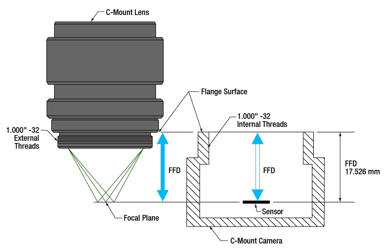
図1: Cマウントのレンズとカメラのフランジバックは同じで、17.526 mmです。そのためレンズを通る光は必ずカメラのセンサ上に焦点を結びます。どちらのコンポーネントにも1.000"-32ネジが付いており、これらは「C-マウントネジ」とも呼ばれます。
Click to Enlarge
図2:CSマウントのレンズとカメラのフランジバックは同じで、12.526 mmです。そのためレンズを通る光は必ずカメラのセンサ上に焦点を結びます。1.000"-32ネジはCマウントのコンポーネントに付いているネジと同じで、これらは「Cマウントネジ」とも呼ばれます。
CマウントとCSマウントのカメラシステムにはどちらも1.000"-32ネジが付いていますが、この2つのマウントのフランジバック(フランジ焦点距離/FFD、フランジ焦点深度、フランジ-フィルム間距離などとも呼ばれる)は異なります。Cマウントのフランジバックは17.526 mm(図1)、CSマウントのフランジバックは12.526 mm(図2)です。
フランジバックが異なるため、CマウントとCSマウントのコンポーネントには互換性がありません。しかしアダプタを用いることによってCマウントレンズをCSマウントカメラに使用することは可能です。
CマウントとCSマウントの組み合わせ
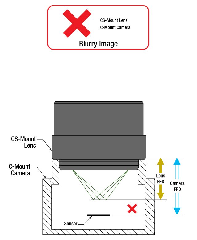
CマウントとCSマウントのネジ規格は同じですが、マウントの種類が異なるレンズとカメラを直接取り付けることはできません。直接取り付けると、フランジバックが異なるためレンズの焦点面がカメラのセンサ面と一致せず、象がぼやけます。
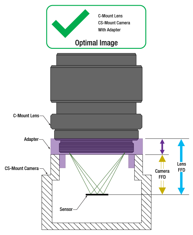
アダプタを使用することで、CマウントレンズをCSマウントカメラに使用することはできます(図3、4)。アダプタによりレンズとカメラのセンサの間隔が5.0 mmだけ長くなり、レンズの焦点面を確実にカメラのセンサ面に一致させることができます。
一方、フランジバックの短いCSマウントレンズは、Cマウントカメラには使用できません(図5)。レンズとカメラの筐体が干渉してカメラのセンサに焦点が合う位置までレンズを近づけることができず、またレンズを近づけられるようなアダプタはありません。
レンズとカメラのパラメータを確認し、互換性のあるコンポーネントなのかどうか、アダプタが必要かどうか、また互換性を持たせる手段はないかを判断することが重要です。
1.000"-32ネジ
インチ規格のネジは、その径とTPI(1インチあたりのネジ山数)によって正確に表現されています。これらの両方のマウントのネジ径は1.000インチ、TPIは32です。Cマウント製品の普及により、1.000"-32ネジは「Cマウントネジ」と呼ばれることがあります。しかし、CSマウントデバイスにも同じネジが用いられているため、この用語は混乱を招く場合があります。
フランジバックについて
フランジバックの値はレンズとカメラの両方について与えられます(図1、2)。レンズの場合、フランジバックはレンズのフランジ面から焦点面までの距離です。フランジ面はレンズ後方のフラットな面で、1.000"-32外ネジとその起点で交差しています。カメラの場合、フランジバックはカメラの前面からセンサ面までの距離です。 レンズがアダプタ無しでカメラに取り付けられているとき、カメラ前方のフランジ面とレンズ後方の面は接触しています。
Click to Enlarge
図5:CSマウントレンズをCマウントカメラに直接取り付けると、光はカメラのセンサの手前で焦点を結びます。この場合はフランジバックを青色の矢印の距離だけ短くする必要がありますが、これはアダプタなどでは対処できません。
Click to Enlarge
図4: 紫色の矢印が示す距離に相当する適切な厚さのアダプタを使用すると、Cマウントレンズの位置はCSマウントカメラのセンサから最適な位置に配置されます。これによりフランジバックが異なっても、光はカメラのセンサ上に焦点を結ぶことができます。

Click to Enlarge
図3:マウントレンズとCSマウントカメラは、レンズのフランジバック(青色の矢印)とカメラのフランジバック(黄色の矢印)が異なるため、直接取り付けることはできません。光はカメラのセンサ上に焦点を結ばす、像がぼやけます。
最終更新日:2020年7月21日
当社のサイエンティフィックカメラにアダプタは必要か
Click to Enlarge
図6:アダプタを使用することで、フランジバックが17.526 mmよりも短いカメラに対して、Cマウントレンズを適切な位置に配置することができます。この図は、ZeluxカメラとアダプタSM1A10Zをもとに描かれています。
Click to Enlarge
図7: アダプタを使用することで、フランジバックが12.526 mmよりも短いカメラに対して、CSマウントレンズを適切な位置に配置することができます。この図は、ZeluxカメラとアダプタSM1A10をもとに描かれています。
当社のサイエンティフィックカメラKiralux™およびQuantalux®は、すべてCマウントレンズに対応するように予め設定されています。これらのパッシブ冷却方式のカメラからCマウントアダプタを取り外すと、フランジ内のSM1内ネジがご利用いただけます。サイエンティフィックカメラZeluxの取付けフランジにもSM1内ネジが付いています。またCマウントアダプタやCSマウントアダプタもご利用いただけます。
カメラ筐体にはSM1ネジが付いており、これによって当社のコンポーネントで構成されたレンズアセンブリを容易に使用することができます。アダプタを使用すれば、カメラのCマウント構成を変えることも可能です。用途に特化したレンズアセンブリを設計する場合や、そのカメラ用に設計されたものではないアダプタを使用しようとする場合には、カメラとレンズのフランジバック(FFD)が一致し、またカメラセンサのサイズが視野に適していることを確認することが重要です。
カメラとそのアダプタ
ZeluxカメラをCマウントやCSマウント規格に適合する構成に変換するための固定式アダプタをご用意しております(図6、7)。これらのアダプタは、パッシブ冷却方式のKiraluxおよびQuantaluxカメラに付属する調整機能付きCマウントアダプタと同様に、それぞれのカメラ専用に設計されています。
SM1ネジを1.000"-32ネジに変換するアダプタであれば、どの様なものでもカメラにCマウントやCSマウントのレンズを取り付けることが可能ですが、すべてのネジアダプタがレンズの焦点面を特定のカメラのセンサ面に一致させることができるわけではありません。場合によっては、それらの面を一致させられるアダプタが無いことがあります。例えば、こちらのサイエンティフィックカメラでは、ZeluxカメラだけがCSマウントレンズ用の構成にすることができます。
レンズの焦点面の位置は、空気中で測定されるレンズのフランジバックと、レンズとカメラセンサ間に置かれた屈折率を有する全ての光学素子との組み合わせで決定されます。レンズによって集光される光が屈折率を有する光学素子を透過すると、空気中を伝搬する場合とは異なり、焦点面はより遠い位置に移動します(この距離は算出可能)。 このアダプタは、カメラのフランジバックが短いときに、そのフランジバックの長さと、レンズとセンサ間のウィンドウやフィルタによって生じる焦点移動の両方を補正するのに十分な距離を付加するものでなければなりません。
調整機能付きCマウントアダプタ
パッシブ冷却方式のカメラKiraluxおよびQuantaluxは、SM1内ネジ付きカメラ、固定リングで固定されたウィンドウまたはフィルタ(センサの覆い)、および調整機能付きCマウントアダプタから構成されています。
調整機能付きCマウントアダプタの利点は、ウィンドウまたはフィルタと固定リングが取り付けられている時に、レンズとカメラ間の距離を1.8 mmの範囲で調整できることです。調整可能なことで、カメラのセンサ面とレンズの焦点面のミスアライメントによる様々な影響を補正することができます。それらの影響には、温度変化による材料の膨張や収縮、累積公差による位置誤差、異なる厚さや屈折率のウィンドウまたはフィルタに交換したことに伴う焦点シフトなどが含まれます。
無限遠にある物体の鮮明な像を得るためには、カメラのアダプタの調整が必要な場合があります。物体が無限遠にある場合には入射光は平行光であり、レンズのフランジバックは焦点の位置で決定されます。レンズやカメラの実際のフランジバックが意図したフランジバックと一致していない場合があり、無限遠の物体が焦点を結ぶ面がセンサ面からシフトし、そのため像がぼやけてしまうことがあります。
レンズの焦点調整をしても無限遠の物体の鮮明な像が得られない場合には、カメラのアダプタで調整してみてください。アダプタで調整することで公差や環境によるシフトが補正され、像の焦点を合わせることができます。
最終更新日:2020年8月2日
フランジバックがカメラのフランジとセンサ間の距離よりも短くなり得る理由は
Click to Enlarge
図9:屈折率の違い(θm vs. θo )により光線が屈折するため、光線の光軸に対する角度は空気中よりも媒質内で浅くなります(nm vs. no )。媒質内でdの距離を伝搬したとき、光線は hm しか光軸に近くなりません。そのため、光線はfの位置よりもΔfだけ遠い位置で光軸と交差します。
Click to Enlarge
図8:空気中を通る光線は、f.位置で光軸と交差します。光線は距離dを伝搬すると、hoだけ光軸に近くなります。空気の屈折率はno です。
| Example of Calculating Focal Shift | |||
|---|---|---|---|
| Known Information | |||
| C-Mount FFD | f | 17.526 mm | |
| Total Glass Thickness | d | ~1.6 mm | |
| Refractive Index of Air | no | 1 | |
| Refractive Index of Glass | nm | 1.5 | |
| Lens f-Number | f / N | f / 1.4 | |
| Parameter to Calculate | Exact Equations | Paraxial Approximation | |
| θo | 20° | ||
| ho | 0.57 mm | --- | |
| θm | 13° | --- | |
| hm | 0.37 mm | --- | |
| Δf | 0.57 mm | 0.53 mm | |
| f + Δf | 18.1 mm | 18.1 mm | |
| Equations for Calculating the Focal Shift (Δf ) | ||
|---|---|---|
| Angle of Ray in Air, from Lens f-Number ( f / N ) |  | |
| Change in Distance to Axis, Travelling through Air (Figure 8) |  | |
| Angle of Ray to Axis, in the Medium (Figure 9) | 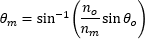 | |
| Change in Distance to Axis, Travelling through Optic (Figure 9) |  | |
| Focal Shift Caused by Refraction through Medium (Figure 9) | Exact Calculation |  |
| Paraxial Approximation |  | |
Click to Enlarge
図11:公差や温度の影響により、レンズとカメラのフランジバックが異なることがあります。レンズのフランジバックの方が短い場合には、無限遠の物体の像は焦点調整範囲外になります。このシステムでは焦点を合わせられないため、像はぼやけます。
Click to Enlarge
図10:カメラとレンズのフランジバックが同じときは、カメラのセンサ面とレンズの焦点面は完全に一致しています。無限遠の物体の鮮明な像は、システムの焦点調整範囲の一端で得られます。
カメラとレンズのフランジバック(FFD)を決めるときは、レンズとカメラのセンサ面の間にあるのは空気のみであることを仮定しています。レンズとカメラのセンサの間にウィンドウまたはフィルタ、あるいはその両方が挿入されている場合は、カメラのフランジとセンサ面の間の距離を仕様で指定されたフランジバックよりも長くする必要があるかもしれません。ウィンドウやフィルタにより光路が屈折して焦点面がより遠い位置にシフトするため、フランジバックと同じ距離では短すぎる場合があります。
レンズとカメラセンサの間の光学素子を変更するなら、焦点面のシフト量を計算し、アライメントを保つためにレンズとカメラ間の距離を調整する必要があるかどうか判断してください。焦点の合った像を得るには、適切なアライメントは必要です。理由は、光学素子を変更することで収差やその他の影響が現れ、画像品質が許容できないレベルに低下することがあるためです。
屈折による焦点移動
光が固体媒質を通るときの光路は直線です(図8)。光が焦点に集光していく過程で、光線の光軸に対する角度
平行平面を有する屈折率の高い
光学素子を通るときの光線は、同じ距離だけ空気を通る光線に比べて、光軸に向かう速さは遅くなります。光学素子から出た後の光線の光軸に対する角度は、また光学素子を通過していないときの角度θoになります。しかし、光学素子から出る光線の位置は、光学素子を通らない場合には決して通ることのない、光軸からより遠く離れた位置になります。光学素子によって屈折された光線は光軸からより遠くなるため、光軸と交差する位置は光学素子を通らない光線よりもΔfだけ先にシフトします。光学素子の厚さが増すと、2つの光線の間は広がり、Δfは増大します。
無限遠およびそれを超えた調整
カメラシステムでは、多くのアプリケーションにおいて、無限遠の物体の高品質な像を得ることが要求されます。これらの物体からの光線は平行光で、近い物体からの光線よりもよりレンズに近い位置で焦点を結びます(図10)。カメラとレンズのフランジバックは、無限遠の位置にある物体からの光線の焦点が、カメラのセンサ面と一致するように決められています。レンズに焦点の調整範囲があるときには、その範囲の一端は無限遠の物体に、もう一端はそれよりも近い物体に焦点が合うように調整されています。
温度変化や累積公差などの影響により、レンズやカメラのフランジバックが仕様を満たさない場合があります。レンズの実際のフランジバックがカメラのフランジバックよりも短いときには、カメラのシステムは無限遠の物体の鮮明な像を得ることはできません(図11)。このオフセットは、レンズとカメラセンサの間にある光学素子を取り外したときも生じることがあります。
これを補正するために、レンズによっては焦点を結ぶ物体の位置を、無限遠を「超えて」設定できるようにしています。これは物理的な距離を意味しているわけではなく、単にレンズの焦点面をより遠くまで移動できるようにしているだけです。当社のKiralux™とQuantalux®カメラに付属する調整機能付きCマウントアダプタは、必要に応じて距離を調整できるようになっています。
レンズのフランジバックがカメラのフランジバックよりも長い場合には、無限遠の物体の像はシステムの焦点調整範囲内にありますが、本来は焦点調整範囲内にあるべき近い物体がその範囲外になります。この状況は、レンズとカメラセンサの間に光学素子を挿入することで生じる場合があります。無限遠の物体のイメージングが可能であるならば、この状況はしばしば許容されることがあります。
カメラの設計例
ハーメチックシールされたTE冷却型のCマウントQuantaluxカメラには、フランジ面とセンサ面の間に18.1 mmの固定された距離があります。しかし、Cマウントカメラシステムのフランジバック(f )は17.526 mmです。フランジバックよりも長い距離が必要であることは、ハーメチックカバーにはんだ付けされているウィンドウとセンサを覆うガラスによる焦点移動を考慮すると明白です。図9の下の表に記載されている結果は、厳密な式でも近軸近似の式でも、必要な全体の距離として18.1 mmという値が得られることを示しています。
最終更新日:2020年7月31日

当社では Zelux®、Kiralux®、Quantalux®の3つのシリーズのサイエンティフィックカメラをご提供しております。Zeluxカメラは汎用的なイメージング向けで、設置面積が小さいながら高いイメージング性能を発揮します。Kiraluxカメラに搭載されているCMOSセンサには、モノクロ、カラー、近赤外(NIR)強化型、偏光検出型などの種類がございます。それらを収めた筐体には、薄型のパッシブ放熱型、小型のパッシブ放熱型、ハーメチックシールされた熱電(TE)冷却型がございます。 偏光検出型Kiraluxカメラにはマイクロ偏光子アレイが組み込まれており、ThorCam™ソフトウェアパッケージを使用すると、直線偏光度、方位角、およびピクセルレベルでの強度を表す画像を取得することができます。QuantaluxモノクロsCMOSカメラは、低光量でも使用できるように広いダイナミックレンジと低い読み出しノイズという特徴を備えています。パッシブ冷却方式のコンパクトな筐体、またはハーメチックシールされたTE冷却素子付き筐体でご用意しています。下の表では当社のカメラのラインナップの概要がご覧いただけます。
| Compact Scientific Cameras | |||||||
|---|---|---|---|---|---|---|---|
| Camera Type | Zelux® CMOS | Kiralux® CMOS | Quantalux® sCMOS | ||||
| 1.6 MP | 1.3 MP | 2.3 MP | 5 MP | 8.9 MP | 12.3 MP | 2.1 MP | |
| Item # | Monochrome: CS165MUa Color: CS165CUa | Mono.: CS135MU Color: CS135CU NIR-Enhanced Mono.: CS135MUN | Mono.: CS235MU Color: CS235CU | Mono., Passive Cooling: CS505MU1 CS505MU Mono., Active Cooling: CC505MU Color: CS505CU1 CS505CU Polarization: CS505MUP1 | Mono., Passive Cooling: CS895MU Mono., Active Cooling: CC895MU Color: CS895CU | Mono., Passive Cooling: CS126MU LP126MU(/M) Mono., Active Cooling: CC126MU Color, Passive Cooling: CS126CU LP126CU(/M) | Monochrome, Passive Cooling: CS2100M-USB Active Cooling: CC215MU |
| Product Photos (Click to Enlarge) |  |  |  | ||||
| Electronic Shutter | Global Shutter | Global Shutter | Rolling Shutterb | ||||
| Sensor Type | CMOS | CMOS | sCMOS | ||||
| Number of Pixels | 1440 x 1080 (H x V) | 1280 x 1024 (H x V) | 1920 x 1200 (H x V) | 2448 x 2048 (H x V) | 4096 x 2160 (H x V) | 4096 x 3000 (H x V) | 1920 x 1080 (H x V) |
| Pixel Size | 3.45 µm x 3.45 µm | 4.8 µm x 4.8 µm | 5.86 µm x 5.86 µm | 3.45 µm x 3.45 µm | 5.04 µm x 5.04 µm | ||
| Optical Format | 1/2.9" (6.2 mm Diag.) | 1/2" (7.76 mm Diag.) | 1/1.2" (13.4 mm Diag.) | 2/3" (11 mm Diag.) | 1" (16 mm Diag.) | 1.1" (17.5 mm Diag.) | 2/3" (11 mm Diag.) |
| Peak Quantum Efficiency (Click for Plot) | Monochrome: 69% at 575 nm Color: Click for Plot | Monochrome: 59% at 550 nm Color: Click for Plot NIR: 60% at 600 nm | Monochrome: 78% at 500 nm Color: Click for Plot | Monochrome & Polarization: 72% (525 to 580 nm) Color: Click for Plot | Monochrome: 72% (525 to 580 nm) Color: Click for Plot | Monochrome: 72% (525 to 580 nm) Color: Click for Plot | Monochrome: 61% (at 600 nm) |
| Max Frame Rate (Full Sensor) | 34.8 fps | 165.5 fps | 39.7 fps | 35 fps (CS505xx1, CC505MU, CS505MUP1), 53.2 fps (CS505xx) | 20.8 fps (CC895MU), 30.15 fps (CS895xx) | 15.1 fps (CC126MU), 21.7 fps (CS126xx and LP126xx(/M)) | 50 fps |
| Read Noise | <4.0 e="" sup="">- RMS | <7.0 e="" sup="">- RMS | <7.0 e="" sup="">- RMS | <2.5 e="" sup="">- RMS | <1 e="" sup="">- Median RMS; <1.5 e="" sup="">- RMS | ||
| Digital Output | 10 Bit (Max) | 10 Bit (Max) | 12 Bit (Max) | 16 Bit (Max) | |||
| PC Interface | USB 3.0 | ||||||
| Available Fanless Cooling | N/A | N/A | N/A | 15 °C to 20 °C Below Ambient Temperature (CCxxxMU Cameras Only) | |||
| Housing Size (Click for Details) | 0.59" x 1.72" x 1.86" (15.0 x 43.7 x 47.2 mm3) | Passively Cooled CMOS Camera TE-Cooled CMOS Camera Passively Cooled Low-Profile CMOS Camera | Passively Cooled sCMOS Camera TE-Cooled sCMOS Camera | ||||
| Typical Applications | Mono. & Color: Brightfield Microscopy, General Purpose Imaging, Machine Vision, Material Sciences, Materials Inspection, Monitoring, Transmitted Light Spectroscopy, UAV, Drone, & Handheld Imaging Mono. Only: Multispectral Imaging, Semiconductor Inspection Color Only: Histopathology | Mono., Color, & NIR: Brightfield Microscopy, Ca++ Ion Imaging, Electrophysiology/Brain Slice Imaging, Flow Cytometry, Fluorescence Microscopy, General Purpose Imaging, Immunohistochemistry (IHC), Laser Speckle Imaging, Machine Vision, Material Sciences, Materials Inspection, Vascular Imaging, Monitoring, Particle Tracking, Transmitted Light Spectroscopy, Vascular Imaging, VIS/NIR Imaging Mono. Only: Multispectral Imaging Semiconductor Inspection Color Only: Histopathology NIR Only: Ophthalmology/Retinal Imaging | Mono. & Color: Autofluorescence, Brightfield Microscopy, Electrophysiology/Brain Slice Imaging, Fluorescence Microscopy, Immunohistochemistry (IHC), Machine Vision, Material Sciences, Materials Inspection, Monitoring, Quantitative Phase-Contrast Microscopy, Transmitted Light Microscopy Mono. Only: Multispectral Imaging Semiconductor Inspection Color Only: Histopathology | Mono. & Color: Autofluorescence, Brightfield Microscopy, Electrophysiology/Brain Slice Imaging, Fluorescence Microscopy, Immunohistochemistry (IHC), Machine Vision, Material Sciences, Materials Inspection, Monitoring, Quantitative Phase-Contrast Microscopy, Transmitted Light Microscopy Mono. Only: Multispectral Imaging, Semiconductor Inspection Color Only: Histopathology Polarization Only: Inspection, Surface Reflection Reduction, Transparent Material Detection | Mono. & Color: Autofluorescence, Brightfield Microscopy, Electrophysiology/Brain Slice Imaging, Fluorescence Microscopy, Immunohistochemistry (IHC), Machine Vision, Material Science, Materials Inspection, Monitoring, Quantitative Phase-Contrast Microscopy, Transmitted Light Microscopy Mono. Only: Multispectral Imaging, Ophthalmology/Retinal Imaging, Semiconductor Inspection Color Only: Histopathology LP126xx(/M), CS126xx, and CC126MU Only: Whole-Slide Microscopy | Passive & Active Cooling: Autofluorescence, Brightfield Microscopy, Fluorescence Microscopy, Immunohistochemistry (IHC), Material Sciences, Materials Inspection, Monitoring, Quantitative Phase-Contrast Microscopy, Quantum Dots, Semiconductor Inspection, Transmitted Light Microscopy, Whole-Slide Microscopy Active Cooling Only: Electrophysiology/Brain Slice Imaging, Multispectral Imaging | |
| Posted Comments: | |
Dovlet Seyit
(posted 2024-04-17 12:15:08.12) I just recently bought CS165MU1/M
Can this stream raw data output? I want 10 files streamed and regularly update,
Best,
Seyit. jdelia
(posted 2024-04-18 04:16:41.0) Thank you for contacting Thorlabs. I reached out to you directly to clarify your inquiry and you explained you were looking for some programming interfaces and examples for our camera software. These can be found at the ThorCam download page here: https://www.thorlabs.us/software_pages/ViewSoftwarePage.cfm?Code=ThorCam David Angeley
(posted 2024-04-16 15:20:39.023) What is the CRA (Chief Ray Angle) specification for camera CS165MU - Zelus 1.6MP monochrome? ksosnowski
(posted 2024-05-09 05:26:35.0) Hello David, thanks for reaching out to Thorlabs. Unfortunately, our sensor OEM does not specify a Chief Ray Angle for this camera. I have reached out directly to discuss your application in further detail. user
(posted 2024-04-11 08:52:42.16) The python librairies are not very user friendly. I have managed (after a long time) to obtain frames by using commands similar to the "grab_single_frame.py" example. However, the frame obtained is a grayscale image (a simple matrix) despite the fact that i'm using a color cmos camera. How can one apply white balance or color correction, for example?
Thank you for your help cdolbashian
(posted 2024-04-26 02:31:07.0) Thank you for the feedback! I have contacted you directly to make sure that you indeed have found all of our documentation as well as to assist with your particular inquiry. user
(posted 2024-03-21 11:30:36.807) The steps involved in interfacing with the camera SDKs is very convoluted, poorly documented and full of bugs (I was specifically using CS165MU/M camera in python, but the problem appears to be generic). It is not clear exactly what instructions to follow, and the steps are not clearly defined, the requirements not laid out in advance. The files are scattered in various locations. Once installed, the examples did not work. Having figured out the problem, and making one particular example work, other examples did not work (it was unable to load the libraries properly), so it was necessary to combine code preamble (library importing) from the working examples with the non-working examples. Whilst I appreciate the rationale behind the file organisation, I think this is unnecessary and simply make an installation / zip file for each supported language that contains everything with *well documented and working instructions* that ensure the examples work for that language. ksosnowski
(posted 2024-03-28 04:30:04.0) Thanks for sharing this feedback with us. As we always strive to improve our documentation and eliminate any bugs, I have reached out directly to further discuss specifics which we can address for future users' implementations. Zihao Pang
(posted 2024-03-19 21:06:58.843) Hi Thorlabs,
I want to capture the image every 100ms with the exposure time 50ms. It seems that the function "Time Series" in the software ThorCam is supposed to achieve this but the minimum timing gap is 1s.
I am reaching out for the solution? Many thanks
Zihao cdolbashian
(posted 2024-03-29 02:28:06.0) Thank you for reaching out to us with this request! You are correct, the timed series function will not be able to do this. We suggest simply using either an external hardware trigger or setting the framerate to 10hz and exposure to 50ms. This would initiate a photo every 100ms, using a 50ms exposure. p p
(posted 2024-02-18 17:58:35.69) How to control DCC3240M with Matlab R2023b? Is there any matlab adaptor? cdolbashian
(posted 2024-02-21 08:31:45.0) Thank you for reaching out to us with this inquiry! The Matlab documentation files can be found in your scientific camera documentation folder when you download the ThorCam Software. I have contacted you directly with the correct path to such files. Fabian Cadiz
(posted 2024-02-14 15:21:07.213) Hi, i am trying to run the most simple python example (grab_single_frame.py) from the github repository but i get the same error as in an older comment :
"raise TLCameraError("tl_camera_open_sdk() returned error code: {error_code}\n"
thorlabs_tsi_sdk.tl_camera.TLCameraError: tl_camera_open_sdk() returned error code: 1004"
Any help is welcomed Fabian Cadiz
(posted 2024-02-14 15:20:35.217) Hi, i am trying to run the most simple python example (grab_single_frame.py) from the github repository but i get the same error as in an older comment :
"raise TLCameraError("tl_camera_open_sdk() returned error code: {error_code}\n"
thorlabs_tsi_sdk.tl_camera.TLCameraError: tl_camera_open_sdk() returned error code: 1004"
Any help is welcomed cdolbashian
(posted 2024-02-19 11:42:00.0) Thank you for reaching out to us with this inquiry. I have contacted you directly to share the issue. It seems we are missing a line of code in our github example. We are working to update this currently. Maxime Mistretta
(posted 2024-01-18 15:28:25.12) Hello,
I would like to control our Zelux Camera (C165MU1/M) with micromanager 2.0 (I have 3 or more cameras to run simultaneously). After following precisely the installation procedure of Thorlabs Manual and the Micro-Manager_README, my camera runs with Thorcam software, but with micromanager, I cannot add TSI in "hardware configuration wizard". uManager returns "Failed to load device "TSICam" from adapter module "TSI" [Device adapter "TSI" failed to instantiate device "TSICam"].
Do you have an idea of the problem ?
Thank you in advance,
Best, ksosnowski
(posted 2024-02-05 11:30:41.0) Hello Maxime, thanks for reaching out to us. The current Micromanager "Official" release does not work with our cameras. You would need to use the latest Micromanager nightly build of 2.0 which may be found here: https://download.micro-manager.org/nightly/2.0/Windows/ . The camera dll's must then be copied to the micromanager install folder. Details can be found in the micromanager readme in "C:\Program Files\Thorlabs\Scientific Imaging\Scientific Camera Support\Scientific Camera Interfaces" as the default location. I have reached out to discuss this application further. user
(posted 2024-01-02 21:08:15.703) Dear Sir or Madam, I want to control the DCC1645C by LabView. Could you please give me any examples for a beginner? Thank you. ksosnowski
(posted 2024-01-02 11:01:47.0) Hello, thanks for reaching out to Thorlabs. LabVIEW VI's for the DCxs are included in the standard Thorcam install when you select either "DCU/DCC Series Compact CMOS and CCD Cameras" or "All Cameras" options during installation. I have reached out directly to discuss your application further. suparak dunsuk
(posted 2023-12-20 14:36:43.05) I would like to ask for help. Example LapVIEW code To order the camera to take a photo and connect to ell20k/m ksosnowski
(posted 2023-12-29 11:26:56.0) Hello Suparak, thanks for reaching out to Thorlabs. ThorCam software installation will include sample VIs and libraries by default in the C:\Program Files\Thorlabs directory of your PC. The Elliptec software does include the libraries for connection however I've reached out directly to share some example VIs for this series. user
(posted 2023-12-14 09:43:17.557) Hi, I would like to know how gain affects the camera noise: the readout noise, the dark current noise, and the hot pixels. A more basic question is: what does gain do, for example in CS165MU? Does it amplify the number of photoelectrons? I appreciate your response. ksosnowski
(posted 2024-01-22 05:15:36.0) Hello, thanks for reaching out to Thorlabs. The gain control directly corresponds to an output voltage amplifier just before the analog-to-digital converter. It does not amplify the number of photoelectrons directly, but rather the voltage produced after charge-to-voltage conversion in the sensor. The analog signal, and any noise in it, is directly proportional to the gain setting. This applies to dark current noise, photon shot noise, and any other noise originating from the sensor. There should not be an increase in hot pixels due to increasing gain, but some "mild" hot pixels that could go unseen may become more obvious. I have reached out directly to discuss your application in further detail. Riccardo Panza
(posted 2023-11-22 17:46:29.64) Hi, I want to estimate the photon flux of a fluorescence imaged with a CS165MU1/M camera, but I cannot find the conversion gain ADU/e. Can you provide this number or a way to approximate it? Thank you! cdolbashian
(posted 2023-12-11 09:23:10.0) Thank you for reaching out to us with this inquiry. I have contacted you directly to discuss a potential way to estimate the photon flux. Preston Huft
(posted 2023-09-14 11:06:15.177) Hi,
I have not been able to get the python scripts from the git repository Camera_Examples to work. For example, running grab_single_frame.py returns error 1004 when tl_camera_open_sdk() is called. Is there somewhere I can find a list of the error code meanings? I couldn't find this in the camera manuals or in the git repo. I am running Python 3.8 on Windows 10 and using the CS165CU1 camera.
Thanks, Preston cdolbashian
(posted 2023-09-25 08:40:25.0) Thank you for reaching out to us Preston. After talking to you regarding this issue, it seems like there was a missing initialization line for our simple single-frame-capture script. We have provided you with the missing line of code, as well as updated the file on the repository at Github.com/thorlabs. user
(posted 2023-06-14 08:09:18.863) Hi Thorlabs,
Can we control the camera CS165MU1 using other platforms such as Matlab and Python? If we can, Could you please give us any examples for tutorials?
Thanks,
Zihao cdolbashian
(posted 2023-06-20 02:46:44.0) Thank you for reaching out to us with this inquiry. We certainly do have such examples. Our ThorCam software also downloads various programming guides and examples for various languages. I have contacted you directly to show you where these would be found. Joris B
(posted 2023-04-04 10:49:57.763) Hi, I would like to replace the coated window by an uncoated one. What is the recommended product? (600-900nm) cdolbashian
(posted 2023-04-13 10:54:58.0) Thank you for reaching out to us with this inquiry! There are many different types of windows which could be used here, but it seems like the better advice would be to let you know where to find such guidelines determining the window dimensions. Ch 7 in the camera manual specifies how to remove the window as well as the window parameters. cdolbashian
(posted 2023-04-13 10:54:58.0) Thank you for reaching out to us with this inquiry! There are many different types of windows which could be used here, but it seems like the better advice would be to let you know where to find such guidelines determining the window dimensions. Ch 7 in the camera manual specifies how to remove the window as well as the window parameters. Peter Meinhold
(posted 2023-02-28 11:08:01.133) Would it be possible to add some beam profiling tools to Thorcam, or conversely to make Beam support scientific cameras like CS165CU? It's very common to have a camera based setup, especially a microscopy setup, with a desire for some in situ quantification, at least of basic gaussian beams. jdelia
(posted 2023-03-16 12:16:51.0) Thank you for contacting Thorlabs. While this does seem like an advantageous feature, unfortunately this is not something we have implemented or have immediate plans for implementing. However, we can certainly look into this possibility in the future. user
(posted 2023-01-25 10:54:30.7) Hi, I'm currently using a DCC1545M-GL camera + LabView 2021 (new user) and I succesfully conect to the camera and start live but couldn't find a way to get an image and store the image files. I checked the examples provided and couldn't find anything useful. Thanks. GBoedecker
(posted 2023-01-30 11:06:03.0) Thank you for your feedback! In your folder C:\Program Files\Thorlabs\Scientific Imaging\Documentation\DCx Camera Documents, there is the manual DCx_DotNET_ProgInterface.pdf. You can use the "save" class from section 3.1.1.14.6. Xavier Audier
(posted 2023-01-04 15:19:10.48) Hi,
I'm having difficulties using the Camera both using the Thorcam Software and the SDK.
I need to disable/enable the device in Windows Device Manager or reinstall drivers everytime I want to use the camera.
I've tried many things but can't seem to figure out how to get it working reliably.
Any help would be appreciated.
Best,
Xavier Audier jdelia
(posted 2023-01-17 01:57:59.0) Thank you for contacting Thorlabs. We apologize for the issue you are experiencing with our camera. I have reached out to you directly to troubleshoot your issue. xuan Lin
(posted 2022-11-22 22:30:54.64) Hi THORLABS,I want to ask about the gamma value of CS165CU.Thank you! cdolbashian
(posted 2022-11-22 03:51:50.0) Thank you for reaching out to us with this inquiry. As our cameras do not allow for this non-linear style of intensity adjustment, we would have to say that the gamma value is 1. I have reached out to you directly to discuss this further. Hang Su
(posted 2022-10-24 14:18:08.32) Hi,
I want to know if there any difference between the thorcam software and thorlabs Python SDK.
I found the received images by thorcam and SDK are very different, under the same exposure time and resolution settings. Is there any post pocessing in the thorcam software? If so, how can I republicate it in the python SDK environment?
Hope further connection for more details!
Thanks,
Hang Su cdolbashian
(posted 2022-11-16 12:13:43.0) Thank you for reaching out to us with this inquiry. This discrepancy an unfortunate difference which comes from the way data is read/saved/binned from Thorcam vs Python. Depending on what you mean by "post processing", I think the answer will likely depend on your image acquisition settings within the software. I have reached out to you directly to discuss your application. Philipp Preiss
(posted 2022-08-11 15:24:18.583) Hi there,
I'm currently capturing some fluorescence images of atomic clouds on the CS165MU/M camera and would like to calibrate absolute photon flux. I cannot find any conversion gain in ADU/e on the spec sheet. Without this number, an absolute calibration can only be performed with a somewhat tedious calibration measurement. Can you provide this additional specification for the camera.
Thank you! cdolbashian
(posted 2022-08-18 02:51:15.0) Thank you for reaching out to us with this inquiry. Calculating the exact number of photons incident on this sensor is not something we expect to do with this camera. That being said, it is possible to approximate this value. I have contacted you directly to discuss this. Sergei Poltavtsev
(posted 2022-05-21 10:10:46.453) Hallo
Apparently there is a bug in offered LabView driver. Repeatedly observed the following behavior of the supplied LabView example (as well as a custom software written with this driver): Launching of a program results in LabView crash after several (~10times) successful starts. It is tested on LabView2020+2021, on various PCs. If software addresses two such cameras, the number of successful launches shortens twice (~5-6). Zihao Pang
(posted 2022-05-16 21:21:34.18) Hi Thorlabs,
We've recently purchased your camera CS165MU1 and are wondering if it can automatically do the capturing with a fixed delay? For example, we want to take a picture every 100 ms until I had 100 pictures.
Many thanks,
Zihao jdelia
(posted 2022-05-19 10:26:13.0) Thank you for contacting Thorlabs. The CS165MU1 allows for control of the framerate within the ThorCam software. If the exposure is low enough, then you can set the framerate to 10Hz and a "frames per trigger" value of 100. This will provide 100 frames in a single click at 10Hz. user
(posted 2022-01-19 17:45:55.69) The camera gives the below error in continuous running mode after about 100 frames or immediately if illumination changes:
TLCamera2:tl_camera_close_camera:Error:tl_camera_handle=1350894998448, command='stop', command_size_bytes_including_any_null_terminator = 5, data_size_bytes = 0', response_size_bytes_up_to_1024 = 1024; Error setting data. Error: Communication failure.
ThorCam ver: 3.6.1.4, Cam firmware ver: 0.9.6
I was trying to use the camera with micro-manager but also get an error of ' failed in instantiate the device'.
Any help on getting the camera working properly would be greatly appreciated. Thank you. Oanh Ho
(posted 2022-01-19 07:26:19.697) Please let us know the price and the lead time for this camera DCC1545M (USB 20 CMOS Camera, 1280x1024, Monochrome Sensor) YLohia
(posted 2022-01-19 08:32:49.0) Thank you for contacting Thorlabs. The DCC1545M has been obsoleted and is no longer sold. My apologies for any issues caused by this. We suggest looking into its replacement, the CS165MU, instead which has a unit price of $448.05/pc and is currently in stock. Madhav Gupta
(posted 2021-11-15 05:45:00.37) Hi. I am using the CS165MU1/M camera for my application. I wanted to ask if this device is compatible with Linux? I wanted to try and use this camera with a Raspberry Pi, so wanted to know if it is compatible with Linux. Please let me know as soon as possible.
Thanks!
Best Regards,
Madhav Gupta jgreschler
(posted 2021-11-15 04:22:53.0) Thank you for reaching out to Thorlabs. The ThorCam software is exclusive to Windows, however the SDK is Linux compatible and supports all CS cameras except the CS135. You can find the download link for the Linux SDK here https://www.thorlabs.us/software_pages/ViewSoftwarePage.cfm?Code=ThorCam Keisuke Kaneshima
(posted 2021-10-11 11:38:11.85) Hello. I’m trying to use CS165MU/M with LabVIEW. I got several error messages when I ran “TLCamera Main.vi” in Windows SDK and Doc. for Scientific Cameras.
1. The class and method of the invoke node in “Open TLCameraSDK.vi” were not set properly, and the program could not load the camera. After I manually set them (Assembly: Thorlabs.TSI.TLCamera(2.0.0.0), Objects: TLCameraSDK), the program became to be able to load the camera.
2. Then I got the following message:
“Error 1172 occurred at Property Node (Arg :1) Error accessing property Thorlabs.TSI.TLCameraInterfaces.ITLCamera.TriggerPolarity, (System.Reflection.TargetInvocationException: Inner Exception: System.InvalidOperationException: TLCamera2: tl_camera_set_trigger_polarity: Error: tl_camera_handle=1920755625488, command='hwtrig', command_size_bytes_including_any_null_terminator = 7, data_size_bytes = 0', response_size_bytes_up_to_1024 = 1024: Invalid command' Error: Firmware-reported error.)
Possible reason(s):
LabVIEW: (Hex 0x494) A .NET exception occurred in an external assembly. For information about correcting this error, copy the following exception (in bold), and search the Microsoft Developer Network (MSDN) Web site or the Web for a possible explanation.
System.InvalidOperationException in Set Trigger Settings.vi->TLCamera Main.vi”
How can I fix this?
Thank you. azandani
(posted 2021-10-18 04:24:09.0) Hello Keisuke, thank you for contacting Thorlabs. We will reach out to you directly to troubleshoot. R EHU
(posted 2021-04-13 05:56:44.72) I am experiencing problems working with ThorCam software (to control a Thorlabs CMOS camera) simultaneously with Kinesis or APT software to control Thorlabs stepper motors. The two softwares seem to work correctly when they run alone, but when doing it simultaneously the camera never works. Is there an incompatibility problem? YLohia
(posted 2021-04-14 10:10:36.0) Thank you for contacting Thorlabs. We're sorry to hear about the issues you're experiencing. Could you please provide the following information?
-Computer make, model, and processor
-Windows Revision and Bit version
-Thorcam, Kinesis, and APT versions
-Part numbers of the stepper motor and controller
-Is the camera and motion control hardware being used on the same Bus? For example, adjacent ports on a PC will often be on a shared Bus.
-Are you using a USB hub?
-Are you using the Zelux with the Thorlabs cable that is included with the camera?
If you have any other information about your system that you feel may be relevant, we would be interested in getting this as well. Information such as other connected devices, concurrently running software, or present virtual machines could also be useful. I have reached out to you directly to troubleshoot this further. Perry Ellis
(posted 2021-03-10 11:46:39.023) Hi,
I'm controlling the CS165MU1 via micromanager 2.0 I notice that I have no option to tune the gain from within micromanager. The micromanager device adapter shows functions and settings to call the gain. In addition, the ThorCam 3.5.1 software can control the camera gain. I was told that y'all maintain the device adapter codes - is there an easy way to get access to the gain within uManager? Thanks. YLohia
(posted 2021-03-15 11:19:33.0) Hello, thank you for contacting Thorlabs. Unfortunately, gain has not been setup internally for our device adapter, but we have added that as an item to our work queue. Until then, there is not a way to control gain from within Micromanager. ALİ GOKMEN
(posted 2021-01-27 23:08:22.52) I have Zelux camera CS165MU/M. I could not get any image on Live Window of ThorCam software with start/stop and snapshot buttons. I am not familiar with scientific cameras. May I ask your guidance to capture an image with Zelux camera.
Info about camera and windows:
CS165MU/M , S/N: 09443.
Camera is interfaced to PC through USB 2.0 port.
Windows 10: 6 GB RAM
Processor: Intel core i5 CPU, 3.1 GHz
64 bit operating system. YLohia
(posted 2021-02-01 10:04:52.0) Hello Ali, thank you for contacting Thorlabs.
1. What version of ThorCam are you using?
2. What's the firmware version on your CS165MU/M?
3. Could you please send some screenshots of your Thorcam window showing the issue?
4. Is the camera connected directly to your computer or are you connecting it to a USB hub?
5. Have you tried using this camera on a different computer with a Thorcam installation?
I have reached out to you directly to troubleshoot further. YLohia
(posted 2021-02-01 10:04:52.0) Hello Ali, thank you for contacting Thorlabs.
1. What version of ThorCam are you using?
2. What's the firmware version on your CS165MU/M?
3. Could you please send some screenshots of your Thorcam window showing the issue?
4. Is the camera connected directly to your computer or are you connecting it to a USB hub?
5. Have you tried using this camera on a different computer with a Thorcam installation?
I have reached out to you directly to troubleshoot further. Yuhao Yuan
(posted 2021-01-26 11:12:10.45) When I connected the CS165CU1 to the computer, I could start capture for a few seconds. Then it died with a window saying 'An error communicating with the camera or acquiring data occurred'. I could reconnected the camera by re-plugging the cable but was not able to capture anymore unless I restarted my computer.
Please advise.
Thank you YLohia
(posted 2021-01-26 03:09:34.0) Hello, thank you for contacting Thorlabs. We're sorry to hear about the issues you're experiencing with the CS165CU1. Would you be able to tell us your Windows machine specs, ThorCam software version, and CS165CU1 firmware version number? We have an updater on the download page that fixed some bugs with that camera. Please ensure that you're using the latest version of the ThorCam software. Are you using this on a USB hub? We have seen this sort of issue happen previously when using 3rd party USB ports/hubs -- please be sure to use USB3-PCIE from our website in this case. I have reached out to you directly to troubleshoot this further. GT KIM
(posted 2020-09-18 04:29:51.09) HI,
I wonder relation between exposure time and frame speed in detail of this camera. For instance, I want to get image during 4 sec with 50ms exposure time when one external trigger occurs. So I change Frames per Trigger setting to 80 frames. Then I expect total 80 frames in 4 seconds of imaging time with 50ms exposure time but actual imaging time is more than 4 seconds. llamb
(posted 2020-09-22 01:42:15.0) Thank you for contacting Thorlabs. It sounds like your case is when frames/trigger is not set to continuous mode, so the exposure time and readout time are sequential (non-overlapped). In continuous mode, all but the first exposure are overlapped with readout. If elapsed time is most important, then I would recommend setting the number of frames per trigger to "continuous" and stopping the acquisition after the desired elapsed time. Pawel Czuma
(posted 2020-04-10 06:32:14.99) Dear Sir/Madam,
On RAW data spec of CS165MU1/M I see big quantum efficiency 50,396% at 235nm (I suppose after removal of AR-Coated Window). Could You send me UV QE spec of this camera in range between 200 to 300nm. I am interested especially in range 270-249nm.
Do You have any of Your camera working in such spectral range. Do You have imaging objective on working in such spectral range.
Thank You
Best Regards,
dr Pawel Czuma, Eng
Task Manager PolFEL YLohia
(posted 2020-04-10 02:32:47.0) Hello Pawel, thank you for contacting Thorlabs. We recommend our UV-enhanced 340UV-USB camera for that wavelength range. Our line of UV objectives can be found here : https://www.thorlabs.com/newgrouppage9.cfm?objectgroup_id=3271. I have reached out to you to discuss your application in more detail. |
Camera Selection Tool
Reset Parametersof 31 Products Shown
Select Parameters
Select Applications
of 31 Products Shown
| Item Number | Sensor Type | Optical Format | Electronic Shutter | Pixel Size | Max Frame Rate | Read Noise | Digital Output | Cooling | Housing Dimensions |
|---|

 ズーム
ズーム| Key Specificationsa | ||||
|---|---|---|---|---|
| Item # | CS165MU(/M) | CS165MU1(/M) | CS165CU(/M) | CS165CU1(/M) |
| Sensor Type | Monochrome CMOS | Color CMOS | ||
| Hardware Trigger/Strobe | No | Yesb | No | Yesb |
| Peak Quantum Efficiency (Click for Graph) | 69% at 575 nm | 65% at 535 nm | ||
| Removable Optic | AR-Coated Window, Ravg < 0.5% per Surface (400 - 700 nm) | IR Blocking Filter | ||
| Mounting Features | Imperial: Two 1/4"-20 Taps for Post Mounting, 30 mm Cage Compatible Metric: Two M6 Taps for Post Mounting, 30 mm Cage Compatible Taps are on Adjacent Sides of the Housing | |||
Zeluxカメラの取付機能 | |||
 Click to Enlarge SM1ネジ付き開口部にSM1レンズチューブを取り付けたZeluxカメラ | 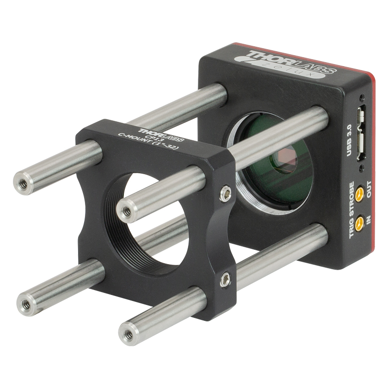 Click to Enlarge ケージロッド用の4つのタップ穴(#4-40)を用いて30 mmケージシステムを取り付けられます。写真では、Cマウントネジ付きケージプレートCP13(/M)が取り付けられています。 | 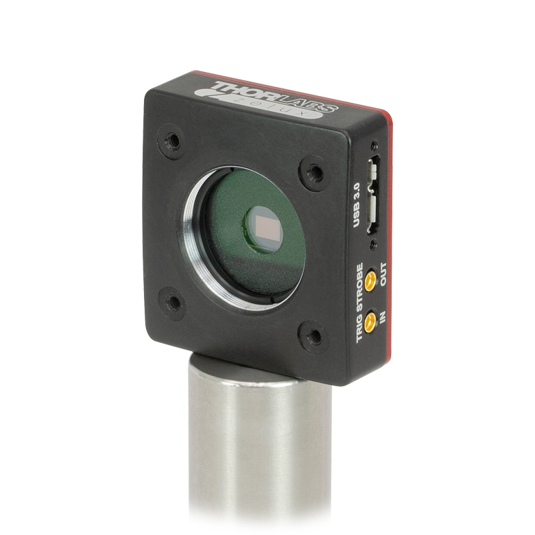 Click to Enlarge ZeluxカメラCS165MU1(/M)は、筐体底部の1/4"-20タップ(M6)穴を用いてØ1インチ(Ø25 mm~Ø25.4 mm)台座付きポストに取り付けられます。 | |

 ズーム
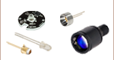
ズームZelux®カメラには、USB 3.0 Micro B - Aケーブル(長さ3.0 m)が1本と、スナップオン式レンズキャップSM1EC2Bが1個付属します。また、ZeluxカメラCS165MU1/MおよびCS165CU1/Mには外部トリガ信号用のコネクタが付いており、MMCX-BNCケーブル(CA3339)が2本付属します。さらに下記のアクセサリをご用意しています。
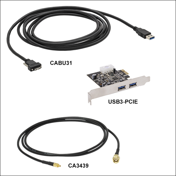
USB 3.0カメラ用アクセサリ(CABU31、CABU32、USB3-PCIE)
当社ではカメラをPCに接続するためのUSB3.0 A-Micro B(ストレート)ケーブルCABU31をご用意しております(なお、各カメラには、ストレートコネクタ付きのケーブルが1本付属しています)。ケーブルの長さは3 mです。Micro Bのコネクタの両側にはカメラのタップ穴に対応するネジが付いており、USBケーブルをカメラの筐体に固定できます。当社ではL型のMicro-Bコネクタが付いたケーブルCABU32もご用意しております。なお、こちらのコネクタは、カメラのハードウェアトリガのコネクタをブロックしますのでご留意ください。USB 3.0カメラを動作させるときはカメラに付属しているUSB 3.0ケーブルまたはCABU31をお使いいただき、固定用のネジをしっかりと締めることを強くお勧めいたします。高速でデータ転送を行うため、一般のUSB 3.0ケーブルを使用すると問題が発生する場合があります。
すべてのZeluxカメラは、ノート型PCやデスクトップ型PCのUSB 3.0ポートに直接接続できます。ホスト側のUSB 3.0ポートは多くの場合は青色ですが、黒色の場合もあります。また、一般にSuperSpeedを表す「SS」マークが付いています。Intel USB 3.0コントローラを内蔵していないPC向けに、USB 3.0用PCIeカードを別売りでご提供しております。なお、USBハブを使用すると性能に影響を与える場合がありますのでご注意ください。PCとは専用ケーブルで接続することをお勧めいたします。
トリガ信号およびストローブ信号用ケーブル(CA3339、CA3272、CA3439)
MMCX-BNCケーブルCA3339およびCA3272の長さは、それぞれ1 mと1.8 mです。MMCX-SMAケーブルCA3439の長さは1 mです。いずれもオス-オスコネクタ付きのRG-174同軸ケーブルです。周波数範囲はDC~6 GHz、インピーダンスは50 Ω、最大電圧は170 Vです。詳細は製品紹介ページをご覧ください。
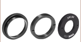
| Adapter Compatibility with Zelux Cameras | ||
|---|---|---|
| Adapter Item # | C-Mount Lenses | CS-Mount Lenses |
| SM1A10 | - |  |
| SM1A10Z | | - |
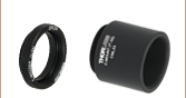
CおよびCSマウントレンズ用アダプタ(SM1A10、SM1A10Z)
当社ではCおよびCSマウントレンズをZeluxカメラに取り付けるためのアダプタもご用意しております。アダプタSM1A10およびSM1A10ZにはCマウント用内ネジとSM1外ネジが付いており、各ZeluxカメラのSM1ネジ付き開口部に取り付けることができます。CSおよびCマウントのネジ規格はどちらも1.00"-32ですが、フランジ焦点距離(FFD)はCマウントの方がCSマウントよりも5 mm長くなっています。Zeluxカメラに使用するとき、アダプタSM1A10を用いればCSマウントレンズに適したFFDが得られ、アダプタSM1A10Zを用いればCマウントレンズに適したFFDが得られます。