 Products Home
偏光カメラ、5.0メガピクセルモノクロCMOSセンサ
- Polarization-Sensitive Monochrome CMOS Camera
- On-Chip Wire Grid Polarizer Array
- High Quantum Efficiency & Low <2.5 e- Read Noise
- C-Mount Compatible with 2/3" Optical Format
CS505MUP1
Monochrome
Polarization Camera
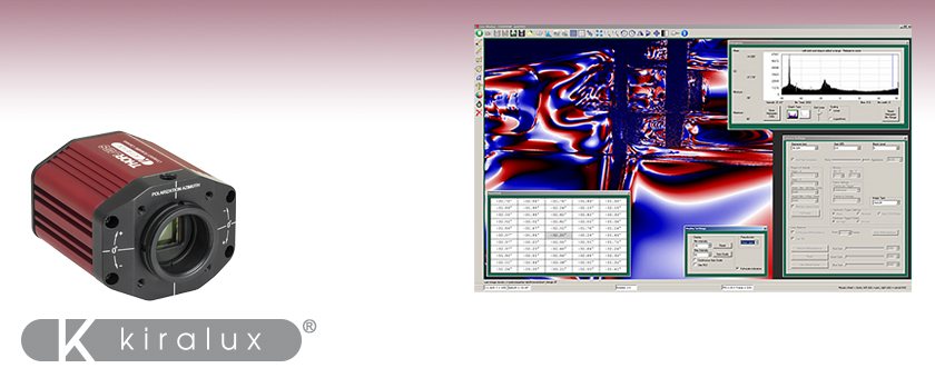
ThorCam software showing the calculated azimuth / angle of linear polarization (AoLP) of plastic safety goggles using the CS505MUP1 camera and polarized light. The captured image has a pseudocolor effect applied as a visualization aid. Click here to download the full-resolution image and see the Polarization tab below for more information.


Please Wait
用途例
- 材料検査
- 応力検査
- 探傷試験
- コントラスト向上
- 透明材料の検知
- 表面反射の測定
- 深度マッピング
| Scientific Camera Selection Guide |
|---|
| Zelux® CMOS (Smallest Profile) |
| Kiralux® CMOS |
| Kiralux Polarization-Sensitive CMOS |
| Quantalux® sCMOS (< 1 e- Read Noise) |
Feedback? ご質問やお見積りのご要望は |
特長
- 4方向ワイヤーグリッド偏光子アレイが組み込まれたモノクロの5.0メガピクセルCMOSセンサ
- 高い量子効率:525~580 nmで72%(典型値)
- ピクセルサイズ:3.45 µm x 3.45 µm
- 冷却ファンのないパッシブ型の温度管理により、振動や画像のブレを発生させずに暗電流を低減
- 読み出しノイズ<2.5 e-RMS(未処理画像)
- トリガモードおよびバルブモード
- グローバルシャッタ
- USB 3.0インターフェイス
- Windows® 7、10、および11用のThorCam™ソフトウェア
- 偏光イメージングモードの種類
- Intensity(光パワー)/ストークスベクトルS0
- Degree of Linear Polarization(直線偏光度)(DoLP、下の動画で紹介しています)
- Azimuth(方位角)/直線偏光角度(AoLP、上の画像でご覧いただけます)
- Unprocessed(未処理の生画像)
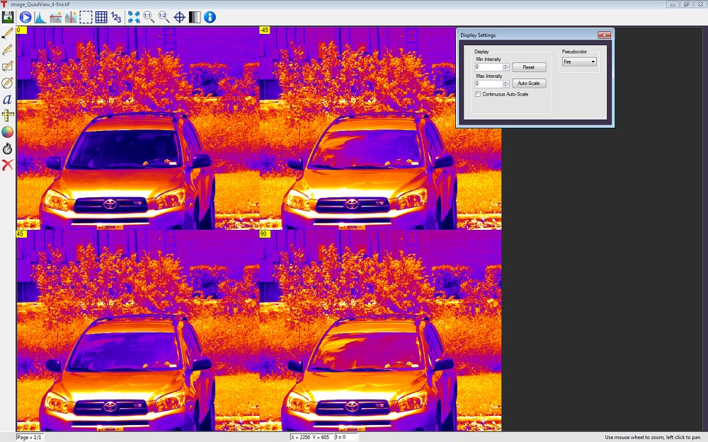
- QuadView(未処理、偏光により4分割)
- SDKならびにプログラミングインターフェイスが下記をサポート
- C、C++、C#、Python、Visual Basic .NET API
- LabVIEW、MATLABならびにµManagerサードパーティーソフトウェア
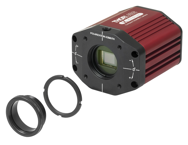
- 方位角は筐体に刻印
- 開口部はSM1ネジ付き、標準的なCマウント用アダプタが付属
- 30 mmケージシステムに取付け可能
- ポスト取付け用1/4"-20タップ穴
当社の偏光検出型カメラKiralux®は、オンチップのマイクロレンズとフォトダイオードの間に偏光子アレイを有する、5.0メガピクセルモノクロCMOSセンサです。ワイヤーグリッド偏光子アレイは、透過軸が0°、 45°、-45°、90°の4種類の偏光子の繰り返しパターンで構成されており、センサーチップのマイクロレンズアレイとフォトダイオードの間に置かれています。この偏光子アレイと画像処理ソフトウェアにより、画素の大きさレベルで偏光度(DoLP)、方位角、および強度を表す画像を生成することができます。これらの機能を利用することで、例えば応力誘起の複屈折性検出、表面反射の測定、材料検査など、偏光を利用した多くの先進技術を実現できます。筐体にはアライメントしやすいよう偏光の方位が刻印されています
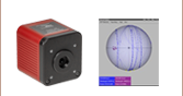
この偏光度 (DoLP、フォールスカラーで表示) の動画は、プラスチック製のハンドルに偏光した光を照射し、そのハンドルの曲がる様子を偏光カメラCS505MUP1で観察したものです。ThorCam、ImageJ、または他のサイエンティフィックイメージングソフトウェアを使用することで、このようなフル解像度の16ビット画像をご覧いただくことができます。一般的なイメージビュワーではこれらのイメージは正しく表示されません。
またこのカメラの読み出しノイズは非常に小さく、感度が高いため、要件の厳しいイメージング用途にも適しています。グローバルシャッタにより全視野を同時に走査するため、高速に移動する物体のイメージングも可能です。コンパクトな筐体はセンサの温度管理がパッシブに行われるように設計されており、そのため冷却ファンや熱電冷却(TEC)素子を使用せずに暗電流を低減することができます。
カメラ本体の上部に刻印されている線はセンサのおおよその軸位置を示しています。各CMOSカメラにはUSB 3.0インターフェイスが付いており、ほとんどのPCに接続できます。また、Windows 7、10および11で動作するThorCamソフトウェアも付属しています。開発者の方はフル機能のAPIおよびSDKをご利用いただけます。最新のソフトウェア、ファームウェア、およびプログラミングインターフェイスはこちらのThorcam Softwareのページからダウンロードいただけます。
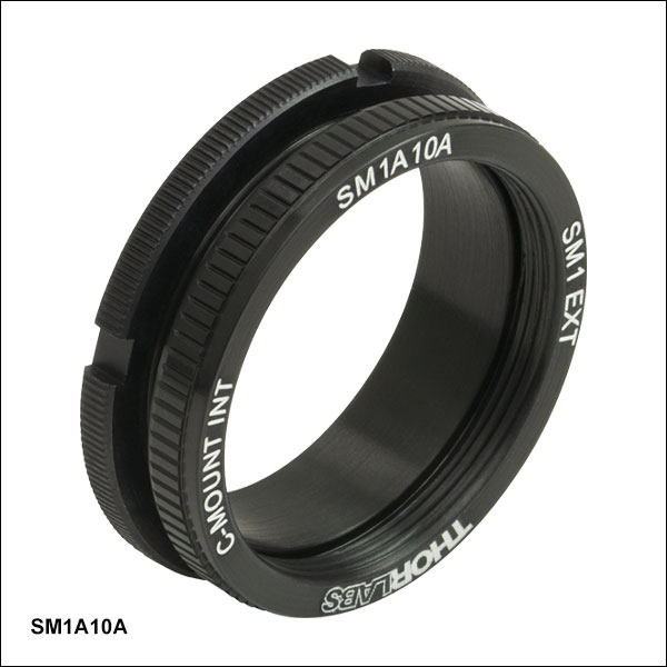
カメラの開口部にはØ25 mm~Ø25.4 mm(Ø1インチ)レンズチューブや SM1ネジ付きアダプタが取付け可能なSM1ネジが付いています。ここには調整可能なCマウントアダプタが取付け済みで出荷されるため、到着後すぐに様々な顕微鏡やマシンビジョン用カメラレンズ、Cマウントエクステンションチューブなどを取り付けることができます。交換用のCマウントアダプタSM1A10Aは別売りでご用意しております(下記参照)。
モノクロカメラには透明なウィンドウが付いています。この光学素子は取り外すことができ、カメラのCマウントアダプタを使用すると厚さ1.27 mmまでのØ25 mm~Ø25.4 mm(Ø1インチ)光学素子に置き換えることができます。このアダプタを使用しないときは、フィルタの最大厚さは4.4 mmとなります。
4つのタップ穴からは、当社の30 mmケージシステムを直接取り付けることが可能です。当社では、30 mmケージシステムやSM1レンズチューブシステムへのカメラの着脱を素早く行うのに便利なCマウントネジ付きアリ溝アダプタもご用意しております。また、筐体の両側にある2つの1/4"-20タップ穴には、インチ規格のØ1インチ台座付きポストまたはピラーポストを取り付けられます。こちらのCMOSカメラは小型であるうえにマウントの仕方にも柔軟性があり、市販の顕微鏡を用いたイメージングシステムのほか、自作のシステムに組み込むのにも適した製品です。
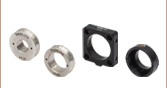
カメラの取付機能 | ||||
 Click to Enlarge Cマウントアダプタおよびロッキングリングを取り外すとSM1ネジが露出します。このネジを用いると、当社の標準的な部品を使用してカスタム仕様のアセンブリを構築できます。 | 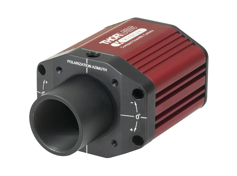 Click to Enlarge 開口部のSM1ネジを用いてSM1レンズチューブを取り付けられます。 |  Click to Enlarge ケージロッド用の4つのタップ穴(#4-40)を用いて30 mmケージシステムを取り付けられます。この写真では、Cマウントネジ付きケージプレートCP13(/M)を取り付けています。 | ||

| Item # | CS505MUP1 |
|---|---|
| Sensor Type | Monochrome CMOS with Wire Grid Polarizer Arraya |
| Effective Number of Pixels (Horizontal x Vertical) | 2448 x 2048 |
| Imaging Area (Horizontal x Vertical) | 8.4456 mm x 7.0656 mm |
| Pixel Size | 3.45 µm x 3.45 µm |
| Optical Format | 2/3" (11 mm Diagonal) |
| Max Frame Rate | 35 fps (Full Sensor) |
| ADCb Resolution | 12 Bits |
| Sensor Shutter Type | Global |
| Peak Quantum Efficiency | 72% from 525 to 580 nm (Typical) |
| Read Noise | < 2.5 e- RMSc |
| Full Well Capacity | ≥10 000 e- |
| Exposure Time | 0.027 ms to 14235 ms in ~0.013 ms Increments |
| Vertical and Horizontal Digital Binning | 1 x 1 to 16 x 16 |
| Region of Interest (ROI) | 260 x 4 Pixelsd to 2448 x 2048 Pixels, Rectangular |
| Dynamic Range | Up to 71 dB |
| Lens Mount | C-Mount (1.000"-32) |
| Mounting Features | Two 1/4"-20 Taps for Post Mounting 30 mm Cage Compatible |
| Removable Optic | Window, Ravg < 0.5% per Surface (400 - 700 nm) |
| USB Power Consumption | 3.6 W @ 35 fps (Full Sensor ROI) |
| Ambient Operating Temperature | 10 °C to 40 °C (Non-Condensing) |
| Storage Temperature | 0 °C to 55 °C |
| Example Frame Rates at 1 ms Exposure Timea,b | |
|---|---|
| Region of Interest | Frame Rate |
| Full Sensor (2448 x 2048) | 35 fps |
| Half Sensor (1224 x 1024) | 68 fps |
| ~1/10 Sensor (260 x 208) | 290 fps |
| Minimum ROI (260 x 4) | 887.6 fps |
Click to Enlarge
Mechanical Drawing of the Kiralux®カメラの筐体の概略図
Click to Enlarge
生データはこちらからダウンロードいただけます。
このグラフはオンチップの4方向ワイヤーグリッド偏光子アレイの消光比(ER)を示しています。消光比(ER)は、評価する上で十分な偏光比を有する直線偏光を入射したときに得られる、最大透過率の最小透過率に対する比率です。偏光子の透過軸に対して入射光の偏光方向が平行のときに最大透過率が得られ、そこから偏光子を90°回転させると最小透過率が得られます。
Click to Enlarge
ワイヤーグリッド偏光子アレイは、透過軸が0°、 45°、-45°、90°の4種類の偏光子の繰り返しパターンで構成されており、センサーチップのマイクロレンズアレイとフォトダイオードの間に置かれています。偏光子をマイクロレンズアレイの前面に配置するのに対して、マイクロレンズとフォトダイオードの間に組み込むことで隣接する偏光子間のクロストークを最小化することができ、アライメントの精度が向上します。
Click to Enlarge
4方向ワイヤーグリッド偏光子アレイは、センサーチップのマイクロレンズアレイとフォトダイオードの間に置かれています。
Click to Enlarge
ワイヤーグリッド偏光子ではワイヤに垂直な電界ベクトルの光は透過し、ワイヤに平行な電界ベクトルの光は反射します。
偏光カメラの特長
- 4方向ワイヤーグリッド偏光子アレイを組み込んだCMOSセンサ
- ThorCam™ ソフトウェアによる偏光イメージングモードの種類
- Intensity(光パワー) / ストークスベクトルS0
- Degree of Linear Polarization(直線偏光度、DoLP)
- Azimuth(方位角)/直線偏光角度(AoLP)
- Unprocessed(未処理の生画像)
- QuadView(未処理、偏光により4分割)
偏光カメラCS505MUP1のイメージセンサには、像の直線偏光状態を検出するためのマイクロ偏光子アレイが組み込まれています。偏光子はマイクロレンズとフォトーダイオードの間に組み込まれています。偏光子アレイをマイクロレンズアレイの前面に置いたときと比較して、この配置によりクロストークが最小化され、また偏光子の方向とそれに対応するピクセルとのアライメント精度も向上します。偏光子アレイはセンサーの上に直接作成されたワイヤーグリッド偏光子で形成されており、モザイク状のパターンで配列されています(右端の図をご覧ください)。これらの偏光子は平行な金属ワイヤのアレイで構成されており、ワイヤに垂直な電界ベクトルの光は透過し、ワイヤに平行な電界ベクトルの光は反射します(上の図をご覧ください)。各ピクセルは45°、0°、 45°、-90°の4種類の直線偏光子のうちの1つで覆われる形になります。これらのピクセルからの出力を用いて、各ピクセルに入射された光の3つの偏光パラメータである強度、偏光度、および方位角を算出します。
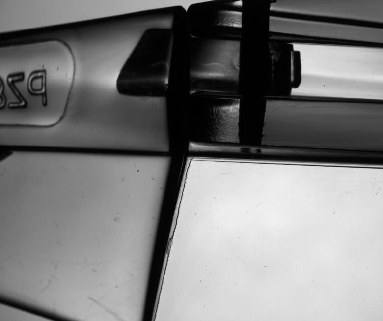
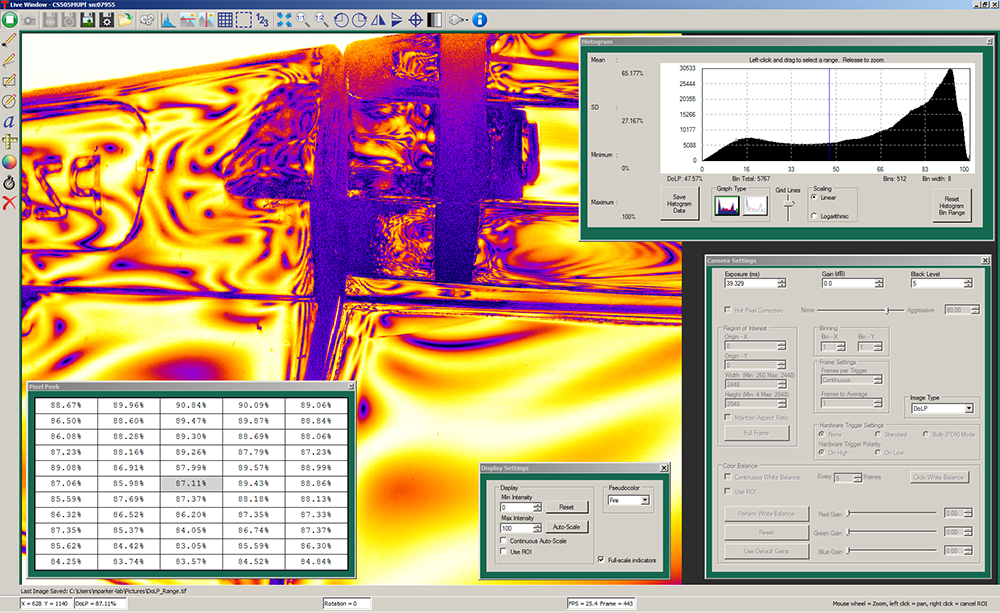
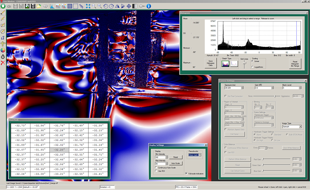
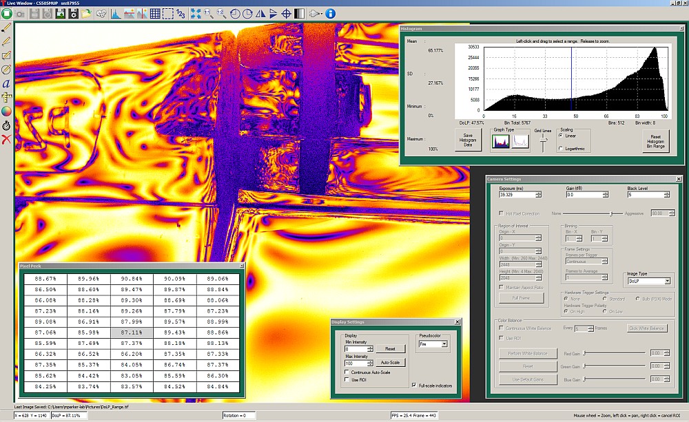
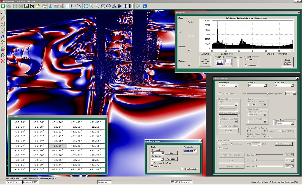
下の図では、プラスチック製のレーザ保護メガネのヒンジ部分の画像と、車のウィンドシールドからの反射光の測定についてご紹介しています。 左上はIntensity(強度)モードで取得した画像で、右上と左下のソフトウェアのスクリーンショットはDoLP(偏光度)およびAzimush(方位角)のイメージモードで取得しています。偏光カメラの操作と偏光画像についての詳細は、ThorCamユーザーガイド(ソフトウェア関連資料に付属。下の赤い(![]() )アイコンをクリックしてダウンロードも可能です)をご参照ください。なお、画像は選択されたモードで保存されますが、そのモードにおいて適用されたすべての処理情報も保存されます。画像処理を別個に行いたい場合は、Unproceesed(未処理)あるいはQuadView(4分割)モードで保存してください。
)アイコンをクリックしてダウンロードも可能です)をご参照ください。なお、画像は選択されたモードで保存されますが、そのモードにおいて適用されたすべての処理情報も保存されます。画像処理を別個に行いたい場合は、Unproceesed(未処理)あるいはQuadView(4分割)モードで保存してください。
下でダウンロードできるフル解像度画像のような高ビット深度の画像は、ThorCam、ImageJ、または他のサイエンティフィックイメージングソフトウェアを使用してご覧いただくことができます。一般的なイメージビュワーではこれらのイメージは正しく表示されません。

Click to Enlarge
ThorCam画面、QuadView(4分割)モード
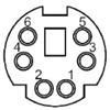
カメラ背面パネルのコネクタの配置図
I/Oコネクタのピン配列については、下記の補助(I/O)コネクタをご参照ください。
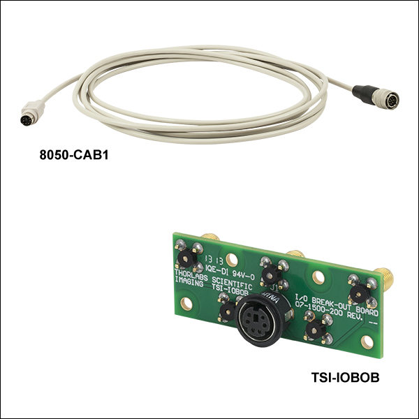
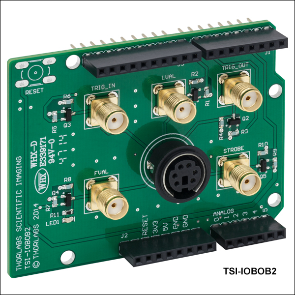
ブレイクアウトボードTSI-IOBOBおよびTSI-IOBOB2のコネクタ
Click to Enlarge
TSI-IOBOB
Click to Enlarge
TSI-IOBOB2
| TSI-IOBOBおよびTSI-IOBOB2のコネクタ | コネクタ8050-CAB1 | カメラの補助(I/O)ポート |
|---|---|---|
 メス型6ピン Mini Dinメス型コネクタ |  オス型6ピン Mini Dinオス型コネクタ (ケーブルのTSI-IOBOB側端)  オス型12ピンHiroseコネクタ(ケーブルのカメラ側端) |  メス型12ピンHiroseコネクタ(カメラの補助ポート) |
補助(I/O)コネクタ
カメラとブレイクアウトボードのコネクタはメス型で、カメラには12ピンHiroseコネクタ、ブレイクアウトボードには6ピン Mini Dinコネクタが付いています。ケーブル8050-CAB1の両端には何れもオス型のコネクタが付いており、カメラには12ピンのコネクタ、ブレイクアウトボードには6ピン Mini Dinコネクタを接続します。ピン1、2、3、5、6はそれぞれブレイクアウトボード上のSMAコネクタの中心ピンに接続され、ピン4(接地端子)は各SMAコネクタの筐体に接続されます。8050-CAB1では使用されていないI/O機能をご入用の場合は、カメラがCEならびにFCCコンプライアンスに準拠するようシールドケーブルを加工する必要があります。詳しくはカメラのマニュアルをご覧ください。
| Camera I/O Pin # | TSI-IOBOB and TSI-IOBOB2 Pin # | Signal | Description |
|---|---|---|---|
| 1 | - | GND | カメラ信号用アース |
| 2 | - | GND | カメラ信号用アース |
| 3 | - | GND | カメラ信号用アース |
| 4 | 6 | STROBE_OUT (Output) | 連続多重露光モードで動作しているとき、実際にセンサが露光されている間はHighとなるLVTTL出力。一般に、外付けストロボやその他のデバイスをカメラと同期させるのに使用されます。 |
| 5 | 3 | TRIGGER_IN (Input) | 露光開始のトリガに使用されるLVTTL入力。極性(HighからLow、またはLowからHigh)はThorCamで選択でき、初期値はLowからHighになっています。 |
| 6 | 1 | LVAL_OUT (Output) | 「Line Valid(ライン有効)」の略。アクティブハイ(正論理)のLVTTL信号で、各ラインのピクセルが有効のときにアサートされます。各ライン間ならびに各フレーム間ではLowに戻ります。 |
| 7 | - | OPTO I/O_OUT STROBE (Output) | 光学的に絶縁された出力信号。2.5 V~20 Vの外部電圧に対するプルアップ抵抗を付けてください。このプルアップ抵抗は、ピンに流れる電流が40 mA以下に制限できるものにしてください。ピン7に出力される信号はSTROBE_OUT信号に初期設定されていますが、これは実質的にトリガ出力信号になります。 |
| 8 | - | OPTO I/O_RTN | OPTO I/O_OUT出力およびOPTO I/O_IN入力のリターン接続。この端子は、OPTO I/O_OUT信号の場合はプルアップ電源に、OPTO I/O_IN信号の場合は駆動電源に接続する必要があります。. |
| 9 | - | OPTO I/O_IN (Input) | トリガ露光に使用される光学的に絶縁された入力信号。3.3 V~10 Vの駆動電源の供給が必要。内部の直列抵抗により、10 Vにおいて電流は50 mA以下に制限されます。 |
| 10 | 4 | GND | カメラ信号用アース |
| 11 | - | GND | カメラ信号用アース |
| 12 | 5 | FVAL_OUT (Output) | 「Frame Valid(フレーム有効)」の略。ライン読出しがアクティブ時にはHigh、フレーム間ではLowに戻るLVTTL出力信号。 |
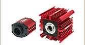
Click to Enlarge
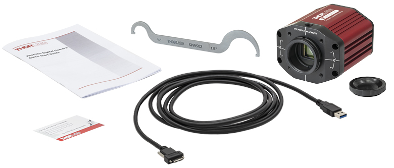
偏光カメラKiralux CS505MUP1と付属するアクセサリ
カメラには下記のアクセサリが付属します。
- USB 3.0ケーブル(Micro B-A、外観が写真と異なる場合があります)
- 光学アセンブリを緩めるためのレンチ(型番SPW502)
- レンズマウント用ダストキャップ
- クイックスタートガイド、マニュアルダウンロード情報カード
ThorCam™
ThorCamは強力な画像取得ソフトウェアパッケージで、当社のカメラを32ビット版または64ビット版のWindows®7、10または11で使用できるように設計されています。直観的で使いやすいグラフィカルインターフェイスによるカメラ制御や、イメージの取得・再生が可能です。シングルイメージキャプチャとイメージシーケンスをサポートしています。ソフトウェアの基本的な機能については、下記のスクリーンショットをご覧ください。
アプリケーションプログラミングインターフェイス(API)とソフトウェア開発キット(SDK)が付属しているため、組み込み用途(OEM用途)向けや開発業者によるカスタムアプリケーションの開発も可能です。SDKは、C、C++、C#、Python、Visual Basic .NETなど幅広いプログラミング言語に対応しています。また、LabVIEW、MATLAB、µManager*などのサードパーティソフトウェアパッケージもサポートしています。またブレイクアウトボードTSI-IOBOB2用のArduinoのコード例もご提供しています。
*µManagerによる制御は、現在は1.3 MP Kiraluxカメラではサポートされていません。
| Recommended System Requirementsa | |
|---|---|
| Operating System | Windows® 7, 10, or 11 (64 Bit) |
| Processor (CPU)b | ≥3.0 GHz Intel Core (i5 or Higher) |
| Memory (RAM) | ≥8 GB |
| Hard Drivec | ≥500 GB (SATA) Solid State Drive (SSD) |
| Graphics Cardd | Dedicated Adapter with ≥256 MB RAM |
| Motherboard | USB 3.0 (-USB) Cameras: Integrated Intel USB 3.0 Controller or One Unused PCIe x1 Slot (for Item # USB3-PCIE) GigE (-GE) Cameras: One Unused PCIe x1 Slot |
| Connectivity | USB or Internet Connectivity for Driver Installation |
ソフトウェア
バージョン3.7.0
下のボタンをクリックしてThorCamソフトウェアのページにアクセスしてください。
ボードTSI-IOBOB2用のArduinoコードの例
下のボタンをクリックしてArduino用シールドTSI-IOBOB2のサンプルプログラムのダウンロードページにアクセスしてください。サンプルプログラムは3種類ご用意しております。
- 1 Hzのレートでカメラをトリガする
- 最大レートでカメラをトリガする
- ArduinoからのダイレクトAVRポートマッピングを使用してカメラの状態やトリガ取得をモニタする
色付きの枠で囲まれた部分をクリックするとThorCamの特長がご覧いただけます。
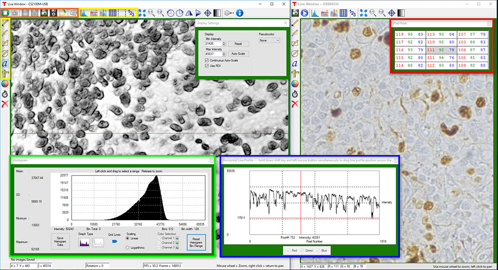
カメラ制御およびイメージ取得
カメラ制御およびイメージ取得機能は、ウィンドウの上にあるアイコン(上の画像中のオレンジの枠内)から実行できます。カメラパラメータの設定は、ツールアイコンをクリックすると表示されるポップアップウィンドウ内で行えます。スナップショットボタンを押すと、現在のカメラ設定を使用したシングルイメージが取得できます。
キャプチャスタート/ストップボタンを押すと、トリガイメージなどのカメラ設定に基づいたイメージキャプチャを開始します。
時系列および像系列のレビュー
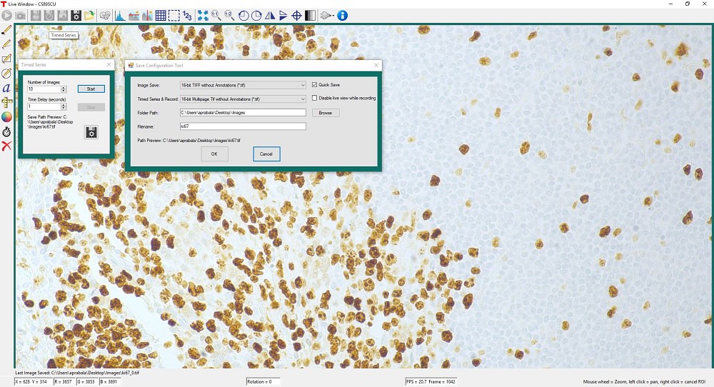
図1のような時系列制御により、低速度画像の記録ができます。画像の総数とキャプチャ間の遅延時間を設定してください。出力結果は、高精度の無修正画像データとして保存するために、マルチページTIFFファイルとして保存されます。ThorCam内で、画像のシークエンス再生やフレームごとのコマ送り再生が可能です。
測定および注釈機能
上の画像の黄色い枠内にあるように、ThorCamには注釈および測定機能が多数内蔵されています。これは取得後の画像を分析する際に役立ちます。直線、長方形、円およびフリーハンドによる図形を画像上に描くことができます。注釈マークを付けた位置には文字を入力できます。また、測定モードでは対象とする2点間の距離を計測できます。
上の画像内の赤、緑、青の枠で囲まれた部分に、ライブ画像および取得済み画像に関する情報を表示させることができます。
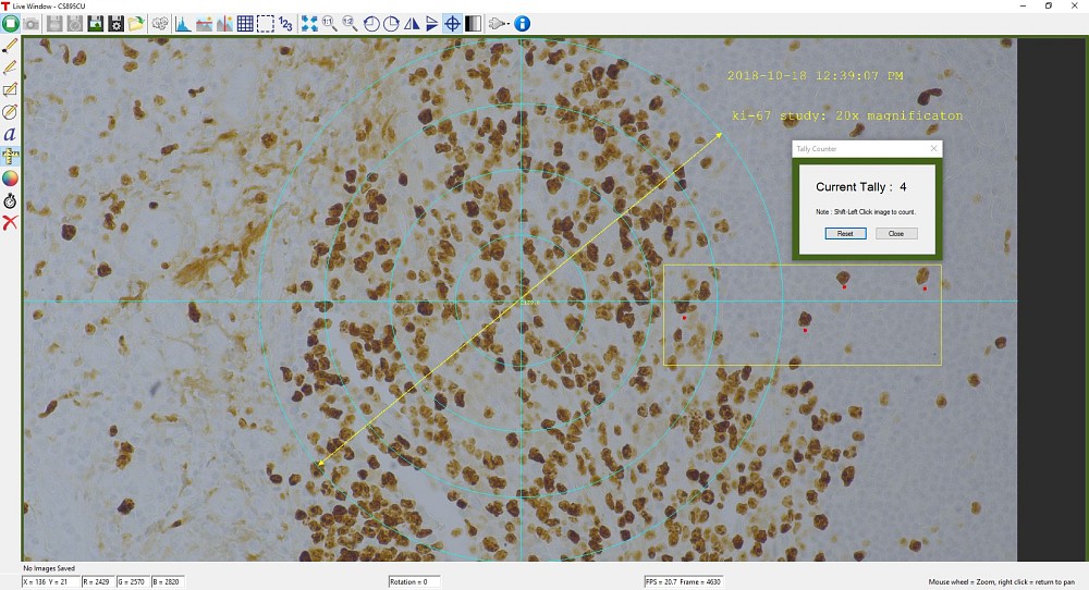
ThorCamには計数機能も内蔵されており、画像内の対象点に印をつけてその数を計数することができます(図2参照)。画像の中心に固定されている十字のターゲットが基準点となります。
サードパーティアプリケーションおよびサポート
ThorCamは、LabVIEW、MATLAB、.NET.などのサードパーティソフトウェアパッケージもサポートしています。LabVIEWとMATLABは32ビット版ならびに64ビット版の両方をサポートいたします。当社カメラに付属する解説付きのフル機能APIを使えば、カメラを効率的にフルカスタマイズできます。
Click to Enlarge
図1:1秒間隔で撮影された10枚の時系列画像が、マルチページTIFFファイルとして保存されます。
Click to Enlarge
図2: ThorCamソフトウェアのスクリーンショット。計数機能によって画像内の3地点がマークされています。測定機能によって左下の直線が付加されています。直線の上には対象点間の距離がピクセル単位で表示されています。
性能に関する注意点
イメージシーケンスをディスクに保存するときに、システム性能が十分でないと「フレーム落ち」が発生する可能性がありますのでご注意ください。ホストシステムがカメラの出力データストリームを処理する能力は、ホストシステムの様々な特性に依存します。なお、USBハブを使用すると性能に影響を与える可能性があります。PCとは専用のケーブルで接続することをお勧めいたします。USB 2.0による接続はサポートされておりません。
まず、カメラのフレームレートと、ホストPCが画像を表示する能力およびフレーム落ちせずにディスクにストリーミングする能力とを区別することが重要です。カメラのフレームレートは露光および読み出し(例えば、クロックやROI)パラメータに依存します。ユーザによって設定された画像取得パラメータに基づいて、カメラのタイミング機能はデジタルカウンタのように動作し、1秒間にある特定の数のフレームを生成します。画像を表示するときは、このデータがPCのグラフィックシステムによって処理され、画像や動画を保存するときにはディスクに転送されます。この時、ハードドライブの速度が十分でないとフレーム落ちが発生します。
この問題に対する解決策の1つとして、ソリッドステートドライブ(SSD)のご使用をお勧めいたします。PCのそれ以外の仕様が十分であれば、多くの場合はこれによって解決します。SSDへの書き込み速度は、データのスループットを処理するのに十分なものでなければなりません。
大きなフォーマットの画像を早いフレームレートで処理する場合には、より速いスピードが必要な場合があります。その場合は、複数のSSDを用いてRAID0を構成するか、あるいはRAMドライブを使うといった方法が考えられます。後者の方法では保存スペースがPC上のRAMで制限されてしまいますが、実現可能な方法としては最も高速なものです。ImDiskは、無料のRAMディスク作製用ソフトウェアパッケージの一例です。RAMドライブは揮発性メモリであることにご注意ください。従って、データの損失を防ぐために、PCを再起動またはシャットダウンする前に、必ずデータをRAMドライブから不揮発性のハードドライブに移動させることが重要です。
カメラのトリガ操作
当社のサイエンティフィックカメラには3種類の外部トリガモード(ストリーミングオーバーラップ、非同期トリガ、バルブ撮影)があります。動作には外部で生成したトリガーパルスが必要です。トリガーモードは利得やオフセットと同様に、読み出し設定(例:ビニング)とは独立に動作します。下の図1~3はこれらのトリガーモードのタイミング図です。アクティブロー外部TTLトリガを想定しています。
Click to Enlarge
図1:ストリーミングオーバーラップ露光モード 外部トリガ信号がローになると、露光が始まり、ソフトウェアで選択した時間の間露光し、読み出されます。このシーケンスは設定された時間間隔で繰り返されます。後続の外部トリガは、カメラ動作が停止するまで無視されます。TTL信号の定義は「ピン配列」タブをご参照ください。
Click to Enlarge
図2:非同期トリガ画像取得モード 外部トリガ信号がローになると、プリセットされた時間の間露光がはじまり、カメラで読み出されます。読み出し時間の間、外部トリガは無視されます。1つの読み出しが終わると、カメラは外部トリガ信号がローになったときのみ次の露光を始めます。
Click to Enlarge
図3:バルブ露光モード 外部トリガ信号がローになると露光が始まり、ハイになると露光が終わります。カメラの読み出し中のトリガ信号は無視されます。
CMOSカメラに特有なタイミングに関する考慮事項
当社のCMOSセンサーカメラの一般的な動作特性とシステム固有の伝搬遅延により、上記のタイミングに関して下記の事項を考慮する必要があります。
- 外部トリガから露光開始およびストローブ信号出力までの遅延時間は、すべてのトリガモード(標準およびPDX/Bulb)において270 ns(典型値)です。
- PDX/Bulbモードによる露光の場合、露光開始の270 nsの遅延時間のほかに、外部トリガの立ち下がりエッジの後に13.72 μsの積分時間が発生します。この時間はこのセンサの動作に固有のものです。Strobe_out信号にはこの13.72 μsの積分時間の効果が含まれているため、Strobe_out信号は実際の露光時間により近い時間を表しています。当社では、露光時間はStrobe_out信号を用いて測定し、PDXモードのトリガーパルスはその結果に基づいて調整することをお勧めします。
外部トリガ
Click to Enlarge
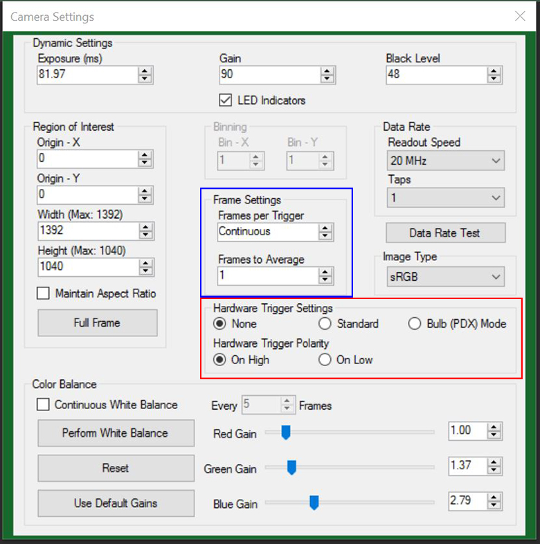
図4:ThorCamカメラの設定画面。赤と青の枠内ではトリガの設定を示しています。
外部トリガ機能により、カメラをほかの外部接続装置と同期させる必要のあるシステムに簡単に組み込むことができます。ストローブ出力がハイの状態は露光していることを示します。従ってストローブ信号は外部機器とカメラの露光を同期させるためのシステムを構成するのに利用できます。外部トリガはカメラの補助ポートへの接続が必要です。当社では補助ケーブル8050-CAB1を別途ご用意しております。個々の信号を分岐する製品は2種類あります。TSI-IOBOBには、各信号用にSMAコネクタが付いています。また、TSI-IOBOB2には、SMAコネクタのほかにArduinoボード用のシールド機能が付いており、その他の周辺機器の制御が可能です。これらのアクセサリの詳細については下記をご覧ください。
トリガの設定はThorCamソフトウェアで調整可能です。図4は、カメラの設定画面です。赤枠と青枠内がトリガの設定画面です。設定は以下の通り調整できます。
- 「Hardware Trigger」(赤枠内)を「None」に設定したとき:ThorCamのキャプチャーボタンを押すと、カメラは単純に「Frames per Trigger」に設定されたフレーム数を取得します。
- 「Hardware Trigger」を「Standard」に設定したとき:2通りのモードがあります。
- 「Frames per Trigger」(青枠内)がゼロ、または>1の場合:カメラはストリーミングオーバーラップ露光モードで動作します(図1参照)。
- 「Frames per Trigger」が1の場合:カメラは非同期トリガ画像取得モードで動作します(図2参照)。
- 「Hardware Trigger」を「Bulb (PDX) Mode」に設定したとき:カメラはバルブ露光モード(「パルス駆動露光(PDX)モード」とも呼ばれる)で動作します(図3参照)。
またトリガの極性は「Hardware Trigger Polarity」 (図4の赤枠内) で「On High」(立ち上がりエッジで露光開始)または「On Low」(立ち下がりエッジで露光開始)に設定することができます。
サイエンティフィックカメラ用アクセサリを使用したカメラのトリガ構成例
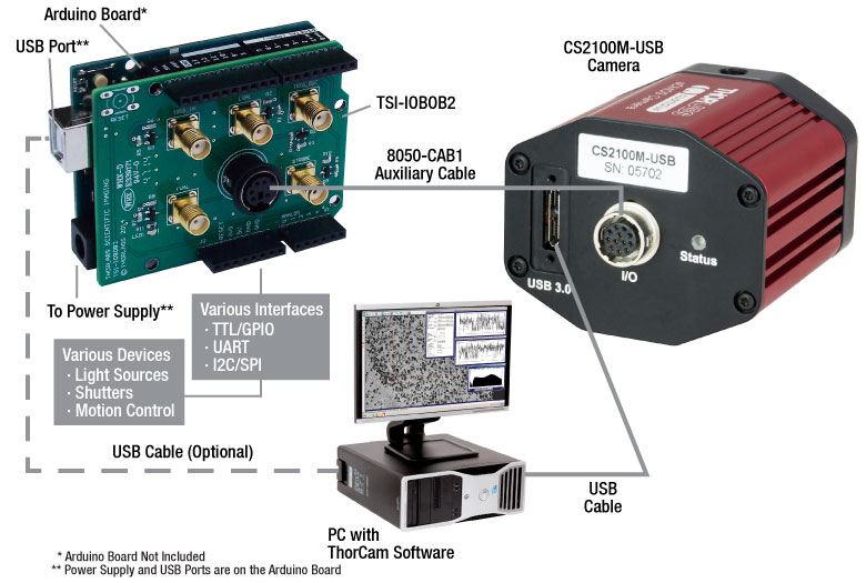
図 5:システムの構築と制御を容易にするTSI-IOBOB2を用いたシステム概略図
図ではQuantalux™ sCMOSカメラの背面パネルが表示されていますが、サイエンティフィックCCDカメラも同様にご使用いただけます。
システム制御にカメラトリガを組み込んだ例が図5で示されています。図では、カメラがArduino用シールド付きブレイクアウトボードTSI-IOBOB2にケーブル8050-CAB1で接続されています。シールドのピンを利用して信号を送ることにより、光源、シャッタならびにモーションコントロールデバイスなどの周辺機器を同時制御することも可能です。制御プログラムをArduinoボードに書き込んだ後、ホストPCからUSB接続を取り外せば、スタンドアローンのシステム制御が可能なプラットフォームとなります。またUSBを接続したままにすればArduinoとPCの双方向通信が可能となります。外部トリガーモードは上記で説明したとおりThorCamを使用して設定します。
カメラのノイズと温度
概要
カメラの購入時に重要となるのは、冷却センサが必要かどうかの判断です。一般的な多くの用途では信号レベルが高いために、冷却は必要ではありません。 しかし低光量の状況下では長い露出時間が必要なため、ほとんどの場合冷却タイプがメリットをもたらします。 下に掲載しているチュートリアルでは以下の経験則を証明しています。1秒未満の露出時間にはほとんどの場合、標準(非冷却)のカメラが適当で、1秒以上の露出時間では冷却タイプが有効です。5秒以上の 露出時間には冷却タイプをお勧めします。また、10秒以上の露出時間では通常冷却タイプが必要となります。 どちらの用途か迷う場合には、下記チュートリアルに記載されている計算式を用いて信号レベルならびにノイズ値をお求めになることをお勧めします。 下記では当社の1.4メガピクセルカメラの仕様を用いた計算例を示しています。ご不明な場合は当社までご相談ください。
ノイズの原因
カメラ画像のノイズの原因は、照明が安定して均一であると仮定すると、測定信号の空間的・時間的バラツキの積み重ねであると言えます。 ノイズには複数の要因があります:
- ダークショットノイズ (σD): 暗電流とは、カメラに全く光子が入射しない状況でも流れている電流です。 熱によって引き起こされる現象で、シリコン製のチップから自然発生的に起こる電子(価電子は熱によって伝導バンドに励起されます)によるものです。 露光中に取得される暗電子の量のバラツキがダークショットノイズです。 表1でみられるように、この数値は信号レベルには依存しませんが、センサ温度には依存します。
- 読取りノイズ(σR): これは電子信号を生成する際に発生するノイズです。センサの設計が引き起こすノイズですが、カメラの電子部品の設計の影響も受けます。このノイズは、信号レベルやセンサ温度には影響を受けず、CCDピクセルクロックレートが高速になると大きくなります。
- フォトンショットノイズ (σS): フォトンショットノイズは、光子がピクセルに達する際に起こる統計的ノイズです。 フォトンの測定はポアソン統計に従うため、フォトンショットノイズは、測定される信号レベルに依存します。 なお、センサ温度には依存しません。
- 固定パターンノイズ (σF): このノイズは、ピクセルの空間的な不均一性が原因で、信号レベルやセンサ温度には無関係です。 なお、固定パターンノイズは、下記の説明においては考慮に入れないこととします。このノイズはここで販売されるCCDカメラにはあまり関係のないノイズですが、サイエンス用よりも低グレードの他のセンサを検討する上では必要となる場合があります。
有効ノイズの総量
1個のピクセルあたりの有効ノイズの総量とは、上記のノイズの求積法による和です。
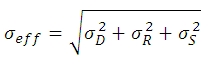
ここでは、σDがダークショットノイズ、 σRが読取りノイズ (CCD ICX285ALを使用しているサイエンス用レベルのカメラでの典型値は10 e-未満ですが、このチュートリアルでは、10 e-であると仮定します)、そしてσS がフォトンショットノイズです。 σS>>≫σD であり、σS>>σRである時、下記の数式で近似的にσeffが求められます:
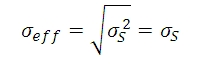
繰り返しますが、ここでは固定パターンノイズは考慮に入れません。そしてこのことはサイエンス用のCCDを考える上では妥当かもしれませんが、サイエンス用よりもグレードの低いセンサでは、考慮に入れなければならない場合もあると考えます。
| Temperature | Dark Current (ID) |
|---|---|
| -20 °C | 0.1 e-/(s•pixel) |
| 0 °C | 1 e-/(s•pixel) |
| 25 °C | 5 e-/(s•pixel) |
Click to Enlarge
図1: 3つのセンサ温度において、露出時間の変化にともなうダークショットノイズと読取りノイズの変化を示したグラフです。 このグラフではxy軸はともに対数目盛です。5 sのところで縦に点線が引かれていますが、これは文章内の数式例での数値です。
ダークショットノイズとセンサ温度
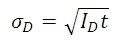
上述のように、暗電流は熱によって生じるため、センサを冷却することで低減できます。表1は、CCDセンサを用いたカメラ(サンプル)の暗電流の典型値を示しています。暗電流は自然発生した電子によって起こるので、単純に電子の数を「数える」ことで測定されます。 電子のカウントはポワソン統計に従うため、暗電流 IDが引き起こすノイズは、露出中に蓄積する暗電子の数の平方根に比例します。 既知の露出において、ダークショットノイズ σDは、表1に記載のある IDの値 (既知の温度に対応した数値) と露出時間t(秒)の積の平方根となります。
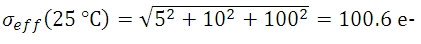
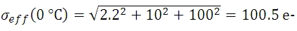
暗電流は、温度の低下に伴って減少するので、これに関連したノイズはカメラの冷却で低減できます。 例えば露出時間が5秒であるとき、表で示される3つのセンサ温度でのダークショットノイズレベルは下記の数式で得られます。
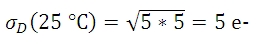
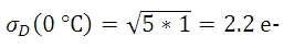
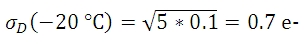
図1はプロット図で、表1の3つの温度における露出時間とダークショットノイズの関係を表し、露出時間が増えるにつれてダークショットノイズが増大することがわかります。 図1には、読取りノイズの上限も示されています。
フォトンショットノイズがダークショットノイズと比較して十分に大きければ、ノイズに対する影響という意味では冷却がもたらすメリットは小さく、そのような条件でもカメラは十分に機能します。
フォトンショットノイズ
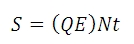
量子効率がQEのセンサの各ピクセルに入射する光量子束密度(フォトン/秒)がNであるとして、露出時間がt秒のときに生成される「信号」の電子の数がSとすると
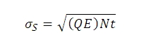
Sから、フォトンショットノイズ σSは下記の数式で求められます:
計算例(当社の1.4メガピクセルカメラを使用)
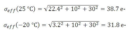
光量子束密度と量子効率が十分に高い値で、露出時間が5秒の時にピクセルに蓄積される信号 S の数が10,000 e-であれば、予測されるショットノイズの値 σSは、10,000の平方根または100 e-となります。 読取りノイズは10 e-です (露出時間に依存しません)。 露出時間が5秒で、センサ温度が25、 0、 -25 °Cであるとき、ダークショットノイズは数式(4)によって得られます。 有効ノイズは下記のとおりです:

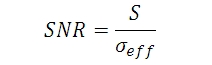
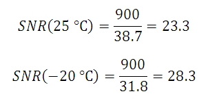
信号対雑音比(SNR)は、画像品質を示す便利な性能指数で、下記の通り見積もられます:
数式7から3つのセンサ温度におけるSNRの値は下記の数式であらわすことができます:
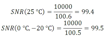
この例でわかるように、室温では非冷却タイプカメラの代わりに冷却型タイプを使うメリットはほとんどなく、この例ではフォトンショットノイズが主なノイズの原因となっています。 このような条件では、当社の標準タイプのパッケージのカメラは十分な性能を発揮することが予測されます。
しかし、光量が低いために1個のピクセルあたり900 e-の数値を達成する上で100秒の露出時間が必要な時には、ショットノイズは30 e-となります。 予測されるダークショットノイズは25 °Cで22.4 e- となり、一方で-20 °C でのダークショットノイズは3.2 e-となります。 有効な総ノイズ量は下記の数式で示すことができます。
数式8からSNR値が下記であることが導出できます。
| Exposure | Camera Recommendation |
|---|---|
| < 1 s | Standard Non-Cooled Camera Generally Sufficient |
| 1 s to 5 s | Cooled Camera Could Be Helpful |
| 5 s to 10 s | Cooled Camera Recommended |
| > 10 s | Cooled Camera Usually Required |
この例では25 °Cのセンサにおけるダークショットノイズの総ノイズ量に対する影響は、-25 °Cのセンサよりも大きくなっています。 用途によって許容されるノイズ量は変化しますが、場合によっては冷却型カメラの方が有効な場合があります。
図2 は、3つの異なるセンサ温度でのダークショットノイズをはじめとした様々なノイズの要素の変化をプロットで表していますが、3種類の光量子束密度において、露出時間を変化させて比較しています。 このプロットを見ると、ダークショットノイズは総ノイズ量に大きく影響していませんが、信号レベルが低いとき(そしてその結果として露出時間が長い場合)は例外です。 図においては、計算で使われれる光量子束密度が示されていますが、各用途において冷却モデルのカメラを使用するか否かの判断では、正確な光量子束密度の値は必要ではありません。 図2をご参照いただければ、露出時間に対する数値的な目安がわかるようになっており、露出時間の予測がつけば冷却モデルのカメラが必要であるかどうかがわかります。その概要は表2にまとめてあります。 ノイズの主な原因が読取りノイズだと判明した場合、読取りノイズを低くするために、より低い20 MHzのCCDピクセルクロック速度でカメラを動作することを推奨します。
図2: 3つの光量子束密度で、露出時間を変化させた場合の総ノイズ量(すべてのノイズ源からの合計)の推移を図示しています。(a) 低い光量子束密度(b)中程度の光量子束密度 (c) 高い光量子束密度 (c)では、露出時間が約20秒を超えると、信号電子とフォトンショットノイズが飽和状態になっています。これは、この露出時間に対応する入射光子レベルに対してピクセルが飽和状態に達するためです。 この計算では、量子効率は60% としています。 なお、これらのプロット図ではxy軸で対数目盛を使っていることにご注意ください。
その他の考慮すべき点
ノイズの総量に対してダークショットノイズが大きく影響を与えない場合でも露出時間が長いときには、熱電対冷却を検討する必要があります。これはホットピクセルの影響を低減する一助となるからです。 ホットピクセルは、露出時間が長いときに、「星」のようなパターンの原因となります。 図3 では、その「星」のようなパターンが示されていますが、ここでは露出時間が10秒のときにTEC冷却素子を用いた場合と用いない場合を比較しています。
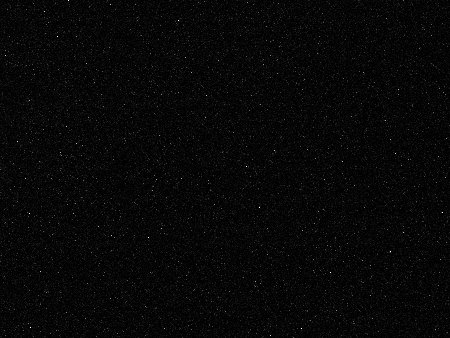
(a)
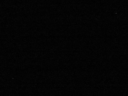
(b)
図3: この画像ではホットピクセルが引き起こした「星」のようなパターンを(a)標準タイプの非冷却モデルのカメラおよび (b) -20 °Cに冷却したカメラで比較しています。いずれも露出時間は10秒で、利得は32 dB です(ホットピクセルがはっきりと見えるように利得を調整しました)。 なお、ここで示されている画像は、フル解像度の16 bit画像から切り取ったものです。 フルサイズの16 bit画像を見るにはこちらからダウンロードしてください。 この画像は無料でダウンロードが可能なImageJなどでご覧いただくことができます。

Insights:当社のサイエンティフィックカメラへのレンズの取付けについて
ここでは、当社のサイエンティフィックカメラを中心に、カメラのマウントとレンズの互換性についてご覧いただけます。
- CマウントとCSマウントのカメラとレンズに互換性はあるか
- 当社のサイエンティフィックカメラにアダプタは必要か
- フランジバックがカメラのフランジとセンサ間の距離よりも短くなり得る理由は
実験および機器についての「Insights-ヒント集」はこちらからご覧いただけます。
CマウントとCSマウントのカメラとレンズに互換性はあるか
Click to Enlarge
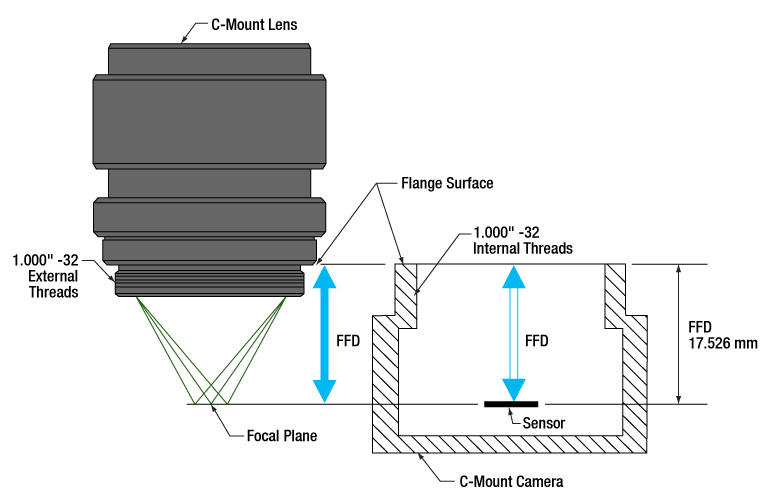
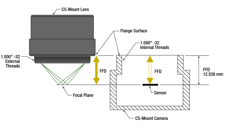
図1: Cマウントのレンズとカメラのフランジバックは同じで、17.526 mmです。そのためレンズを通る光は必ずカメラのセンサ上に焦点を結びます。どちらのコンポーネントにも1.000"-32ネジが付いており、これらは「C-マウントネジ」とも呼ばれます。
Click to Enlarge
図2:CSマウントのレンズとカメラのフランジバックは同じで、12.526 mmです。そのためレンズを通る光は必ずカメラのセンサ上に焦点を結びます。1.000"-32ネジはCマウントのコンポーネントに付いているネジと同じで、これらは「Cマウントネジ」とも呼ばれます。
CマウントとCSマウントのカメラシステムにはどちらも1.000"-32ネジが付いていますが、この2つのマウントのフランジバック(フランジ焦点距離/FFD、フランジ焦点深度、フランジ-フィルム間距離などとも呼ばれる)は異なります。Cマウントのフランジバックは17.526 mm(図1)、CSマウントのフランジバックは12.526 mm(図2)です。
フランジバックが異なるため、CマウントとCSマウントのコンポーネントには互換性がありません。しかしアダプタを用いることによってCマウントレンズをCSマウントカメラに使用することは可能です。
CマウントとCSマウントの組み合わせ
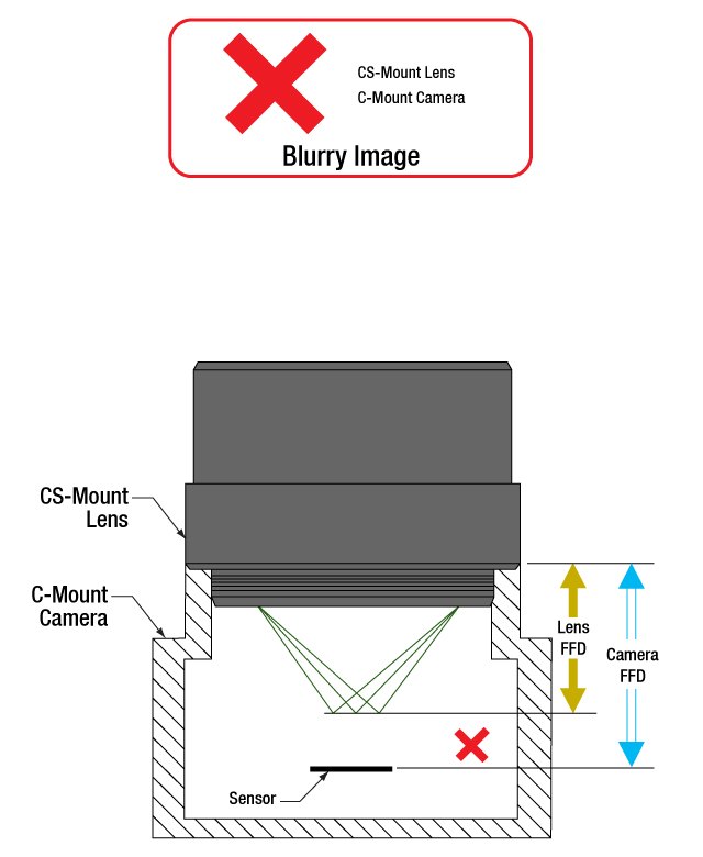
CマウントとCSマウントのネジ規格は同じですが、マウントの種類が異なるレンズとカメラを直接取り付けることはできません。直接取り付けると、フランジバックが異なるためレンズの焦点面がカメラのセンサ面と一致せず、象がぼやけます。
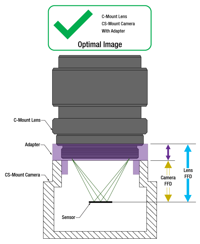
アダプタを使用することで、CマウントレンズをCSマウントカメラに使用することはできます(図3、4)。アダプタによりレンズとカメラのセンサの間隔が5.0 mmだけ長くなり、レンズの焦点面を確実にカメラのセンサ面に一致させることができます。
一方、フランジバックの短いCSマウントレンズは、Cマウントカメラには使用できません(図5)。レンズとカメラの筐体が干渉してカメラのセンサに焦点が合う位置までレンズを近づけることができず、またレンズを近づけられるようなアダプタはありません。
レンズとカメラのパラメータを確認し、互換性のあるコンポーネントなのかどうか、アダプタが必要かどうか、また互換性を持たせる手段はないかを判断することが重要です。
1.000"-32ネジ
インチ規格のネジは、その径とTPI(1インチあたりのネジ山数)によって正確に表現されています。これらの両方のマウントのネジ径は1.000インチ、TPIは32です。Cマウント製品の普及により、1.000"-32ネジは「Cマウントネジ」と呼ばれることがあります。しかし、CSマウントデバイスにも同じネジが用いられているため、この用語は混乱を招く場合があります。
フランジバックについて
フランジバックの値はレンズとカメラの両方について与えられます(図1、2)。レンズの場合、フランジバックはレンズのフランジ面から焦点面までの距離です。フランジ面はレンズ後方のフラットな面で、1.000"-32外ネジとその起点で交差しています。カメラの場合、フランジバックはカメラの前面からセンサ面までの距離です。 レンズがアダプタ無しでカメラに取り付けられているとき、カメラ前方のフランジ面とレンズ後方の面は接触しています。
Click to Enlarge
図5:CSマウントレンズをCマウントカメラに直接取り付けると、光はカメラのセンサの手前で焦点を結びます。この場合はフランジバックを青色の矢印の距離だけ短くする必要がありますが、これはアダプタなどでは対処できません。
Click to Enlarge
図4: 紫色の矢印が示す距離に相当する適切な厚さのアダプタを使用すると、Cマウントレンズの位置はCSマウントカメラのセンサから最適な位置に配置されます。これによりフランジバックが異なっても、光はカメラのセンサ上に焦点を結ぶことができます。

Click to Enlarge
図3:マウントレンズとCSマウントカメラは、レンズのフランジバック(青色の矢印)とカメラのフランジバック(黄色の矢印)が異なるため、直接取り付けることはできません。光はカメラのセンサ上に焦点を結ばす、像がぼやけます。
最終更新日:2020年7月21日
当社のサイエンティフィックカメラにアダプタは必要か
Click to Enlarge
図6:アダプタを使用することで、フランジバックが17.526 mmよりも短いカメラに対して、Cマウントレンズを適切な位置に配置することができます。この図は、ZeluxカメラとアダプタSM1A10Zをもとに描かれています。
Click to Enlarge
図7: アダプタを使用することで、フランジバックが12.526 mmよりも短いカメラに対して、CSマウントレンズを適切な位置に配置することができます。この図は、ZeluxカメラとアダプタSM1A10をもとに描かれています。
当社のサイエンティフィックカメラKiralux™およびQuantalux®は、すべてCマウントレンズに対応するように予め設定されています。これらのパッシブ冷却方式のカメラからCマウントアダプタを取り外すと、フランジ内のSM1内ネジがご利用いただけます。サイエンティフィックカメラZeluxの取付けフランジにもSM1内ネジが付いています。またCマウントアダプタやCSマウントアダプタもご利用いただけます。
カメラ筐体にはSM1ネジが付いており、これによって当社のコンポーネントで構成されたレンズアセンブリを容易に使用することができます。アダプタを使用すれば、カメラのCマウント構成を変えることも可能です。用途に特化したレンズアセンブリを設計する場合や、そのカメラ用に設計されたものではないアダプタを使用しようとする場合には、カメラとレンズのフランジバック(FFD)が一致し、またカメラセンサのサイズが視野に適していることを確認することが重要です。
カメラとそのアダプタ
ZeluxカメラをCマウントやCSマウント規格に適合する構成に変換するための固定式アダプタをご用意しております(図6、7)。これらのアダプタは、パッシブ冷却方式のKiraluxおよびQuantaluxカメラに付属する調整機能付きCマウントアダプタと同様に、それぞれのカメラ専用に設計されています。
SM1ネジを1.000"-32ネジに変換するアダプタであれば、どの様なものでもカメラにCマウントやCSマウントのレンズを取り付けることが可能ですが、すべてのネジアダプタがレンズの焦点面を特定のカメラのセンサ面に一致させることができるわけではありません。場合によっては、それらの面を一致させられるアダプタが無いことがあります。例えば、こちらのサイエンティフィックカメラでは、ZeluxカメラだけがCSマウントレンズ用の構成にすることができます。
レンズの焦点面の位置は、空気中で測定されるレンズのフランジバックと、レンズとカメラセンサ間に置かれた屈折率を有する全ての光学素子との組み合わせで決定されます。レンズによって集光される光が屈折率を有する光学素子を透過すると、空気中を伝搬する場合とは異なり、焦点面はより遠い位置に移動します(この距離は算出可能)。 このアダプタは、カメラのフランジバックが短いときに、そのフランジバックの長さと、レンズとセンサ間のウィンドウやフィルタによって生じる焦点移動の両方を補正するのに十分な距離を付加するものでなければなりません。
調整機能付きCマウントアダプタ
パッシブ冷却方式のカメラKiraluxおよびQuantaluxは、SM1内ネジ付きカメラ、固定リングで固定されたウィンドウまたはフィルタ(センサの覆い)、および調整機能付きCマウントアダプタから構成されています。
調整機能付きCマウントアダプタの利点は、ウィンドウまたはフィルタと固定リングが取り付けられている時に、レンズとカメラ間の距離を1.8 mmの範囲で調整できることです。調整可能なことで、カメラのセンサ面とレンズの焦点面のミスアライメントによる様々な影響を補正することができます。それらの影響には、温度変化による材料の膨張や収縮、累積公差による位置誤差、異なる厚さや屈折率のウィンドウまたはフィルタに交換したことに伴う焦点シフトなどが含まれます。
無限遠にある物体の鮮明な像を得るためには、カメラのアダプタの調整が必要な場合があります。物体が無限遠にある場合には入射光は平行光であり、レンズのフランジバックは焦点の位置で決定されます。レンズやカメラの実際のフランジバックが意図したフランジバックと一致していない場合があり、無限遠の物体が焦点を結ぶ面がセンサ面からシフトし、そのため像がぼやけてしまうことがあります。
レンズの焦点調整をしても無限遠の物体の鮮明な像が得られない場合には、カメラのアダプタで調整してみてください。アダプタで調整することで公差や環境によるシフトが補正され、像の焦点を合わせることができます。
最終更新日:2020年8月2日
フランジバックがカメラのフランジとセンサ間の距離よりも短くなり得る理由は
Click to Enlarge
図9:屈折率の違い(θm vs. θo )により光線が屈折するため、光線の光軸に対する角度は空気中よりも媒質内で浅くなります(nm vs. no )。媒質内でdの距離を伝搬したとき、光線は hm しか光軸に近くなりません。そのため、光線はfの位置よりもΔfだけ遠い位置で光軸と交差します。
Click to Enlarge
図8:空気中を通る光線は、f.位置で光軸と交差します。光線は距離dを伝搬すると、hoだけ光軸に近くなります。空気の屈折率はno です。
| Example of Calculating Focal Shift | |||
|---|---|---|---|
| Known Information | |||
| C-Mount FFD | f | 17.526 mm | |
| Total Glass Thickness | d | ~1.6 mm | |
| Refractive Index of Air | no | 1 | |
| Refractive Index of Glass | nm | 1.5 | |
| Lens f-Number | f / N | f / 1.4 | |
| Parameter to Calculate | Exact Equations | Paraxial Approximation | |
| θo | 20° | ||
| ho | 0.57 mm | --- | |
| θm | 13° | --- | |
| hm | 0.37 mm | --- | |
| Δf | 0.57 mm | 0.53 mm | |
| f + Δf | 18.1 mm | 18.1 mm | |
| Equations for Calculating the Focal Shift (Δf ) | ||
|---|---|---|
| Angle of Ray in Air, from Lens f-Number ( f / N ) |  | |
| Change in Distance to Axis, Travelling through Air (Figure 8) |  | |
| Angle of Ray to Axis, in the Medium (Figure 9) | 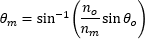 | |
| Change in Distance to Axis, Travelling through Optic (Figure 9) |  | |
| Focal Shift Caused by Refraction through Medium (Figure 9) | Exact Calculation |  |
| Paraxial Approximation |  | |
Click to Enlarge
図11:公差や温度の影響により、レンズとカメラのフランジバックが異なることがあります。レンズのフランジバックの方が短い場合には、無限遠の物体の像は焦点調整範囲外になります。このシステムでは焦点を合わせられないため、像はぼやけます。
Click to Enlarge
図10:カメラとレンズのフランジバックが同じときは、カメラのセンサ面とレンズの焦点面は完全に一致しています。無限遠の物体の鮮明な像は、システムの焦点調整範囲の一端で得られます。
カメラとレンズのフランジバック(FFD)を決めるときは、レンズとカメラのセンサ面の間にあるのは空気のみであることを仮定しています。レンズとカメラのセンサの間にウィンドウまたはフィルタ、あるいはその両方が挿入されている場合は、カメラのフランジとセンサ面の間の距離を仕様で指定されたフランジバックよりも長くする必要があるかもしれません。ウィンドウやフィルタにより光路が屈折して焦点面がより遠い位置にシフトするため、フランジバックと同じ距離では短すぎる場合があります。
レンズとカメラセンサの間の光学素子を変更するなら、焦点面のシフト量を計算し、アライメントを保つためにレンズとカメラ間の距離を調整する必要があるかどうか判断してください。焦点の合った像を得るには、適切なアライメントは必要です。理由は、光学素子を変更することで収差やその他の影響が現れ、画像品質が許容できないレベルに低下することがあるためです。
屈折による焦点移動
光が固体媒質を通るときの光路は直線です(図8)。光が焦点に集光していく過程で、光線の光軸に対する角度
平行平面を有する屈折率の高い
光学素子を通るときの光線は、同じ距離だけ空気を通る光線に比べて、光軸に向かう速さは遅くなります。光学素子から出た後の光線の光軸に対する角度は、また光学素子を通過していないときの角度θoになります。しかし、光学素子から出る光線の位置は、光学素子を通らない場合には決して通ることのない、光軸からより遠く離れた位置になります。光学素子によって屈折された光線は光軸からより遠くなるため、光軸と交差する位置は光学素子を通らない光線よりもΔfだけ先にシフトします。光学素子の厚さが増すと、2つの光線の間は広がり、Δfは増大します。
無限遠およびそれを超えた調整
カメラシステムでは、多くのアプリケーションにおいて、無限遠の物体の高品質な像を得ることが要求されます。これらの物体からの光線は平行光で、近い物体からの光線よりもよりレンズに近い位置で焦点を結びます(図10)。カメラとレンズのフランジバックは、無限遠の位置にある物体からの光線の焦点が、カメラのセンサ面と一致するように決められています。レンズに焦点の調整範囲があるときには、その範囲の一端は無限遠の物体に、もう一端はそれよりも近い物体に焦点が合うように調整されています。
温度変化や累積公差などの影響により、レンズやカメラのフランジバックが仕様を満たさない場合があります。レンズの実際のフランジバックがカメラのフランジバックよりも短いときには、カメラのシステムは無限遠の物体の鮮明な像を得ることはできません(図11)。このオフセットは、レンズとカメラセンサの間にある光学素子を取り外したときも生じることがあります。
これを補正するために、レンズによっては焦点を結ぶ物体の位置を、無限遠を「超えて」設定できるようにしています。これは物理的な距離を意味しているわけではなく、単にレンズの焦点面をより遠くまで移動できるようにしているだけです。当社のKiralux™とQuantalux®カメラに付属する調整機能付きCマウントアダプタは、必要に応じて距離を調整できるようになっています。
レンズのフランジバックがカメラのフランジバックよりも長い場合には、無限遠の物体の像はシステムの焦点調整範囲内にありますが、本来は焦点調整範囲内にあるべき近い物体がその範囲外になります。この状況は、レンズとカメラセンサの間に光学素子を挿入することで生じる場合があります。無限遠の物体のイメージングが可能であるならば、この状況はしばしば許容されることがあります。
カメラの設計例
ハーメチックシールされたTE冷却型のCマウントQuantaluxカメラには、フランジ面とセンサ面の間に18.1 mmの固定された距離があります。しかし、Cマウントカメラシステムのフランジバック(f )は17.526 mmです。フランジバックよりも長い距離が必要であることは、ハーメチックカバーにはんだ付けされているウィンドウとセンサを覆うガラスによる焦点移動を考慮すると明白です。図9の下の表に記載されている結果は、厳密な式でも近軸近似の式でも、必要な全体の距離として18.1 mmという値が得られることを示しています。
最終更新日:2020年7月31日

当社では Zelux®、Kiralux®、Quantalux®の3つのシリーズのサイエンティフィックカメラをご提供しております。Zeluxカメラは汎用的なイメージング向けで、設置面積が小さいながら高いイメージング性能を発揮します。Kiraluxカメラに搭載されているCMOSセンサには、モノクロ、カラー、近赤外(NIR)強化型、偏光検出型などの種類がございます。それらを収めた筐体には、薄型のパッシブ放熱型、小型のパッシブ放熱型、ハーメチックシールされた熱電(TE)冷却型がございます。 偏光検出型Kiraluxカメラにはマイクロ偏光子アレイが組み込まれており、ThorCam™ソフトウェアパッケージを使用すると、直線偏光度、方位角、およびピクセルレベルでの強度を表す画像を取得することができます。QuantaluxモノクロsCMOSカメラは、低光量でも使用できるように広いダイナミックレンジと低い読み出しノイズという特徴を備えています。パッシブ冷却方式のコンパクトな筐体、またはハーメチックシールされたTE冷却素子付き筐体でご用意しています。下の表では当社のカメラのラインナップの概要がご覧いただけます。
| Compact Scientific Cameras | |||||||
|---|---|---|---|---|---|---|---|
| Camera Type | Zelux® CMOS | Kiralux® CMOS | Quantalux® sCMOS | ||||
| 1.6 MP | 1.3 MP | 2.3 MP | 5 MP | 8.9 MP | 12.3 MP | 2.1 MP | |
| Item # | Monochrome: CS165MUa Color: CS165CUa | Mono.: CS135MU Color: CS135CU NIR-Enhanced Mono.: CS135MUN | Mono.: CS235MU Color: CS235CU | Mono., Passive Cooling: CS505MU1 CS505MU Mono., Active Cooling: CC505MU Color: CS505CU1 CS505CU Polarization: CS505MUP1 | Mono., Passive Cooling: CS895MU Mono., Active Cooling: CC895MU Color: CS895CU | Mono., Passive Cooling: CS126MU LP126MU(/M) Mono., Active Cooling: CC126MU Color, Passive Cooling: CS126CU LP126CU(/M) | Monochrome, Passive Cooling: CS2100M-USB Active Cooling: CC215MU |
| Product Photos (Click to Enlarge) |  |  |  | ||||
| Electronic Shutter | Global Shutter | Global Shutter | Rolling Shutterb | ||||
| Sensor Type | CMOS | CMOS | sCMOS | ||||
| Number of Pixels | 1440 x 1080 (H x V) | 1280 x 1024 (H x V) | 1920 x 1200 (H x V) | 2448 x 2048 (H x V) | 4096 x 2160 (H x V) | 4096 x 3000 (H x V) | 1920 x 1080 (H x V) |
| Pixel Size | 3.45 µm x 3.45 µm | 4.8 µm x 4.8 µm | 5.86 µm x 5.86 µm | 3.45 µm x 3.45 µm | 5.04 µm x 5.04 µm | ||
| Optical Format | 1/2.9" (6.2 mm Diag.) | 1/2" (7.76 mm Diag.) | 1/1.2" (13.4 mm Diag.) | 2/3" (11 mm Diag.) | 1" (16 mm Diag.) | 1.1" (17.5 mm Diag.) | 2/3" (11 mm Diag.) |
| Peak Quantum Efficiency (Click for Plot) | Monochrome: 69% at 575 nm Color: Click for Plot | Monochrome: 59% at 550 nm Color: Click for Plot NIR: 60% at 600 nm | Monochrome: 78% at 500 nm Color: Click for Plot | Monochrome & Polarization: 72% (525 to 580 nm) Color: Click for Plot | Monochrome: 72% (525 to 580 nm) Color: Click for Plot | Monochrome: 72% (525 to 580 nm) Color: Click for Plot | Monochrome: 61% (at 600 nm) |
| Max Frame Rate (Full Sensor) | 34.8 fps | 165.5 fps | 39.7 fps | 35 fps (CS505xx1, CC505MU, CS505MUP1), 53.2 fps (CS505xx) | 20.8 fps (CC895MU), 30.15 fps (CS895xx) | 15.1 fps (CC126MU), 21.7 fps (CS126xx and LP126xx(/M)) | 50 fps |
| Read Noise | <4.0 e="" sup="">- RMS | <7.0 e="" sup="">- RMS | <7.0 e="" sup="">- RMS | <2.5 e="" sup="">- RMS | <1 e="" sup="">- Median RMS; <1.5 e="" sup="">- RMS | ||
| Digital Output | 10 Bit (Max) | 10 Bit (Max) | 12 Bit (Max) | 16 Bit (Max) | |||
| PC Interface | USB 3.0 | ||||||
| Available Fanless Cooling | N/A | N/A | N/A | 15 °C to 20 °C Below Ambient Temperature (CCxxxMU Cameras Only) | |||
| Housing Size (Click for Details) | 0.59" x 1.72" x 1.86" (15.0 x 43.7 x 47.2 mm3) | Passively Cooled CMOS Camera TE-Cooled CMOS Camera Passively Cooled Low-Profile CMOS Camera | Passively Cooled sCMOS Camera TE-Cooled sCMOS Camera | ||||
| Typical Applications | Mono. & Color: Brightfield Microscopy, General Purpose Imaging, Machine Vision, Material Sciences, Materials Inspection, Monitoring, Transmitted Light Spectroscopy, UAV, Drone, & Handheld Imaging Mono. Only: Multispectral Imaging, Semiconductor Inspection Color Only: Histopathology | Mono., Color, & NIR: Brightfield Microscopy, Ca++ Ion Imaging, Electrophysiology/Brain Slice Imaging, Flow Cytometry, Fluorescence Microscopy, General Purpose Imaging, Immunohistochemistry (IHC), Laser Speckle Imaging, Machine Vision, Material Sciences, Materials Inspection, Vascular Imaging, Monitoring, Particle Tracking, Transmitted Light Spectroscopy, Vascular Imaging, VIS/NIR Imaging Mono. Only: Multispectral Imaging Semiconductor Inspection Color Only: Histopathology NIR Only: Ophthalmology/Retinal Imaging | Mono. & Color: Autofluorescence, Brightfield Microscopy, Electrophysiology/Brain Slice Imaging, Fluorescence Microscopy, Immunohistochemistry (IHC), Machine Vision, Material Sciences, Materials Inspection, Monitoring, Quantitative Phase-Contrast Microscopy, Transmitted Light Microscopy Mono. Only: Multispectral Imaging Semiconductor Inspection Color Only: Histopathology | Mono. & Color: Autofluorescence, Brightfield Microscopy, Electrophysiology/Brain Slice Imaging, Fluorescence Microscopy, Immunohistochemistry (IHC), Machine Vision, Material Sciences, Materials Inspection, Monitoring, Quantitative Phase-Contrast Microscopy, Transmitted Light Microscopy Mono. Only: Multispectral Imaging, Semiconductor Inspection Color Only: Histopathology Polarization Only: Inspection, Surface Reflection Reduction, Transparent Material Detection | Mono. & Color: Autofluorescence, Brightfield Microscopy, Electrophysiology/Brain Slice Imaging, Fluorescence Microscopy, Immunohistochemistry (IHC), Machine Vision, Material Science, Materials Inspection, Monitoring, Quantitative Phase-Contrast Microscopy, Transmitted Light Microscopy Mono. Only: Multispectral Imaging, Ophthalmology/Retinal Imaging, Semiconductor Inspection Color Only: Histopathology LP126xx(/M), CS126xx, and CC126MU Only: Whole-Slide Microscopy | Passive & Active Cooling: Autofluorescence, Brightfield Microscopy, Fluorescence Microscopy, Immunohistochemistry (IHC), Material Sciences, Materials Inspection, Monitoring, Quantitative Phase-Contrast Microscopy, Quantum Dots, Semiconductor Inspection, Transmitted Light Microscopy, Whole-Slide Microscopy Active Cooling Only: Electrophysiology/Brain Slice Imaging, Multispectral Imaging | |
| Posted Comments: | |
Gregory Badura
(posted 2024-02-13 12:17:54.183) Does this camera allow for saving of exposure time and gain in the EXIF data? Additionally, can this data be accessed by python and/or labview APIs? cdolbashian
(posted 2024-02-19 09:26:18.0) Thank you for reaching out to us with this inquiry. While these API can set and read the various acquisition settings, they cannot save them to the EXIF data. I have contacted you directly to discuss your application further. cdolbashian
(posted 2024-02-19 09:26:18.0) Thank you for reaching out to us with this inquiry. While these API can set and read the various acquisition settings, they cannot save them to the EXIF data. I have contacted you directly to discuss your application further. Ignacio Moreno
(posted 2023-08-09 08:54:52.473) Hello,
I recently purchased you a polarization camera Kiralux.
We would like to use it in combination with your iquid crystal retarders.
We want to do this in Linux or C++.
Are there Linux libraries or libraries in C++ available for the camera and your controllers?
Thanks in advance cdolbashian
(posted 2023-08-16 09:28:18.0) Thank you for reaching out to us with this inquiry. When you download our free "ThorCam" software, you also gain the SDK for this product, which includes support for Python, Labview, C and C++. Additionally, we frequently update our GitHub (Github.com/Thorlabs), with example code for these cameras in various languages. I have reached out to you directly to share such information with you. user
(posted 2022-10-26 09:47:08.253) We ordered a polarization camera before: CS505MUP1. The frame rate (35Hz) of it is bottleneck for high-speed imaging. We really need a high frame rate camera (2kHz), is there possible to custom-made it on thorlabs? cdolbashian
(posted 2022-10-31 01:15:32.0) Thank you for reaching out to us with this inquiry. Unfortunately even when configured for fastest readout speed (only a fraction of the CMOS sensor set to be active), our fastest camera can only reach a fraction of this speed. With out current capabilities, we would not be able to do this, even as a custom. prathmesh ghag
(posted 2022-09-28 20:56:36.12) Dear Sir/Maam,
I have purchased CS505MUP1.
There is provision given for mounting it with 4 screws. The threads are marked as "4-40 TAPPED FOR ER CAGE RODS".
Kindly help me understand this nomenclature.
I need to buy compatible screws for the same.
Thanking you.
regards,
Prathmesh Ghag cdolbashian
(posted 2022-10-04 03:44:47.0) Thank you for reaching out to us with this inquiry. Cage systems are a common optical construction method which we employ. Each cage rod has a small 4-40 screw on the end of each rod, which is likely what you are referring to. I have contacted you directly to discuss mounting options for this camera. Jae-Hwang Lee
(posted 2022-04-05 16:03:30.957) I tried to use the polarization camera via LabView. When using the provided TLCameraSamples.lvproj, I had the following error:
Error 1386 occurred at Invoke Node in Open TLCameraSDK.vi->Image acquisition polarization camera - polling.vi
I am using LabView 2015. Please let me know any possible reasons and solutions.
Thank you! jdelia
(posted 2022-04-22 08:04:37.0) Thank you for contacting Thorlabs. This error will typically mean that the user did not copy the DLL's to the project Library folder, or the project is in a location that the VI account does not have permission to read/modify. It is recommended to copy the Labview project to a folder like the documents, copy the DLL's, and then open/save each VI so the paths are reassociated. I have contacted you directly to discuss your issue further. user
(posted 2022-01-12 05:33:37.75) Hello, could you please add some details on the observation of stress within the glass using this camera?
Thank you Ludo
(posted 2021-05-04 10:55:27.497) I don't see any mention of the actual sensor part number used in your CS505MUP but the specs looks like the IMX250MZR/MYR. Is it or do you use a proprietary sensor? Also, can this camera be operated from a Linux OS? YLohia
(posted 2021-05-10 08:09:41.0) Thank you for contacting Thorlabs. This is indeed the IMX250MZR. Unfortunately, we do not provide Linux drivers for the Kiralux cameras. Juan Campos
(posted 2021-02-07 11:56:30.433) I see that you have the
Polarization Camera with 5.0 MP Monochrome CMOS Sensor
do you plan to include in your catalog the color sensor? YLohia
(posted 2021-02-08 03:56:18.0) Hello, thank you for contacting Thorlabs. Unfortunately, we currently do not have any plans of offering a color version of this. user
(posted 2020-03-31 07:49:16.56) Hi are you planning to release NIR-Enhanced Polarization Camera? YLohia
(posted 2020-03-31 10:28:09.0) Thank you for contacting Thorlabs. While we currently do not have any plans of releasing an NIR-enhanced version of the CS505MUP, we did just release the CS135MUN, which is an NIR-Enhanced CMOS Camera. Yaonan Hou
(posted 2020-02-18 08:18:11.753) Hello,
I bought this polarization camera for use. Can you arrange a technical support to contact me. I need some help in extracting data from the the images (e.g. the image i got from Azimuth is not angles but intensities.).
Thanks.
Best regards,
Yaonan llamb
(posted 2020-02-20 11:24:04.0) Hello Yaonan, thank you for contacting Thorlabs. For future reference, you can reach out directly to your local Thorlabs Tech Support team for direct assistance: +44 (0) 1353-654635 or techsupport.uk@thorlabs.com for you in particular. A representative will reach out to you soon to help. For extracting image data for these cameras in general, there is more information in section 4.3.2 of the User Manual discussing the expressed polarization values. |
Camera Selection Tool
Reset Parametersof 31 Products Shown
Select Parameters
Select Applications
of 31 Products Shown
| Item Number | Sensor Type | Optical Format | Electronic Shutter | Pixel Size | Max Frame Rate | Read Noise | Digital Output | Cooling | Housing Dimensions |
|---|

 ズーム
ズーム
Click for Details
Arduinoに接続されたTSI-IOBOB2から小型サイエンティフィックカメラにトリガ信号を送信するときの概要図
下記のアクセサリを用いると、sCMOSとCMOSカメラの補助ポートを簡単に利用できるようになります。カメラに外部トリガ信号を入力するときや、カメラの状態をオシロスコープでモニタするとき、またはカメラを他の機器と同時に制御する必要があるときなどにご利用ください。
USB3.0カメラ用には、PCに接続する際のPCIe USB3.0カードもご用意しております。
補助I/Oケーブル(8050-CAB1)
8050-CAB1は長さ3 mのケーブルです。当社のサイエンティフィックカメラ*の補助コネクタに接続することで、カメラへの外部トリガ信号の入力やステータス出力信号のモニタができます。ケーブルの一端にはカメラ接続用の12ピンコネクタ(オス)が付いており、もう一端には外部機器接続用の6ピンMini Dinコネクタ(オス)が付いています。このケーブルは、下記のブレイクアウトボードと組み合わせて使用するのに適しています。ピン配列については、「ピン配列」タブをご覧ください。
*8050-CAB1は、当社の旧製品1500Mシリーズカメラには対応しません。
ブレイクアウトボード(TSI-IOBOB)
TSI-IOBOBは、当社のサイエンティフィックカメラの補助ポートに接続されたケーブルの6ピンMini Dinコネクタの信号を、5つのSMAコネクタに分岐します。それぞれのSMAコネクタは、SMAケーブルを介して、カメラへのトリガ信号を送信する機器や、カメラの状態をモニタする機器などと接続することができます。ピン配列については、「ピン配列」タブをご覧ください。
ブレイクアウトボード/Arduino用(TSI-IOBOB2)
TSI-IOBOB2は、TSI-IOBOBと同様にカメラ信号を分岐します。それに加えて、Arduino Uno Rev. 3のフォームファクタをサポートするArduinoボードに取り付けると、TSI-IOBOB2はArduinoのシールドとして機能します。カメラの入出力信号は5 V LVTTLですが、TSI-IOBOB2には双方向ロジックレベルコンバータが搭載されているため、5 Vまたは3.3 Vロジックで動作するArduinoボードにも対応しています。サイエンティフィックカメラ制御用のサンプルプログラムがソフトウェアのページからダウンロードいただけます。またマニュアル(下の型番横の赤いアイコンをクリック)にも記載されています。ArduinoやArduinoボードの詳細についてはwww.arduino.ccをご覧ください。
右の構成図では、カメライメージングシステムに組み込まれたTSI-IOBOB2とArduinoボードを示しています。カメラとブレイクアウトボードはケーブル8050-CAB1(別売り)で接続されています。シールド上のピンを利用して信号を送信し、光源、シャッタ、モーションコントロールデバイスなどの周辺機器を同時に制御することができます。制御プログラムをArduinoボードに書き込んだ後、ホストPCからUSB接続を取り外せば、スタンドアローンでシステム制御が可能なプラットフォームになります。またUSBを接続したままにすればArduinoとPCの双方向通信が可能です。TSI-IOBOB2は68.6 mm x 53.3 mmと小型であるため、コンパクトなシステムを実現できます。
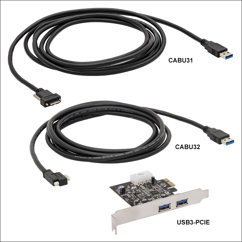
USB 3.0カメラ用アクセサリ(CABU31、CABU32、USB3-PCIE)
当社ではカメラをPCに接続するためのUSB3.0 A-Micro Bケーブルを2種類ご用意しております(各カメラにはストレート型コネクタの付いたケーブルが1本付属しています)。ケーブルCABU31にはストレート型のMicro-Bコネクタが付いており、その両端に付いているネジとデバイス側のタップ穴を結合してコネクタを固定します。ケーブルCABU32にはL型のコネクタが付いており、その固定用ネジは1本になっています。どちらのケーブルも長さは3 mです。
USB 3.0に対応するカメラは、ノート型PCやデスクトップ型PCのUSB 3.0ポートに直接接続できます。USB 3.0カメラはUSB 2.0ポートには適合しません。ホスト側のUSB 3.0ポートは多くの場合は青色ですが、黒色の場合もあります。また、一般にSuperSpeedを表す「SS」マークが付いています。Intel USB 3.0コントローラを内蔵していないPC向けに、USB 3.0用PCIeカードを別売りでご提供しております。なお、USBハブを使用すると性能に影響を与える場合がありますのでご注意ください。PCとは専用ケーブルで接続することをお勧めいたします。

 ズーム
ズーム
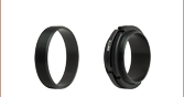
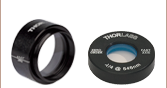
SM1A10Aは、非冷却型Kiralux®およびQuantalux®カメラのための、交換用のSM1-Cマウントアダプタです。アダプタにはSM1外ネジとCマウント内ネジが付いており、多くの顕微鏡、マシンビジョン用カメラレンズ、Cマウントエクステンションチューブに取付け可能です。アダプタにはロッキングリングSM1NTも1個付属します。