 Products Home / 光ファイバーコンポーネント、光ファイバーデバイス / コリメータ/カプラ / 反射型コリメーター / Reflective Collimators, Unprotected Gold Coating
Reflective Collimators, Unprotected Gold Coating
- Unprotected-Gold-Coated Collimators/Couplers with a 7.0 mm Reflected Focal Length
- Maximum Fiber NA of 0.40 without Clipping the Beam
- Free From Chromatic Aberrations
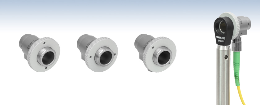
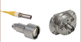
RC02FC-M03
FC/PC Connector
RC02APC-M03
FC/APC Connector
RC02SMA-M03
SMA Connector
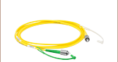
RC02APC-M03
Reflective Collimator
with an FC/APC Patch Cable
Shown Mounted
to an SMR05 Mount on a Ø1/2" Post

Please Wait
Click to Enlarge
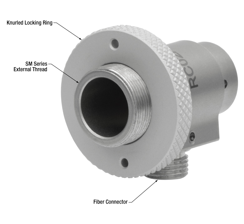
The housings of the RC02 collimators have SM05 (0.535"-40) external threads. A knurled locking ring included with all collimators enables secure mounting of the optic. Please see the Mounting Options tab for details.
Click to Enlarge
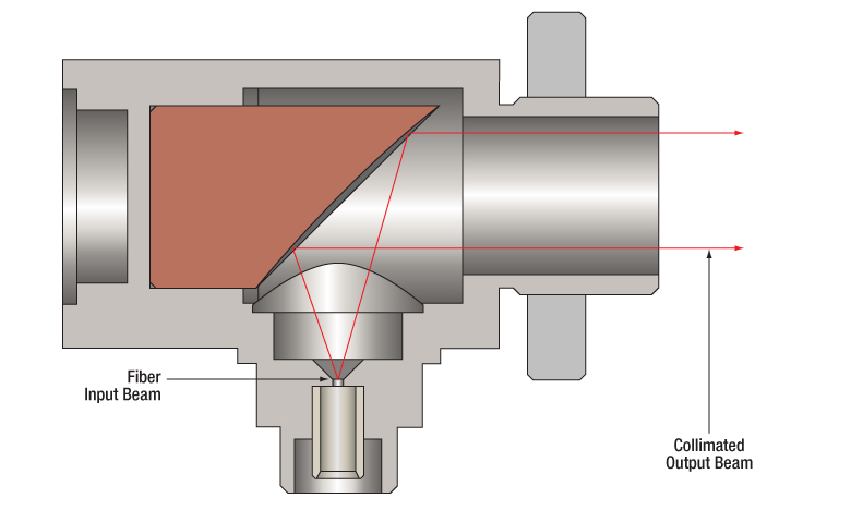
Collimated light from an optical fiber using an RC02-M03 series collimator is shown above. These collimators can also be used in reverse for coupling into a multimode fiber.
Features
- Free from Chromatic Aberrations for Collimation Over the Mirror's Reflection Band
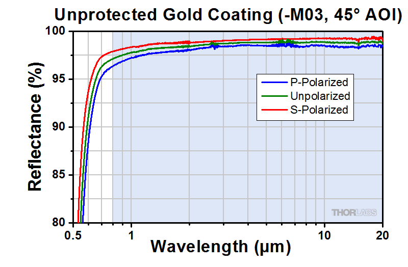
- Unprotected Gold Coating (800 nm - 20 μm) Offers High Reflectance
- Ravg > 97%
- 7.0 mm Reflected Focal Length
- Great for Coupling Polychromatic Light into Multimode Fiber
- FC/PC, FC/APC, or SMA Connector Options Available
- Surface Roughness: <100 Å (RMS)
- Ø7.5 mm Clear Aperture
- Maximum Fiber NA without Clipping the Beam: 0.40
- Non-Magnetic Stainless Steel Housing
Thorlabs' Unprotected Gold Reflective Collimators are based on a 90° off-axis parabolic (OAP) mirror. These unprotected gold mirrors, unlike lenses, have focal lengths that remain constant and offer offer >97% average reflectance within the 800 nm to 20 µm wavelength range (please see the Specs tab for more details). Due to this intrinsic property, parabolic mirror collimators do not need to be adjusted to accommodate various wavelengths of light, making them ideal for use with polychromatic light in the infrared (IR).
Common applications include systems that utilize multiple wavelengths that need to be collimated, collimation/coupling in the IR, and coupling polychromatic light into large-core multimode fiber. When collimating light from a multimode patch cable, the fiber NA should be ≤0.40 to avoid clipping light on the housing. Note too that, in general, light from a multimode fiber cannot be well collimated. For more information on how to optimize coupling of light from an optical fiber, please see the Collimation Tutorial tab.
The reflective collimator housings are equipped with external SM05 (0.535"-40) threads. This makes them directly compatible with our SM05-threaded optomechanics, such as the LMR05(/M) lens mount. The backs of the collimators are machined down to Ø1/2", enabling direct mounting into a Ø1/2" kinematic mount. Furthermore, the housing may be directly mounted to Ø1" kinematic mounts by removing the knurled ring on the front of the housing, holding the housing behind the kinematic mount's Ø1" counterbore, and then rethreading the knurled ring over the back lip of the counterbore and onto the housing using an SPW909 Spanner Wrench or an SPW801 Adjustable Spanner Wrench. The collimator can then be secured by tightening the mount's setscrew. Please see the Mounting Options tab for more details.
Scattering from the mirror surface is minimal (~2% @ 633 nm) due to <100 Å RMS surface roughness achieved by the diamond turning process used to manufacture the off-axis parabolic mirror.
For the 250 - 450 nm, range, Thorlabs offers a line of UV-Enhanced Aluminum Coating Reflective Collimators. For the 450 nm - 20 µm range, Thorlabs also offers several types of collimators with our protected silver coating: Reflective Collimators for large NAs, Adjustable Focus Reflective Collimators, and Compact Collimators for easy integration into a cage system. Like these unprotected gold collimators, both the UV-enhanced aluminum and protected silver reflective collimators are available with a 7.0 mm focal length. Additionally, they are offered with focal lengths of 15.0 mm, 33.0 mm, and 50.8 mm. To order an unprotected gold collimator in one of these focal lengths, please reach out to Tech Sales.
Fiber Patch Cables for Reflective Collimators
Thorlabs offers single mode, polarization-maintaining, or multimode fiber optic patch cables for both coupling and collimating applications. If you cannot find the appropriate stock patch cable for your application, custom patch cables with same-day shipping are also available.
Care and Handling
The unprotected gold layer on these mirrors does not include a protective overcoat. Bare gold does not oxidize in air, but can be easily damaged by fingerprints, aerosols, or the slightest contact with any abrasive material. Unprotected gold mirrors should only be handled when necessary and always held by the sides. Latex gloves or a similar protective covering should be worn to prevent oil from fingers from reaching the surface. No attempt should be made to clean the surface other than blowing off dust with clean, dry air or nitrogen. Any other cleaning method may damage the surface.
| Reflective Collimator Specifications | ||||||||
|---|---|---|---|---|---|---|---|---|
| Item #a | Connector Type |
Max Fiber Numerical Aperture (NA)b | RFLc | External Threading of Housing |
Clear Aperture | Reflectance (Avg., AOI = 45°) | Typical Collimated Beam Diameter (1/e2)d |
Full Angle Beam Divergencee |
| RC02FC-M03 | FC/PC | 0.40 | 7.0 mm | SM05 (0.535"-40) | Ø7.5 mm | >97% (800 nm - 20 µm) |
Ø1.3 mm (SM600 at 633 nm)f Ø1.5 mm (780HP at 780 nm)f Ø1.5 mm (SM980-5.8-125 at 980 nm) Ø1.5 mm (1060XP at 1064 nm) Ø1.3 mm (SMF-28-J9 at 1550 nm) Ø2.2 mm (SM1950 at 2 µm) |
0.035° (SM600 at 633 nm)f 0.037° (780HP at 780 nm)f 0.048° (SM980-5.8-125 at 980 nm) 0.051° (1060XP at 1064 nm) 0.088° (SMF-28-J9 at 1550 nm) 0.067° (SM1950 at 2 µm) |
| RC02APC-M03 | FC/APC | |||||||
| RC02SMA-M03 | SMA | |||||||
| Specifications | |||
|---|---|---|---|
| Item # | RC02FC-M03 | RC02APC-M03 | RC02SMA-M03 |
| Fiber Connector | FC/PC | FC/APC | SMA |
| Pointing Errora | <10 mrad | <10 mrad | - |
| Clear Aperture | Ø7.5 mm | ||
| Typical Collimated Beam Diameter (1/e2)b |
Ø1.3 mm (SM600 at 633 nm)c Ø1.5 mm (780HP at 780 nm)c Ø1.5 mm (SM980-5.8-125 at 980 nm) Ø1.5 mm (1060XP at 1064 nm) Ø1.3 mm (SMF-28-J9 at 1550 nm) Ø2.2 mm (SM1950 at 2 µm) |
||
| Full Angle Beam Divergenced | 0.035° (SM600 at 633 nm)c 0.037° (780HP at 780 nm)c 0.048° (SM980-5.8-125 at 980 nm) 0.051° (1060XP at 1064 nm) 0.088° (SMF-28-J9 at 1550 nm) 0.067° (SM1950 at 2 µm) |
||
| Maximum Fiber Numerical Aperture (NA) |
0.40 | ||
| Reflected Focal Length (RFL) | 7.0 mm at 90° | ||
| Parent Focal Length (PFL)d | 3.5 mm | ||
| Coating | Unprotected Gold | ||
| Wavelength Range | 800 nm - 20 µm | ||
| Reflectance (Avg., AOI = 45°) | >97% | ||
| Surface Quality | 40-20 Scratch-Dig | ||
| Surface Roughness | <100 Å RMS | ||
| Reflected Wavefront Error | λ/4 RMS at 633 nm | ||
Click to Enlarge
The blue shaded region indicates the specified 800 nm - 20 µm
wavelength range for optimum performance. An excel spreadsheet with raw data over the 800 nm - 20 µm range for unprotected gold, 45° AOI is also available.
Thorlabs offers a line of reflective collimators with UV-enhanced aluminum, protected silver, and unprotected gold coatings with focal lengths of 7.0 mm, 15.0 mm, 33.0 mm, or 50.8 mm. Please note that not all of the coatings have stock offerings for all focal lengths. Contact Tech Sales to order a collimator not available in stock. All of our collimators can be mounted in mirror mounts, lens tubes, or integrated into cage systems.
Mirror Mounts
The Ø1", 4.0 mm thick knurled locking ring of the RC02x, RC04x, and RC08x reflective collimators can be used as the mounting surface to secure the collimator into a mirror mount for Ø1" optics, such as the POLARIS-K1E Ø1" side optic retention mount shown in the middle image below. Other mirror mounts or other optic mounts capable of securing a 4.0 mm thick optic can also be used. The RC02x, RC04x, and RC08x collimators feature an SM05 (0.535"-40) external threading which also enables mounting to Thorlabs' SM05-threaded kinematic mirror mounts. The RC12x collimator features an external SM1 (1.035"-40) threading that can be used to mount the collimator to an SM1-threaded kinematic mirror mount or to a mirror mount for Ø2" optics by using an SM1-threaded adapter such as the AD2T adapter. The RC02x collimator can be mounted using the Ø1/2" (12.7 mm) rear surface as shown in the image below.
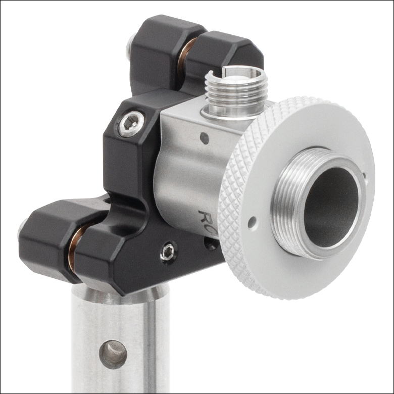
Click to Enlarge An RC02FC-F01 Collimator Secured in a KM05 Kinematic Mirror Mount using the rear mounting surface.
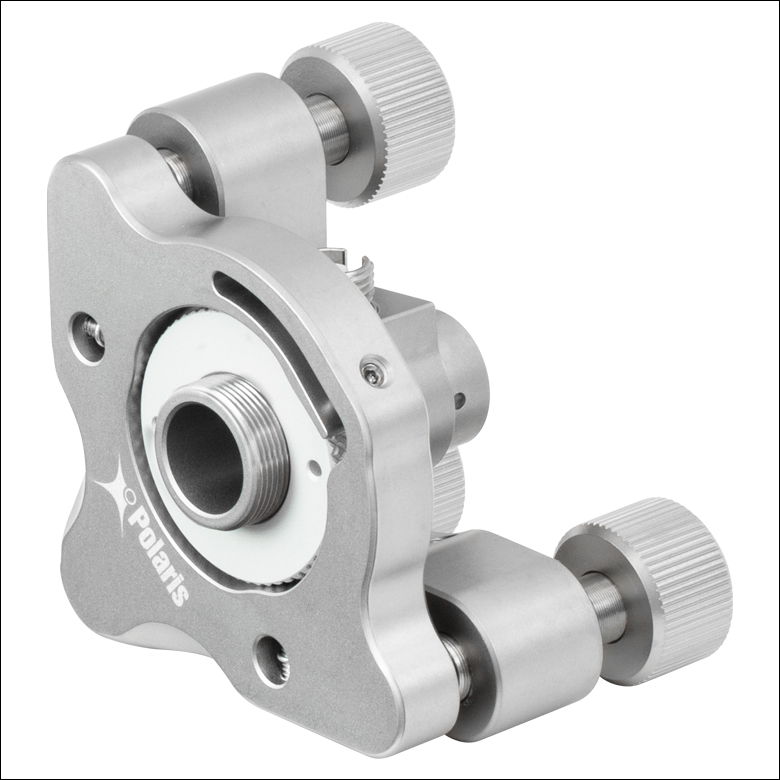
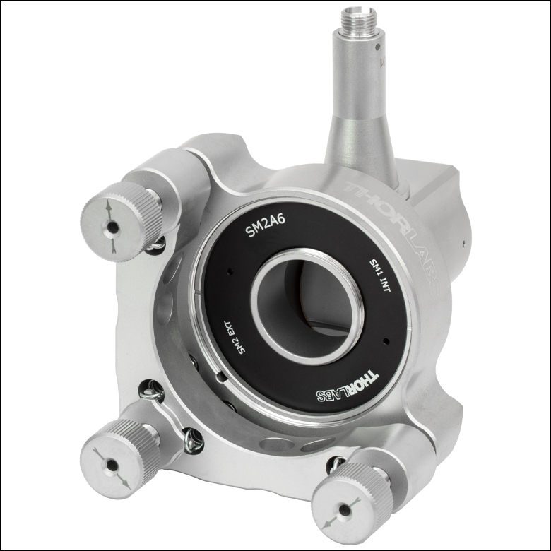
Click to Enlarge An RC12FC-F01 Collimator in a POLARIS-K2T Ø2" Mount using an SM2A6 adapter with SM1-internal and SM2-external threads.
Cage System and Lens Tube Integration
The RC02x, RC04x, and RC08x collimators can be directly integrated into a cage system using the external SM05 (0.535"-40) threading on the collimator housing and an SM05 internally threaded cage component such as Thorlabs' CP32(/M) cage plate for 30 mm cage systems. Similarly, the RC12x collimator can be directly mounted into a cage system using the external SM1 (1.035"-40) threading on the collimator housing and a compatible cage system component such as the CP33(/M) cage plate for 30 mm cage systems.
The SM05 (0.535"-40) or SM1 (1.035"-40) external threading on the RC0x or RC12x collimators, respectively, can also be used to mount a compatible SM-threaded lens tube or other compatible optic for easy system integration.
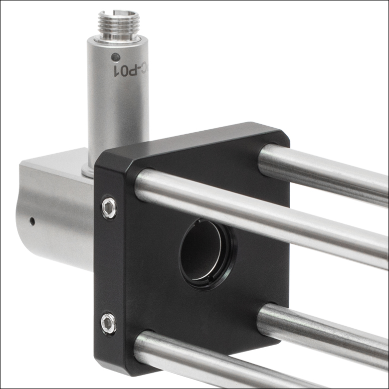
Click to Enlarge An RC08FC-P01 Reflective Collimator is mounted to a CP32 30 mm Cage Plate using the SM05 (0.535"-40) external threads.

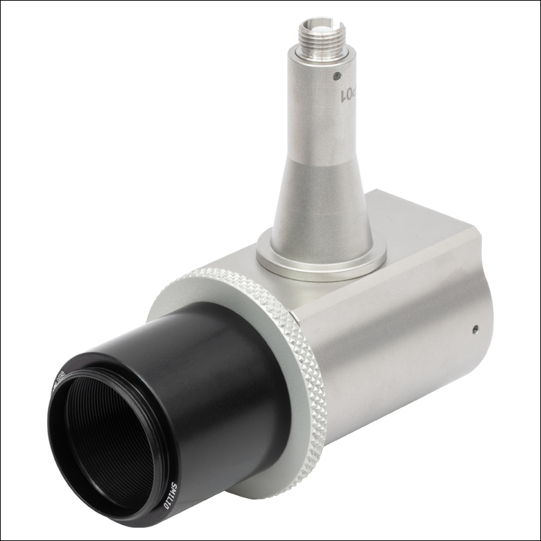
Click to Enlarge An RC08FC-P01 Reflective Collimator with an SM05L10 Lens Tube attached using the SM05 (0.535"-40) external threads.
Click to Enlarge An RC12FC-P01 Reflective Collimator with an SM1L10 Lens Tube attached using the SM1 (1.035"-40) external threads.
Collimating Light Tutorial
Collimating Light from a Single Mode Fiber with a Reflective Collimator
When collimating light from single-mode fibers, the Reflective Fiber Collimators produce beams with large waist diameters and low divergence. The graph below illustrates the theoretical 1/e2 beam diameter as a function of propagation distance for four different SM fiber-coupled laser wavelengths using our reflective collimators. The effect of changing the fiber or the wavelength can be estimated using the theoretical approximations below.
Theoretical Approximation of the Divergence Angle of an Output Beam
The divergence angle can be approximated theoretically using the formula below as long as the light emerging from the fiber has a Gaussian intensity profile. Therefore, the formula works well for single mode (SM) fibers.
The full divergence angle of the output beam using an SM fiber in degrees is approximated by
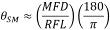
where θSM is the divergence angle of the beam after collimation, MFD is the mode field diameter of the fiber, and RFL is the reflected focal length of the reflective collimator. The MFD and RFL must have the same units in this equation.
Example Calculation:
When the RC02APC-M03 collimator (RFL = 7.0 mm) is used with the P3-980A-FC-1 SM patch cable (MFD = 5.8 µm), the divergence angle is:
θSM ≈ (0.0058 mm / 7.0 mm) x (180 / 3.1416) ≈ 0.047° or 0.83 mrad.
Theoretical Approximation of the Output Beam Diameter
The 1/e2 output beam diameter can be found using the approximation

where λ is the wavelength of light being used, MFD is the mode field diameter of the fiber, and RFL is the reflected focal length of the reflective collimator.
Example Calculation:
When the RC02APC-M03 collimator (RFL = 7.0 mm) is used with the P3-980A-FC-1 SM patch cable (MFD = 5.8 µm) at λ = 980 nm = 0.980 µm, the output beam diameter is:
d = 4 x 0.980 µm x [7.0 mm / (3.1416 x 5.8 µm)] = 1.5 mm.
Click to Enlarge
Click Here for Theoretical Data
This data is calculated for our SM600, SM980-5.8-125, SMF-28-J9, and SM1950
single mode fibers and our RC02x-M03 reflective collimators.
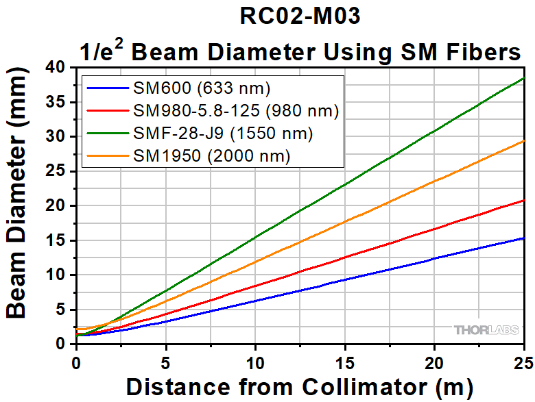
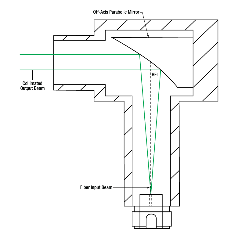
Collimating Light from a Multimode Fiber with a Reflective Collimator
Click to Enlarge
Low-NA Fiber: The green line indicates the envelope of the beam as it diverges and is collimated by the OAP mirror.
Click to Enlarge
High-NA Fiber: The red line indicates the envelope of the beam that is clipped by the collimator housing. The dashed green line shows the portion of the beam that is collimated by the OAP mirror.
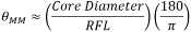
The geometrical ray model can be used to describe the collimation of light from multimode (MM) fibers. Consider an off-axis point on the MM core. Light from this point will generate a collimated beam at an angle to the optical axis of the off-axis parabolic (OAP) mirror. Superimposing beams from all points on the MM core results in an output beam with significant divergence, unlike the output from the SM fiber described above. The graph below shows the calculated beam diameter as a function of distance from the reflective couplers for three different MM fibers.
Theoretical Approximation of the Divergence Angle of an Output Beam
The full angle divergence of an output beam generated from a MM fiber can be approximated with the help of the reflected focal length (RFL) of the reflective collimator and the core diameter of the MM fiber as follows:
where θMM is the divergence angle of the beam after collimation, calculated in degrees.
Example Calculation:
When the RC02SMA-M03 collimator (RFL = 7.0 mm) is used with the M14L01 MM patch cable (Core Diameter = 50 µm), the full divergence angle is:
θMM ≈ (0.050 mm / 7.0 mm) x (180 / 3.1416) ≈ 0.41° or 7.1 mrad.
Theoretical Approximation of the Output Beam Diameter
Based on the ray model, the beam diameter as a function of distance from the reflective collimator and NA can be approximated with the following relation:

The equation above shows that the beam diameter is more strongly affected by the numerical aperture (NA) of the fiber close to the reflecting mirror, whereas the core diameter more strongly affects the beam diameter far from the collimator.
The graph below illustrates the approximated beam diameter as a function of the distance from the collimator for three different MM fibers (FG010LDA, FG025LJA, FG105LVA), all with an NA = 0.1. These results are independent of wavelength and connector type, but depend on the reflected focal length of the collimator.
Using MM fibers with NA >0.40 for the RC02x-M03 collimators will cause light to be clipped by the housing of the collimators before it reaches the output. Therefore, when collimating light from a MM patch cable, the fiber NA should be ≤0.40 for the RC02x-M03 collimator to avoid clipping light on the housing.
Aside from all these considerations based on simple paraxial optics, please keep in mind that a perfect off-axis parabola can only collimate light without aberrations from a point source, located at the mirror's focal point. The further the point is away from the optical axis or the larger the core of the MM fiber, the larger the introduced optical aberrations for the off-axis rays of the extended source. Finally, the off-axis points of the extended source cannot be perfectly collimated. The effects of aberrations can, however, be minimized by increasing the reflected focal length of the reflective collimator or by increasing the wavelength.
Click to Enlarge
Click Here for Theoretical Data
This data is calculated for our FG010LDA, FG025LJA, and FG105LVA multimode fibers
and our RC02x-M03 reflective collimators, independent of wavelength.

Insights:軸外放物面(OAP)ミラー
こちらのページでは軸外放物面(OAP)ミラーの利点や使用方法についてご覧いただけます。
- なぜ球面ミラーの代わりに放物面ミラーを使うのか?
- 軸外放物面ミラーの利点
- OAPミラーをベースにした反射型コリメータにおける光の方向性
このほかにも実験・実習や機器に関するヒントをまとめて掲載しています。こちらからご覧ください。
なぜ球面ミラーの代わりに放物面ミラーを使うのか?
Click to Enlarge
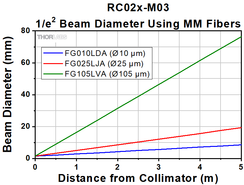
図2:球面ミラーでは、コリメート光のすべての光線が1つの点を通過するように反射することはできません。焦点体積内での光線同士の交差点を、いくつか選んで黒点で示しています。
Click to Enlarge
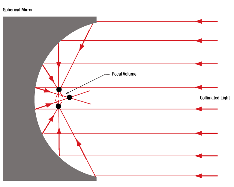
図1:放物面ミラーでは、コリメート光のすべての光線が1つの焦点に集められます。
放物面ミラーは、点光源からの光をコリメートしたりコリメート光を集光したりする場合には、球面ミラーよりも優れた性能を有します。
コリメート光の集光
放物面ミラー(図1)を用いると、コリメートされている入射光を回折限界スポットに集光することができます。 これに対して球面ミラー(図2)を用いた場合は、コリメートされている入射光を回折限界スポットよりも大きな体積のスポットにしか集光できません。球面ミラーのこの焦点体積(Focal Volume)の大きさは、コリメートされた入射ビームの径を小さくすることで小さくすることができます。
点光源からの光のコリメート
点光源からの光はすべての方向に放射されます。この発散光の光源を放物面ミラーの焦点に置くと、ミラーから出てくる光は非常に良くコリメートされています。理想的な点光源の場合、反射されたすべての光線は互いに完全に平行になります。
点光源を球面ミラーの焦点体積内に置いたときには、ミラーから出てくる光は放物面ミラーと比較してそれほど良くコリメートされません。点光源からの各光線は、球面ミラーで反射されたときには完全な平行にはなりませんが、球面ミラー表面上の近い点で反射された2本の光線は遠い点で反射された2本の光線よりも平行に近い状態になります。そのため、反射面積を小さくすればコリメート光としての品質は向上します。これは焦点体積内の光源から放射される光の角度範囲を制限することと等価です。
放物面ミラーと球面ミラーの選択について
放物面ミラーを選択するのが常に良いとは限りません。アプリケーションにおいて要求されるビーム径、コスト面の制約、スペース上の制限、性能要件など、すべてが選択に影響します。ビーム径が影響するのは、ビーム径が小さいと放物面ミラーと球面ミラーの性能が近くなるためです。放物面ミラーは反射部分の加工がより難しいため、球面ミラーより高価になります。また放物面ミラーのサイズは一般に球面ミラーよりも大きくなります。コストや物理的なサイズの違いに比べて、向上する性能が重要な場合もあれば、重要でない場合もあります。
最終更新日:2019年12月4日
軸外放物面ミラーの利点
Click to Enlarge
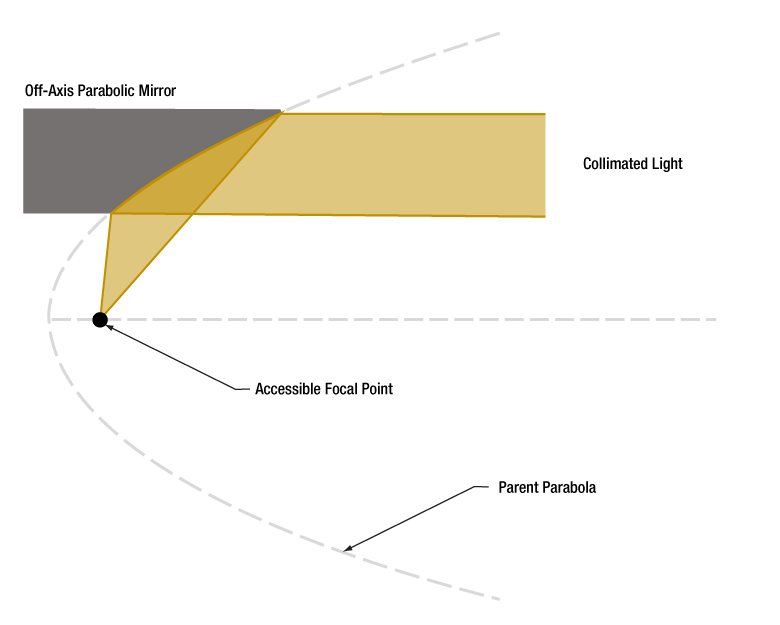
図4:軸外放物面(OAP)ミラーは、大きな放物面の一部分と考えられます。どちらも焦点は同じですが、OAPミラーのほうがよりアクセスしやすくなっています。
Click to Enlarge
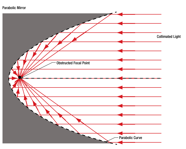
図3:通常の放物面ミラーの焦点は反射面に近く、また一般に反射面に囲まれているため、焦点にアクセスしにくくなっています。
放物面ミラーの主な利点の1つは、焦点が1つであることです。ミラー軸に対して平行に伝搬する光線は、反射されるとすべてこの点を通過します。これは、レーザ光を回折限界スポットに集光させることを要求されるイメージングや製造などの分野で、様々な目的に利用できます。
焦点周りに対称な通常の放物面ミラーを使用する場合、いくつかのマイナス面があります(図3)。1つは、一般にミラーの側面が妨げとなり、焦点にアクセスできないことです。もう1つは、ミラーを発散光のコリメートに使用したとき、光源の筐体がコリメート光の一部をブロックすることです。特にミラーの光軸に対して小さな角度で放射された光がブロックされます。
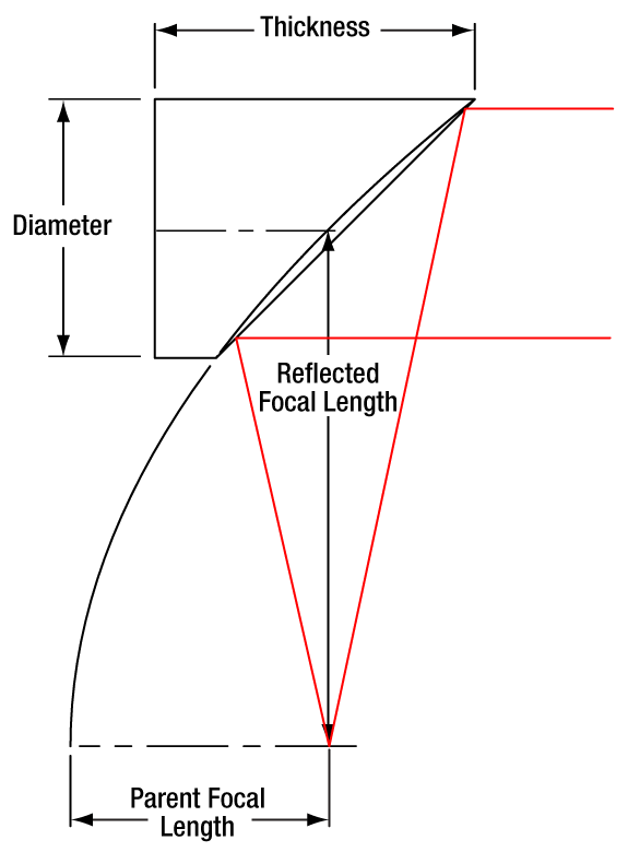
軸外放物面(OAP)ミラー(図4)を使用するのは、このような問題の解決策の1つです。このミラーの反射面の形状は放物面ですが、焦点周りに対称ではありません。OAPミラーの反射面は、焦点から離れた位置にある親放物面(Parent Parabola)上の一部分に対応します。どの部分の面を選択するかは、焦点とミラー中心間の角度や距離に対する要求に依存します。
最終更新日:2019年12月4日
OAPミラーをベースにした反射型コリメータにおける光の方向性
Click to Enlarge
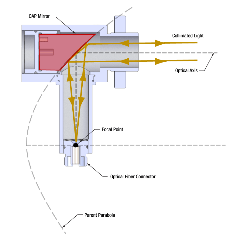
図6: コリメータの反射光学素子はOAPミラーです。ミラー基板は赤で示されています。この反射面は、放物面の頂点から離れた位置の放物面の一部分です。親放物面とOAPミラーの焦点は一致しています。
Click to Enlarge
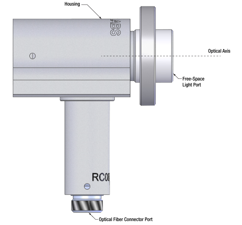
図5:当社ではファイバーコネクタ用のポートと、光軸に対して平行に伝搬するコリメートされた自由空間光用のポートを備えた、反射型コリメータをご用意しています。
当社の反射型コリメータの2つのポートは入れ替えることができません。1つのポートには光ファイバのコネクタを取付けますが、そこでは発散光を放出する点光源であることが要求されます。もう1つのポートはコリメートされた自由空間光用として設計されています(図5参照)。
自由空間光用ポート
このポートに入射する光は、光軸に対して平行なコリメート光でなければなりません。ファイバ端面、半導体レーザやその他の光源などからの発散光は入射しないでください。そのような光はファイバーコネクタ用のポートではコリメートされておらず、またファイバーポートに接続されたファイバに結合もされません。
ファイバーコネクタ用ポート
このポートではファイバの端面がミラーの焦点にアライメントされます。ファイバの端面は焦点に置かれた点光源に近いため、自由空間ポートからはコリメートされたビームが出射されます。ファイバ端面を焦点にアライメントすることは、自由空間光用ポートからの光がコリメートされ、光軸に対して平行に出射される理由でもあります。
光の方向性について
コリメータにおける光の方向は、反射素子として回転非対称の軸外放物面(OAP)を使用していることで決まっています(図6)。断面図では、ファイバの端面がOAPミラーの焦点でもある親放物面の焦点に置かれていることを示しています。
最終更新日:2019年12月4日
| Posted Comments: | |
| No Comments Posted |
ファイバーコリメーターセレクションガイド
コリメータの種類または画像をクリックすると、各コリメータの詳細がご覧いただけます。
| Type | Description | |
|---|---|---|
| 焦点固定型FC、APC、SMAファイバーコリメータ | 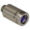 | こちらのファイバーコリメーターパッケージは、FC/PC、FC/APC、またはSMAコネクタ付きファイバからの出射光をコリメートするように、予めアライメントされています。各コリメーターパッケージは、405 nm~4.55 µmの波長で回折限界性能が得られるように工場で調整されています。設計波長以外でコリメータを使用することは可能ですが、色収差が生じるため最適な性能が得られるのは設計波長においてのみです。非球面レンズの実際の焦点距離は、色収差により波長に依存します。 |
| エアスペース型複レンズ、大径ビームコリメータ | 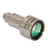 | 大径ビーム(Ø5.3 mm~Ø8.5 mm)用として、FC/PC、FC/APC、SMAコネクタ付きエアスペース型複レンズコリメータをご用意しています。こちらのコリメーターパッケージは、FCやSMAコネクタ付きファイバからの出射光をコリメートし、設計波長で回折限界性能が得られるように工場で予めアライメントされています。 |
| トリプレットレンズコリメータ | 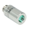 | 高品質なトリプレットコリメーターパッケージは、エアスペース型トリプレットレンズを使用しており、非球面レンズを用いたコリメータよりも優れたビーム品質が得られます。収差の小さいトリプレットを用いることの利点は、M2値として1(ガウシアン)に近い値が得られ、広がり角や波面エラーが小さくなることなどです。 |
| マルチモードファイバ用アクロマティックコリメータ | 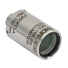 | 高NAアクロマティックコリメータは、メニスカスレンズとアクロマティック複レンズを組み合わせることで、可視~近赤外スペクトル域において球面収差の少ない優れた性能を発揮します。高NAのマルチモードファイバ用に設計されているため、オプトジェネティクスやファイバーフォトメトリの用途に適しています。 |
| 反射型コリメータ | 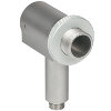 | 金属コーティング反射型コリメータは、90°軸外放物面(OAP)ミラーをベースにしています。レンズと違い、ミラーは広い波長範囲にわたり焦点距離が変化しません。この特性により、軸外放物面(OAP)ミラーを用いたコリメータは広い波長範囲に対応させるための調整が不要となるため、多色光を用いる用途に適しています。当社の反射型コリメータはシングルモードファイバからの光のコリメートには適していますが、シングルモードファイバへの結合には適していません。これらのコリメータにはUV強化型アルミニウムコーティングと保護膜付き銀コーティングの製品をご用意しており、それらにはFC/PC、FC/APCまたはSMAコネクタが取り付けられています。 |
| コンパクト反射型コリメータ |  | このコンパクトな反射型コリメータには、保護膜付き銀コーティングが施された90°軸外放物面(OAP)ミラーが組み込まれています。OAPミラーの焦点距離は波長に依存しないため、多色光用として適しています。 この固定式の反射型コリメータは、シングルモードファイバやマルチモードファイバからの出射光のコリメート用、およびマルチモードファイバへの光結合用として推奨しています。 これらのコリメータは当社の16 mmケージシステムに直接取り付けられます。 光入射用として、FC/PC、FC/APCまたはSMAコネクタの取り付けられた製品をご用意しています。 |
| 調整機能付き反射型コリメータ |  | 調整機能付き反射型コリメータは、保護膜付き銀コーティングが施された90°軸外放物面(OAP)ミラーをベースにしています。ファイバ-OAP間の距離が調整可能であり、またOAPミラーが波長によらず一定の焦点距離を有します。そのため、シングルモードまたはマルチモードファイバからの多色光をコリメートしたり、あるいは逆に多色光をそれらのファイバに結合したりすることができ、その際に最適化のための調整も可能です。これらの調整機能付きコリメータは15.0 mmまたは33.0 mmの反射焦点距離を有し、FC/PC、FC/APC、またはSMAコネクタ付きの製品をご用意しています。 |
| FiberPort |  | こちらのコンパクトで極めて安定なFiberPortマイクロポジショナは、FC/PC、FC/APCまたはSMAコネクタ付き光ファイバとの光の入出射用として、安定で使いやすいプラットフォームです。シングルモード、マルチモードまたは偏波保持ファイバと組み合わせて使用することができ、ポスト、ステージ、プラットフォーム、レーザなどに取り付けることができます。組み込まれている非球面またはアクロマティックレンズのARコーティングは5種類から選択でき、また5軸のアライメント調整(3つの移動調整と2つの角度調整)が可能です。コンパクトでアライメントの長期安定性に優れたFiberPortは、ファイバへの光の結合、コリメート、組み込み用途(OEM用途)などに適しています。 |
| 調整可能型ファイバーコリメータ |  | このコリメータは、FC/PC、FC/APCまたはSMAコネクタに接続するよう設計されており、内部にはARコーティング付き非球面レンズが取付けられています。非球面レンズとファイバ先端との距離は、焦点距離の変化を補正したり、波長や対象までの距離に合わせて再コリメートしたりするために調整することができます。 |
| アクロマティックファイバーコリメータ、焦点調整可能 |  | 焦点調整の可能な当社のアクロマティックファイバーコリメータは、20 mm、40 mmまたは80 mmの有効焦点距離(EFL) を有し、その光学素子のARコーティングは3種類の広帯域ARコーティングから選ぶことができます。また、接続用コネクタの種類としては、FC/PC、FC/APCまたはSMA905をご用意しています。4枚のレンズを使用したエアスペース型設計であるため、非球面レンズのコリメータに比べてビーム品質に優れ(1に近いM2)、波面誤差は小さくなっています。これらのコリメータは自由空間光のファイバへの結合や、ファイバからの出射光のコリメートなどにご使用いただけます。また、距離をとって配置した2つのコリメータを用いて光を結合させると、光が2番目のコリメータに入る前にそのビームを操作することが可能になります。 |
| ズーム機能付きファイバーコリメータ | 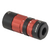 | こちらのコリメータは、ビームをコリメートしたまま、6~18 mmの範囲で焦点距離を変えることができます。そのため、コリメートした状態でビームサイズを変更できます。このデバイスは、用途に適した固定のファイバーコリメータを探す手間を省けるという利点に加え、1つで様々な幅広い用途に対応することができます。FC/PC、FC/APCまたはSMA905コネクタが付いており、反射防止コーティングは3種類からお選びいただけます。 |
| シングルモードファイバーピグテール付きコリメータ |  | シングルモードファイバーピグテール付きコリメータは、長さ1メートルのファイバとそれに対して予めアライメントされたARコーティング付き非球面レンズとで構成されており、532 nm、633 nm、780 nm、850 nm、1030 nm、1064 nm、1310 nm、1550 nmの8波長用の製品をご用意しています。コーティング波長域内のどの波長でもコリメートできますが、設計波長からずれると結合損失が増加します。 |
| 偏波保持ファイバーピグテール付きコリメータ |  | 偏波保持ファイバーピグテール付きコリメータは、長さ1メートルのファイバとそれに対して予めアライメントされたARコーティング付き非球面レンズとで構成されており、633 nm、780 nm、980 nm、1064 nm、1550 nmの5波長用の製品をご用意しています。波長やコネクタについてはカスタム仕様も対応可能です。筐体の外側にはスロー軸と平行なラインが刻印されています。これは入射光の偏光面をアライメントする際の目安としてお使いいただけます。コーティング波長域内のどの波長でもコリメートできますが、設計波長からずれると結合損失が増加します。 |
| GRINレンズコリメータ |  | GRINレンズファイバーコリメータは、630~1550 nmの範囲内の様々な波長に対してアライメントされた製品をご用意しており、FCまたはAPCコネクタ付きもしくはコネクタ無しのタイプからお選びいただけます。この有効径Ø1.8 mmのGRINレンズコリメータは、ファイバへの後方反射光を抑えるためにARコーティングが施されており、標準のシングルモードファイバまたはグレーデッドインデックス(GI)マルチモードファイバに結合されています。 |
| GRINレンズ |  | この屈折率分布型(GRIN)レンズは630 nm、830 nm、1060 nm、1300 nm、または1560 nmの波長用にARコーティングが施されており、光ファイバから出射した光が自由空間の光学系を通過して再度別のファイバに入射するまでの各用途にご利用いただけます。また半導体レーザの出射光のファイバへの結合、ファイバからの出射光のディテクタへの集光、レーザ光のコリメートなどにも適しています。このGRINレンズは当社の ピグテール付きガラスフェルールやGRINレンズ/フェルール用スリーブと組み合わせてお使いいただくこともできます。 |