 Products Home
手動回転ステージ
- Continuous 360° Rotation
- Ø1", Ø1.4", Ø2", or Ø4.3" Rotating Platform
- Backlash-Free, Low-Profile Design
RP01
Ø2" Manual
Rotation Stage
MSRP01
Ø1.4" Manual
Rotation Stage
RP005
Ø1" Manual
Rotation Stage
1/4" (M6) Counterbores for Mounting to an Optical Table or Breadboard
#4 (M3) Counterbores for Mounting to a Mini-Series Breadboard
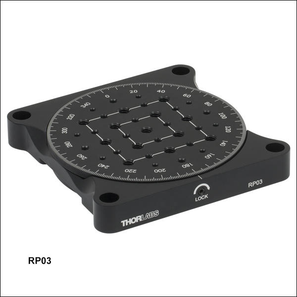
RP03
Ø4.3" Manual
Rotation Stage


Please Wait
| Rotation Stage Comparison | ||||
|---|---|---|---|---|
| Item # | RP005(/M) | MSRP01(/M) | RP01(/M) | RP03(/M) |
| Rotating Platform Size | Ø1.00" (25.4 mm) | Ø1.40" (35.6 mm) | Ø2.07" (52.8 mm) | Ø4.29" (109.0 mm) |
| Component Mounting Taps | Six 4-40 (M3) One 1/4"-20 (M6) | Four 4-40 (M3) One 8-32 (M4) | Four 8-32 (M4) One 1/4"-20 (M6) | Eight 6-32 (M4) Sixteen 8-32 (M4) Thirteen 1/4"-20 (M6) |
| Side Tap for Post Mounting | No | Yes; 4-40 (M3) | Yes; 8-32 (M4) | Yes; 8-32 (M4) |
| Stage Height | 0.67" (17.0 mm) | 0.51" (13.1 mm) | 0.63" (16.1 mm) | 0.70" (17.8 mm) |
| Stage Dimensions | 1.50" x 1.50" (38.1 x 38.1 mm) | 1.78" x 1.40" (45.2 x 35.6 mm) | 2.45" x 2.45" (62.2 x 62.2 mm) | 4.65" x 4.65" (118.1 x 118.1 mm) |
特長
- 360°連続回転
- 2°単位のレーザ刻印目盛付き
- 取付けプラットフォームサイズ:Ø25.4 mm、Ø35.6 mm、Ø52.8 mm、Ø109.0 mm
- ブレッドボード取付け用M6またはM3ザグリ穴
- 側面の止めネジ(セットスクリュ)で固定可能
手動回転ステージは費用効率の高いプラットフォームで、滑らかでバックラッシュのない回転を必要とするオプトメカニクス部品用の製品です。ステージは360°連続回転し、取付けプラットフォームはØ25.4 mm、Ø35.6 mm、Ø52.8 mm、Ø109.0 mmのサイズをご用意しております。 回転プラットフォームの縁に沿って刻印されている角度目盛により、ステージの角度方向を設定することが可能です。プラットフォームの回転は側面の止めネジを締め付けることで固定できます。四隅に付いているザグリ穴は、光学テーブルまたはブレッドボードに直接取り付けられるように、その間隔が設定されています。
当社ではこのほかにもマイクロメータ駆動の手動式ステージや、中央に貫通穴のあるステージ、ハードストップ付きのステージなどをご用意しております。当社の回転ステージのラインナップについては「回転マウントとステージ」タブをご覧ください。
バーニヤ目盛の読み方:主目盛が直線状の場合
バーニヤ目盛は、均等に分割された標準的な目盛(当社の回転マウント、ゴニオステージ、移動マウントに付いている目盛など)に対して、精密さを向上させるために一般的に使用されている目盛です。バーニヤ目盛は多くの精密測定器に使用されていますが、中でも良く知られているのはノギスやマイクロメータです。バーニヤ目盛を使用するときは、主目盛とバーニヤ目盛の2つの目盛を並べて使用します。バーニヤ目盛は、主目盛のN - 1目盛に対してN目盛が対応するように刻まれているため、その間隔は主目盛よりも若干狭くなります。そのため、主目盛の刻線とバーニヤ目盛の刻線とは一致しません。バーニヤ目盛の刻線で主目盛の刻線と最も良く一致するのは通常1本だけですが、それがバーニヤ目盛を読む要所になります。
図1~3では、直線状のバーニヤ目盛の仕組みについて3つの例をあげて説明しています。これらの図では、左側が主目盛で右側の小さい目盛がバーニヤ目盛です。バーニヤ目盛を読むときは、まず主目盛で大まかな数値を読み取り、次にバーニヤ目盛で精密な数値を読み取ります。この仕組みで、標準的なルーラやマイクロメータが精密な測定器になります。
バーニヤ目盛の0は「ポインタ」(図1~5で赤い矢印で表示)で、主目盛での読取値を示します。図1では、ポインタは主目盛の75.6の刻線と一致しています。これ以外で主目盛の刻線と一致しているバーニヤ目盛の刻線は、10だけであることに注目してください。ポインタが主目盛の75.6と一致しているので、図1から読み取れる値は75.60になります(どのような単位での測定でも同じです)。
これがバーニヤ目盛の読み取り方の基本です。バーニヤ目盛を用いると、簡単に測定器の精度を向上させることができます。図2で更に詳しくご説明します。ここではポインタは主目盛の刻線とは一致せず、75.6よりわずかに上側ですが75.7よりも下側にあります。この場合の大まかな読取値は75.6になります。主目盛と最も良く一致するバーニヤ目盛は5で、青い矢印で示されています。バーニヤ目盛は精密に読み取れる最小桁を示し、図2では5が主目盛と一致しているので、精密な測定値は75.65になります。
バーニヤ目盛は主目盛よりも10%小さくなっているので、バーニヤ目盛を主目盛の1/10だけ動かすと、バーニヤ目盛の次の刻線が一致します。ここで、測定値が1/10の精度を与えてくれるバーニヤ目盛の間にきてしまった場合はどうするのか、という疑問が生じます。図3ではこれについて説明しています。上述の通り、ポインタの刻線は75.6と75.7の間にあるので、大まかな読取値は75.6になります。よく見ると、バーニヤ目盛の7(青い矢印で表示)が主目盛とほぼ一致しているので、精密な測定値としては75.67になります。しかし、バーニヤ目盛の7は主目盛よりもわずかに上にあり、8(7のすぐ上)は主目盛よりもわずかに下にあります。このことから、図3の目盛は75.673 ± 0.002と読み取れます。この想定器では、読取誤差を約0.002とするのは適切です。
Click to Enlarge
図1:バーニヤ目盛の読み取り方の例。赤い矢印はポインタと呼ばれています。バーニヤ目盛の10が主目盛の1本と一致しているので、このバーニヤ目盛は75.60と読み取れます(どのような単位での測定でも同じです)。
Click to Enlarge
図2:赤い矢印はポインタを示し、青い矢印は主目盛と一致するバーニヤ目盛の刻線を示しています。この目盛では75.65と読み取れます。

Click to Enlarge
図3:赤い矢印はポインタを示し、青い矢印は主目盛と一致するバーニヤ目盛の刻線を示しています。これは75.67と読み取れますが、より精密には75.673 ± 0.002と読むことができます。
バーニヤ目盛の読み方:主目盛が回転式の場合
バーニヤ目盛は、主目盛とバーニヤ目盛が単位を共有していない回転式の目盛でも使用できます。図4と図5では、主目盛には度(°)を単位とする刻線があり、バーニヤ目盛には5 arcmin(60 arcmin = 1°)毎の刻線がある場合について、2つの例をあげて説明しています。これらの図では、上が主目盛を表し、下の小さい目盛がバーニヤ目盛を表します。
図4では、ポインタは主目盛の341°の刻線と一致しています。これ以外に主目盛と一致しているバーニヤ目盛は±60 arcminだけであることに注目してください。バーニヤ目盛の0が主目盛の341°と一致しているので、図4から読み取れる値は341.00°になります。
バーニヤ目盛の0が主目盛の2本の刻線の間にある場合は、2通りの読み取り方ができます。1つ目の方法では、ポインタの左側で主目盛と一致しているバーニヤ目盛の刻線を読み取り、その値(単位はarcmin)をポインタのすぐ右側にある主目盛の値から引きます。例として、図5ではバーニヤ目盛のポインタは342°と343°の間にあります。バーニヤ目盛の左側の青い矢印を使用して読むと、343° - 15 arcmin = 342.75°になります。2つ目の方法は、バーニヤ目盛のポインタの右側にある青い矢印から読み取った値を、主目盛のポインタより左側の小さな値に加える方法です。図5の右側の青い矢印を使用して読むと、342° + 45 arcmin = 342.75°になります。
このように、バーニヤ目盛を用いると標準的なスケール測定の精密さを向上させることができます。慣れるまでに少々時間がかかりますが、練習すれば非常に簡単に目盛を読めるようになります。順バーニヤ、逆バーニヤ*にかかわらず、すべてのバーニヤ目盛は同様の方法で読み取ることができます。
*逆バーニヤ目盛は目盛の間隔が主目盛よりも若干広く、主目盛のN + 1目盛に対してN目盛が対応するように刻まれています。

Click to Enlarge
図4: 主目盛の単位(度)とバーニヤ目盛の単位(arcmin)が異なる例。赤い矢印はポインタを示しています。この目盛では341.00°と読み取れます。
Click to Enlarge
図5:赤い矢印はポインタを示し、青い矢印はバーニヤ目盛で読み取れる精密な数値を示します。 この目盛では342.75°と読み取れます。
| Posted Comments: | |
SHASHIDHAR UPPIN
(posted 2022-12-01 22:14:52.113) Hi, is it possible to set the rotation angle at 0.5 deg interval by RP01. jdelia
(posted 2022-12-02 04:08:35.0) Thank you for contacting Thorlabs. The angle at which you can reliably move the stage is entirely reliant on the dexterity of the end user as this is strictly a hand-rotated device. That being said, 0.5 degree is quite small and it would be considerably easier to achieve this by using a rotation stage with a precision micrometer, such as PR01 for example. If by setting an interval you meant through some sort of software, then I would suggest looking at our selection of motorized rotation stages. andrew krajecki
(posted 2022-11-08 12:24:27.19) This is a rotation stage that I would like to purchase, I am wondering how well this stage holds its angle and whether or not a small jolt to this device would significantly alter the set angle. i.e. does this stage have mechanism to lock the set angle? ksosnowski
(posted 2022-11-08 02:23:58.0) Hello Andrew, thanks for reaching out to Thorlabs. For RP01, rotation can be locked by tightening the side-located Locking Screw using a 5/64" (2.0 mm) balldriver or hex key. We have not tested stability for specific jolts however this mechanism will help eliminate unwanted adjustments. Maxime Joos
(posted 2021-04-30 22:07:02.43) Dear,
We are implementing the stage RP03 in magnetic sensitive environments and are wondering if it would be possible to have a custom RP03 without any magnetic metals components.
Thank you,
Maxime Joos YLohia
(posted 2021-05-03 01:39:56.0) Hello Maxime, thank you for contacting Thorlabs. Custom items can be requested by clicking on the "Request Quote" button above. I have reached out to you directly to discuss the possibility of offering this. Maxime Joos
(posted 2020-12-10 14:14:15.257) Dear,
would it be possible to drill a clearance hole through
RP03? What would be the maximum diameter of this hole?
Maxime llamb
(posted 2020-12-11 10:49:26.0) Hi Maxime, thank you for contacting Thorlabs. The main rotating platform component of the RP03 is indeed the only component that takes up the middle space of the product as a whole. If you are ok with getting rid of the mounting holes with a clearance hole, you could ALMOST reach a Ø3" diameter thru hole before interfering with the next mating component, though of course eliminating all mounting features if doing so. Alternatively, perhaps our PR01 stage with a central thru hole could be useful. I have reached out to you directly to discuss your options further. Jonathan Twichell
(posted 2020-05-21 19:54:39.983) No specs on wobble, or stiffness, especially when mounted vertically. The load limits must be a torque, and a weight. Vertically I am allowed 22 kg. If I put 20 kg on a 1 (or 10) meter carbon fiber tube I'll break it for sure. Load limits are two torques and 3 forces on the Cartesian axis. The bearing accuracy is specified by wobble, flatness and eccentricity. These are mostly missing on the description of the rotary mounts. llamb
(posted 2020-05-26 10:04:01.0) Thank you for your feedback. We will certainly consider improving the spec presentation for clarity. The 50 lbs (22 kg) load for the RP03's vertical load spec was placed at approximately 6" away from the mounting surface during initial testing. I have reached out to you directly to discuss these specs and your application further. Graig Moore
(posted 2019-08-20 06:21:55.91) I am using the 2" RP01 manual rotation stage and I had to tighten the set screw all the way but when I took the set screw out I can barely turn the stage. Any ideas on how to fix this? llamb
(posted 2019-08-20 02:15:57.0) Thank you for contacting Thorlabs. This appears to have damaged the stage, so we have reached out to you directly to set up an RMA. Patrick.Rappersberger
(posted 2017-07-06 11:06:22.34) Is it acceptable to mount a horizontal one sided setup on RP01 and RP03?
I expect less than 10Nm torque and 2kg, but the center of gravity will be about 0.5m away from the rotation axis. tfrisch
(posted 2017-09-01 12:02:30.0) Hello, thank you for contacting Thorlabs. 0.5m is a much longer lever arm than we use to test the vertical specs. I will reach out to you directly to discuss your application and how to reduce that torque. user
(posted 2016-11-10 05:24:52.8) This product completly meet my need, however I think it would be usefull to add in the product description the size of the balldriver neeed to lock the platform. I had a bad surprise when I discivered that I had to make a second comand to get a balldriver of the correct size. tfrisch
(posted 2016-11-10 04:02:33.0) Hello, thank you for your feedback. I'll ask our Marketing team to add the 5/64" size of the ball driver to the web presentation. |
回転マウント&回転ステージのセレクションガイド
当社では手動式および電動式の回転マウントと回転ステージを豊富にご用意しております。回転マウントの内孔はØ12 mm~Ø12.7 mm(Ø1/2インチ)、Ø25 mm~Ø25.4 mm(Ø1インチ)、またはØ50 mm~Ø50.8 mm(Ø2インチ) の光学素子取付け用に設計されております*。また回転ステージには、様々な部品やシステムが取り付けられるようにタップ穴が配置されております。電動式は、DCサーボモータ、2相ステッピングモータ、あるいはElliptec™共振ピエゾモータにより駆動されます。いずれも360°の連続回転が可能です。
*下表のマウントは、Ø12.7 mm、Ø25.4 mm、Ø50.8 mmの光学素子に対して最適設計されています。Ø12.0 mm、Ø25.0 mm、Ø50.0 mmなどの少し小さい光学素子に対してもご使用いただけますが、光学素子の偏心が重要ではない用途でのご使用をお勧めします。
手動回転マウント
| Rotation Mounts for Ø1/2" Optics | |||||||
|---|---|---|---|---|---|---|---|
| Item # | MRM05(/M) | RSP05(/M) | CRM05 | PRM05(/M)a | SRM05 | KS05RS | CT104 |
| Click Photo to Enlarge | 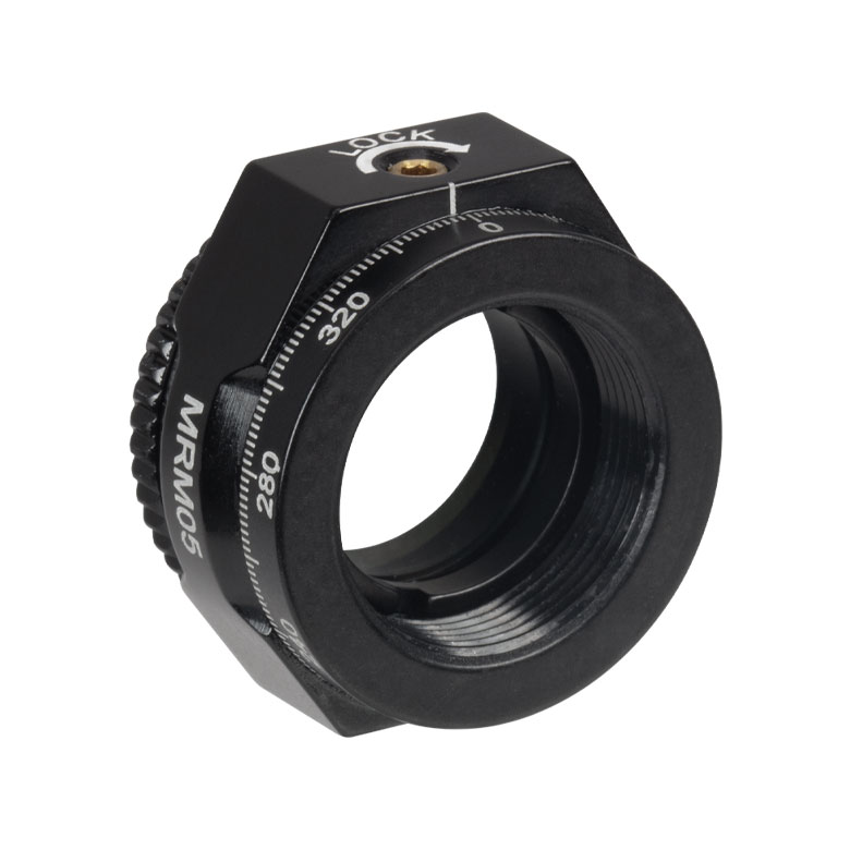 | 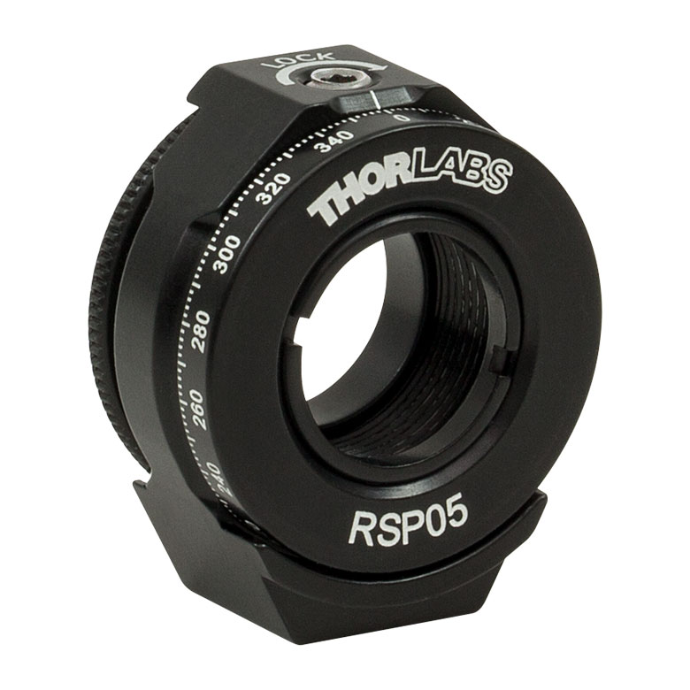 |  | 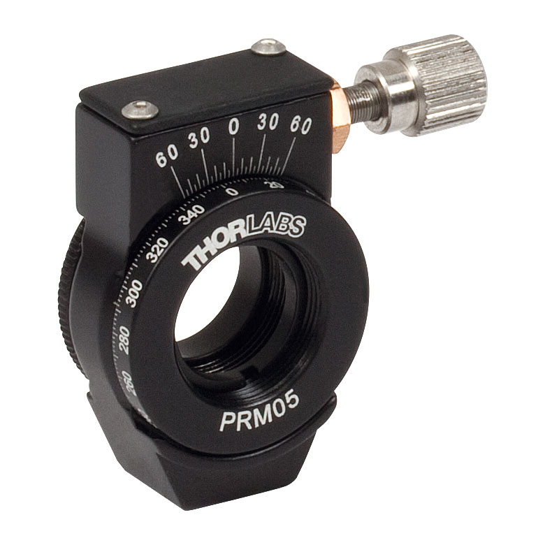 | 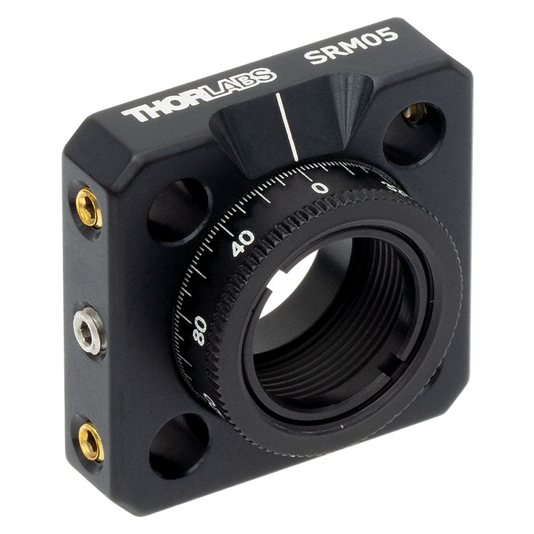 | 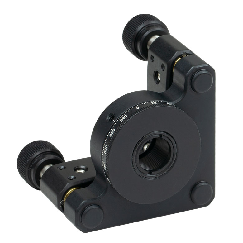 |  |
| Features | Mini Series | Standard | External SM1 (1.035"-40) Threads | Micrometer | 16 mm Cage-Compatible | ±4° Kinematic Tip/Tilt Adjustment Plus Rotation | Compatible with 30 mm Cage Translation Stages and 1/4" Translation Stagesb |
| Additional Details | |||||||
| Rotation Mounts for Ø1" Optics | ||||||||
|---|---|---|---|---|---|---|---|---|
| Item # | RSP1(/M) | LRM1 | RSP1D(/M) | DLM1(/M) | CLR1(/M) | RSP1X15(/M) | RSP1X225(/M) | PRM1(/M)a |
| Click Photo to Enlarge |  |  |  | 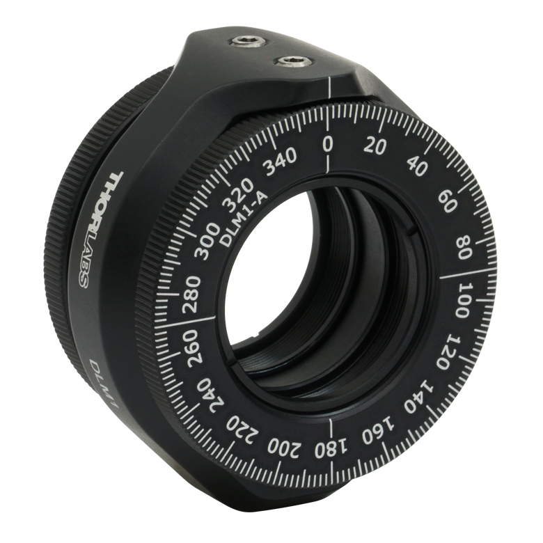 | 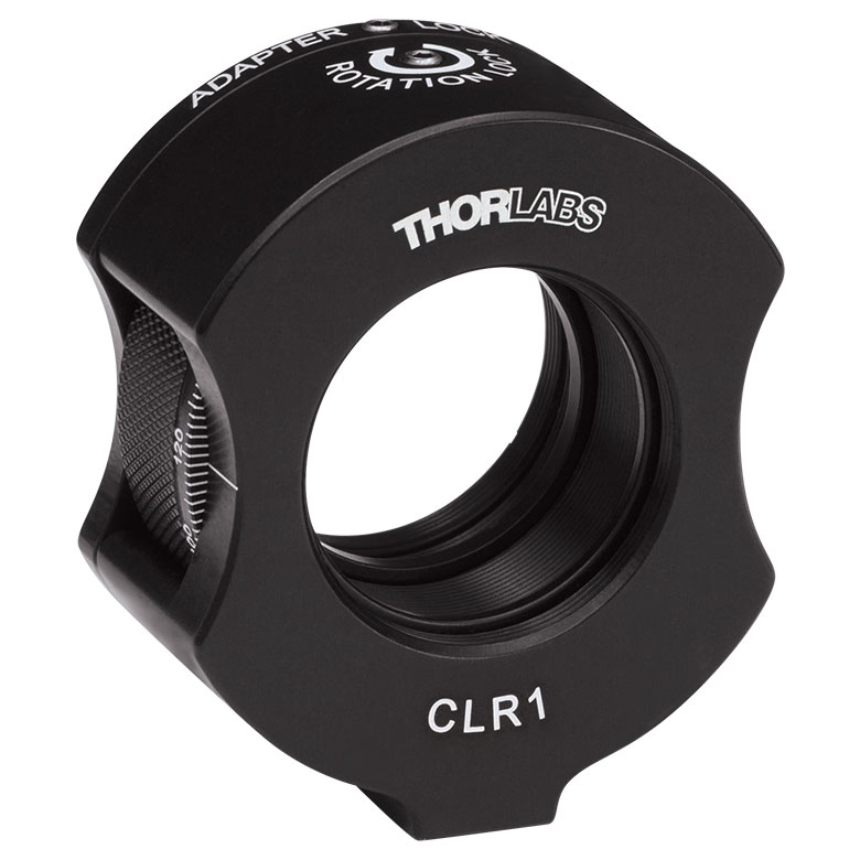 | 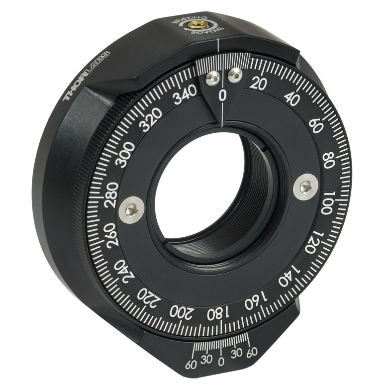 | | 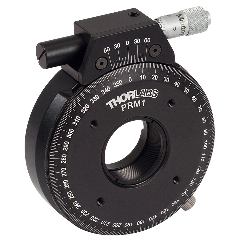 |
| Features | Standard | External SM1 (1.035"-40) Threads | Adjustable Zero | Two Independently Rotating Carriages | Rotates Optic Within Fixed Lens Tube System | Continuous 360° Rotation or 15° Increments | Continuous 360° Rotation or 22.5° Increments | Micrometer |
| Additional Details | ||||||||
| Rotation Mounts for Ø1" Optics | ||||||
|---|---|---|---|---|---|---|
| Item # | LM1-A & LM1-B(/M) | CRM1T(/M) | CRM1LT(/M) | CRM1PT(/M) | KS1RS | K6XS |
| Click Photo to Enlarge | 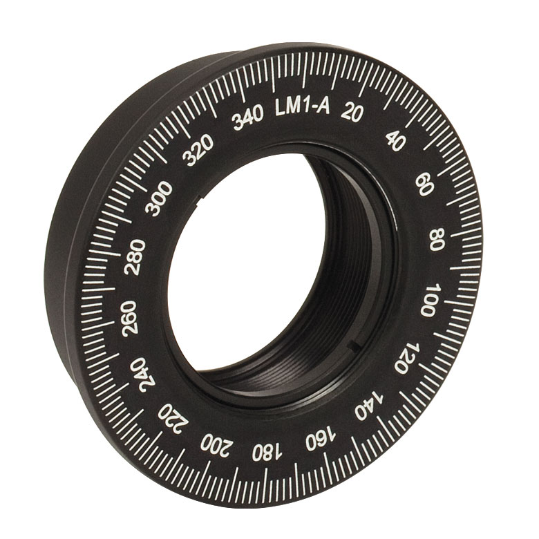 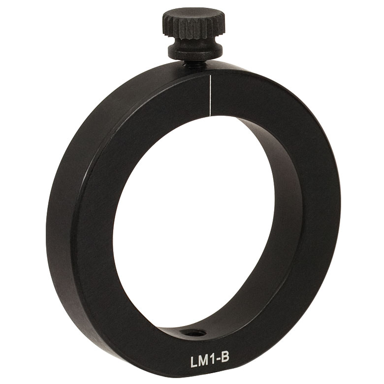 | 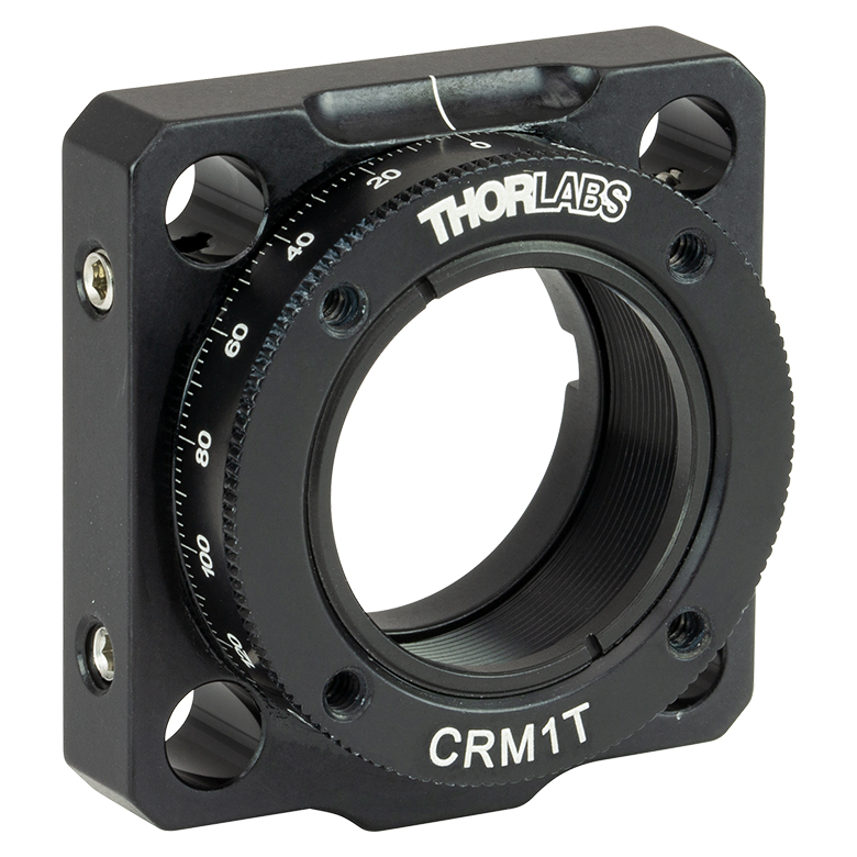 |  |  | 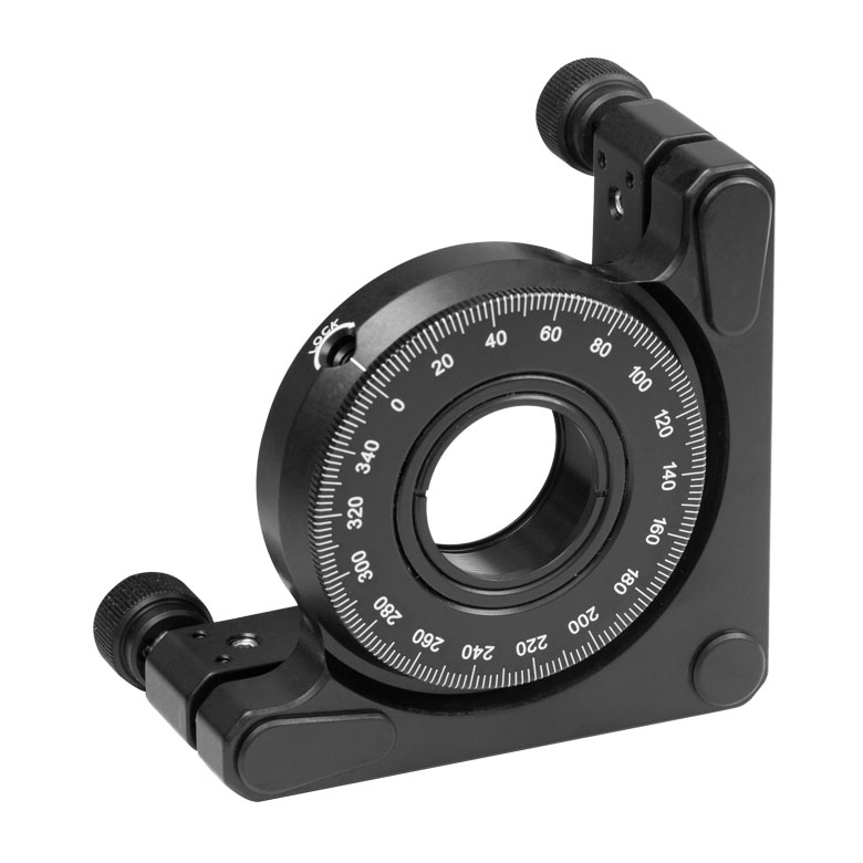 | 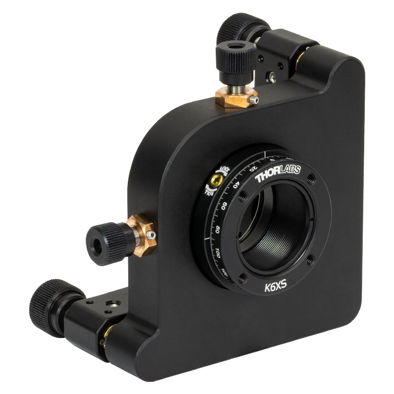 |
| Features | Optic Carriage Rotates Within Mounting Ring | 30 mm Cage-Compatiblea | 30 mm Cage-Compatible for Thick Opticsa | 30 mm Cage-Compatible with Micrometera | ±4° Kinematic Tip/Tilt Adjustment Plus Rotation | Six-Axis Kinematic Mounta |
| Additional Details | ||||||
| Rotation Mounts for Ø2" Optics | |||||||
|---|---|---|---|---|---|---|---|
| Item # | RSP2(/M) | RSP2D(/M) | PRM2(/M) | LM2-A & LM2-B(/M) | LCRM2A(/M) | KS2RS | K6X2 |
| Click Photo to Enlarge |  |  | 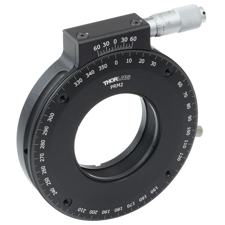 | 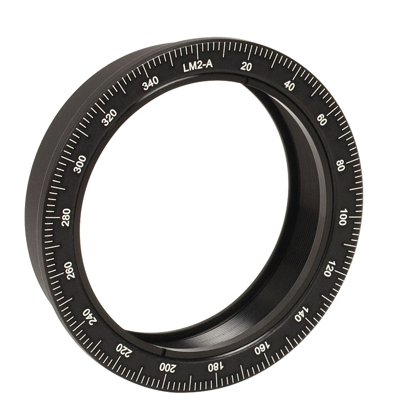 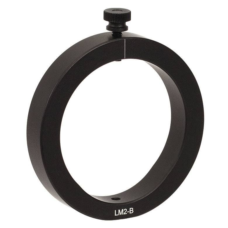 |  |  | 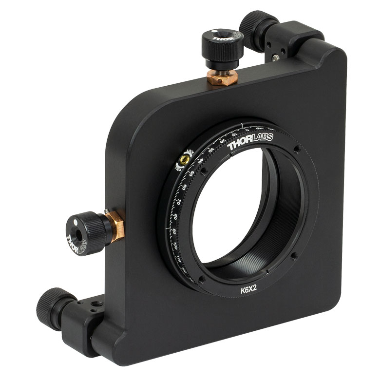 |
| Features | Standard | Adjustable Zero | Micrometer | Optic Carriage Rotates Within Mounting Ring | 60 mm Cage-Compatible | ±4° Kinematic Tip/Tilt Adjustment Plus Rotation | Six-Axis Kinematic Mount |
| Additional Details | |||||||
| Rotation Drive Mechanism and Adjustment Range | Manual, 360° Continuous | Coarse: Manual, 360° Continuous; Fine: ±7° Micrometer | Manual, 360° Continuous | ||||
| Optic Mounting | Internally SM2-Threaded Carriage | Internal SM2 Threads in LM2-A | Internally SM2-Threaded Carriage | ||||
| Maximum Accepted Optic Thickness | 0.51" (13 mm) | 0.54" (13.7 mm) | 0.48" (12.2 mm) | 0.46" (11.7 mm) | 0.52" (13.2 mm) | 0.47" (12 mm) | 0.53" (13.4 mm) |
| Post Mounting | 8-32 (M4) Tap | 8-32 (M4) Tap in LM2-B | 8-32 (M4) Tap | Four Counterbores for 8-32 (M4) Cap Screws | Six Counterbores for 8-32 (M4) Cap Screws | ||
| Cage System Compatibility | N/A | Four 4-40 (M3) Taps on Rotation Dial with 60 mm Spacing | N/A | Four Bores for Ø6 mm Cage Rods with 60 mm Spacing | N/A | N/A | |
手動回転ステージ
| Manual Rotation Stages | ||||||
|---|---|---|---|---|---|---|
| Item # | RP005(/M) | PR005(/M) | MSRP01(/M) | RP01(/M) | RP03(/M) | QRP02(/M) |
| Click Photo to Enlarge | 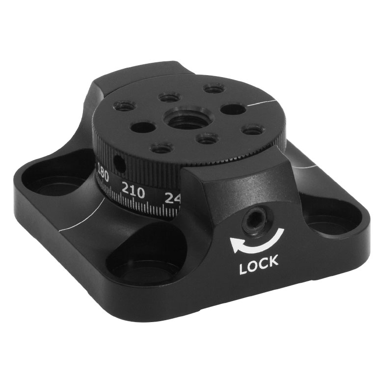 | 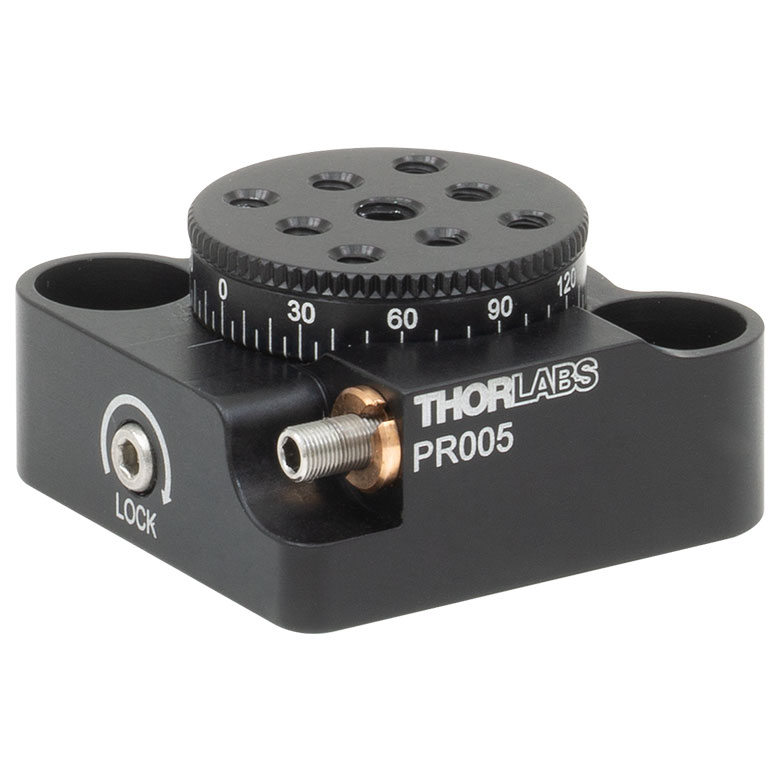 | 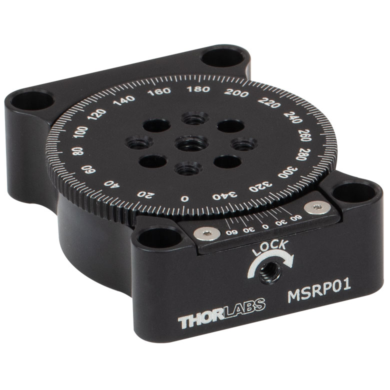 | 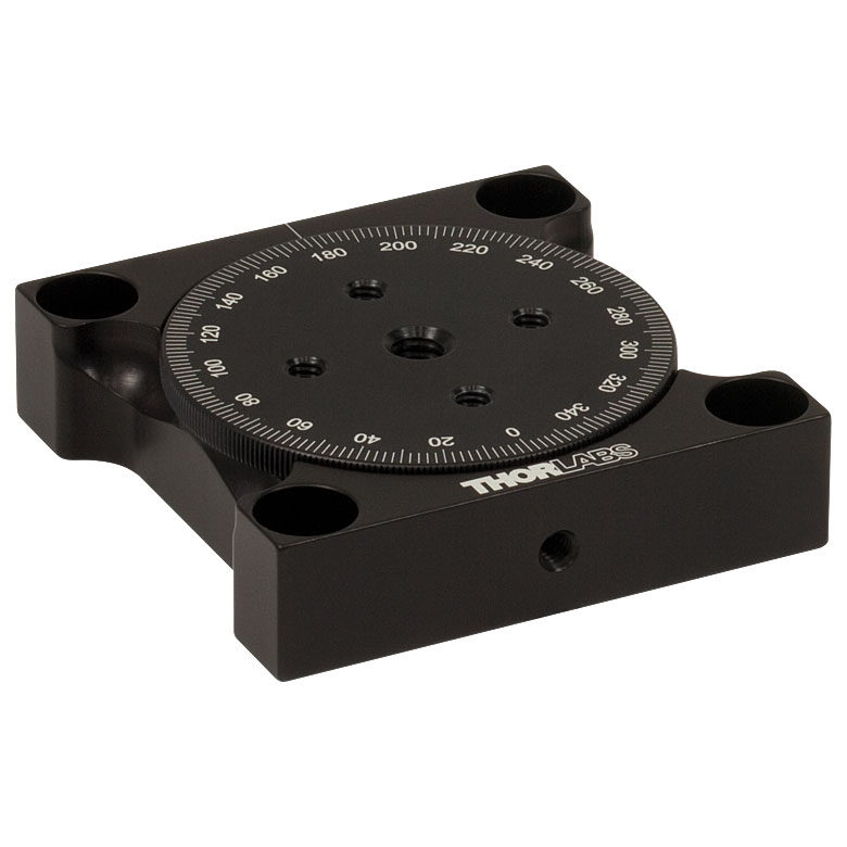 | 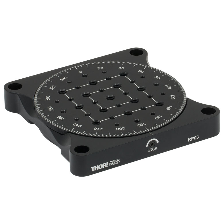 |  |
| Features | Standard | Two Hard Stops | ||||
| Additional Details | ||||||
| Manual Rotation Stages | ||||||
|---|---|---|---|---|---|---|
| Item # | XRNR1(/M) | XRR1(/M) | PR01(/M) | CR1(/M) | XYR1(/M) | OCT-XYR1(/M) |
| Click Photo to Enlarge | 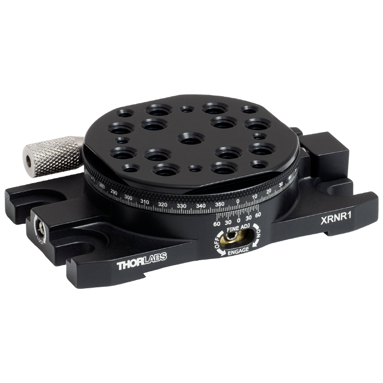 |  | 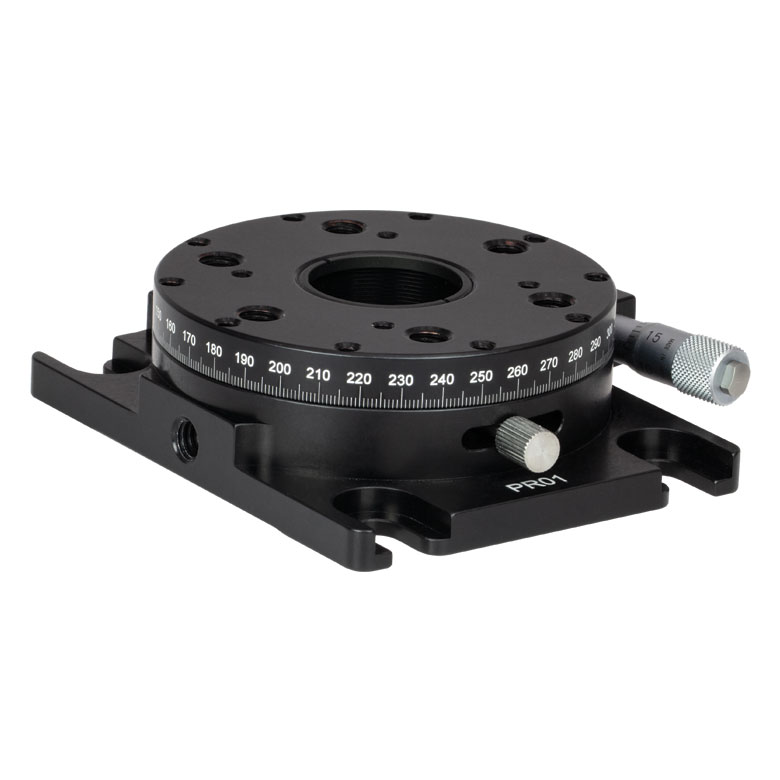 | 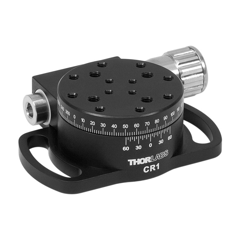 | 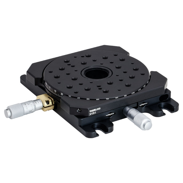 | 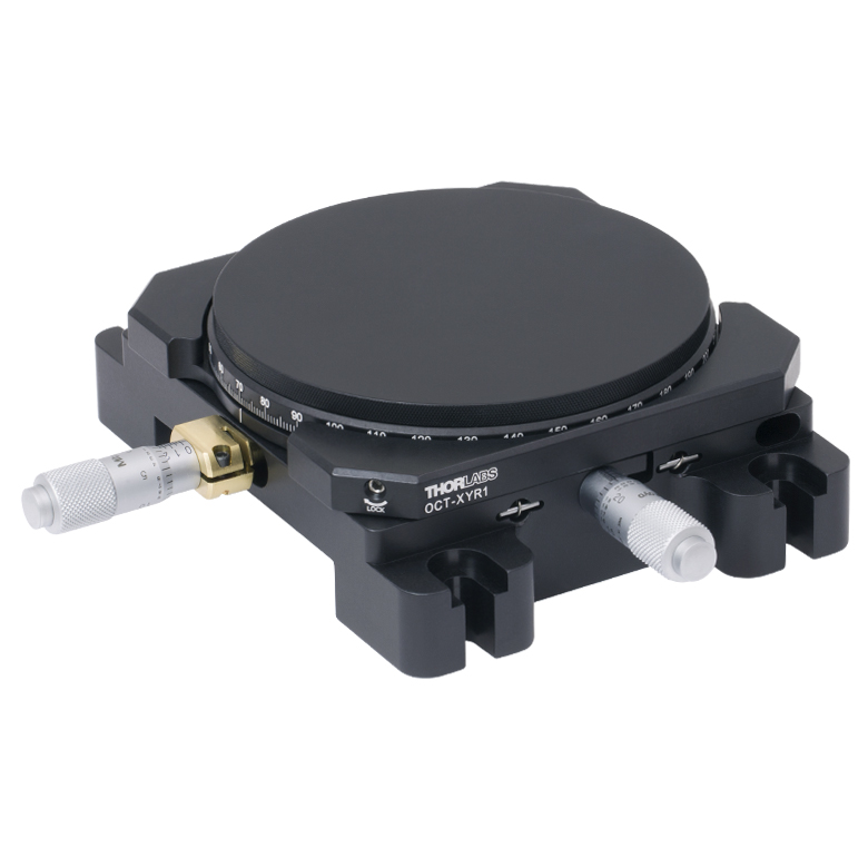 |
| Features | Fine Rotation Adjuster and 2" Wide Dovetail Quick Connect | Fine Rotation Adjuster and 3" Wide Dovetail Quick Connect | Fine Rotation Adjuster and SM1-Threaded Central Aperture | Fine Pitch Worm Gear | Rotation and 1/2" Linear XY Translation | |
| Additional Details | ||||||
電動回転マウント&ステージ
| Motorized Rotation Mounts and Stages with Central Clear Apertures | |||||
|---|---|---|---|---|---|
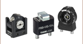
| Item # | DDR25(/M) | PDR1C(/M) | PDR1(/M) | PDR1V(/M) | PDXR1(/M) |
| Click Photo to Enlarge | 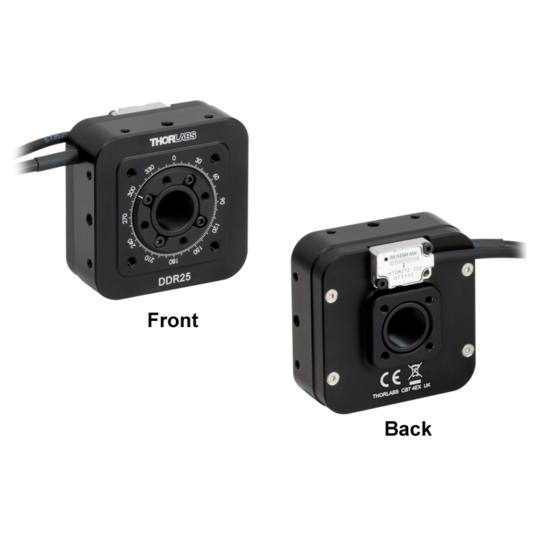 | 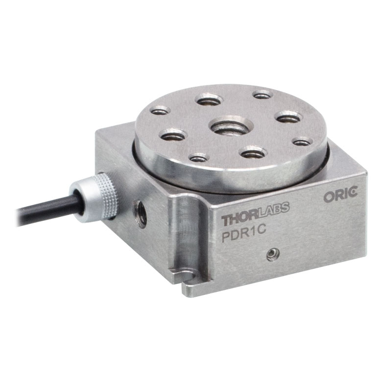 | 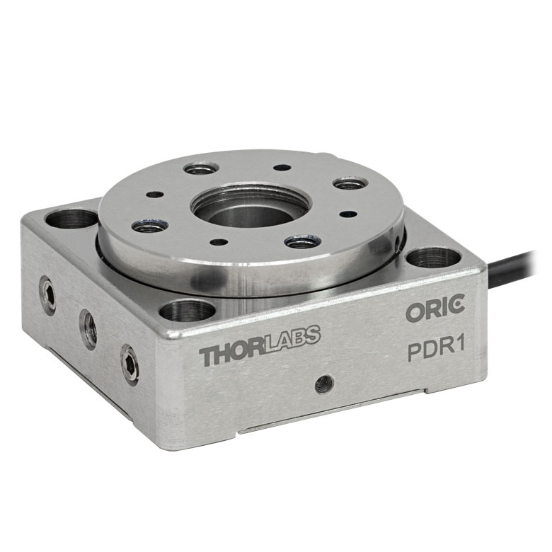 |  |  |
| Features | Compatible with SM05 Lens Tubes, 16 mm Cage System, & 30 mm Cage System | Compatible with 16 mm Cage System | Compatible with SM05 Lens Tubes & 30 mm Cage System | Vacuum-Compatible; Also Compatible with SM05 Lens Tubes & 30 mm Cage System | Compatible with SM05 Lens Tubes & 30 mm Cage System |
| Additional Details | |||||
| Motorized Rotation Mounts and Stages with Central Clear Apertures | |||||
|---|---|---|---|---|---|
| Item # | K10CR1(/M) | PRM1Z8(/M)a | DDR100(/M) | ELL14 | HDR50(/M) |
| Click Photo to Enlarge | 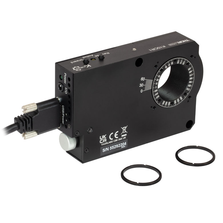 | 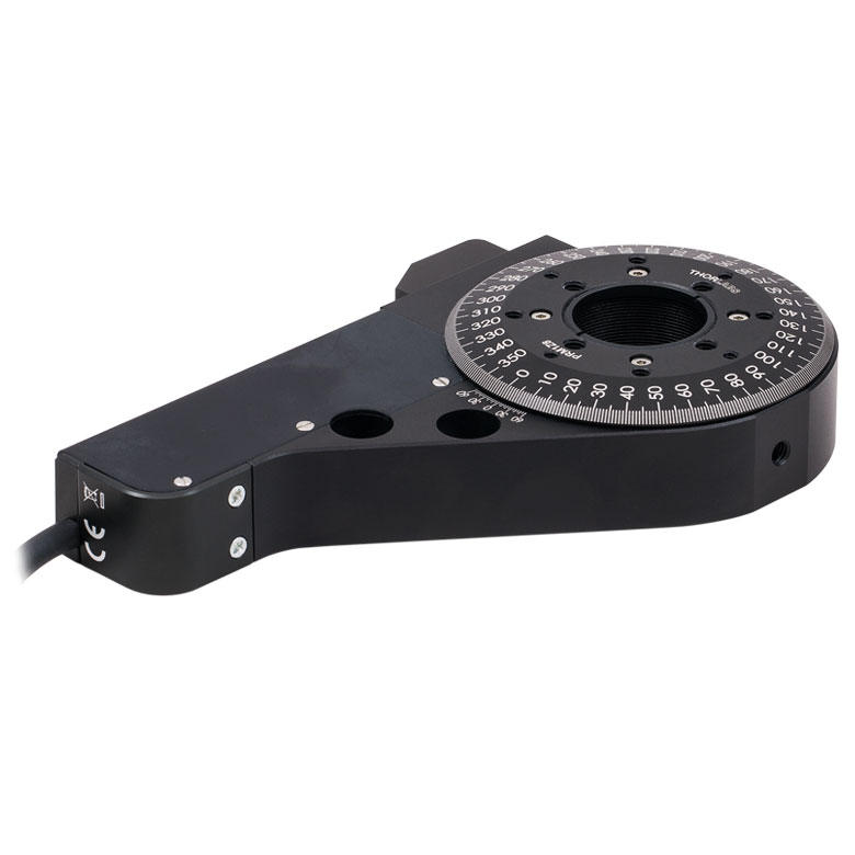 | 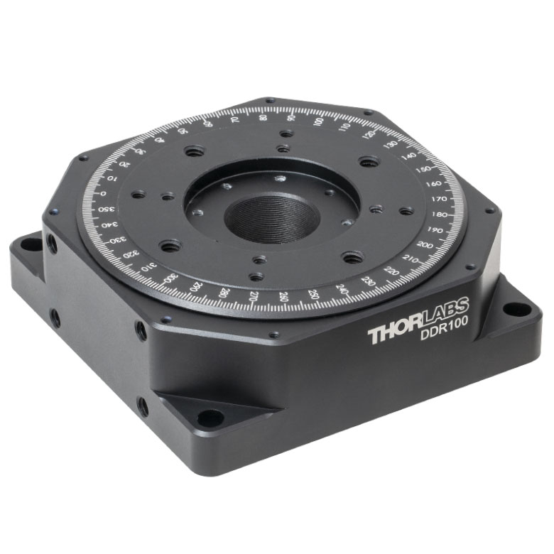 | 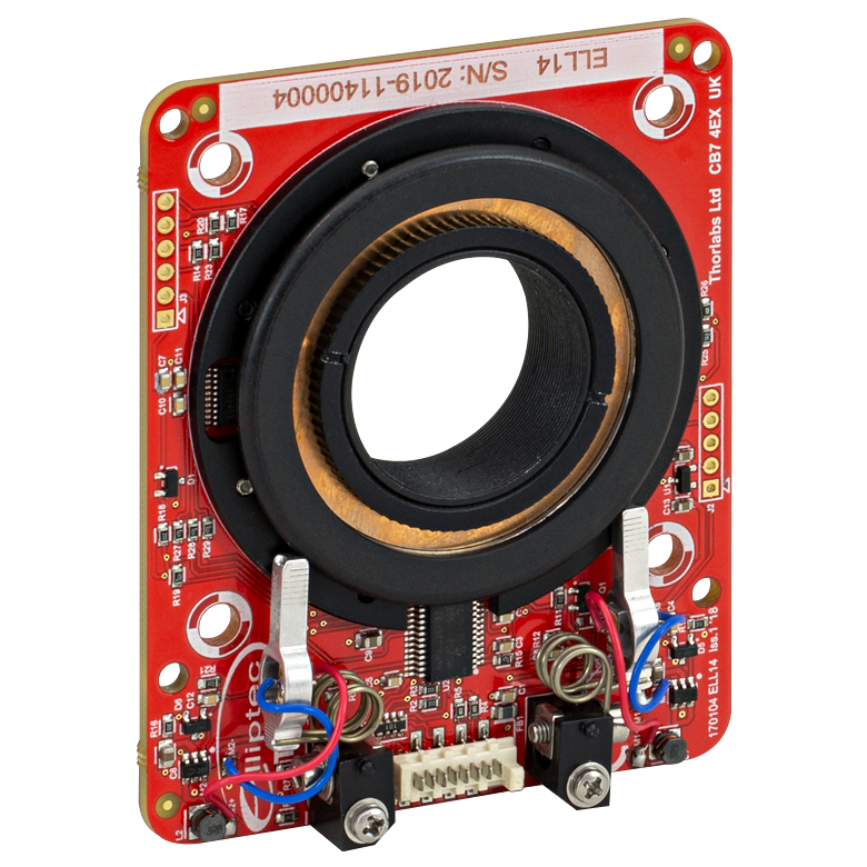 | 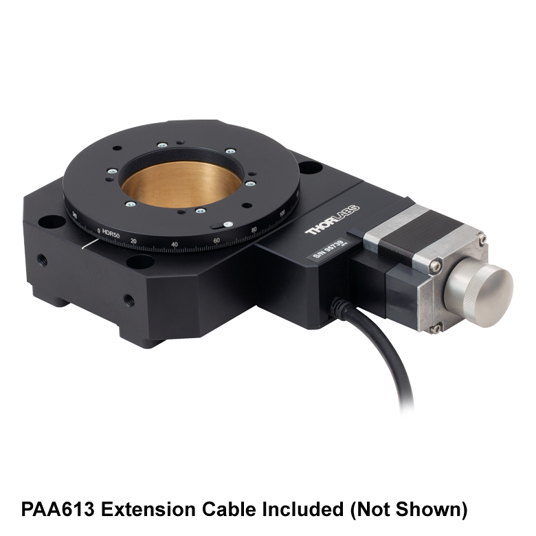 |
| Features | Compatible with SM1 Lens Tubes & 30 mm Cage System | Compatible with SM1 Lens Tubes, 16 mm Cage System, 30 mm Cage System | Compatible with SM1 Lens Tubes, Open Frame Design for OEM Applications | Compatible with SM2 Lens Tubes | |
| Additional Details | |||||
| Motorized Rotation Mounts and Stages with Tapped Platforms | ||
|---|---|---|
| Item # | PRMTZ8(/M)a | ELL18(/M)b |
| Click Photo to Enlarge | 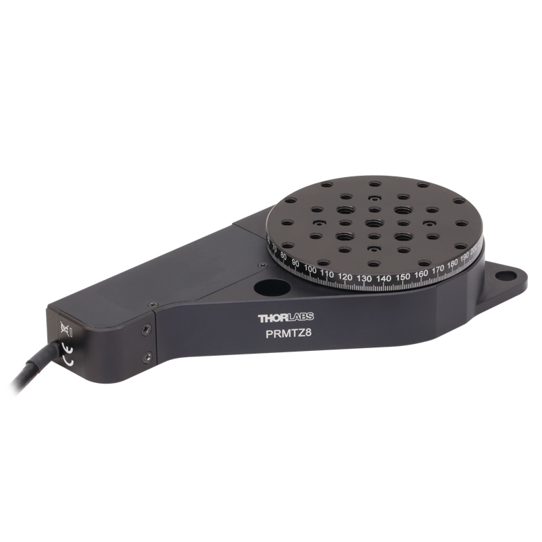 | 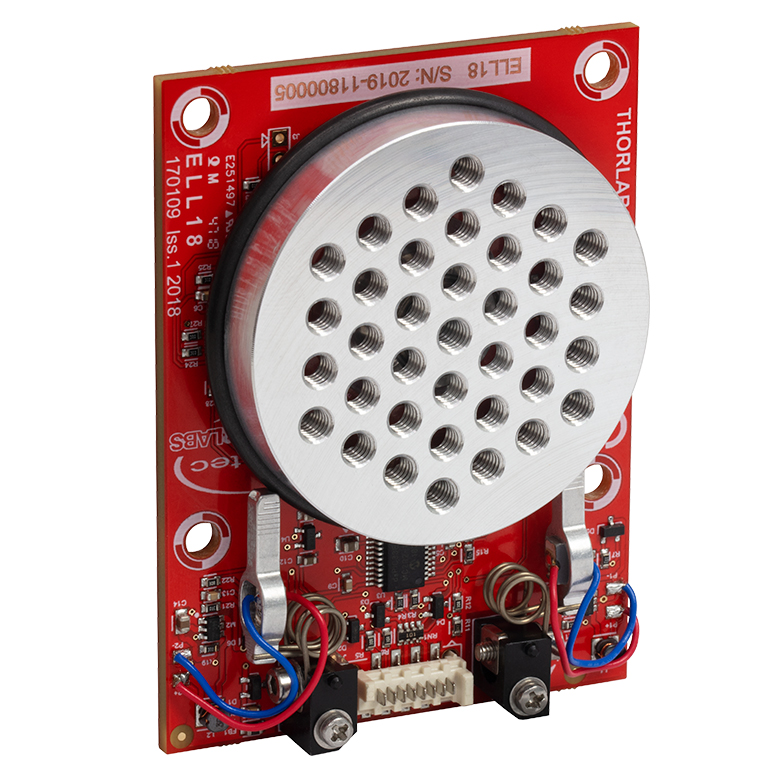 |
| Features | Tapped Mounting Platform for Mounting Prisms or Other Optics | Tapped Mounting Platform, Open Frame Design for OEM Applications |
| Additional Details | ||

 ズーム
ズーム
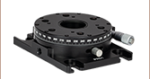
- 360°連続回転
- 2°単位のレーザ刻印目盛と補助線付き
- 取付けプラットフォーム高:17.0 mm
- 取付けプラットフォーム上のタップ穴:M3とM6
- 耐荷重:水平取付け時18 kg
- 光学テーブルまたはブレッドボードへの取付け用にM6貫通穴が4つ
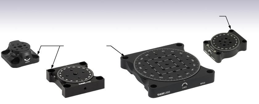
手動回転ステージRP005/Mの回転プラットフォームの大きさはØ25.4 mmで、滑らかでバックラッシュのない回転を必要とする比較的小さなオプトメカニクス部品用に適しています。ステージは360°連続回転し、回転プラットフォームの側面に沿って2°単位の目盛が刻印されています。また目盛には30°ごとに角度が表示されています。回転は側面の止めネジ(セットスクリュ)を2.0 mmボール(六角)ドライバまたは六角レンチで締め付けることによりロックできます。このロック用止めネジはステージから取り外さないようご注意ください。取り外すと固定する性能が恒久的に劣化する可能性があります。
回転プラットフォームにはM3タップ穴が6つあり、それらを用いてケージキューブ付き光学マウントやミニシリーズポストなどの比較的小さな部品を取り付けます。中央のM6タップ穴には、Ø12 mm~Ø12. 7 mm(Ø1/2インチ)やØ25 mm~Ø25.4 mm(Ø1インチ)のポストアセンブリなど、比較的大きな部品を取り付けます。また、上部プラットフォームにはØ3.2 mmの穴が2つ付いており、当社のFiberBench用の光学マウント、波長板モジュール、偏光モジュール、アライメントツールなどを取り付けることができます。それらのFiberBench用のアクセサリは、回転プラットフォーム側面にある1.5 mm六角止めネジで固定します。
ベース部分には、ステージを光学テーブルまたはブレッドボードに取り付けるためのM6貫通穴が4つ付いています。水平に取り付ける場合の最大耐荷重は18 kgです。

 ズーム
ズーム
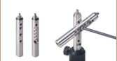
- 360°連続回転
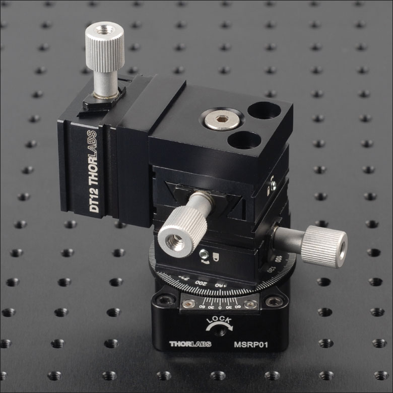
- 2°単位のレーザ刻印目盛と20 arcminのバーニャ目盛付き
- 取付けプラットフォーム高:13.0 mm
- 取付けプラットフォーム上のタップ穴:M3とM4
- 耐荷重
- 水平取付け時22 kg
- 水平方向の最大トルク1.3 N·m
- 光学テーブルまたはブレッドボードへの取付け用にM3貫通穴が4つ
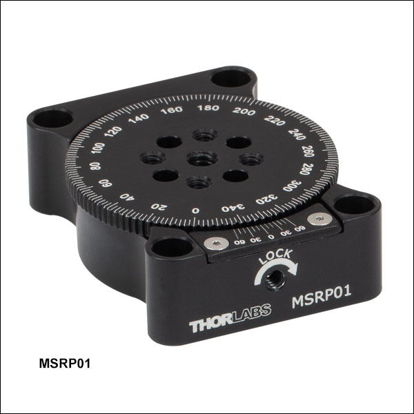
手動ミニシリーズの回転ステージMSRP01/Mの回転プラットフォームの大きさはØ35.6 mmで、2つの精密ベアリングを使用してより滑らかでバックラッシュのない回転を実現しています。ステージは360°連続回転し、回転プラットフォームの外周に沿って2°単位の目盛が刻印されています。目盛には20°ごとにその角度が表示されています。また20 arcminのバーニャ目盛も付いています。回転は側面の止めネジ(セットスクリュ)を1.3 mmボール(六角)ドライバまたは六角レンチで締め付けることによりロックできます。
回転プラットフォーム上にはM3タップ穴が4つと、中央にM4タップ穴が1つ付いており、ミニシリーズのポストやアクセサリ、あるいは上の写真のように小型アリ溝式ステージなどが取り付けられます。
ベース部分には、ステージをミニシリーズ光学ブレッドボードに取り付けるためのM3貫通穴が4つ付いています。側面のM3取付け穴はステージを垂直に取り付けるときに使用します。垂直に取り付ける場合の最大トルクは1.3 N·mです。水平に取り付ける場合の最大耐荷重は22 kgです。

 ズーム
ズーム
- 360°連続回転
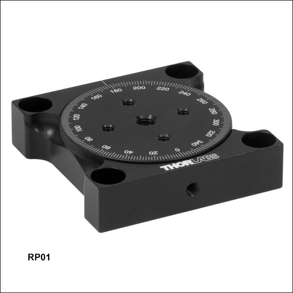
- 2°単位のレーザ刻印目盛と補助線付き
- 取付けプラットフォーム高:16.1 mm
- 取付けプラットフォーム上のタップ穴:M4とM6
- 耐荷重
- 水平取付け時50 kg
- 垂直取付け時4 kg
- 光学テーブルまたはブレッドボードへの取付け用にM6貫通穴が4つ
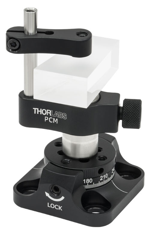
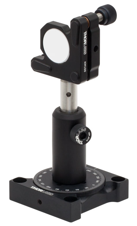
手動回転ステージRP01/Mの回転プラットフォームの大きさはØ52.8 mmで、滑らかでバックラッシュのない回転を必要とする比較的大きなオプトメカニクス部品用に適しています。ステージは360°連続回転し、回転プラットフォームの外周に沿って2°単位の目盛が刻印されています。また目盛には20°ごとにその角度が表示されています。回転は側面の止めネジ(セットスクリュ)を2.0 mmボール(六角)ドライバまたは六角レンチで締め付けることによりロックできます。
回転プラットフォーム上には4つのM4タップ穴と、中央に1つのM6タップ穴があります。M6タップ穴はØ12 mm~Ø12. 7 mm(Ø1/2インチ)やØ25 mm~Ø25.4 mm(Ø1インチ)のポストアセンブリ、あるいはオプトメカニクスマウントなど、右の写真のような比較的大きなアセンブリの取付けに使用します。
ベース部分には、ステージを光学テーブルまたはブレッドボードに取り付けるためのM6貫通穴が4つ付いています。側面のM4取付け穴はステージを垂直に取り付けるときに使用します。垂直に取り付ける場合の最大耐荷重は4 kgです。水平に取り付ける場合の最大耐荷重は50 kgです。

 ズーム
ズーム
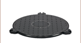
- 360°連続回転
- 1°単位のレーザ刻印目盛と補助線付き
- プラットフォーム高:17.8 mm
- プラットフォーム上のタップ穴
- RP03/M: M4、M6
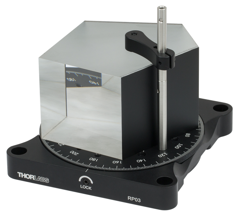
- 耐荷重
- 水平取付け時79 kg
- 垂直取付け時22 kg
- 光学テーブルまたはブレッドボードへの取付け用にM6貫通穴が4つ
手動回転ステージRP03/Mの回転プラットフォームの大きさはØ109.2 mmで、滑らかでバックラッシュのない回転を必要とする比較的大きなオプトメカニクス部品用に適しています。ステージは360°連続回転し、回転プラットフォームの外周に沿って1°単位の目盛が刻印されています。また目盛には20°ごとに角度表示されています。回転は側面の止めネジ(セットスクリュ)を2.0 mmボール(六角)ドライバまたは六角レンチで締め付けることによりロックできます。
回転プラットフォームRP03/M上のタップ穴は、M4が24個、M6が13個です。M4タップ穴はクランプアームPM3/MおよびPM4/Mに対応しています。これらのタップ穴を使用して、回転プラットフォームに小型の部品から大型の部品まで固定することができます。M4およびM6タップ穴は、手動式または電動式の移動ステージやポストアセンブリなどの大型システムを固定する際に使用できます。
ベース部分には、ステージを光学テーブルまたはブレッドボードに取り付けるためのM6用貫通穴が4つ付いています。側面にある3つのM4取付け穴はステージを垂直に取り付けるときに使用します。垂直に取り付ける場合の最大耐荷重は22 kgです。水平に取り付ける場合の最大耐荷重は79 kgです。