 Products Home
校正済みフォトダイオード
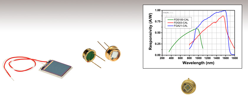
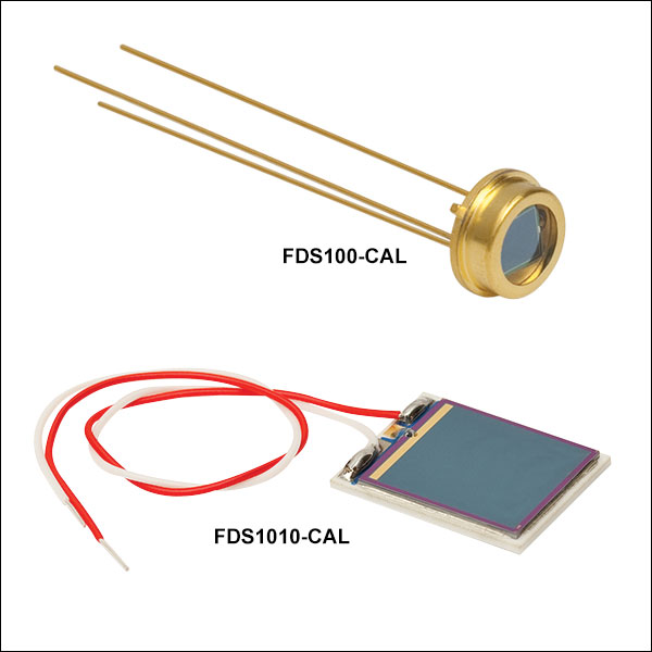
- Si, Ge, and InGaAs Photodiodes Available
- NIST Traceable
- Photodiodes Shipped with Calibration Curves
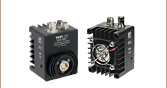
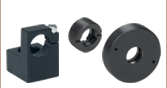
FDS1010-CAL
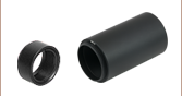
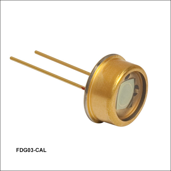
FDG03-CAL
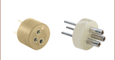
FGA21-CAL


Please Wait
| Mounted and Unmounted Detectors |
|---|
| Photodiodes |
| Mounted Photodiodes (200 - 1800 nm) |
| Unmounted Photodiodes (200 - 2600 nm) |
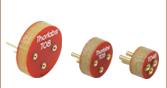
| Pigtailed Photodiodes (320 - 1000 nm) |
| Calibrated Photodiodes (350 - 1800 nm) |
| Photovoltaic Detectors (2000 - 10 600 nm) |
| Thermopile Detectors (190 - 20 000 nm) |
| Pyroelectric Detector (600 - 16 000 nm) |
Click to Enlarge
Figure 1.1 フォトダイオードFDS1010の応答感度特性
当社ではNISTトレーサブルな校正済みフォトダイオード4種類を在庫で取り揃えています。これらには、インジウムガリウムヒ素 (InGaAs)1種類、シリコン(Si)2種類、ゲルマニウム(Ge)1種類のフォトダイオードがございます。
校正の特長
- フォトダイオードのスペクトル範囲にわたり10 nmごとに感度を測定
- 測定不確定性:±5%
- NIST トレーサブル
各フォトダイオードには、データ表と感度特性VS波長のグラフが付属します。
フォトダイオードの感度特性はロットごとに異なります。そのため、ご購入いただいたフォトダイオードの感度特性がTable G1.1~G3.1,に記載されている値と若干異なる場合があります。Figure 1.1は、104個のフォトダイオードから得られた感度特性のバラツキの度合いを示しています。各データポイントで最小値(Minimum)、平均値(Average)および最大値(Maximum)を計算し、グラフ化しています。
ディテクタの検出部の端における不均一性は、フォトダイオードの出力の時間ドメイン応答を歪ませる不要な電気容量や抵抗作用を生じさせることにご注意ください。当社では入射光をフォトダイオードの検出部の中心へ正確に照射することを推奨いたします。これは、ディテクタ素子の前面に集光レンズやピンホールを設置することで可能となります。
こちらのフォトダイオードはゼロバイアスで校正されております。そのため、逆バイアスをかけてのご使用は推奨しておりません。逆バイアス電圧をかけると感度が上昇しますが、校正が無効になります。バイアス電圧やノイズフロアについての詳細は「実験データ」タブをご覧ください。
フォトダイオードのチュートリアル
動作原理
接合型フォトダイオードは、通常の信号ダイオードと似た動作をする部品ですが、接合半導体の空乏層が光を吸収すると、光電流を生成する性質があります。フォトダイオードは、高速なリニアデバイスで、高い量子効率を達成し、様々な用途で利用することが可能です。
入射光の強度に応じた、出力電流レベルと受光感度を正確に把握することが必要とされます。Figure 100Aは、接合型フォトダイオードのモデル図で、基本的な部品要素が図示されており、フォトダイオードの動作原理が説明されています。
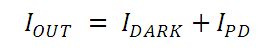
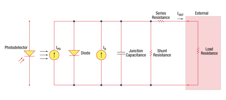
Figure 100A フォトダイオードの概略図
フォトダイオード関連用語
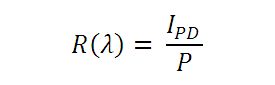
受光感度
フォトダイオードの受光感度は、規定の波長における、生成光電流 (IPD)と入射光パワー(P)の比であると定義できます。
Photoconductiveモード(光導電モード)とPhotovoltaicモード(光起電力モード)
フォトダイオードは、Photoconductiveモード(逆バイアス) またはPhotovoltaicモード(ゼロバイアス)で動作できます。 モードの選択は、使用用途で求められる速度と、許容される暗電流(漏れ電流)の量で決まります。
Photoconductiveモード(光導電モード)
Photoconductiveモードでは、逆バイアスが印加されますが、これが当社のDETシリーズディテクタの基本です。回路で測定できる電流量はフォトダイオードに照射される光の量を反映します。つまり、測定される出力電流は、入射される光パワーに対しリニアに比例します。逆バイアスを印加すると、空乏層を広げて反応領域が広くなるため、接合容量が小さくなり、良好な線形応答が得られます。このような動作条件下では、暗電流が大きくなりがちですが、フォトダイオードの種類を選ぶことで、暗電流を低減することもできます。(注:当社のDETディテクタは逆バイアスで、順方向バイアスでは動作できません。)
Photovoltaicモード(光起電力モード)
Photovoltaicモードでは、フォトダイオードはゼロバイアスで使用されます。デバイスからの電流の流れが制限されると電位が上昇します。このモードでは光起電力効果が引き起こされますが、これが太陽電池の基本です。Photovoltaicモードでは、暗電流は小さくなります。
暗電流
暗電流とは、フォトダイオードにバイアス電圧が付加されている時に流れる漏れ電流です。Photoconductiveモードで使用する場合に暗電流の値は高くなりがちで、温度の影響も受けます。 暗電流は、温度が10°C上昇するごとに約2倍となり、シャント抵抗は6°C の上昇に伴い倍になります。高いバイアスを付加すれば、接合容量は小さくなりますが、暗電流の量は増大してしまいます。
暗電流の量はフォトダイオードの材料や検出部の寸法によっても左右されます。ゲルマニウム製のデバイスでは暗電流は高くなり、それと比較するとシリコン製のデバイスは一般的には低い暗電流となります。Table 100Bではいくつかのフォトダイオードに使用される材料の暗電流の量と共に、速度、感度とコストを比較しています。
| Table 100B Photodiode Materials | ||||
|---|---|---|---|---|
| Material | Dark Current | Speed | Spectral Range | Cost |
| Silicon (Si) | Low | High Speed | Visible to NIR | Low |
| Black Silicon (B-Si) | Low | Medium Speeda | Visible to NIR | Moderate |
| Germanium (Ge) | High | Low Speed | NIR | Low |
| Indium Gallium Arsenide (InGaAs) | Low | High Speed | NIR | Moderate |
| Indium Arsenide Antimonide (InAsSb) | High | Low Speed | NIR to MIR | High |
| Extended Range Indium Gallium Arsenide (InGaAs) | High | High Speed | NIR | High |
| Mercury Cadmium Telluride (MCT, HgCdTe) | High | Low Speed | NIR to MIR | High |
接合容量
接合容量(Cj)は、フォトダイオードの帯域幅と応答特性に大きな影響を与えるので、フォトダイオードの重要な特性となります。ダイオードの面積が大きいと、接合容量が大きくなり、電荷容量は大きくなります。逆バイアスの用途では、接合部の空乏層が大きくなるので、接合容量が小さくなり、応答速度が速くなります。
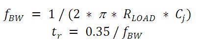
帯域幅と応答性
負荷抵抗とフォトディテクタの接合容量により帯域幅が制限されます。最善の周波数応答を得るには、50 Ωの終端装置を50 Ωの同軸ケーブルと併用します。接合容量(Cj)と負荷抵抗値(RLOAD)により、帯域幅(fBW)と立ち上がり時間応答(tr)の概算値が得られます。
雑音等価電力
雑音等価電力(NEP:Noise Equivalent Power)とは、出力帯域幅1 Hzでの信号対雑音比(SNR)が1になる入力信号のパワーです。NEPによって、ディテクタが低レベルの光を検知する能力を知ることができるので、この数値は便利です。一般には、NEPはディテクタの検出部の面積増加に伴って大きくなり、下記の数式で求めることができます。
この数式において、S/Nは信号対雑音比、Δf はノイズの帯域幅で、入射エネルギ単位はW/cm2となっています。詳細は、当社のホワイトペーパー「NEP – Noise Equivalent Power」をご覧ください。
終端抵抗
オシロスコープでの測定を可能にするためには、生成された光電流を電圧(VOUT)に変換する必要がありますが、負荷抵抗を用いて電圧変換します。
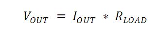
フォトダイオードの種類によっては、負荷抵抗が応答速度に影響を与える場合があります。最大帯域幅を得るには、50 Ωの同軸ケーブルを使用して、ケーブルの反対側の終端部で50 Ωの終端抵抗器の使用を推奨しています。このようにすることで、ケーブルの特性インピーダンスとマッチングできて共鳴が最小化できます。帯域幅が重要ではない特性の場合は、RLOADを増大させることで、所定の光レベルに対して電圧を大きくすることができます。終端部が不整合の場合、同軸ケーブルの長さが応答特性に対して大きな影響を与えます。したがってケーブルはできるだけ短くしておくことが推奨されます。
シャント抵抗
シャント抵抗は、ゼロバイアスフォトダイオード接合の抵抗を表します。理想的なフォトダイオードでは、シャント抵抗は無限大となりますが、実際の数値はフォトダイオードの材料の種類によって、10Ωのレベルから 数千MΩの範囲となる場合があります。例えばInGaAsディテクタのシャント抵抗は、10 MΩのレベルですが、GeディテクタはkΩのレベルです。このことは、フォトダイオードのノイズ電流に大きく影響を与える可能性があります。しかしながらほとんどの用途では、ある程度高い抵抗値であればその影響は小さく、無視できる程度です。
直列抵抗
直列抵抗は半導体材料の抵抗値で、この低い抵抗値は、通常は無視できる程度です。直列抵抗は、フォトダイオードの接触接続部とワイヤ接続部で発生し、ゼロバイアスの条件下でのフォトダイオードのリニアリティの主な決定要因になります。
一般的な動作回路
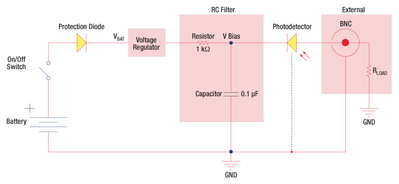
Figure 100C 逆バイアス回路(DETシリーズディテクタ)
Figure 100Cの回路はDETシリーズのディテクタをモデル化したものです。ディテクタは、入射光に対して線形の応答を得るために逆バイアス状態になっています。ここで生成された光電流の量は、入射光と波長に依存し、負荷抵抗を出力端子に接続すると、オシロスコープでモニタリングできます。RCフィルタの機能は、出力に雑音を載せてしまう可能性のある供給電力からの高周波雑音のフィルタリングです。

Figure 100D 増幅ディテクタ回路
高利得用途でアンプとともにフォトディテクタを使用できます。動作時には、PhotovoltaicモードまたはPhotoconductiveモードのいずれも選択可能です。このアクティブ回路はいくつかの利点があります。
- Photovoltaicモード:オペアンプで、点Aと点Bの電位が同じに維持されているので、フォトダイオードでは回路全体では0 Vに保たれています。このことで暗電流は発生しなくなります。
- Photoconductiveモード: フォトダイオードは逆バイアス状態であるので、接合容量を低下させ、帯域幅の状態を改善します。ディテクタの利得は、フィードバック素子(Rf)に依存します。ディテクタの帯域幅は、下記の数式で計算することができます。
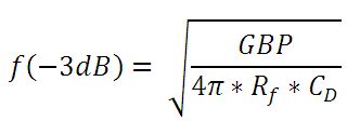
GBPが利得帯域幅積で、CDは接合容量と増幅器の静電容量の和です。
チョッパ入力周波数の影響
光導電信号は時定数の応答限界までは一定となりますが、PbS、 PbSe、HgCdTe (MCT)、InAsSbなどのディテクタにおいては、1/fゆらぎ(チョッパ入力周波数が大きいほどゆらぎは小さくなる)を持つため、低い周波数の入力の場合は影響が大きくなります。
低いチョッパ入力周波数の場合は、ディテクタの受光感度は小さくなります。周波数応答や検出性能は下記の条件の場合において最大となります。
![]()
概要
こちらのタブでは当社が提供するフォトダイオードの性能に関して実施した実験をまとめています。それぞれのセクションごとに独立した実験について記載しており、下の各ボックスをクリックするとご覧いただけます。「フォトダイオードの飽和限界とノイズフロア」では、温度、抵抗率、逆バイアス電圧、応答特性、システムの帯域幅などがフォトダイオードの出力ノイズに与える影響を調べています。「 フォトダイオードの感度均一性」では、フォトダイオードの受光面全体をビーム径の小さな光で走査し、感度の変化を調べています。素材構成の異なるフォトダイオードについての試験を行ったほかに、ユニットごとのバラツキを調べるためにシリコン(si)ベースの1種類のモデルの8ユニットについても試験をして比較しています。「暗電流の温度特性」および「ノイズ等価パワー(NEP)の温度特性」では、暗電流およびNEPがそれぞれ温度によってどのように変化するか、そしてそれが測定結果にどのような影響を与えるかを記述しています。「ビームサイズとフォトダイオードの飽和」では、フォトダイオードの飽和点が入射光のビームサイズによってどのように変化するかを示し、それらの結果を説明するために複数の理論モデルについて調べています。「バイアス電圧」では、入射光パワーがフォトダイオードの電子回路における有効逆バイアス電圧に与える影響を調べ、その変化を予測するモデルの信頼性を検証しています。
フォトダイオードの飽和限界とノイズフロア
ここでは当社のシリコンフォトダイオードの飽和限界とノイズフロアの測定結果をご紹介しています。フォトダイオードはすべて同じように機能しますが、フォトダイオードのノイズフロアと飽和限界はセンサ温度、抵抗率、逆バイアス電圧、応答特性、そしてシステムの帯域幅など多くのパラメータの影響を受けます。この実験ではシリコンフォトダイオード光検出システムにおける逆バイアス電圧と負荷抵抗の影響について調べました。逆バイアスの増加により飽和限界値は上がりましたが、ノイズフロアへの影響はわずかでした。負荷抵抗を小さくするとノイズフロアは測定システムのノイズレベルまで下がりましたが、飽和限界値も下がりました。これらの結果は逆バイアス電圧および負荷抵抗を選択する上で考慮すべき点を示しており、また、検出システムを構成する際にはすべての部品から生じるノイズを考慮すべきであることを示しています。
実験にはシリコンフォトダイオードFDS100を使用しました。光源には光パワーが0~50 mWのファイバーピグテール付き半導体レーザからのコリメート光を使用しています。コリメート光はまずビームスプリッタに入射しますが、大部分の光は透過して試験対象のフォトダイオードに入射するようにし、反射された残りの光は参照用のパワーセンサに入射しました。この状態で負荷抵抗と逆バイアス電圧を様々に変化させ、フォトダイオードの応答特性を評価しました。

Figure 171A~171Dでは、様々なテストに対する測定結果をまとめています。これらのグラフにより、様々な逆バイアス電圧ならびに負荷抵抗下でのフォトダイオードの線形応答性、ノイズフロア、そして飽和限界の変化がご覧いただけます。Figure 171Aは5 Vの逆バイアス電圧ならびに10 kΩの負荷抵抗におけるフォトダイオードの応答特性です。出力電圧が逆バイアス電圧に近づくと、フォトダイオードの応答は上限値で飽和します。応答の下限値であるノイズフロアは、暗電流ならびに負荷抵抗の熱雑音(ジョンソンノイズ)によるものです。Figure 171Bは、1 kΩの負荷抵抗のもとで逆バイアス電圧を様々に変えた時のフォトダイオード出力の測定結果をまとめています。逆バイアス電圧を(仕様値内で)増加させると飽和限界値が上がることを示しています。Figure 171Cでは5 Vの逆バイアス電圧のもとで様々に負荷抵抗値を変えたときのフォトダイオード出力電圧の測定結果です。負荷抵抗を増やすと、電圧応答の傾斜が急峻になることを示しています。Figure 171Dでは0 Vの逆バイアス電圧のもとで、負荷抵抗値を様々に変えたときのノイズフロアの測定結果をまとめています。負荷抵抗が大きくなるとノイズフロアも上昇します。なお、1 kΩのデータでは、測定システム内の電圧ノイズによりジョンソンノイズの理論値以上の値が測定されました。5 Vの逆バイアス電圧でのノイズフロアの変化は全体的に僅かでした。この実験に使用された装置や実験結果のまとめはこちらをクリックしてご覧ください。
Click to Enlarge
Figure 171B 出力電圧の逆バイアス電圧依存性
Click to Enlarge
Figure 171D 様々な負荷抵抗における応答特性
Click to Enlarge
Figure 171C 様々な負荷抵抗におけるノイズフロア
フォトダイオードの感度均一性
 Click to Enlarge
Figure 171E 感度はフォトディテクタから出力される光電流の大きさと入射光パワーとの関係を示し、入射光の波長に依存します。
フォトダイオードの感度は受光面全体で均一か?
フォトディテクタからの出力信号の大きさは、入射光のパワーと波長に依存します。感度は出力信号と入射光パワーの関係を表し、その大きさは出力される光電流を入射光パワーで割った値になります。感度の単位はamps/wattですが、その値は波長によっても変化します。しかし、フォトダイオードの受光面内のどの部分に光が入射するかで感度が変化することは、しばしば見過ごされがちです。
この実験では、フォトダイオードの受光面よりも小さいビーム径の光で受光面全体を走査し、フォトディテクタの感度の変化を調べました。試験したフォトディテクタは、ガリウムリン(GaP)、シリコン(Si)、インジウムガリウムヒ素(InGaAs)、ゲルマニウム(Ge)のマウント済みフォトダイオードです。
感度の波長依存性1,2
感度が波長によって変化する一つの理由は、光パワー、波長、および光生成電子の関係性にあります。受光面に光ビームが入射したとき、ビーム内のエネルギを光の入射時間で割った値に等しい光パワーがディテクタに供給されます。単一波長のビームのエネルギは、入射する光子数に単一光子のエネルギを掛けた値と等しくなります。光の波長が短くなると光子のエネルギは大きくなります。もし波長が短くなっても光パワーが同じならば、入射する光子数が減少したことを意味します。
フォトディテクタ内では、単一光子からは単一の電子しか生成できません。そのため、光パワーを一定に保ったまま入射光の波長を短くすると光電流は減少します。感度は単位時間あたりの入射光子数ではなく、入射光パワーに対して出力される光電流の大きさを表すため、波長が短いと感度は低くなります。Figure 171Eの感度曲線は、波長が長くなると感度が大きくなる様子を表している例です。
長波長側におけるフォトディテクタの感度は、半導体材料固有の特性によって制限されます。入射光子が光電流に寄与するには、光子は電子をホスト原子との結合から解放するのに十分なエネルギを持っている必要があります。長波長側の限界を超えた波長域では、光子のエネルギは電子を解放するのに十分ではなくなります。この限界の波長はフォトダイオードを構成する半導体材料によって決まります。
フォトダイオード受光面内の感度分布1,2
光子のエネルギを吸収してホスト原子との結合から解放された電子は、光生成電子となります。光生成電子は、電子が生成された場所から半導体材料を通過して電極との接続部まで移動した場合にのみ光電流に寄与します。光生成電子がその接続部に到達する前に半導体材料に再吸収されてしまうと、光電流には寄与しません。その可能性は半導体材料内に欠陥がある場合に大きくなります。
欠陥とは半導体の結晶格子が不完全な部分のことで、結晶格子内の転位、不純物、ボイドなどが含まれます。また、実際の結晶は大きさが有限であり、その表面も欠陥になります。完全結晶であるためには長さ、高さ、幅ともに無限である必要があります。半導体結晶内の欠陥では光生成電子は高い確率で吸収され、電子は光電流に寄与することなく、そのエネルギは熱に変えられてしまいます。
欠陥付近に発生した光生成電子は再吸収されやすく、従って光電流には寄与しにくくなります。半導体内の欠陥密度を小さくすることはできますが、フォトダイオードに使用されている半導体結晶は完全ではありません。欠陥密度が半導体結晶の体積内で一様でないことや、ある種の半導体材料の結晶成長では他の材料よりも多くの欠陥が生じやすいといったことは珍しいことではありません。
もし半導体材料の体積内での欠陥密度が一様でなければ、各領域で発生する光電流の大きさは異なると考えられます。フォトディテクタの感度は光電流の大きさに依存するため、フォトディテクタに入射する光の位置を変えたときに、欠陥密度の変化に伴って感度も変わることになります。この影響を以下の方法で調べました。
Click to Enlarge
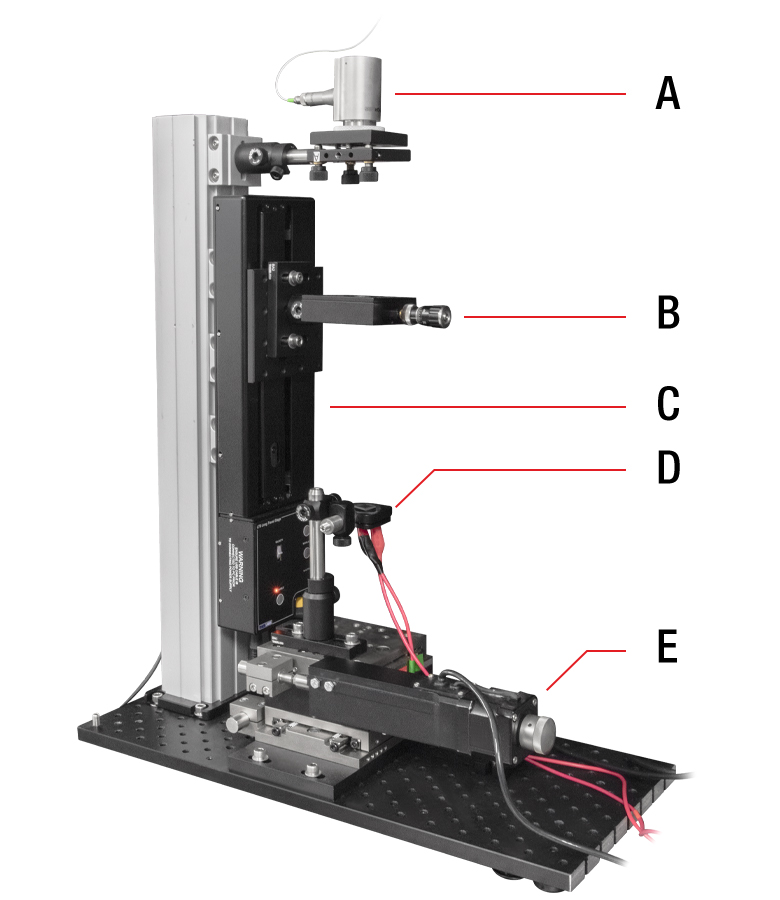
Figure 171F フォトダイオード受光面における感度の変化を測定するためのセットアップ。写真に見えるコンポーネントは以下の通りです:(A)反射型コリメータ、(B)アクロマティック複レンズ、(C)垂直方向に取り付けられた直線移動ステージ、(D)試験対象のフォトディテクタ、 (E)2台の水平移動ステージ
実験セットアップと実験結果
測定の目的
複数のフォトディテクタに対して、受光面における感度の均一性を調べるための試験を行いました。GaP(1台)、Si(4台)、InGaAs(2台)、Ge(2台)をベースにしたフォトディテクタの感度均一性を、波長を選択して測定しました。試験内容は以下の通りです。
- 9台のフォトディテクタを全てピーク感度に近い波長で試験 (結果はTable 171Gを展開するとご覧いただけます)
- Si、InGaAs、Geをベースにしたフォトディテクタを3種類の波長で試験 (結果はTable 171Hを展開するとご覧いただけます)
- 8台のSiをベースにしたフォトディテクタをピーク感度に近い波長で試験 (結果はTable 171Jを展開するとご覧いただけます)
実験セットアップ(文中の記号はFigure 171Fに示すコンポーネントの記号に対応)
この実験セットアップでは、まず光源(写真には表示されていません)と、キネマティックマウントKM100Tに取り付けられたコリメータRC12APC-P01(A)とをファイバで結合しています。次に、マウントST1XY-D(/M)内に取り付けられた焦点距離150 mmのアクロマティック複レンズAC254-150-A(B)を用いて、光をフォトディテクタ(D)の受光面上に集光します。フォトディテクタは磁気接合式の脱着式キャリッジセットKB1P(/M)を用いて取り付けられています。 垂直アーム内の他のコンポーネントとして、電動式直線移動ステージLTS150(/M)(旧製品)(C)、垂直取付けプレートXT66P1、66 mmコンストラクションレールXT66-500、および4つのクランププラットフォームXT66C4が用いられています。水平アーム内のコンポーネントとしては、2つの電動式直線移動ステージLNR50S(/M)(旧製品)(E)、XYアダプタープレートLNR50P3(/M)、ベースプレート1つ、およびフォトディテクタ(D)の受光面上でビームを走査するための2つの閉ループステッピングモーターコントローラBSC201(写真には表示されていません)が用いられています。 ほとんどの光源は当社のスーパールミネッセントダイオードシリーズを使用しています。405 nm光源のみ例外で、ベンチトップ型レーザ光源S3FC405を使用しています。
手順
ビーム径はフォトディテクタの受光面積に合わせて調整し、各フォトダイオードの受光面を60 x 60のグリッドに分割して約3600箇所で測定しました。各フォトダイオードに入射したビーム径は50 µm~500 µmで、個々の測定で使用したビーム径についてはTable 171G、171H、171Jを展開し、プロット図の説明をご覧ください。説明は対象のプロット図をクリックするとご覧いいただけます。
受光面を走査するとき、ビームは静止しています。これに対してフォトディテクタは、2台の電動ステージLNR50S(/M)により光軸に対して垂直な2方向に移動します。フォトディテクタの全ての受光面を試験するため、走査面の面積は受光面よりも大きくしました。
この試験では、フォトダイオードに対して逆バイアス電圧は印加していません。
結果(Table 171G、171H、171JのMore [+]をクリックすると表が展開され、Less [-]をクリックすると閉じます。)
測定データは規格化され、測定位置ごとにプロットされています。各データは受光面中心での測定値で規格化し、各フォトディテクタの受光面の感度分布を示すプロット図にしています。これにより9種類のフォトディテクタの測定結果を比較できます。ノイズと区別がつかないデータポイントは削除するように処理しています。この処理は各フォトディテクタの受光面外の測定データを削除するのにも適用しています。ただし、この方法では受光面のエッジ、あるいはその近傍の測定値も削除してしまうことがあります。このような領域からの光電流が小さい原因としては、ビームスポットの一部が受光面の外側の領域にあたっていること、エッジ付近における欠陥の密度が高いために光電流が抑制されていることなどが考えられます。
プロット図はTable 171G、171H、171Jを展開してご覧いただけます。各プロット図の点線は、フォトダイオード受光面の中心部の面積90%を占める部分を表しています。一般的な用途では、エッジの影響を避けるためにビームは中心部の90%の領域内に入射するようにしてください。各プロット図をクリックするとフォトダイオードの受光面積や走査に使用したビームサイズについての情報が表示されます。
この試験ではフォトダイオードのサンプルサイズ数が少ないため、これらの測定値は同型のフォトディテクタの代表値ではありますが、同じ型番でも製品ごとに測定結果は異なります。これらのフォトダイオードについて得られた測定結果は繰り返し得ることができます、半導体結晶は個体ごとに異なるため測定結果は製品ごとに異なります。以下に3つの表を掲載しています。
- Table 171G:受光面内の感度の変化量は、GeおよびGaPをベースにしたフォトディテクタの方が、SiおよびInGaAsをベースにしたフォトディテクタに比べて大きくなっています。このことは、SiおよびInGaAsをベースにした半導体材料の方が、GeおよびInGaAsをベースにした半導体材料よりも、欠陥密度が均一であることを示しています。
- Table 171H:Si、InGaAsおよびGeをベースにしたフォトディテクタの受光面内の感度の変化量は波長によって異なります。各フォトディテクタのこの感度の変化量は、ピーク感度の波長値付近で最小になります。
- Table 171J:Siベースの8台の同型フォトディテクタは、受光面内の感度均一性が同様であることを示しています。
| Table 171G 9台のフォトディテクタ:ピーク感度付近の波長に対する感度の均一性 |
|---|
| 測定したフォトディテクタ | 記載された波長における受光面の感度分布 | 分光感度特性のグラフ(典型値) | |
| GaP-Based Photodetector SM05PD7A: Mounted Photodiode FGAP71 |  Click for Details |  Click to Enlarge | |
| Si-Based Photodetectors SM05PD2A: Mounted Photodiode FDS010 and SM1PD2A |  Click for Details |  Click for Details |  Click to Enlarge Click to Enlarge |
| Si-Based Photodetectors SM05PD1A: Mounted Photodiode FDS100 and SM1PD1A: Mounted Photodiode FDS1010 |  Click for Details |  Click for Details |  Click to Enlarge Click to Enlarge |
| InGaAs-Based Photodetectors SM05PD5A: Mounted Photodiode FGA21 and SM05PD4A: Mounted Photodiode FGA10 |  Click for Details |  Click for Details |  Click to Enlarge Click to Enlarge |
| Ge-Based Photodetectors SM05PD6A: Mounted Photodiode FDG1010 and SM1PD5A: Mounted Photodiode FDG03 |  Click for Details |  Click for Details |  Click to Enlarge Click to Enlarge |
| Table 171H Si、InGaAs、Geをベースにしたフォトディテクタ:3種類の波長における感度均一性 |
|---|
| フォトディテクタ | 記載された波長における受光面の感度分布 | 分光感度特性のグラフ(典型値) | ||
| Si-Based Photodetector SM1PD1A: Mounted Photodiode FDS1010 |  Click for Details Click for Details | Click for Details |  Click for Details Click for Details |  Click to Enlarge Click to Enlarge |
| InGaAs-Based Photodetector SM05PD5A: Mounted Photodiode FGA21 |  Click for Details Click for Details |  Click for Details Click for Details | Click for Details |  Click to Enlarge Click to Enlarge |
| Ge-Based Photodetector SM1PD5A: Mounted Photodiode FDG1010 |  Click for Details Click for Details |  Click for Details Click for Details | Click for Details |  Click to Enlarge Click to Enlarge |
| Table 171J Siベースの8台のフォトディテクタSM1PD2A:ピーク感度付近の波長に対する感度均一性の比較 |
|---|
| 受光面の感度均一性に関する製品ごとの差異を比較するために、8台のSiベースのフォトディテクタSM1PD2Aについて測定しました。ピーク感度付近の波長である830 nmの光を用いて測定しました(右のグラフ参照)。 |  Click to Enlarge | ||
 Click for Details |  Click for Details |  Click for Details |  Click for Details |
 Click for Details |  Click for Details |  Click for Details |  Click for Details |
参考文献
[1] G. P. Agrawal, Fiber-Optic Communication Systems, 2nd ed., John Wiley & Sons, Inc., New York, 1997. (Particularly Chapter 4)
[2] A. Rogalski, K. Adamiec, and J. Rutkowski, Narrow-Gap Semiconductor Photodiodes, SPIE Press, Bellingham, WA, 2000.
暗電流の温度特性
いくつかのマウント無しディテクタについて、暗電流の温度特性を測定しました。暗電流とは、下記に説明するように光が入射されていないときのpn接合型フォトディテクタに流れる比較的小さい電流です。ここでは、シリコン(Si)、ゲルマニウム(Ge)、ガリウムリン(GaP)、そしてインジウムガリウムヒ素(InGaAs)の逆バイアス型フォトダイオードについて、25 °C~約55 °Cの温度範囲で測定しました。
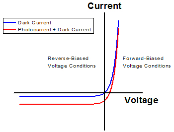
Figure 171K pn接合型フォトダイオードの電流-電圧特性
pn接合型フォトダイオードの電流-電圧特性
pn接合型フォトダイオードの電流-電圧特性は、Figure 171Kに示すように順方向バイアスと逆方向バイアスの電圧でそれぞれ特徴があります。pn接合フォトダイオードに逆バイアス電圧をかけた場合、ダイオードにかかる電位差は電流の流れる方向に対して逆方向になります。 逆バイアス型フォトダイオードに対して光が入射していないときには、電流が流れないのが理想です。
しかし実際にはフォトダイオードの半導体材料内部でのランダムプロセスにより、常に電流キャリア(電子と正孔)が生成され、それにより電流が発生します。このような電流の発生プロセスは、電子と正孔の光生成によるものではありません。それらの多くは半導体材料内部の熱エネルギによって発生します[1]。この暗電流は一般的には小さいですが、フォトダイオードに逆バイアスをかけたときには光が照射されていなくても存在します。暗電流の大きさはフォトダイオードの素材構成によって異なり、熱的な発生プロセスの効率はディテクタのセンサーヘッドに使用される半導体の種類と結晶品質に依存します。暗電流は、フォトダイオードの温度が上昇にするにつれて大きくなることが予測されます。
フォトダイオードに光が照射されると、入射光により発生した電流(光電流)が暗電流に重畳されます。光電流のキャリアは入射光子のエネルギによって生成されます。照射される光の強度がある閾値を超えると、光電流は暗電流よりも大きくなります。光電流が暗電流よりも大きい場合には、光電流の大きさは全電流を測定した後、暗電流を差し引くことによって求められます。一方、光電流が暗電流より小さい場合には、その検出は不可能です。そのため、フォトダイオードの暗電流は最小化するのが望ましいことになります。
フォトダイオードに逆電圧をかけたとき、便宜上、ここまで暗電流と光電流は電圧に依存しないものとして述べてきましたが、実際には完全に電圧に依存しないわけではありません。ダイオードに光が照射されているかどうかにかかわらず、逆バイアス電圧が上昇するにつれて電流は増加します。また、逆バイアス電圧がある閾値を超えるとフォトダイオードは降伏し、急激に大きい電流が流れてダイオードが恒久的に損傷する可能性があります。
実験:筐体付きフォトダイオードの暗電流の測定
4つの代表的なマウント無しディテクタ(SiディテクタFDS1010、GeディテクタFDG50、GaPディテクタFGAP71(旧製品)、InGaAsディテクタFGA10)について、その暗電流を25 °C~約55 °Cの温度範囲で測定しました。
Click to Enlarge
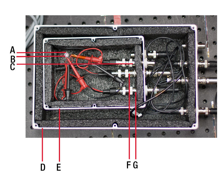
Figure 171L カバーを外し、FGA10を設置した入れ子式金属ボックスの試験冶具。
どちらの箱も内側は黒色の断熱材で覆われています。
A:サーミスタ、B: FGA10、C: BNC-BNCフィードスルー、D: 外側のボックス、E: 内側のボックス、F:BNC-Triaxフィードスルー、G:BNC-BNCフィードスルー
Click to Enlarge
Figure 171N ホイルヒータ、温度コントローラTED8040、そしヒータを流れる電流を制御する2つの整流ダイオードを含む電子回路(本文参照)。
実験のセットアップ
この実験セットアップでは、フォトダイオードに一定の逆バイアス電圧を供給することや、ディテクタの温度制御、ディテクタに対する遮光などに留意し、また測定電流が電波障害(EMI)の影響を受けないように外部と絶縁してディテクタとピコアンメータKeithley 6487を接続しました。ディテクタの暗電流はnAオーダの場合もあり、正確な測定のためにはこれらの条件を制御することが重要です。
ディテクタは2つの入れ子式アルミニウム製ボックスで囲っています(Figure 171Lはカバーを外した状態です)。1つのボックスのみでフォトダイオードを遮光することはできますが、実験ではEMIを遮断するために外側にもボックスを配置しています。ディテクタは内側のボックス内にあり、アンメータKeithley 6487と電気接続されています。ピコアンメータは5 Vの逆バイアスを供給し、出力電流信号を受信します。ピコアンメータとフォトダイオード間の電気信号は、複数のケーブルとフィードスルーを介して2つのボックスを通過します。5 Vのバイアス電圧は、2つの金属製ボックスの壁の中にある同軸ケーブルとBNC-BNCフィードスルーを介してフォトダイオードに接続されています。フォトダイオードからの電流信号ラインは、内側のボックスの壁の中に組み込まれているBNC-TriaxフィードスルーのBNC端子に接続されています。信号は外側のボックス内のTriaxおよびTriax-Triaxフィードスルーを通過し、ピコアンメータKeithley 6487に向かいます。同軸ケーブルは遮蔽性能が低く、それを使用してピコアンメータへ信号を送るときにはディテクタからの信号にEMI源からのノイズが混入する場合があるため、Triaxケーブルが使用されています。外側のボックスは内側のボックスをEMIから遮蔽するので、信号がディテクタからBNC-Triaxフィードスルーに移動する際に発生するノイズは低減されます。
実験中のフォトダイオードの温度は、サーミスタを用いて連続的にモニタしました。 サーミスタは熱伝導テープでFDG50、FGAP71、FGA10のTO Canに隙間なく固定されています。FDS1010のフォトセンサはセラミック製の基板に取り付けられています。実験の際、サーミスタは基板の裏側にテープで固定しました。サーミスタと温度ロガーTSP01間の電気的接続にはBNCケーブルを使用し、BNC-BNCバルクヘッドフィードスルーを通じて入れ子式ボックスの外へ信号を取り出し、カスタム仕様のBNC-フォノジャックケーブルを使用して温度ロガーに接続しました。
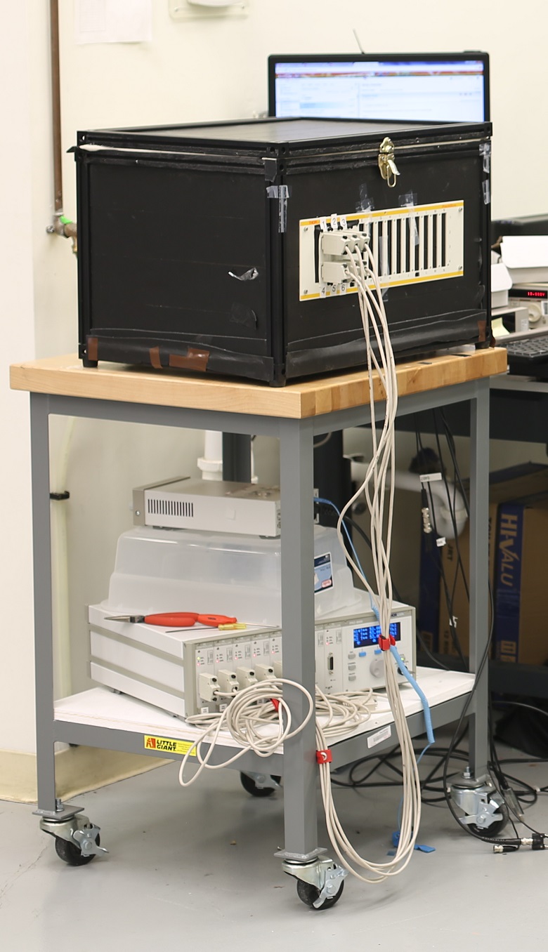
この試験には標準品の筐体XE25C9をベースにしたカスタム仕様の温度チャンバが使用されました。温度チャンバはFigure 171Mの上段に表示されています。筐体は底面と4つの壁を有し、内側と外側の全面に絶縁体が付いています。筐体の蓋はハードボードで作られており、XE25シリーズレールで縁取られています。ハードボードの内側には絶縁体が付いています。XE25C9の筐体の壁には6個のホイルヒータが装着され、6個の熱電冷却(TEC)コントローラTED8040を取り付けたPRO8000(Figure 171Mの下段に設置)によって作動します。TED8040はそれぞれヒータおよびチャンバ内に取り付けられたサーミスタに接続されています。サーミスタから読み取った値をもとにヒータ電流が決定されます。チャンバはアクティブには冷却されません。その代りにヒータを駆動する電流を止め、さらにオプションとしてチャンバの蓋を開けて冷却します。
TED8040ユニットはTECに接続可能です。電流をある方向に流すと熱が発生し、それと逆方向に流すと冷却されます。このため、筐体の温度が設定値を超えた場合、実験セットアップ内のTED8040ユニットは駆動電流を切断することはしません。その代りに電流を逆方向に流し、冷却を行います。これに対し、ホイルヒータは電流の流れる方向に関わらず熱を発生します。駆動電流をヒータから迂回させるために、2つの整流ダイオードを有する電子回路(Figure 171N参照)が設計・内蔵されています。整流ダイオードは電流を1方向にのみ流します。サーミスタに表示される温度が設定よりも低い場合、電流は赤い矢印の方向に流れてヒータを通過し、熱が発生します。筐体の温度が設定よりも高くなった場合、コントローラTED8040は電流の方向を逆向きにし、青い矢印の方向に流れるようにします。この状態では、回路内の電流はヒータの方向へは流れず、チャンバは冷却されます。
実験結果
Figure 171Pは、SiディテクタFDS1010、GeディテクタFDG50、GaPディテクタFGAP71、InGaAsディテクタFGA10で測定された暗電流のグラフです。データは、25 °C~55 °Cの温度下(Figure 171Qの青い領域)において連続して取得されました。Figure 171Qは実験中に測定されたフォトダイオードの温度変化の代表的な例です。フォトダイオードの温度プロファイルは、温度の上昇、その後徐々に最高温度への到達、そして温度の下降というように変化します。Figure 171Pで示されているデータは、25 °C~55 °Cの間で測定された全ての暗電流です。測定のタイミングは異なりますが、電流は同じ温度において測定されています。
Figure 171Pのデータ曲線は、測定された暗電流がフォトダイオードの構成材料によって異なることを示しています。暗電流値が低い順に:
- GaPディテクタFGAP71(暗電流値は最小)
- InGaAsディテクタFGA10
- SiディテクタFDS1010
- GeディテクタFDG50(暗電流値は最大)
最大値は最小値よりも6桁ほど大きくなっています。どのフォトダイオードも、温度が上昇すると暗電流も増加しています。グラフのひし形の点は25 °Cでの各ディテクタの暗電流の仕様値です。これらの点は25 °Cでの暗電流の最大値を示しています。各ダイオードは25 °Cではこの値よりも小さい値でなければなりませんが、25 °Cよりも高い温度ではこの仕様値よりも大きくなる場合があります。
Click to Enlarge
Figure 171Q チャンバ内の環境で制御された代表的なフォトダイオードの温度変化。
暗電流は25 °C~55 °C(青い領域)で測定し、その値はFigure 171Pにプロットしています。
実験結果についての制限事項
測定はディテクタの種類毎に1台を用いて実施しており、一般的な傾向を示すことを目的としております。よって特定のダイオードの仕様として捉えるものではありません。測定された暗電流はバイアス電圧や負荷抵抗の温度依存性、その他の様々な要因に影響されます。測定に対するそれらの影響を抑制するために、必要な5 Vの逆バイアスを供給するアンメータKeithley6487を使用するなどの工夫をしています。 アンメータを使用することにより、温度依存性があるかもしれない負荷抵抗器が不要になりました。サーミスタはできる限り半導体センサの近くに配置しましたが、直接センサには接触していません。そのため、測定温度と実際の半導体材料の温度に差があるかもしれません。暗電流は環境チャンバの温度を連続的に変化させて測定しました。この実験では湿度は制御されていません。
[1] J. Liu, Photonic Devices. Cambridge University Press, Cambridge, UK, 2005
ノイズ等価パワー(NEP)の温度特性
いくつかのマウント無しフォトディテクタについて、ノイズ等価パワー(NEP)温度特性を測定しました。下のセクションで説明しているように、NEPはフォトディテクタの最小感度を示す一般的な測定基準です。 ここでは、シリコン(Si)、ゲルマニウム(Ge)、ガリウムリン(GaP)、そしてインジウムガリウムヒ素(InGaAs)の逆バイアスされたフォトダイオードについて、25 °C~55 °Cの温度範囲で測定しました。
ノイズ等価パワー(NEP)
NEPの最も一般的な定義は、「1 Hzの出力帯域幅において信号対雑音比(SNR)が1となる入力信号のパワー」です。[1] 従って、NEPを求めるにはまず、フォトダイオードの最小ノイズを知る必要があります。光学信号をブロックしても、ディテクタ自体から発生したノイズはまだ存在します。フォトダイオードのノイズの主な原因としては、暗電流によるショットノイズとシャント抵抗による熱ノイズの2つがあります。
暗電流は、デバイスを流れる比較的小さな電流で、入射光がない状態でも存在します。暗電流についての詳細は「暗電流の温度特性」セクション内でご覧いただけます。ショットノイズは、電荷キャリアの量子化特性によって発生します。ディテクタに光が入射されていない場合は、公式を用いてディテクタの暗電流を算出することで決定できます。[2]
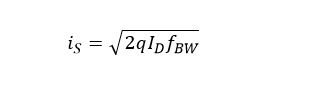
ここでisはショットノイズ、Idは暗電流、qは電荷、fBWは帯域幅です。帯域幅は別のフォトダイオードと比較できるように1 Hzに設定します。
熱ノイズつまりジョンソンノイズは、電荷キャリアのランダムな熱運動によるものです。熱ノイズは装置の抵抗素子によってのみ発生します。フォトダイオードディテクタの場合、シャント抵抗を考慮に入れる必要があります。シャント抵抗はゼロバイアスのフォトダイオードのpn接合における抵抗です。言い換えると、ゼロ電圧地点におけるIV特性カーブの傾きの逆数です。ゼロ点での勾配を正確に算出することは難しいため、V = ±10 mVにおける電流を測定して勾配を算出するという手法が業界で一般的に認められています。これにより、シャント抵抗による熱ノイズRSHは下記の式で表されます:
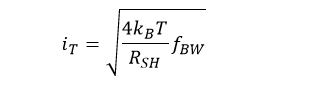
ここでitは熱ノイズ(電流として表されます)、kBはボルツマン定数、Tは温度、 RSHはシャント抵抗、fBWは帯域幅です。
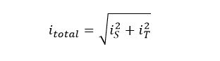
ノイズの総量itotalはすべてのノイズ源の和となります:
注:この結果は、フォトダイオードの出力電流で表されるノイズの総量です。それに対して、NEPは入射した光パワーとして表されます。したがって、NEPの仕様値を比較するには、仕様の波長範囲における感度(典型値)を使用します:

また、別のダイオードと比較する際に容易に計算できるよう、帯域幅を1 Hzに設定しました。
実験:暗電流およびシャント抵抗の測定
パッケージされていない状態の代表的な4つのフォトダイオードのNEPを、25~55 °Cにおいて測定しました。測定には以下のディテクタを使用しました:SiディテクタFDS1010、GeディテクタFDG50、GaPディテクタFGAP71(旧製品)、InGaAsディテクタFGA10。
Click to Enlarge
Figure 171R カバーを外し、FGA10を設置した入れ子式金属ボックスの試験冶具。
どちらの箱も内側は黒色の断熱材で覆われています。.
A: サーミスタ、B:FGA10、C:BNC-BNCフィードスルー、D:外側ボックス、E:内側ボックス、F:BNC-Triaxフィードスルー、G:BNC-BNCフィードスルー
Click to Enlarge
Figure 171U 電子回路内のホイルヒータ、温度コントローラTED8040、抵抗ヒータを通過する2つの整流ダイオードの制御電流(本文参照)。
実験のセットアップ
この実験セットアップでは、フォトダイオードに一定の逆バイアス電圧を供給することや、ディテクタの温度制御、ディテクタに対する遮光などに留意し、また測定電流が電波障害(EMI)の影響を受けないように外部と絶縁してディテクタとピコアンメータKeithley 6487を接続しました。ディテクタの暗電流はnAオーダの場合もあり、正確に測定するためにはこれらの条件を制御することが重要です。
ディテクタは2つの入れ子式アルミニウム製ボックスで囲っています(Figure 171Rカバーを外した状態です)。1つのボックスのみでフォトダイオードを遮光することはできますが、実験ではEMIを遮断するために外側にもボックスを配置しています。ディテクタは内側のボックス内にあり、ピコアンメータKeithley 6487と電気接続されています。ピコアンメータは逆バイアスを供給し、出力電流信号を受信します。ピコアンメータとフォトダイオード間の電気信号は、複数のケーブルとフィードスルーを介して2つのボックスを通過します。バイアス電圧は、2つの金属製ボックスの壁の中にある同軸ケーブルとBNC-BNCフィードスルーを介してフォトダイオードに接続されています。フォトダイオードからの電流信号ラインは、内側のボックスの壁の中に組み込まれているBNC-TriaxフィードスルーのBNC端子に接続されています。信号は外側のボックス内のTriaxおよびTriax-Triaxフィードスルーを通過し、ピコアンメータKeithley 6487に向かいます。同軸ケーブルは遮蔽性能が低く、それを使用してピコアンメータへ信号を送るときにはディテクタからの信号にEMI源からのノイズが混入する場合があるため、Triaxケーブルが使用されています。外側のボックスは内側のボックスをEMIから遮蔽するので、信号がディテクタからBNC-Triaxフィードスルーに移動する際に発生するノイズは低減されます。
暗電流を測定する場合、バイアス電圧は5 Vに設定します。シャント抵抗を算出するには、バイアス電圧を+10 mVおよび-10 mVに設定して電流を測定します。
実験中のフォトダイオードの温度は、サーミスタを用いて連続モニタしました。サーミスタは熱伝導テープでFDG50、FGAP71、FGA10のTO Canに隙間なく固定されています。FDS1010のフォトセンサはセラミック製の基板に取り付けられています。実験の際、サーミスタは基板の裏側にテープで固定しました。サーミスタと温度ロガーTSP01間の電気的接続にはBNCケーブルを使用し、BNC-BNCバルクヘッドフィードスルーで入れ子式ボックスの外へ信号を取り出し、カスタム仕様のBNC-フォノジャックケーブルを使用して温度ロガーに接続しました。
この試験には標準品の筐体XE25C9をベースにしたカスタム仕様の温度チャンバが使用されました。温度チャンバはFigure 171U中の上段に表示されています。筐体は底面と4つの壁を有し、内側と外側の全ての面に絶縁体が付いています。筐体の蓋はハードボードで作られており、XE25シリーズレールで縁取られています。ハードボードの内側には絶縁体が付いています。XE25C9の筐体の壁には6個のホイルヒータが装着され、6個の熱電冷却(TEC)コントローラTED8040を取り付けたPRO8000(Figure 171T中の下段に設置)によって作動します。TED8040はそれぞれヒータおよびチャンバ内に取り付けられたサーミスタに接続されています。サーミスタから読み取った値をもとにヒータ電流が決定されます。チャンバはアクティブには冷却されません。その代りにヒータを駆動する電流を止め、さらにオプションとしてチャンバの蓋を開けて冷却します。
TED8040ユニットはTECに接続可能です。電流を一定の方向に流すと熱が発生し、逆方向に流すと冷却されます。このため、筐体の温度が設定値を超えた場合、実験セットアップ内のTED8040ユニットは駆動電流を切断することはしません。その代りに電流を逆方向に流し、冷却を行います。これに対し、ホイルヒータは電流の流れる方向に関わらず熱を発生させることができます。駆動電流をヒータから迂回させるために、2つの整流ダイオードを有する電子回路(Figure 171U参照)が設計・内蔵されています。整流ダイオードは電流を1方向にのみ流します。サーミスタに表示される温度が設定よりも低い場合、電流は赤い矢印の方向に流れてヒータを通過し、熱が発生します。筐体の温度が設定よりも高くなった場合、コントローラTED8040は電流の方向を逆向きにし、青い矢印の方向に流れるようにします。この状態では、回路内の電流はヒータの方向へは流れず、チャンバは冷却されます。
実験結果
Figure 171Wは、SiディテクタFDS1010、GeディテクタFDG50、GaPディテクタFGAP71、InGaAsディテクタFGA10で測定された暗電流のグラフです。Figure 171Xは、Figure 171Wと同じダイオードのシャント抵抗の計算値です。データは、25 °C~55 °Cの温度下(Figure 171Zの青い領域)において連続して取得されました。Figure 171Zは実験中に測定されたフォトダイオードの温度変化の代表的な例です。フォトダイオードの温度プロファイルは、温度の上昇、その後徐々に最高温度への到達、そして温度の下降というように変化します。Figure 171WならびにFigure 171Xで示されているデータは、25 °C~55 °Cで測定されています。測定のタイミングは異なりますが、すべてのデバイスにおいて電流は同じ温度において測定されています。
Figure 171Xで示されているように、ディテクタGaP、InGaAs、Siのシャント抵抗の測定値は比較的大きくなっているので、多くの場合、これを考慮する必要はありません。GeディテクタFDG50のシャント抵抗値は、高温においては比較的小さくなっています。このダイオードを高抵抗と共に使用する場合は、シャント抵抗を考慮に入れる必要があります。
Figure 171Yでは、各ダイオードのNEP計算値と温度の関係を示しています。NEPは、波長にによって変化する感度によって決まるため、ここでのNEPはTable 171Vに記載されているピーク感度を用いて算出されています。
| Table 171V Responsivity Used for NEP Calculation | |
|---|---|
| FGA10 | 1.05 A/W @ 1550 nm |
| FDG50 | 0.85 A/W @ 1550 nm |
| FGAP71 | 0.12 A/W @ 440 nm |
| FDS1010 | 0.725 A/W @ 970 nm |
Figure 171Yのデータ曲線は、測定された暗電流がフォトダイオードの構成材料によって異なることを示しています。暗電流値が低い順に:
- GaPディテクタFGAP71(NEP値は最小)
- InGaAsディテクタFGA10
- SiディテクタFDS1010
- GeディテクタFDG50(NEP値は最大)
最大値は最小値よりも6桁ほど大きくなっています。どのフォトダイオードも、温度が上昇すると暗電流も増加しています。グラフのひし形の点は25 °Cでの各ディテクタの暗電流の仕様値です。これらの点は25 °Cでの暗電流の最大値を示しています。各ダイオードの暗電流およびNEPは25 °Cではこの値よりも小さい値でなければなりませんが、25 °Cよりも高い温度ではこの仕様値よりも大きくなる場合があります。

Click to Enlarge
Figure 171X 4つのマウント無しフォトダイオードのシャント抵抗を本文中の数式を用いて算出
Click to Enlarge
Figure 171Y 4つのマウント無しフォトダイオードのNEPをショットノイズと熱ノイズの和で算出。
ひし形のデータ点は25 °Cでの各ディテクタのNEPの仕様値です。FGA10では、ピーク感度波長におけるNEPが規定されていないため、この仕様値のデータ点が表示されていません。
Click to Enlarge
Figure 171Z チャンバ内の環境で制御された代表的なフォトダイオードの温度変化。
暗電流は25 °C~55 °C(青い領域)で測定し、その値をFigure 171Xにプロットしています。
実験結果についての制限事項
測定はディテクタの種類毎に1台を用いて実施しており、全体的な傾向を示すことを目的としております。よって特定のダイオードの仕様として捉えるものではありません。測定された電流はバイアス電圧や負荷抵抗の温度依存性、その他の様々な要因に影響されます。測定に対するそれらの影響を抑制するために、必要な5 Vの逆バイアスを得るためにピコアンメータKeithley 6487を使用するなどの工夫をしています。ピコアンメータを使用することにより、温度依存性がある負荷抵抗器が不要になりました。サーミスタはできる限り半導体センサの近くに配置しましたが、直接センサには接触していません。そのため、測定温度と実際の半導体材料の温度に差があるかもしれません。電流は環境チャンバの温度を連続的に変化させて測定しました。この実験では湿度は制御されていません。
[1] 当社のホワイトペーパ「NEP – Noise Equivalent Power」より
[2] Quimby, Richard S. Photonics and Lasers: An Introduction. Wiley-Interscience, Hoboken, NJ, 2006, pp 241-244.
ビームサイズとフォトダイオードの飽和
Click to Enlarge
Figure 171AA 入射パワーが一定のときの、出力電流の変化を規格化して表示。試験対象のフォトダイオード(DUT)であるFDS1010に入射するビーム径はレンズの焦点を調整して設定。
当社のシリコンフォトダイオードの飽和点とビームサイズの関係についての測定結果をご紹介します。ここでは、線形応答領域から1%の偏差が生じる状態で飽和と定義しています。Figure 171AAに示されているように、ビームサイズが小さくなるとフォトダイオードが飽和する入射パワーレベルも小さくなります。飽和の変化がパワー密度によるものではないことを実証するために、計算と実験を数回追加して行っています。これらの結果は、当社のフォトダイオードパワーセンサS130Cのようなパワーセンサを用いてパワーの絶対値を測定するときは、ビームサイズを考慮に入れるべきだということを示しています。
実験ではマウント付きフォトダイオードSM1PD1Aを使用しました。この検出器はSM1シリーズネジ付き筐体にフォトダイオードFDS1010を取り付けたものです。光源には830 nmのスーパールミネッセントダイオードを使用しました。ビームスプリッタを用いて光の20%をモニタ用フォトダイオードに入射し、残りの光は集光レンズを通過させています。光パワーは積分球によって校正し、集光ビームのビームサイズは移動ステージに取り付けたビームプロファイラによって校正しました。校正後、ビームプロファイラを試験対象のデバイス(DUT)であるSM1PD1A(0 Vバイアス)と交換しました。負荷抵抗器を使わなくても済むように、出力電流はアンメータで測定しました。パワーを一定に保ちながらビーム径を0.06 mm~5 mmで連続的に変化させてデータを記録し、また1 mm~5 mm(5%のクリップレベルで測定)のビーム径に対して入射パワーを0.12 mW~5 mWで連続的に変化させて測定しました。
これらの測定結果をFigure 171AAとFigure 171ABで示しています。Figure 171AAは入射パワーを1 mWに固定して、ビーム径を連続的に変化させたときの線形応答からの偏差を示しています。Figure 171ABは異なるビーム径において入射パワーを連続的に変化させたときの線形応答からの偏差を示しています。Figure 171AAでは、1 mWの入力においては、ビームサイズが300 µm未満になるとフォトダイオードは飽和することを示しています。Figure 171ABでは、ビーム径が2 mm以上になると実験を行ったパワーレベルでは飽和しないことを示しています。
これらの結果から、パワー密度が大きいことによる局所的な飽和は、利用可能なキャリア数が局所的に枯渇または減少することに起因するという1つの仮説を立てることができます。Figure 171ACは、Figure 171ABのパワーの測定値とビーム径からパワー密度を算出し、出力電流とパワー密度の関係をグラフ化したものです。もし、結果が局所的な飽和によるものだとすると、何れのビーム径においても飽和するパワー密度は同じであることが期待されます。しかし、結果はそうなっていません。
Figure 171ACの結果ではビームサイズの変化と光パワー密度が連動しているので、別の実験として、ビームエリアの同一エンベロープ内においてセンサに入射するパワー密度を増加させ、それによって飽和点が変化するかどうかを調べました。具体的には、マイクロレンズアレイを用いてガウシアンビームをビームレットの配列に分割し、全ての光パワーを同じガウシアンエンベロープ内で複数の小さなスポットに集光しました。これによりパワー密度はより大きくなりますが、センサのリード線への電気的接続は同様のままです。Figure 171ADは、Figure 171ABの結果にマイクロレンズアレイによる結果を点線で重ねて示したものです。全てのビーム径において、元のガウシアンビームとほぼ同じ結果となっていることから、飽和は全体のビーム径に関係しており、パワー密度には依存しないことがわかります。実験データの詳細において、この実験結果はビームサイズによる飽和の変化がフォトダイオードの直列抵抗の変化によるものであるというScholze氏らの理論[1]を支持するものであることを論じています。
Click to Enlarge
Figure 171AB 線で示しています。
Click to Enlarge
Figure 171AC 1 mm~5 mmのビーム径における、規格化された出力電流とパワー密度との関係。このグラフは、飽和効果が同一のパワー密度で現れるわけではないことを示しています。
Click to Enlarge
Figure 171AD 2 mm~5 mmのビーム径における、規格化された出力電流と光パワーとの関係。フォトダイオードの前にマイクロレンズアレイ(MLA)を設置した場合(点線)と設置しなかった場合(実線)について示しています。
[1] F. Scholze, R. Klein, R. Muller, Linearity of silicon photodiodes for EUV radiation. 2004 Proc. SPIE 5374 926–34.
入射光パワーと有効逆バイアス電圧
はじめに
フォトダイオードの帯域幅(と立ち上がり時間)は、有効バイアス電圧の関数であることが知られています。つまり、要求される帯域幅を維持するためには、フォトダイオードに入射される光パワーで生成される光電流に応じて有効バイアス電圧を調整しなければなりません。この実験では、バイアス電圧を印加したフォトダイオードに関する信頼できるモデルを作るために、フォトダイオードの有効逆バイアス電圧とCWの入射光パワーとの関係を調べました。
回路の分析
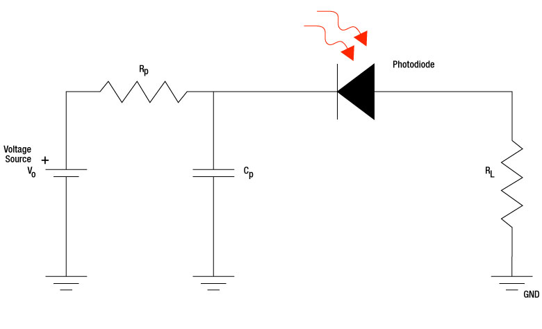
まず、モデルを作るために、Figure 171AFに示すフォトダイオードの回路に対してオームの法則を適用します。DC電圧源を一定と仮定すると、次の式が得られます。
Veff = V0 - iPD * (RP + RL)
(1)
フォトダイオードの有効バイアス電圧(Veff)は、電源電圧(V0)から、バイアスモジュールの抵抗(RP)と負荷抵抗(RL)の和に光電流 (iPD)を掛けた値を差し引いた値に等しくなります。
Veffが入射光パワー(P)によってどのように変化するかを見るために、上の式のiPDを定義に従って波長に依存するフォトダイオードの感度[ℜ(λ)] とPの積に置き換えます。
iPD = ℜ(λ) * P
(2)
負荷抵抗にオームの法則を適用してiPD = VL / RLとすることで、上の式からℜ(λ)は次のように書くことができます。
ℜ(λ) = VL / (P * RL )
(3)
負荷抵抗(VL)による電圧低下はPの増加量に比例すると仮定すると、VLとP の変化量の比は次のように表されます。
m = Δ VL / Δ P
(4)
これらの式を組み合わせると、次の式が得られます。
Veff = V0 - (m / RL) * P * (RP + RL)
(5)
mの値は各フォトダイオードのVLおよびPの測定値から計算できるため、この式はPに応じたVeffの変化を示すモデルとして使用できます。
実験
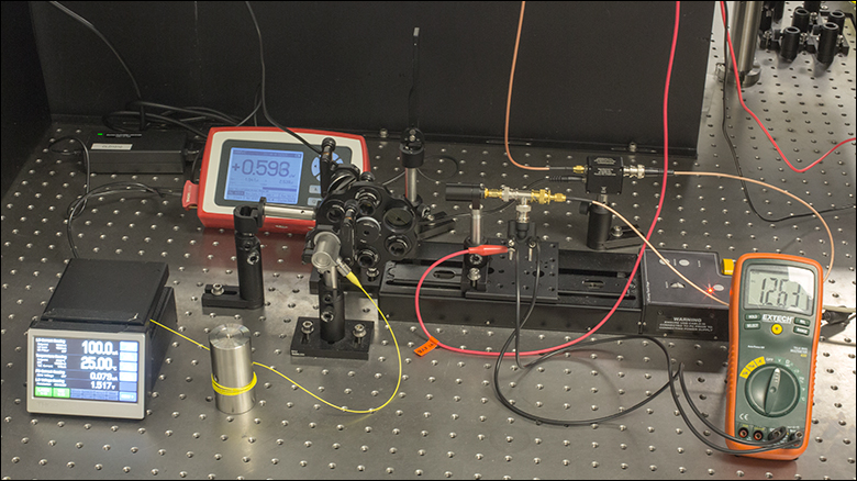
この実験ではPの変化に対するVLの変化を測定しました。ファイバに結合された半導体レーザからの出力光を、コリメートしたのちにNDフィルタを通し、さらに軸外放物面ミラーで被試験デバイス(DUT)に集光しました。実験セットアップの写真はFigure 171AEでご覧いただけます。様々な光学濃度のNDフィルタを使用することで、フォトダイオードへの入射光パワーを変化させました。使用したフォトダイオードごとに受光面と集光ミラー間の距離を調整し、スポットサイズがフォトダイオードの受光面積の約半分となるようにしました。V0、VL、およびVeff+VLの測定にはオシロスコープを使用しました。有効バイアスの測定にはマルチメータを直接使用しました。
結果
各DUTについてPに対するVLをグラフ化しました。Siフォトダイオードの結果例がFigure 171AGでご覧いただけます。データセット毎に直線のトレンドラインを作成しましたが、その勾配が式(4)のmになります。この値を式(5)に用いて有効バイアス電圧を求めることができます。また、Veffの入射光パワーに対する特性をグラフ化し、オシロスコープによる測定値と比較することができます。それらの結果は、Figure 171AH、171AJ、171AKに示されています。ここに示したモデルは実験による測定結果と整合性があることが分かり、それらの結果は(V0、RPおよび RLが一定の場合には)Pが増加するとともにVeffが減少することを示しています。これは重要な結果です。なぜなら電圧源に設定した電圧が必ずしもフォトダイオードに印加されるバイアス電圧にはならないからです。フォトダイオードに印加される有効バイアス電圧を求めるには、回路内の部品の抵抗を考慮しなければなりません。
 Click to Enlarge
Figure 171AE こちらの実験セットアップはフォトダイオードの有効電圧のモデルを検証するために使用されました。
Click to Enlarge
Figure 171AF バイアス電圧が印加されたフォトダイオードの電子回路図
_Plot_G1-780.gif)
Click to Enlarge
Figure 171AG 式(5)のmを求めるために使用された入射光パワーと電圧の関係
_Power_Plot_G1-780.gif)
Click to Enlarge
Figure 171AK SM05PD6Aの有効バイアス(測定値と
モデルによる計算値)
_Power_Plot_G1-780.gif)
Click to Enlarge
Figure 171AJ SM05PD5Aの有効バイアス(測定値と
モデルによる計算値)
_Power_Plot_G1-780.gif)
Click to Enlarge
Figure 171AH SM05PD1Aの有効バイアス(測定値と
モデルによる計算値)
About Our Lab Facts
Our application engineers live the experience of our customers by conducting experiments in Alex’s personal lab. Here, they gain a greater understanding of our products’ performance across a range of application spaces. Their results can be found throughout our website on associated product pages in Lab Facts tabs. Experiments are used to compare performance with theory and explore the benefits and drawbacks of using similar products in unique setups, in an attempt to understand the intricacies and practical limitations of our products. In all cases, the theory, procedure, and results are provided to assist with your buying decisions.
パルスレーザ:パワーとエネルギーの計算

パルスレーザからの放射光が、使用するデバイスや用途に適合するかどうかを判断する上で、レーザの製造元から提供されていないパラメータを参照しなければならない場合があります。このような場合、一般には入手可能な情報から必要なパラメータを算出することが可能です。次のような場合を含めて、必要な結果を得るには、ピークパルスパワー、平均パワー、パルスエネルギ、その他の関連するパラメータを必要とすることがあります。
- 生物試料を損傷させないように保護する
- フォトディテクタなどのセンサにダメージを与えることなくパルスレーザ光を測定する
- 物質内で蛍光や非線形効果を得るために励起を行う
パルスレーザ光のパラメータはFigure 170AおよびTable 170Bに示します。参照用として、計算式の一覧を以下に示します。資料を ダウンロードしていただくと、これらの計算式のほかに、パルスレーザ光の概要、異なるパラメータ間の関係性、および計算式の適用例がご覧いただけます。
計算式 | ||||
 | 、 |  | ||
 | ||||
 | ||||
 | ||||
平均パワーから算出するピークパワー、ピークパワーから算出する平均パワー : | ||||
 | 、 |  | ||
| 平均パワーおよびデューティーサイクルから算出するピークパワー*: | ||||
 | *デューティーサイクル( ) はレーザのパルス光が放射されている時間の割合です。 ) はレーザのパルス光が放射されている時間の割合です。 | |||
Click to Enlarge
Figure 170A パルスレーザ光の特性を記述するためのパラメータを、上のグラフとTable 170Bに示します。パルスエネルギ (E)は、パルス曲線の下側の黄色の領域の面積に対応します。このパルスエネルギは斜線で表された領域の面積とも一致します。
| Table 170B パルスのパラメータ | |||||
|---|---|---|---|---|---|
| パラメータ | シンボル | 単位 | 説明 | ||
| パルスエネルギ | E | ジュール[J] | レーザの1周期中に放射される1パルスの全放射エネルギ。 パルスエネルギはグラフの黄色の領域の面積に等しく、 これは斜線部分の面積とも一致します。 | ||
| 周期 | Δt | 秒 [s] | 1つのパルスの開始から次のパルスの開始までの時間 | ||
| 平均パワー | Pavg | ワット[W] | パルスとして放射されたエネルギが、1周期にわたって 均一に広がっていたと仮定したときの、 光パワーの大きさ(光パワー軸上の高さ) | ||
| 瞬時パワー | P | ワット[W] | 特定の時点における光パワー | ||
| ピークパワー | Ppeak | ワット [W] | レーザから出力される最大の瞬時パワー | ||
| パルス幅 |  | 秒 [s] | パルスの開始から終了までの時間。一般的にはパルス形状の 半値全幅(FWHM)を基準にしています。 パルス持続時間とも呼ばれます。 | ||
| 繰り返し周波数 | frep | ヘルツ [Hz] | パルス光が放射される頻度を周波数で表示した量。 周期とは逆数の関係です。 | ||
計算例
下記のパルスレーザ光を測定するのに、最大入力ピークパワーが75 mW
のディテクタを使用するのは安全かどうかを計算してみます。
- 平均パワー: 1 mW
- 繰り返し周波数: 85 MHz
- パルス幅: 10 fs
1パルスあたりのエネルギは、

と低いようですが、ピークパワーは、

となります。このピークパワーはディテクタの
最大入力ピークパワーよりも5桁ほど大きく、
従って、上記のパルスレーザ光を測定するのに
このディテクタを使用するのは安全ではありません。
| Posted Comments: | |
Esteban MONSALVO
(posted 2024-09-20 08:44:29.583) Dear Mr THORLABS,
I would like to purchase your calibrated photodiode FDS1010-CAL. I was wondering if it is appropriate for absolute quantum efficiency measure using QTH source and how to mount it on an optical breadboard ? fmortaheb
(posted 2024-12-17 04:30:34.0) Dear customer, thank you very much for your feedback. In principle this calibrated photodiode can be used for quantum efficiency measurements. However, you would have to use a monochromator additionally to filter the wavelengths of the broadband source. I will contact you directly to discuss this in more detail with you. Jeoungmin Ji
(posted 2024-05-27 18:10:26.093) Would you please provide the ideal detectivity files for FDS100-CAL and FDS1010-CAL? I can find only the responsivity files here. hchow
(posted 2024-05-28 06:27:48.0) Dear Mr. Ji, thank you for your feedback. Unfortunately, we do not have a detectivity vs wavelength graph. You can however, find out the detectivity of the FDS100-CAL and FDS1010-CAL via their NEP values. For the FDS100, it would be 1.2 x 10^-14 W/sqrt(Hz) @ 900nm, while for the FDS1010, it would be 2.07 x 10^-13 W/sqrt(Hz) @ 970nm. Hoang Luong
(posted 2023-08-27 10:47:09.197) Could you please provide calibration file for S/N: 230217205? I could not download it here. hchow
(posted 2023-08-29 09:12:10.0) Dear Mr. Luong, thank you for your feedback. I will personally reach out to you to provide the relevant information. Thank you. Angelo Pidatella
(posted 2023-06-07 10:03:26.847) Hello, I would be interested in purchasing your calibrated photodiode. However, I would like to know whether it is possible to get a "mounted" version of the same, or alternatively supporting me in buying the ancillary instruments/device to mount it by myself, guaranteeing the calibration traceability of the photodiode. Waiting for your response, I would like to thank you a lot in advance. fmortaheb
(posted 2023-06-08 08:58:14.0) Thank you very much for contacting us. I'll reach out to you directly to discuss your application. user
(posted 2023-04-18 16:32:29.62) Can I get the QE data below 800nm of FDG03-CAL? hchow
(posted 2023-04-19 08:17:02.0) Dear User, thank you for your feedback, I will personally reach out to you to provide the relevant information. Thank you. user
(posted 2023-03-22 10:51:50.513) Hello,
I would like to accurately measure very low light power (~200pW/cm^2). The conditions would be controlled and at a temperature of 21degC. Would you be able to recommend a photodiode and circuit that could measure such low light power reliably?
Regards,
Ronan dpossin
(posted 2023-03-24 06:21:28.0) Dear Ronan,
Thank you for your feedback. Since the NEP for the suggested diode is rated as 2.6 pw/sqrt(Hz), it is theoretical possible to measure such low powers. However the measurement accuracy is also dependent on the accuracy one is abole to measure the photocurrent accurately. I am reaching out to you in order to discuss this in more detail. Emanuele Malvisi
(posted 2023-02-09 13:14:06.243) Last year, we buyed the calibrated photodiodes FDS1010-CAL and FDG10X10-CAL. I use these detectors to determining light power (max 40 uW) from halogen light lamp source, with a monochromator, in the spectral range 350-1800 nm. In the overlap range 800-1100 nm of two detectors (used for determine a single curve), I observe the light power calculated with Ge photodiode is lower of light power calculated with Si photodiode than about 3.5-4%, this lower of your declared measurement uncertainty of ±5%. The shapes of two power curves are the same, but they differ by a "k" constant coefficient. The monochromtic beam dimensions are lower of cells size.
On active front side of cells, are there fingers?
Can you suggest me the main cause of this difference?
Thank you in advance for your support. hchow
(posted 2023-02-13 09:23:49.0) Dear Mr. Malvisi, thank you for your feedback. I believe the difference you are seeing in your power readings is due to the difference in responsivities of the two types of photodiodes. The FDS1010 Si photodiode responsivity peaks at around 1000 nm, whereas the FDG10X10 Ge photodiode responsivity peaks at 1550 nm. Given that Halogen light peaks at roughly 900 nn, you will definitely notice a difference in the amount of photocurrent generated by the two different photodiodes. In any case, I will personally reach out to you to provide you with more information. Thank you very much. Andrey Kuznetsov
(posted 2021-08-21 14:47:54.803) I sent an email to techsupport about getting my digital calibration certificate with all the values but have not received a response in a week! Please fix your certificate download tool, it says mine is not found. Also, please adjust your template to show more than 2 significant digits for the responsively values on the printout certificate to maybe 3 or 4. MKiess
(posted 2021-08-24 09:41:55.0) Dear Andrey, thank you very much for your feedback. Apologies that the download of the certificate did not work. I have sent you the appropriate certificates directly.
Showing more than two siginificant digits for responivity in the certificate is a good suggestion. We will discuss this internally and see if a change is possible. Thank you very much for this helpful feedback. user
(posted 2020-11-12 09:43:39.4) Hello. I cannot download any of my FDS100-CAL (SN: 201027208), FGA21-CAL (SN: 200928220), FDG03-CAL (SN: 201021220) data. Please, send me data of calibration. soswald
(posted 2020-11-13 03:30:54.0) This is a response from Sönke at Thorlabs: Thank you for your feedback. I have reached out to you directly to send you the calibration certiifcates as well as the raw data in electronic format. Adam Halverson
(posted 2020-01-07 14:48:47.36) What does NIST traceable mean? How accurate is the calibration? MKiess
(posted 2020-01-08 06:40:35.0) This is a response from Michael at Thorlabs. Thank you very much for your inquiry. NIST traceable means that the equipment we use for calibration has an unbroken chain of measurements that is traceable to national and international standards. In the case of NIST, this is the National Instituite of Standards and Technology, or NIST for short.
For our calibrated sensors, all measurement uncertainties can be found on our website and are supplied in a separate calibration certificate. For our Calibrated Photodiodes, the measurement uncertainty is ±5% and we measure every 10nm over the spectral range of the photodiode. Further and more detailed information of our calibration process and traceability can be found in our Power Meter and Sensor Tutorial at the following link:
https://www.thorlabs.com/newgrouppage9.cfm?objectgroup_id=6188 user
(posted 2019-08-15 15:21:33.38) My product has just arrived. The serial number is: 190716305. The security code I continuously type in correctly. Currently, it says: md4xci. However, I cannot download any of my FDS1010-CAL data. Please assist.
Thank You!
A.J. Matthews
Toledo Solar MKiess
(posted 2019-08-20 04:15:40.0) This is a response from Michael at Thorlabs. Thank you very much for your feedback! I have contacted you directly to send you the data. user
(posted 2019-05-12 00:54:46.333) N0 cal. data
- 190122212
- 190122210 lmorgus
(posted 2019-05-13 09:07:57.0) A response from Laurie at Thorlabs: Thank you for noting that there is an issue with the ability to download serialized information. I will reach out to you directly with the requested files while we work to ensure these are available for download from our website. user
(posted 2019-05-12 00:47:50.46) I couldnot download the calibration data of
sn 190205318 (FDS100-cal) lmorgus
(posted 2019-05-13 09:01:35.0) A response from Laurie at Thorlabs: Thank you for noting that there is an issue with the ability to download serialized information. I will reach out to you directly with the requested files while we work to ensure these are available for download from our website. claudios
(posted 2019-01-14 16:36:57.417) Hello,
can you give me a quote for a calibrated and mounted FDS100 Si photodiode, type SM05PD1A? Is the calibration done focusing the light only at the center of the device or illuminating the whole active area? In the former case, does a uniform complete illumination of the device affect the responsivity obtained with the calibration? wskopalik
(posted 2019-01-16 07:22:32.0) This is a response from Wolfgang at Thorlabs. Thank you very much for your feedback!
Yes, we can offer a calibrated version of the SM05PD1A as well. In the calibration setup a beam with about 2mm in diameter is used. So a large part of the active area of the SM05PD1A is illuminated. In general, the responsivity of photodiodes is also quite uniform over the photodiode surface. You can find more information about the spatial uniformity of photodiodes in the “Lab Facts” section of our website (https://www.thorlabs.com/newgrouppage9.cfm?objectgroup_id=10741&tabname=Spatial%20Uniformity).
I will contact you directly to provide further information and also a quote. s.krause
(posted 2017-07-31 09:45:28.43) We bought a FDS1010-CAL to measure light intensities without applying bias voltage, just connecting the diode to an Pico-Amperemeter. I wonder how linear the response is to incident light level? Do you have any numbers, until which current output it is linear (within 1%)?
Best, Sascha tfrisch
(posted 2017-07-31 03:36:54.0) Hello, thank you for contacting Thorlabs. We have some information on the theory of saturation in the below lab facts. It will depend on a number of factors including the bias voltage, built-in voltage, responsivity, load resistance and series resistance, but likely the detector would be completely saturated at a few mW with no bias voltage, and non-linear performance would begin before that. For the built in voltage of a silicon diode, 0.6V is a fair estimate, but you can get a more accurate measurement by finding the output voltage at saturation with a large load resistor.
https://www.thorlabs.us/images/TabImages/Photodetector_Lab.pdf hakan.pettersson
(posted 2017-03-21 19:34:14.967) I wonder at which bias the provided responsivity data for the FDS100-CAL is recorded at. Also, can the responsivity simply be scaled with bias according to a simply relation?
All the best
HåkanP swick
(posted 2017-03-22 06:15:53.0) This is a response from Sebastian at Thorlabs. Thank you for the inquiry.
The calibration is performed without bias voltage. Unfortunately, there is no simple relation between responsivity and bias. The calibration data is only valid without bias. Jeff.Wheeldon
(posted 2016-06-08 16:01:31.357) Could you tell me the highest measurable power using FDG05-CAL. We regularly measure total powers of 45 mW is this within the specification for this product? besembeson
(posted 2016-06-09 09:18:53.0) Response from Bweh at Thorlabs USA: That may be too high. At peak responsivity (1550nm) for example with 45mW, you will be around 38mA of output generated current, and you will be saturating the detector. Depending on your wavelength, you want to keep optical power level such that output current is under 1mA to stay in the linear regime for the detector. dojin78
(posted 2014-03-18 10:49:01.103) Could you tell me the difference FGA21-CAL and FGA21? alexandru.serb05
(posted 2013-09-03 11:01:18.603) Do we know what the optical damage threshold for this product is (and for that matter for all of them)? In other words beyond what sort of irradiance will I start frying the device? I suspect this will be wavelength dependent so ideally there will be some sort of plot showing damage threshold in W/M^2 vs wavelength, but if not, some rough figure would also be very helpful.
Thanks jlow
(posted 2013-09-04 09:36:00.0) Response from Jeremy at Thorlabs: The photodiode will start to saturate well before damage would occur. In general, I would recommend keeping the current output from the photodiode to be <1mA to avoid saturating the photodiode. I will get in contact with you to discuss about your application further. bdada
(posted 2011-11-17 15:29:00.0) Response from Buki at Thorlabs:
Thank you for your feedback. We can provide the calibrated version of the SM05PD1A. We will contact you regarding a quote. gert
(posted 2011-11-17 15:09:23.0) Can you give us a price for a calibrated and mounted FDS100 Si photodiode, type SM05PD1A ?
Thank you,
Gert Raskin jjurado
(posted 2011-02-24 14:33:00.0) Response from Javier at Thorlabs to rjaculbia: Thank you for contacting us with your request. We currently do not offer mounts or adapters for easily mounting the calibrated photodiodes. However, we can offer these already mounted in SM05 and SM1 compatible tubes with SMA or BNC output connectors as special items. Please visit the link below:
http://www.thorlabs.com/NewGroupPage9.cfm?ObjectGroup_ID=1285
I will contact you directly to get information about your selection. rbjaculbia
(posted 2011-02-24 01:04:07.0) hi, how do we mount these diodes in a setup? can this be mounted using the s1lm9? Thanks apalmentieri
(posted 2010-01-20 15:33:04.0) A response from Adam at Thorlabs: The calibration data is in the form of an excel data table with a wavelength resolution of 10nm. When calibrating these diodes, we do not use fiber coupling methods. We use a monochromator with an output beam diameter of 1.7mm so not to overfill the aperture. The accuracy of +/-5% is a tolerance that includes any measurement errors, for instance shot noise and johnson noise from the detector, that must be taken into account while calibrating the diode to NIST traceable standards. markus.blaser
(posted 2010-01-20 11:05:25.0) Few questions with respect to FGA21-CAL:
In which form is the calibration data availabe:
Data Table ? Wavelength resolution ?
What is the optical coupling method used for the calibration procedure:
Butt Fiber / Angled Fiber or other coupling technique ?
Why is the accuracy only +/- 5%, when the detector is calibrated against a NIST traceable reference detector ? |
下表は、当社のフォトダイオードタイプのディテクタ、フォトコンダクティブ型ディテクタ、焦電ディテクタの一覧です。同一の列に記載されている型番の検出素子は同じです。
")
 ズーム
ズーム当社ではNISTトレーサブルな校正済みSiフォトダイオード2種類を在庫で取り揃えています。Siフォトディテクタは可視域から近赤外域で感度があります。FDS100-CALとFDS1010-CALは受光部の広いSiフォトディテクタで、それぞれカンと正方形のセラミック基板にパッケージされています。これらの製品の仕様の詳細や、感度特性、暗電流、静電容量のグラフをご覧いただくにはTable G1.1.のInfoアイコンをクリックしてください。
当社では、こちらのSiフォトディテクタの応答の一様性を向上させるように設計されたスペクトル特性平坦化フィルタもご用意しています。詳細は、 こちらをご参照ください。
| Table G1.1 Specifications | ||||||||||
|---|---|---|---|---|---|---|---|---|---|---|
| Item # | Info | Wavelength | Active Area | Rise/Fall Timea | NEP (W/Hz1/2) | Dark Current | Capacitance | Package | Vbias,max | Compatible Sockets |
| FDS100-CAL | 350 - 1100 nm | 13 mm2 | 10 ns @ 632 nm, 20 V | 1.2x10⁻¹⁴ @ 900 nm, 20 V | 1.0 nA @ 20 V (Typ.) | 24 pF @ 20 V (Typ.) | TO-5 Can (Ø0.36") | 25 V | STO5S STO5P | |
| FDS1010-CAL | 350 - 1100 nm | 100 mm2 | 65 ns @ 632 nm, 5 V | 2.07x10⁻¹³ @ 970 nm, 5 V | 600 nA @ 5 V (Max) | 375 pF @ 5 V (Typ.) | 0.45" x 0.52" Ceramic Wafer | 25 V | Not Available | |
")
 ズーム
ズーム当社ではNISTトレーサブルな校正済みGeフォトダイオードをご用意しております。Geフォトディテクタは800~1800 nmの近赤外域で感度があります。FDG03-CALは1300~1550 nm域のARコーティングが施されていて、カンにパッケージされています。この製品の仕様の詳細や、感度特性、暗電流、静電容量のグラフをご覧いただくにはTable G2.1のInfoアイコンをクリックしてください。
")
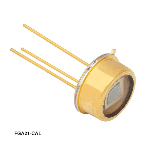 ズーム
ズーム当社ではNISTトレーサブルな校正済みInGaAsフォトダイオードを在庫で取り揃えています。InGaAsフォトディテクタは800~1700 nmの近赤外域で感度があります。FGA21-CAL のPIN構造により、ゼロバイアスで高速の立ち上がり/立ち下がり時間を示します。この製品の仕様の詳細や、感度特性、暗電流、静電容量のグラフをご覧いただくにはTable G3.1のInfoアイコンをクリックしてください。