 Products Home
ファイバー出力型レーザー光源:可視域用

- SM, MM, and PM Sources Available
- Full Output Powers from 2.5 to 50.0 mW
- Stable, Low Noise, Constant Power Operation
S1FC660
660 nm, 15.0 mW
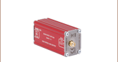
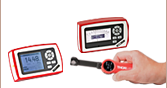
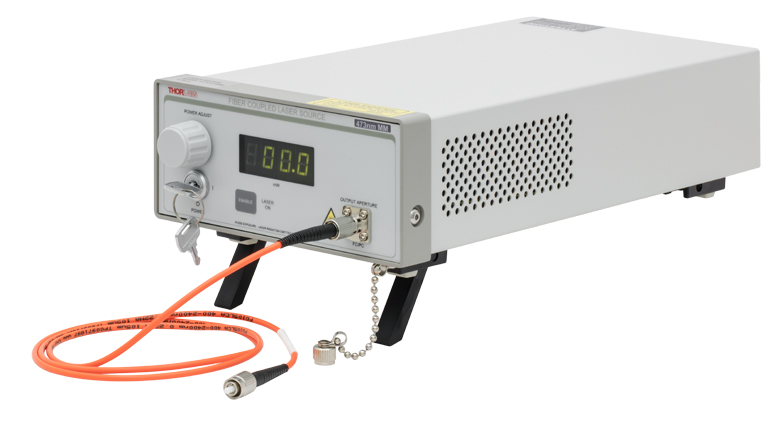
Front Panel Display Provides an Enable Button, Laser Power Control, and Display Screen


Please Wait
| Single Channel Benchtop Laser Sources Selection Guide | |||||
|---|---|---|---|---|---|
| Spectrum | Wavelength | TEC | Laser Type | Cavity Type | Output Fiber Type |
| Visible | 405 - 675 nm | No | Semiconductor | Fabry Perot | SM, MM, or PM |
| 405 - 685 nm | Yes | Semiconductor | Fabry Perot | SM | |
| NIR | 785 - 1550 nm | No | Semiconductor | Fabry Perot | SM or PM |
| 705 - 2000 nm | Yes | Semiconductor | Fabry Perot | SM | |
| 1310 - 1550 nm | Yes | Semiconductor | DFB | SM | |
| 1900 - 2000 nm | N/A | Fiber Laser | Fabry Perot | SM | |
| MIR | 2.7 µm | N/A | Fiber Laser | Fabry Perot | SM |
| Other Fiber-Coupled Laser Sources | |||||
特長
- 波長:
- シングルモード(SM):405 nm~675 nm
- マルチモード(MM): 473 nm
- 偏波保持(PM): 635 nm
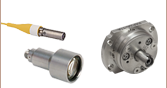
- FC/PCのシングルモードまたはマルチモードファイバーインターフェイス
- 出力レベルはノブの回転またはBNC変調入力端子への入力電圧で調整可能
- 安定で低ノイズな一定出力動作
- インターロック回路は2.5 mmモノラルジャックに接続
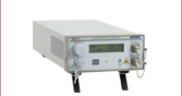
当社では、可視域のスペクトルで発光するシングルモードファイバ、マルチモードファイバ、もしくは偏波保持ファイバ出力のレーザ光源をご用意しています。このベンチトップ型のレーザ光源には、いずれもピグテール付きファブリペロー型半導体レーザと電流コントローラが内蔵されています。
レーザ光源の前面パネルには、出力値(mW)を表示するデイスプレイ、ON/OFFキー、Enableボタン、そしてレーザ出力調整ノブがあります。背面パネルには、外部からのDCまたは正弦波電圧信号によって半導体レーザの駆動電流を制御するためのBNC入力端子と、インターロック用リモートコントロール入力端子が付いています。
当社のシングルチャンネルベンチトップ型レーザ光源の全てのラインナップは右の表をご参照ください。
| Key Specificationsa | ||||||||
|---|---|---|---|---|---|---|---|---|
| Item # | S1FC405 | S1FC635 | S1FC637 | S1FC660 | S1FC675 | S1FC473MM | S1FC635PM | |
| Fiber Type | SM | MM | PM | |||||
| Wavelength | 405 nm | 635 nm | 637 nm | 660 nm | 675 nm | 473 nm | 635 nm | |
| Spectrum |  |  |  |  | - | - | ||
| Full Output Power | 8.0 mW (Min) | 2.5 mW (Min) | 8.0 mW (Min) | 15.0 mW (Min) | 2.5 mW (Min) | 50.0 mW (Max) | 2.5 mW (Min) | |
| Power Stability | 15 min: ±0.05 dB, 24 hr: ±0.1 dB (After 1 hr Warm-up at 25 ± 10 °C Ambient) | |||||||
| Single Mode Source Specifications | |||||||
|---|---|---|---|---|---|---|---|
| Item # | S1FC405 | S1FC635 | S1FC637 | S1FC660 | S1FC675 | ||
| Wavelength | Minimum | 395 nm | 625 nm | 630 nm | 645 nm | 660 nm | |
| Typical | 405 nm | 635 nm | 637 nm | 660 nm | 675 nm | ||
| Maximum | 415 nm | 640 nm | 645 nm | 665 nm | 680 nm | ||
| Spectruma | | | | | |||
| Minimum Full Output Power | 8.0 mW | 2.5 mW | 8.0 mW | 15.0 mW | 2.5 mW | ||
| Setpoint Resolution | 0.01 mW | 0.01 mW | 0.01 mW | 0.01 mW | 0.01 mW | ||
| Laser Class | 3B | 3R | 3B | 3B | 3R | ||
| Fiber | |||||||
| Fiber Type | S405-XP | SM600 | SM600 | SM600 | SM600 | ||
| Mode Field Diameterb | 3.3 µm @ 405 nm | 3.6 - 5.3 µm | 3.6 - 5.3 µm | 3.6 - 5.3 µm | 3.6 - 5.3 µm | ||
| Numerical Aperture | 0.12 | 0.10 - 0.14 | 0.10 - 0.14 | 0.10 - 0.14 | 0.10 - 0.14 | ||
| Output Fiber Connector | FC/PC, Wide 2.1 mm Key Compatible | ||||||
| Electrical | |||||||
| Power Stability | 15 min: ±0.05 dB, 24 hr: ±0.1 dB (After 1 hr Warm-Up at 25 ± 10 °C Ambient) | ||||||
| Display Accuracy | ±10% | ||||||
| Adjustment Range | ~0 mW to Full Power | ||||||
| Input Power | 115 VAC / 230 VAC (Switch Selectable) 50 - 60 Hz | ||||||
| Modulation Input | 0 - 5 V = 0 - Full Power, DC or Sine Wave Input Only | ||||||
| Modulation Bandwidth | 5 kHz Full Depth of Modulation 30 kHz Small Signal Modulation | ||||||
| Environmental | |||||||
| Operating Temperature | 15 to 35 °C | ||||||
| Storage Temperature | 0 to 50 °C | ||||||
| Multimode Source Specifications | |
|---|---|
| Item # | S1FC473MM |
| Wavelength | 473 nm |
| Maximum Output Powera | 50.0 mW |
| Stability | 15 min: ±0.05 dB, 24 hr: ±0.1 dB (After 1 hr Warm-Up at 25 ± 10 °C Ambient) |
| Display Accuracy | ±10 % |
| Setpoint Resolution | 0.1 mW |
| Adjustment Range | ~0 mW to Full Power |
| AC Input | 115 / 230 VAC (Switch Selectable) 50 - 60 Hz |
| Modulation Input | 0 - 5 V = 0 - Full Power, DC or Sine Wave Input Only |
| Modulation Bandwidth | 5 kHz Full Depth of Modulation 30 kHz Small Signal Modulation |
| Fiber | FG105UCA |
| Environmental | |
| Operating Temperature | 15 to 35 °C |
| Storage Temperature | 0 to 50 °C |
| Polarization-Maintaining Source Specifications | ||||
|---|---|---|---|---|
| Item # | S1FC635PM | |||
| Wavelengtha | 635 nm | |||
| Minimum Full Output Power | 2.5 mW | |||
| Stability | 15 min: ±0.05 dB, 24 hr:±0.1 dB (After 1 hr Warm-Up at 25 ± 10 °C Ambient) | |||
| Display Accuracy | ±10% | |||
| Setpoint Resolution | 0.01 mW | |||
| Adjustment Range | ~0 mW to Full Power | |||
| Minimum Polarization Extinction Ratio | 15 dB | |||
| Environmental | ||||
| Operating Temperature | 15 to 35 °C | |||
| Storage Temperature | 0 to 50 °C | |||
| AC Input | 115 VAC / 230 VAC (Switch Selectable) 50 - 60 Hz | |||
| Modulation Input | 0 - 5 V = 0 - Full Power, DC or Sine Wave Input Only | |||
| Modulation Bandwidth | 5 kHz Full Depth of Modulation 30 kHz Small Signal Modulation | |||
| Fiber | PM630-HP | |||
変調入力端子
BNCメス型
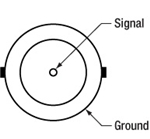
0~5 Vまで、50 Ω
リモートインターロック入力端子
2.5 mmモノラルジャック
レーザのON状態をENABLEとするには、端子間を付属のプラグまたは外部スイッチのようなユーザ所有のデバイスで短絡する必要があります。
レーザの安全性とクラス分類
レーザを取り扱う際には、安全に関わる器具や装置を適切に取扱い、使用することが重要です。ヒトの目は損傷しやすく、レーザ光のパワーレベルが非常に低い場合でも障害を引き起こします。当社では豊富な種類の安全に関わるアクセサリをご提供しており、そのような事故や負傷のリスクの低減にお使いいただけます。可視域から近赤外域のスペクトルでのレーザ発光がヒトの網膜に損傷を与えうるリスクは極めて高くなります。これはその帯域の光が目の角膜やレンズを透過し、レンズがレーザーエネルギを、網膜上に集束してしまうことがあるためです。
 |  |  |
 |  |  |
 |  |  |
安全な作業および安全に関わるアクセサリ
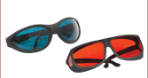
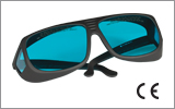
- クラス3または4のレーザを取り扱う場合は、必ずレーザ用保護メガネを装着してください。
- 当社では、レーザのクラスにかかわらず、安全上無視できないパワーレベルのレーザ光線を取り扱う場合は、ネジ回しなどの金属製の器具が偶然に光の方向を変えて再び目に入ってしまうこともあるので、レーザ用保護メガネを必ずご使用いただくようにお勧めしております。
- 特定の波長に対応するように設計されたレーザ保護眼鏡は、装着者を想定外のレーザ反射から保護するために、レーザ装置付近では常に装着してください。
- レーザ保護眼鏡には、保護機能が有効な波長範囲およびその帯域での最小光学濃度が刻印されています。
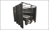
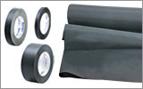
- レーザ保護カーテンやレーザー安全保護用布は実験室内での高エネルギーレーザの遮光にご使用いただけます。
- 遮光用マテリアルは、直接光と反射光の両方を実験装置の領域に封じ込めて外に逃しません。
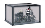
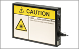
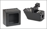
- 当社の筺体システムは、その内部に光学セットアップを収納し、レーザ光を封じ込めて危険性を最小限に抑えます。
- ピグテール付き半導体レーザは、他のファイバに接続、もしくは他のファイバとの接続を外す際には、レーザ出力をOFFにしてください。パワーレベルが10 mW以上の場合には特にご注意ください。
- いかなるビーム光も、テーブルの範囲で終端させる必要があります。また、レーザ使用中には、研究室の扉は必ず閉じていなければなりません。
- レーザ光の高さは、目線の高さに設定しないでください。
- 実験は光学テーブル上で、全てのレーザービームが水平を保って直進するように設定してください。
- ビーム光路の近くで作業する人は、光を反射する不要な装飾品やアクセサリ(指輪、時計など)をはずしてください。
- レンズや他の光学装置が、入射光の一部を、前面や背面で反射する場合がありますのでご注意ください。
- あらゆる作業において、レーザは必要最小限のパワーで動作するようにご留意ください。
- アライメントは、可能な限りレーザの出力パワーを低減して作業を行ってください。
- ビームパワーを抑えるためにビームシャッタや フィルタをお使いください。
- レーザのセットアップの近くや実験室には、適切なレーザ標識やラベルを掲示してください。
- クラス3Rやクラス4のレーザ(安全確保用のインターロックが必要となるレーザーレベルの場合)で作業する場合は、警告灯をご用意ください。
- ビームトラップの代用品としてレーザービュワーカードを使用したりしないでください。
レーザ製品のクラス分け
レーザ製品は、目などの損傷を引き起こす可能性に基づいてクラス分けされています。国際電気標準会議(The International Electrotechnical Commission 「IEC」)は、電気、電子工学技術関連分野の国際規格の策定および普及を行う国際機関で、IEC60825-1は、レーザ製品の安全性を規定するIEC規格です。レーザ製品のクラス分けは下記の通りです
| Class | Description | Warning Label |
|---|---|---|
| 1 | ビーム内観察用の光学機器の使用を含む、通常の条件下での使用において、安全とみなされているクラス。このクラスのレーザ製品は、通常の使用範囲内では、人体被害を及ぼすエネルギーレベルのレーザを発光することがないので、最大許容露光量(MPE)を超えることはありません。このクラス1のレーザ製品には、筐体等を開かない限り、作業者がレーザに露光することがないような、完全に囲われた高出力レーザも含まれます。 |  |
| 1M | クラス1Mのレーザは、安全であるが、望遠鏡や顕微鏡と併用した場合は危険な製品になり得ます。この分類に入る製品からのレーザ光は、直径の大きな光や拡散光を発光し、ビーム径を小さくするために光を集束する光学素子やイメージング用の光学素子を使わない限り、通常はMPEを超えることはありません。しかし、光を再び集光した場合は被害が増大する可能性があるので、このクラスの製品であっても、別の分類となる場合があります。 |  |
| 2 | クラス2のレーザ製品は、その出力が最大1 mWの可視域での連続放射光に限定されます。瞬目反射によって露光が0.25秒までに制限されるので、安全と判断されるクラスです。このクラスの光は、可視域(400~700 nm)に限定されます。 |  |
| 2M | このクラスのレーザ製品のビーム光は、瞬目反射があるので、光学機器を通して見ない限り安全であると分類されています。このクラスは、レーザ光の半径が大きい場合や拡散光にも適用されます。 | 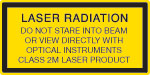 |
| 3R | クラス3Rのレーザ製品は、直接および鏡面反射の観察条件下で危険な可視光および不可視光を発生します。特にレンズ等の光学機器を使用しているときにビームを直接見ると、目が損傷を受ける可能性があります。ビーム内観察が行われなければ、このクラスのレーザ製品は安全とみなされます。このクラスでは、MPE値を超える場合がありますが、被害のリスクレベルが低いクラスです。可視域の連続光のレーザの出力パワーは、このレベルでは5 mWまでとされています。 | 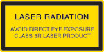 |
| 3B | クラス3Bのレーザは、直接ビームを見た場合に危険なクラスです。拡散反射は通常は有害になることはありませんが、高出力のクラス3Bレーザを使用した場合、有害となる場合もあります。このクラスで装置を安全に操作するには、ビームを直接見る可能性のあるときにレーザ保護眼鏡を装着してください。このクラスのレーザ機器にはキースイッチと安全保護装置を設け、さらにレーザ安全表示を使用し、安全照明がONにならない限りレーザがONにならないようにすることが求められます。Class 3Bの上限に近いパワーを出力するレーザ製品は、やけどを引き起こすおそれもあります。 | 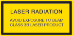 |
| 4 | このクラスのレーザは、皮膚と目の両方に損傷を与える場合があり、これは拡散反射光でも起こりうるとみなされています。このような被害は、ビームが間接的に当たった場合や非鏡面反射でも起こることがあり、艶消し面での反射でも発生することがあります。このレベルのレーザ機器は細心の注意を持って扱われる必要があります。さらに、可燃性の材質を発火させることもあるので、火災のリスクもあるレーザであるとみなされています。クラス4のレーザには、キースイッチと安全保護装置が必要です。 | 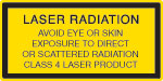 |
| 全てのクラス2以上のレーザ機器には、上記が規定する標識以外に、この三角の警告標識が表示されていなければいけません。 |  | |
| Posted Comments: | |
user
(posted 2024-01-23 11:27:40.983) Which is the maximum output power of the model S1FC405? ksosnowski
(posted 2024-01-23 11:50:22.0) Hello, thanks for reaching out to Thorlabs. Each unit is calibrated to achieve the maximum power for the particular laser diode used in the device. Due to variations in the coupling process, no two units will have the same exact maximum power. For S1FC405, we guarantee at least 8.0 mW on each unit we build. Ensuring that the patch cables used are always cleaned is an important measure to maintaining the output over the life of the laser, as any debris can cause backreflections which may damage the laser inside and cause reduced power. I have reached out directly to discuss this in further detail. Nazim Bharmal
(posted 2023-07-14 08:04:48.137) In your manual, there is no information regarding the modulation input connector type. That is only on the webpage (in small font) and via the 'Pin Diagrams' tab (arguably hidden). So I'd suggest modifying the manual to include the specification. cdolbashian
(posted 2023-07-21 11:50:13.0) Thank you for reaching out to us with this feedback. Within the manual, under the "Modulating the Laser Output" section (5.5), the first bullet point describes the required electrical connection. Regarding the hidden pin diagrams tab, we include such a tab on all pages which have devices with electrical outputs so that the information is visible and easily accessible without having to find it within a manual (in which it is also included). I have reached out to you directly to clarify this further. Tatsuo Yamaguchi
(posted 2023-07-05 13:26:23.857) お世話になっております。
御社のファイバレーザー光源S1FC660を購入したものです。
こちらの光源の光量のツマミを回したときの光量の安定するまでの時間についての仕様などはございますでしょうか?
感覚的な記述で恐縮なのですが、1mW→3mWまで光量を上げると、一度4mW程度まで上がりそのあと3mWまで下がるのに10-20秒程度かかっているという印象です。
よろしくお願いいたします。 cdolbashian
(posted 2023-07-14 04:11:48.0) Thank you for reaching out to us with this inquiry. A tech support agent has contacted your from our local office. user
(posted 2021-04-23 01:45:27.227) In my optical system,maybe about 20% laser power will back reflection into laser source.I am worried about back reflection light will damage laser source.Does this laser source include isolator?Thank you. YLohia
(posted 2021-04-23 11:35:06.0) Thank you for contacting Thorlabs. Unfortunately, such a high back reflection will damage the source since this doesn't come with an integrated isolator. That being said, a custom fiber based isolator for 635 nm can be ordered using the form on this page (https://www.thorlabs.com/newgrouppage9.cfm?objectgroup_id=3260) and be used right on the output to reduce the amount of backreflections going into the laser cavity. user
(posted 2019-05-21 14:13:05.223) In the product description you state
"... All of our fiber-pigtailed lasers utilize an angled fiber ferrule at the internal laser/fiber launch point to minimize reflections back into the laser diode, thereby increasing the stability of the laser diode's output."
And yet the specifications call out an FC/PC and not an FC/APC. I am confused. Can you please clarify? YLohia
(posted 2019-05-21 03:00:34.0) Hello, thank you for your feedback and bringing this typo to our attention. The specs are correct -- the items on this page (as of 5/2019) are FC/PC and not FC/APC (APC connections can be quoted as custom items by emailing techsupport@thorlabs.com). I am working with our technical marketing team to get this resolved. Please accept our apologies for any confusion caused by this. Andrey Kuznetsov
(posted 2019-05-01 14:28:16.583) NOTICE to Customers: I compared 630HP and SM600 fibers when connected to these Fiber sources. These sources have an internal SM600 fiber from the diode to the front bulkhead connector. Thorlabs rightly says to use cables of the same type, however even though 630HP and SM600 share almost exactly the same parameters like NA, etc, based on my tests: 630HP insertion can cause output attenuation up to 95%, while SM600 fiber attenuation was only up to 20%. The issue I had was that when inserting a fiber into the bulkhead, with the key polarizer aligned, rotating and tightening the connector would result in an unpredictable attenuation of light output as measured with a photodiode. We're now switching to SM600 fibers to avoid severe attenuation losses due to fiber coupling issues. Thorlabs should explicitly state this on the Overview page in bold letters that customers must use SM600 fiber to avoid huge attenuation losses due to coupling. mmcclure
(posted 2019-05-02 10:52:01.0) Hello, thank you for your feedback. Yes, for our single mode fiber-coupled laser sources, we recommend using a single mode patch cable that is the same fiber type as the fiber-pigtailed laser inside the device. We will make this recommendation more explicit on the webpage. akuznetsov
(posted 2018-09-27 19:42:45.16) What is the fiber core size inside these laser bench sources?
What core size fiber patch cable should I use to optimize light throughput? YLohia
(posted 2018-09-28 11:33:03.0) Hello, the fiber types used are listed in the Specs tab: https://www.thorlabs.com/newgrouppage9.cfm?objectgroup_id=1500&tabname=Specs along with the MFD and NA. In order to maximize coupling efficiency, you should use the same fiber or a multimode fiber with a larger MFD and NA than the one used in the benchtop unit. akuznetsov
(posted 2018-09-27 17:33:36.43) We have a S1FC637 and we see that 637*2=1274nm wavelength is also present on the output, is this normal? Shouldn't there be a filter in the unit to prevent the doublet from outputting?
We are using the 637nm to excite emission in the NIR so the 1274nm output from the laser is interfering with out results. YLohia
(posted 2018-10-03 03:02:17.0) Hello, thank you for contacting Thorlabs. This is certainly not normal and not expected of a GaAs-based chip. I took a few scans of the S1FC637 with our OSA207C optical spectrum analyzer and did not find any significant emission around 1274nm (at max output power setting). Based on our correspondence, the issue was being caused by the small fraction of the stimulus light (1274nm) being fed into the spectrometer since the stimulus and collection path were the same. melanie
(posted 2018-09-04 08:20:38.627) 1.What is the laser threshold power for S1FC635PM ?
2.Would you consider making a PM fibre-coupled green laser ? nbayconich
(posted 2018-09-25 10:17:46.0) Thank you for contacting Thorlabs. We do not specify a threshold power for the S1FC635PM benchtop source however the setpoint resolution is 0.01mW and can be adjusted from 0 - 2.5mW. The threshold current for the diode is about 50mA and the minimum range is set to just below the lasing threshold. The output is mostly off but there will be a very small amount of light still present since a small amount of light is needed for the power control circuit to be active.
I will reach out to you directly to discuss our custom capabilities. melanie
(posted 2017-03-23 13:05:57.74) I have 2 questions:
1) If connected to one of your PM patchcords, what will be the typical polarisation extinction when the light emerges from the patchcord ?
2) If we turn the laser right down, will it become incoherent ? (this is useful to us)
Thanks,
Melanie tfrisch
(posted 2017-03-30 01:17:52.0) Hello Melanie, thank you for contacting Thorlabs. When used with a PM patch cable, S1FC635PM has an extinction ratio of >20dB. As for the laser power, this unit is not intended for operation below the threshold current of the diode. I will reach out to you directly to discuss your application. acable
(posted 2008-08-15 10:52:31.0) Related Products… please think about the related products that are most often used with the product that is being featured. In the case of the fiber coupled laser sources it would probably be: patch cable, collimation package, and perhaps a mirror mount and adapter to hold and aim the collimated light field.
I would even think about adding a little text by each price box with a labeled photo of the parts all connected together, with a kit being offered for each of the wavelengths. I would then use the Related Products links (and refer to them in the text) to allow the customer to put together their own parts list (longer cables, different collimation packages, different mounts). |

 ズーム
ズーム- 405~675 nmの5種類の波長をご用意
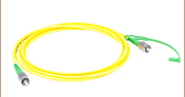
- FC/PCシングルモードファイバーインターフェイス
- 最大出力:2.5 mW~15.0 mW
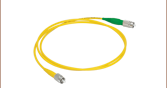
- ファイバーパッチケーブルは別売りでご用意
- カスタム波長もご提供可能(当社までお問い合わせください)
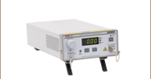
こちらのシングルモードファイバ出力型レーザ光源は、ピグテール付きファブリペロー型半導体レーザと電流コントローラを1つのベンチトップ型ユニットに納めた製品です。各ユニット内のファブリペローレーザにはシングルモードファイバが接続されており、それらは前面パネルに取り付けられたFC/PCバルクヘッド(ワイドキー、ナローキーに対応)に接続されています。当社では前面パネルのバルクヘッドに接続するためのシングルモードファイバーパッチケーブルをご用意しております。接続損失を抑えるためにはレーザ装置内部で使用されているファイバと同じ種類のファイバーパッチケーブルを使用することをお勧めいたします。内部で使用されているファイバについては「仕様」タブをご覧ください。後方反射によるノイズを低減するために、レーザ光源に接続されたFC/PCコネクタに対して、ハイブリッド型のFC/PC-FC/APCケーブルのご使用をお勧めいたします。
前面パネルには、出力値(mW)を表示するデイスプレイ、ON/OFFキー、Enableボタン、そしてレーザ出力調整ノブがあります。背面パネルには、外部からのDCまたは正弦波電圧信号によって半導体レーザの駆動電流を制御するための入力端子と、インターロック用リモートコントロール入力端子が付いています。
注:この光源に他のファイバを接続したり、取り外したりする際には、レーザ出力をOFFにしてください。パワーレベルが10 mW以上の場合には、特にご注意ください。
635 nmの光源を使用する用途には、USBインターフェイス付きの小型ファイバ出力レーザ光源もご用意しています。 オプトジェネティクス用途には、マルチモードファイバを組み込んだ473 nmベンチトップ型レーザ光源をご用意しています。偏光出力用には、偏波保持ファイバを組み込んだレーザ光源も取り揃えています(下記をご参照ください)。波長可変レーザが必要な通信用途については、当社のベンチトップ型波長可変レーザ光源のページをご覧ください。カスタム波長のレーザ光源、またはFC/APCファイバーインターフェイスをご希望の場合には、当社までご連絡ください。

 ズーム
ズーム- 出力波長: 473 nm
- FC/PCマルチモードファイバーインターフェイス
- 50.0 mWの出力パワー
- ファイバーパッチケーブルは別売りでご用意
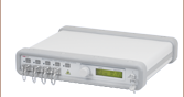
ファイバ出力型レーザS1FC473MMは出力パワー50.0 mW、出力波長473 nmで、数多くのオプトジェネティクス用途に適した光源となっています。この製品は、ピグテール付きFP半導体レーザと電流コントローラが1つのベンチトップ型ユニットに納められています。ユニットの出力は、5 kHzの全幅および30kHzの小信号で外部変調することもできます。出力はFC/PCコネクタ付きのマルチモードファイバFG105UCAとなっています。このユニットは当社の様々な種類のマルチモードパッチケーブルならびにオプトジェネティクス製品に対応しています。
前面パネルには、出力値(mW)が表示できるディスプレイ、ON/OFFキー、Enableボタン、そしてレーザ出力調整ノブがあります。背面パネルには、外部からの電圧信号によって半導体レーザの駆動電流を制御するための入力端子とインターロック用リモートコントロール入力端子が付いています。詳しい操作方法は、下の赤い資料アイコン( )をクリックして表示されるマニュアルをご覧ください。
注:この光源に他のファイバを接続したり、取り外したりする際には、レーザ出力をOFFにしてください。パワーレベルが10 mW以上の場合には、特にご注意ください。
当社ではファイバ出力型LEDやその他のファイバ出力レーザ光源も取り揃えています。

 ズーム
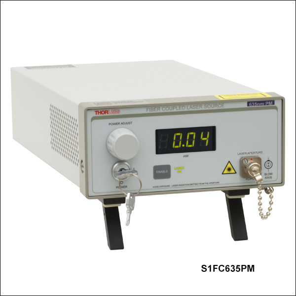
ズーム- 出力波長:635 nm
- FC/PCシングルモード偏波保持ファイバーインターフェイス
- 最大出力:2.5 mW
- ファイバーパッチケーブルは別売りでご用意
- 偏波保持ファイバのスロー軸がFC/PCバルクヘッドコネクタのナローキーにアライメント
- 可視域のカスタム波長もご提供可能(当社までお問い合わせください)
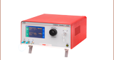
こちらの偏波保持ファイバ出力型レーザ光源は、ピグテール付きのファブリペローレーザがベンチトップ型ユニットに納められています。半導体レーザにはシングルモード偏波保持ファイバが結合されており、ユニット前面パネルに設置されたFC/PCバルクヘッドから出力されます。半導体レーザの偏光軸が偏波保持ファイバのスロー軸と合致するようファイバーアライメントが維持されています。また、偏波保持ファイバのスロー軸はベンチトップ型ユニット前面パネルのFC/PCバルクヘッドコネクタのナローキーにも合うように設計されています。当社では前面パネルのバルクヘッドに接続するための偏波保持ファイバーパッチケーブルをご用意しております。接続損失を抑えるためにはレーザ装置内部で使用されているファイバと同じ種類のファイバーパッチケーブルを使用することをお勧めいたします。内部で使用されているファイバについては「仕様」タブをご覧ください。後方反射によるノイズを低減するために、レーザ光源に接続されたFC/PCコネクタに対して、ハイブリッド型のFC/PC-FC/APCケーブルのご使用をお勧めいたします。
前面パネルには、出力値(mW)が表示できるディスプレイ、ON/OFF キー、Enableボタン、そしてレーザ出力調整ノブがあります。背面パネルには、外部からの電圧信号によって半導体レーザの駆動電流を制御するための入力端子とインターロック用リモートコントロール入力端子が付いています。
注:この光源に他のファイバを接続したり、取り外したりする際には、レーザ出力をOFFにしてください。