 Products Home / 半導体レーザ用電流コントローラ(LDドライバ)、温度コントローラ、LDマウント / 電流コントローラと温度コントローラ一体型ドライバ / コンパクト型半導体レーザードライバ、温度コントローラおよびバタフライ型マウント付き
コンパクト型半導体レーザードライバ、温度コントローラおよびバタフライ型マウント付き
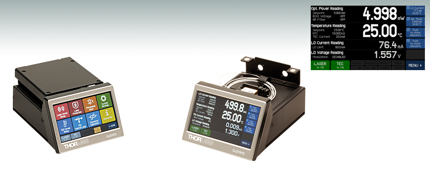
- Compact, All-in-One Current Source, Temperature Controller, and Mount
- Compatible with Thorlabs' Butterfly Lasers
- Touch Screen Controlled and Remotely Programmable
CLD1015
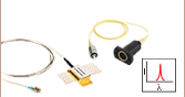
Drives Butterfly
Packaged Laser Diodes
CLD1015
Shown with a
Butterfly Laser
(Not Included)
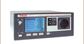
Main Operation Panel in Constant Power
Operating Mode


Please Wait

Click to Enlarge
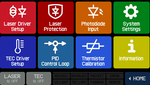
Figure 1.2 ホーム画面
Click to Enlarge
Figure 1.1 メニュー画面
特長
- 当社のピグテール付きバタフライ型レーザ用マウント付き
- 定電流モードまたは定光出力モードで動作
- ローカル制御はタッチパネル式GUIで、リモート制御はUSB経由
- 4 Vで1.5 Aまでのレーザ駆動電流に対応
- TEC電流は3.0 Aまで供給
- 111 mm x 73.5 mm x 169.9 mmのコンパクトサイズ
Click to Enlarge
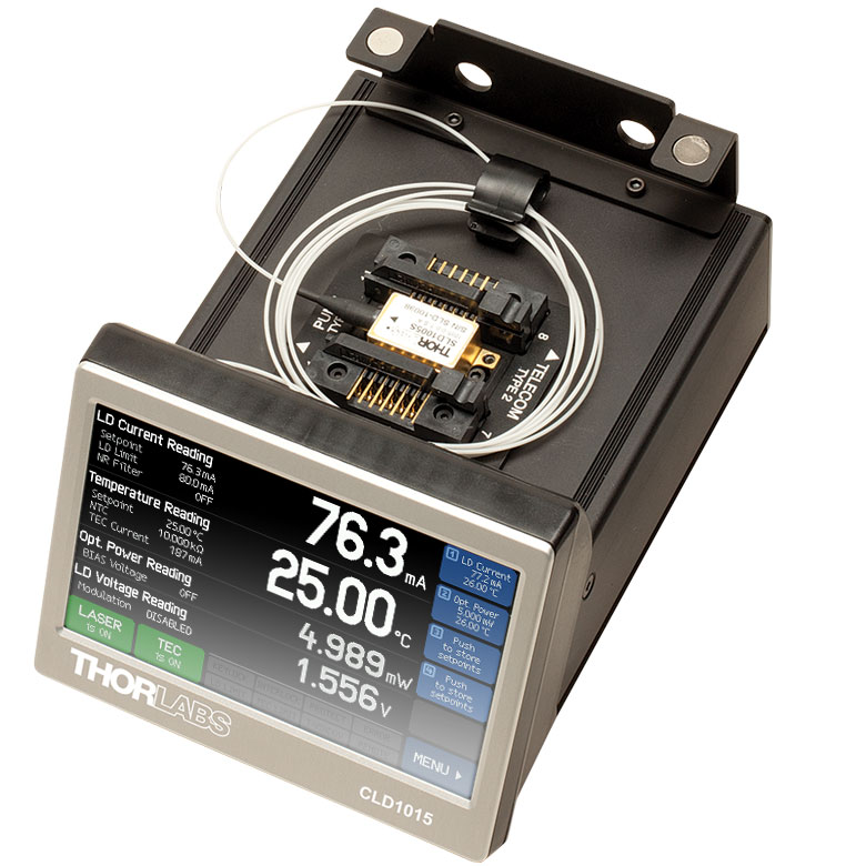
Figure 1.3 バタフライ型レーザを取り付けたCLD1015
半導体レーザ&温度コントローラCLD1015は、ピグテール付きバタフライ型半導体レーザを駆動および冷却するために設計されたドライバーパッケージです(詳細は「ピン配列」タブ参照)。 レーザーマウントが内蔵されているので、携帯性ならびに機械的安定性に優れています。 CLD1015は、タイプ1、タイプ2両方のバタフライパッケージ形状の、ファイバ出力型レーザ、スーパールミネッセントダイオード、レーザ光増幅器に対応します。 駆動電流は最大1.5 Aで、当社のピグテール付きバタフライ型半導体レーザ全てに対応可能です。一体型の構造により、半導体レーザの温度は0.005°Cに保たれ、安定性の高い出力と長い寿命をもたらします。 またソフトスタートモード、電流/温度リミット値設定、および外部インターロック機構などの安全機能に加え、半導体レーザードライバCLD1015には、切り替え可能なノイズ低減フィルタや変調入力端子も装備されています。
半導体レーザードライバは、内蔵型4.3インチのカラータッチパネル画面から制御します。タップに即時に反応するので、レーザ出力のパラメータの調整、微調整、ならびに最適化が容易です。 動作パラメータは直感的なメニューシステムから設定します。ホーム画面から移動に際し、2回以上タップする必要はありません。 「画面表示」のタブをご参照いただくと、インターフェイスのスクリーンショットがご覧いただけます。 ユニットの背面にはmini-USBコネクタがありますが、これを利用すると、LabVIEWやSCPI(Standard Commands for Programmable Instruments)コマンドを含む一般的なプログラミング言語でリモート制御が可能となります。 選択可能なオプションについては「ソフトウェア」タブ内をご参照ください。CLD1015をレーザの駆動にお使いの場合は、すべてのパラメータが最大定格値の範囲内で設定されていることをご確認ください。
| Compact LD Driver, TEC, and Mount Selection Guide | ||
|---|---|---|
| Item # | Accepted Package Configurations | Max Drive Current |
| CLD1015 | Type 1 and Type 2 Butterfly Packages | 1.5 A (@ 4 V) |
| CLD1010LP | TO Can Packages with an A, D, E, or G Pin Code | 1.0 A (@ 7 V) |
| CLD1011LP | TO Can Packages with a B, C, or H Pin Code | 1.0 A (@ 8 V) |
組立後のデバイスの寸法は111 mm x 73.5 mm x 169.9 mmとコンパクトで部品が密集したセットアップでの使用に適しています。 ユニットの背面にあるポートはファイバの入出力に適しており、当社のFC-FCジョイント(アダプタ)(別売り)にも接続できます。 2つの穴は角フランジ形ジョイント(アダプタ)に対応し、もう2つはD型穴付きFCジョイント(アダプタ)に対応します。 磁力で閉じる蓋がレーザーパッケージをユニット内に密閉し、粒子状物質等研究室内の危険からレーザーパッケージを守ります。M6のボルトが使用可能な2個の取付け用クリップが付属しているので、蓋をブレッドボードに固定するためにお使いください。
ドライバーソフトウェア、ならびにSCPI、LabVIEW™、Visual C++、Visual C#、Visual Basicのプログラミングリファレンスガイドについては「ソフトウェア」のタブをご覧ください。
注: 半導体レーザードライバは、ローカル制御はタッチパネル画面で、リモート制御はUSB経由で行うことができます。 タッチパネル画面からローカル制御した場合、半導体レーザードライバの分解能は画面ディスプレイの解像度によって制限されます。よって最大分解能は、リモート制御により得ることができます。 USBを介してアクセスできるコマンドセット(例えばLabVIEWやSCPI(Standard Commands for Programmable Instruments)を利用すると、Table 2.3に記載されている分解能が実現できます。
| Table 2.1 Laser Diode Driver Specifications | ||||
|---|---|---|---|---|
| Via Front Panela | Via Remote Controla | |||
| Current Control (Constant Current Mode) | ||||
| Control Range | 0 to 1.5 A | |||
| Compliance Voltage | > 4 V | |||
| Resolution | 100 µA | 50 µA | ||
| Accuracy | ±(0.1% + 500 µA) | |||
| Noise and Ripple (Typical; 10 Hz to 10 MHz, RMS; @ 3.3 Ω Load, Current <1.2 a="" strong=""> | 10 µA without Noise Reduction Filter 5 µA with Noise Reduction Filter | |||
| Drift (24 Hours) | < 50 µA @ 0 - 10 Hz in Constant Ambient Temperature | |||
| Temperature Coefficient | < 50 ppm/°C | |||
| Current Limit | ||||
| Setting Range | 1 mA to 1.5 A | |||
| Resolution | 100 µA | 50 µA | ||
| Accuracy | ±(0.12% + 800 µA) | |||
| Photodiode Input | ||||
| Photocurrent Measurement Rangesb | 0 to 2 mA (Low) 2 to 20 mA (High) | |||
| Photocurrent Resolutionb | 100 nA (Low) 1 µA (High) | 70 nA (Low) 700 nA (High) | ||
| Photocurrent Accuracyb | ±(0.08% +0.5 µA) (Low) ±(0.08% +5 µA) (High) | |||
| Photodiode Reverse Bias Voltage | 0.1 to 6 V | |||
| Photodiode Input Impedance | ~0 Ω (Virtual Ground) | |||
| Power Control (Constant Power Mode) | ||||
| Photocurrent Control Rangesb | 0 to 2 mA (Low) 0 to 20 mA (High) | |||
| Laser Voltage Measurement | ||||
| Resolution | 1 mV | 200 µV | ||
| Accuracy | ±(1% + 40 mV) | |||
| Laser Overvoltage Protection | ||||
| Trip Voltage (Typical) | 4.2 V | |||
| Modulation Input | ||||
| Input Voltage | ±10 V | |||
| Input Impedance | 10 kΩ | |||
| 3 dB Small Signal Bandwidth (Constant Current Mode) | DC to 250 kHz without Noise Reduction Filter DC to 7.5 kHz with Noise Reduction Filter | |||
| Modulation Coefficient (Constant Current Mode) | 150 mA/V ± 5% | |||
| Modulation Coefficient (Constant Power Mode)c | 200 µA/V ± 5% (Low) 2 mA/V ± 5% (High) | |||
| Table 2.2 TEC Specifications | ||
|---|---|---|
| Via Front Panela | Via Remote Controla | |
| TEC Current Output | ||
| Control Range | -3.0 to +3.0 A | |
| Compliance Voltage | > 4.7 V | |
| Maximum Output Power | > 14.1 W | |
| Resolution | 1 mA | 100 µA |
| Accuracy | ±(0.2% + 20 mA) | |
| TEC Current Limit | ||
| Setting Range | 5 mA to 3.0 A | |
| Resolution | 1 mA | 100 µA |
| Accuracy | ±(0.2% + 20 mA) | |
| NTC Thermistor Sensors | ||
| Resistance Measurement Range | 300 Ω to 150 kΩ | |
| Control Rangeb | -55 °C to +150 °C (Max) | |
| Temperature Resolution | 0.01 °C | |
| Resistance Resolution | 1 Ω | |
| Accuracy | ±(0.1% + 1 Ω) | |
| Temperature Stabilityb (24 Hours) | < 0.005 °C (Typical) | |
| Temperature Coefficient | < 5 mK/°C | |
| Temperature Window Protection | ||
| Setting Range | 0.01 °C to 100.0 °C | |
| Protection Reset Delay | 0 to 600 s | |
| Table 2.3 General Specifications | |
|---|---|
| Interface | |
| USB 2.0 | Compliant with USBTMC/USBTMC USB488 Specification Rev. 1.0 |
| Protocol | SCPI-Compliant Command Set |
| Supplied Drivers | VISA VXI pnp™, MS Visual Studio™, MS Visual Studio.net™, LabVIEW™, LabWindows/CVI™ |
| General Data | |
| Safety Features | Interlock, Keylock Switch, Laser Current Limit, Soft Start, Short Circuit when Laser Off, Laser Overvoltage Protection, Over Temperature Protection, Temperature Window Protection |
| Display | 4.3" LCD TFT, 480 x 272 Pixels |
| Socket for Laser, Photodiode, NTC, TEC | Compatible with Butterfly Type 1 (Pump) and Butterfly Type 2 (Telecom) |
| Connector for DC Power Input | 2.0 mm Center Pin Connected to + |
| Connector for Modulation Input | SMA |
| Connector for Interlock & Laser On Signal | 2.5 mm Mono Phono Jack |
| Connector for USB-Interface | USB Type Mini-B |
| Chassis Ground Connector | 4 mm Banana Jack |
| Desktop Power Supply, Line Voltage, Line Frequency | AC: 100 to 240 V ± 10%, 47 to 63 Hz DC: 12 V ± 5% / 3.5 A |
| Maximum Power Consumption | 40 VA |
| Operating Temperature | 0 to +40 °C |
| Storage Temperature | -40 to +70°C |
| Warm-up Time for Rated Accuracy | 30 min |
| Weight (with Power Supply) | 1.0 kg |
| Weight (without Power Supply) | 0.75 kg |
| Dimensions without Operating Elementsa (W x H x D) | 111 mm x 73.5 mm x 153.3 mm (4.37" x 2.9" x 6.04") |
| Dimensions with Operating Elementsa (W x H x D) | 111 mm x 73.5 mm x 169.9 mm (4.37" x 2.9" x 6.69") |
コントローラーインターフェイス
この半導体レーザーコントローラのインターフェイスは、フラットなメニュー階層のソフトであるため、調整が必要なパラメータを簡単に見つけることができます。
| 定電流モードの場合のホームスクリーン | 定光出力モードの場合のホームスクリーン | ||
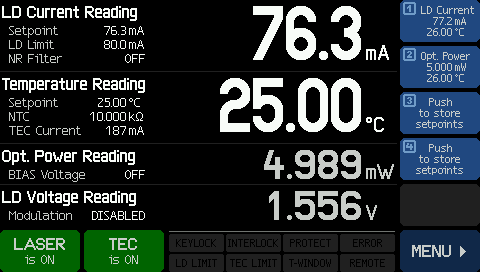 Click to Enlarge | 定電流モードでは、ホームスクリーンのとき、半導体レーザの電流と温度が大きく表示され、その設定値が画面に表示されます。モニタ用PDが測定した光出力値も表示されます。メモリ内には、最大で4つの設定値の組み合わせが保存できます。 | 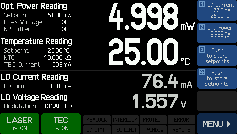 Click to Enlarge | 定光出力モードでは、ホームスクリーンのとき、レーザの光出力の値と半導体レーザの温度が大きく表示されます。 半導体レーザの電流値も表示されます。 |
| 設定値入力 | メニュースクリーン | ||
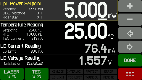 Click to Enlarge | いずれの設定値も簡単に変更できます。 変更したい数値をタップするだけで、右側にボタンが表示されて数値の変更が可能になります。 調整中には、現在のパラメータが表示されます。 | Click to Enlarge | CLD1015のソフトウェアは、直観的に使える2階層のメニュー構造を持ちます。 このメニューでは、レーザとペルチェ素子(熱電冷却素子)に関連した設定が全て実行できて、その他にもシステム関連の設定ができます。 |
半導体レーザーコントローラ用ソフトウェア
下図のダウンロードボタンのリンク先には、VISA VXI pnp™、MS Visual Studio™、MS Visual Studio.net™、LabVIEW™および LabWindows/CVI™のドライバ、ファームウェア、ユーティリティ、そしてITC4000シリーズのレーザーコントローラと、LDC4000シ リーズのレーザーコントローラ、CLD1000 シリーズの小型半導体レーザーコントローラ、TED4000シリーズのTECコントローラに関連したサポートドキュメントがあります。
ソフトウェアのダウンロードページには、SCPI、LabVIEW、Visual C++、Visual C#、Visual Basicを使用して様々なコントローラを結合させるリファレンスプログラミングノートもご用意しております。詳細やリンク先についてはソフトウェアダウンロードページの「Programming Reference」のタブをご覧ください。
ソフトウェア
バージョン 3.1.0 (April 11, 2014)
Programming Reference
バージョン3.3 (April 8, 2015) - SCPI Commands
バージョン1.0 (June 16, 2015) - LabVIEW, Visual C++, Visual C#, Visual Basic
これらのソフトウェアパッケージは、LabVIEWのバージョン8.5以降をサポートします。お手元のLabVIEWがそれ以前のバージョンの場合は、当社にご相談ください。
CLD1015に取り付け可能なバタフライ型半導体レーザ
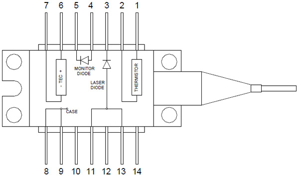
半導体レーザードライバ&温度コントローラCLD1015は、タイプ1の励起用半導体レーザとタイプ2の通信用半導体レーザに対応します。 使用したいバタフライ型パッケージとの接続性を確認するには、下のピン配列図をご参照ください。 CLD1015の内部には、タイプ1とタイプ2のレーザを装着する際の正しい向きが表示されています。
タイプ1:励起用半導体レーザ
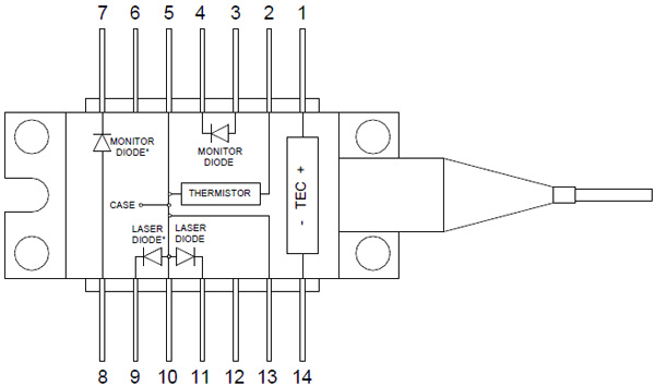
| Pin | Connection | Pin | Connection |
|---|---|---|---|
| 1 | TEC+ (Thermoelectric Cooler) | 8 | Monitor Diode Anodea |
| 2 | Thermistor | 9 | Laser Diode Cathodeb |
| 3 | Monitor Diode Anodea | 10 | Laser Diode Anode |
| 4 | Monitor Diode Cathodea | 11 | Laser Diode Cathodeb |
| 5 | Thermistor | 12 | No Connection |
| 6 | No Connection | 13 | Ground |
| 7 | Monitor Diode Cathodea | 14 | TEC- (Thermoelectric Cooler) |
タイプ2:通信用半導体レーザ
| Pin | Connection | Pin | Connection |
|---|---|---|---|
| 1 | Thermistor | 8 | Ground |
| 2 | Thermistor | 9 | Ground |
| 3 | Laser Diode Cathode | 10 | No Connection |
| 4 | Monitor Diode Anode | 11 | Laser Diode Anodea |
| 5 | Monitor Diode Cathode | 12 | No Connection |
| 6 | TEC+ (Thermoelectric Cooler) | 13 | Laser Diode Anodea |
| 7 | TEC- (Thermoelectric Cooler) | 14 | No Connection |
PIDの基礎
PID回路は制御ループフィードバックコントローラとしてよく用いられており、さまざまなサーボ回路として広く使われています。 PIDとは、それぞれ比例(Proportional)、積分(Integral)、微分(Derivative)の頭文字で、PID回路の3つの制御設定を表しています。 サーボ回路の役割は、システムを長時間所定値(目標値)に保持することです。 PID回路は、出力を目標値に保持するため、主に目標値と出力値の差をエラー信号として発生させることにより、システムをアクティブ制御しています。 3つの制御は、時間依存型エラー信号に関連しています; 端的に言うと、次のように考えることができます。 比例は出力値のエラー、積分は過去の累積エラー、微分はエラーの予測によっています。 各制御の結果は、その後回路の電流を調整する加重和にフィードされます(u(t))。 この出力は制御デバイスへ送られ、その値は回路へとフィードバックされ、回路の出力を目標値に到達させ保持するようアクティブ安定化の処理が行われます。 以下のFigure 101Aは、PID回路の動作を簡略化したものです。 システム要求や要件によって、サーボ回路に1つもしくは複数の制御を使用することができます(例: P、I、PI、PD、PID)。
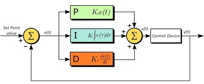 Figure 101A PID制御のブロック線図
PID回路の適正な制御設定によって、最小限のオーバーシュート(目標値超過)とリンギング(目標値振動)で、素早い応答速度を実現できます。 ここで半導体レーザの温度安定化に用いられる温度サーボを例にとってみましょう。 PID回路は、最終的には熱電冷却素子(TEC)への電流を自動制御します(多くの場合FET回路上のゲート電圧の制御を通して行われます)。 この例では、電流は操作変数(MV)とします。 サーミスタは半導体レーザの温度モニタとして用いられ、サーミスタにかかる電圧を処理変数(PV)とします。 目標値(SP)の電圧は指定の温度に対応して設定します。 エラー信号e(t)は、SPとPVの差分を表します。 PIDコントローラはエラー信号を発生し、目標値に到達するようMVを変更させます。 例えばもし、e(t)の状態が半導体レーザの過熱を示せば、回路はTECを通してさらに電流を流すよう促します(比例制御)。 比例制御はe(t)に比例するので、半導体レーザを十分な速度で冷却できないかもしれません。 その場合、累積エラーから判断し、目標値へ到達させようと出力を調整し、回路はTECを介してさらに電流量を増加させます(積分制御)。 SPに到達すると(e(t)が0に近づくと)、回路はSPに達するのを見越してTECを通して電流を減少させます(微分制御)。
PID回路は適切な制御を保証するものではないことにご注意ください。 不適切なPID制御の設定は、回路を著しく振動させたり、制御の不安定を引き起こす可能性があります。 正しい動作は、PIDの適正な調整によって得られます。
PID理論
PID制御回路u(t)の出力を得る方程式は以下となります。
Kp= 比例利得
Ki = 積分利得
Kd =微分利得
e(t)=SP-PV(t)
ここから制御ユニットは数学的定義によって定義づけることができ、個々の制御についてもう少し詳しく考察することができます。 比例制御は、エラー信号に比例します。これは、回路が発生させたエラー信号に対する直接的な応答です。
より大きな比例利得は、より大きな変化をエラーへの応答にもたらし、コントローラがシステムの変化に応答できる速度に影響を与えます。 比例利得の値が高いと回路の応答を素早く行えますが、あまりに高い場合は、SP値に対して振動を引き起こしてしまいます。 値が低すぎる場合は、回路はシステム変更への応答性が悪くなります。
積分制御は、比例利得よりさらに1段階ステップが進み、エラー信号の大きさだけでなく、エラーの期間にも比例しています。
積分制御は、比例制御のみによる定常誤差を除去するとともに、回路の応答速度向上に非常に高い効果をもたらします。 積分制御は、未修正の過去のエラーを合計し、エラーにKiを乗算することで、積分応答を出します。 従ってわずかな継続エラーに対しても、大規模な集積積分応答を実現することが可能です。 しかしながら、積分制御の高速応答に起因して、高い利得値による目標値の著しい超過が生じ、振動と不安定性を引き起こします。 低すぎる場合、回路のシステム変更への応答速度が著しく低下します。
微分制御は、比例制御および積分制御から予測される目標値超過とリンギングを低減させます。 回路が時間の経過とともにどう変化しているか(エラー信号の微分から判断)素早く決定し、Kdを乗算することで微分応答を出します。
比例や積分制御と異なり、微分制御は回路の応答を減速させます。 そのため、積分制御や比例制御によって引き起こされた振動を抑制したり、超過を部分的に補うことができます。 高い利得値は回路の応答性にかなりの減速を生じさせ、ノイズや高周波振動が発生しやすくなります(回路が迅速に応答するには低速すぎるため)。 低すぎると、回路はSP値を超過する傾向にあります。しかしながら、SP値を著しく超過するケースは避けなければならず、そのためより高い微分利得(より低い比例利得とともに)が用いられます。 Table 101Bは、個々のパラメータの利得の増加による影響を示しています。
| Table 101B PID Gain Parameter Effects | |||||
|---|---|---|---|---|---|
| Parameter Increased | Rise Time | Overshoot | Settling Time | Steady-State Error | Stability |
| Kp | Decrease | Increase | Small Change | Decrease | Degrade |
| Ki | Decrease | Increase | Increase | Decrease Significantly | Degrade |
| Kd | Minor Decrease | Minor Decrease | Minor Decrease | No Effect | Improve (for small Kd) |
チューニング
通常、適切なサーボ制御を得るために、P、I、Dの利得値は個々で調整する必要があります。 どのシステムに対してもどの値にするべき、といった決まった一連のルールがあるわけではありませんが、基本手順に沿ったチューニングは各々のシステムや環境に合わせるのに役立ちます。 概して、PID回路はSP値の超過をわずかに起こし、その後SP値に到達させるため素早く減衰するようにします。
手動による利得設定のチューニングは、PID制御設定において最もシンプルな方法です。 しかしながらこの手順はアクティブで行われ(PIDコントローラがオンとなり、システムに正しく接続されている)、完全に設定するには多少の経験を要します。 PIDコントローラを手動で調整するには、まず始めに積分および微分利得を0に設定します。 出力に振動が現れるまで、比例利得を上げてください。 比例利得はこの値の約半分の値に設定します。 比例ゲイン利得設定後は、任意のオフセットがシステムに合わせた適切なタイムスケールに修正されるまで積分利得を上げてください。 上げすぎた場合は、SP値の著しい超過と回路の不安定性が引き起こされます。 積分利得が設定されたら、次に微分利得を上げてください。 微分利得はオーバーシュートを軽減し、システムを迅速にSP値へ収束させます。 微分利得を上げすぎると、大幅な超過が生じます(回路の応答が低速すぎるため)。利得設定を試行することにより、システムが変化へ素早く応答し、SP値の振動を効率よく減衰させるといった、PID回路の性能を最大限にすることができます。
| Table 101C Control Circuit Gains | |||
|---|---|---|---|
| Control Type | Kp | Ki | Kd |
| P | 0.50 Ku | - | - |
| PI | 0.45 Ku | 1.2 Kp/Pu | - |
| PID | 0.60 Ku | 2 Kp/Pu | KpPu/8 |
手動によるチューニングは非常に効果的なPID回路の設定方法ですが、ある程度の経験とPID回路および応答についての理解を必要とします。 PIDチューニングのためのZiegler-Nicholsメソッドは、もう少し体系的な手引きとなっています。 再び、積分利得と微分利得をゼロ値にセットしてください。 比例利得を回路が振動するまで上げます。 この利得をレベルKuと呼びます。 振動はPuの期間です。 個々の制御回路の各利得はTable 101Cに示しています。
なお、デジタルサーボコントローラDSC1などのデバイスにZiegler-Nicholsメソッドを使用する場合、積分利得と微分利得をサンプルレートで正規化する必要があることにご留意ください。そのためには、表から求めた積分利得をHz単位のサンプルレートで割り、微分利得にHz単位のサンプルレートを乗じる必要があります。
Video Insights(How-to動画集):ピグテール付き、バタフライパッケージ型半導体レーザのセットアップ
バタフライパッケージ型の半導体レーザは、CLD1015をはじめとするTECコントローラと電流コントローラ付きのマウントに取り付けることにより、コンパクトなパッケージで精密な制御が可能となります。このマウントにより、レーザの取り扱いはより簡単で安全になりますが、レーザをマウントに取り付ける際には様々な注意が必要です。こちらの動画では半導体レーザの取り付けや設定に関するガイドとなっています。始めに様々な関連部品について説明し、温度制御、最大電流リミット設定など、レーザ操作に必要な手順をご紹介します。
そのほかにも実験室でお使いいただけるヒント、工夫や方法などの動画がこちらからご覧いただけます。また、ウェビナーでは、当社製品を実用的かつ理論的にご紹介しています。
| Posted Comments: | |
Colin Kingsley
(posted 2025-11-07 14:36:45.357) I'm building a portable instrument with a CLD1015 in it, and had planned on fastening it to a 0.5" aluminum breadboard with the supplied mounting clips. However, the clips, and mounting scheme in general, don't seem very secure - and certainly not as well designed as most of the Thorlabs parts I've been purchasing recently. It's working, for now; but I think this mounting interface would really benefit from a redesign. Even something as simple as slightly lengthening the mounting clips (and the slotted hole in them) would at least make the current mounting scheme more secure; but ideally a more thorough redesign would be great. If there were a place to add holes to directly secure it with 1/4-20 SHCS to a breadboard, that would be spectacular. jjadvani
(posted 2025-11-10 03:34:29.0) Dear colin, thank you for your feedback. We truly appreciate your feedback, as it helps us continually improve our products and services. I’ll be sure to share your comments with our development team for consideration in future updates SHI YIHUAN
(posted 2025-07-16 16:43:31.303) We are currently using your laser diode driver in our system to operate several types of LDs. However, we have encountered the following issue:
When driving laser diodes that require high operating current, the driver consistently triggers an overvoltage protection fault and shuts down, regardless of the actual current level we set. In contrast, the driver works well with low-voltage DFB lasers.
We would like to ask:
Is the overvoltage trip point adjustable in your driver?
If so, could you please advise how to modify it or provide the necessary technical documentation?
Your assistance would be greatly appreciated, as this issue is currently limiting our testing. jjadvani
(posted 2025-07-16 05:00:35.0) Dear Shi, thank you for contacting Thorlabs. The compliance voltage for the CLD1015 is 4.2 V; if your laser requires more than that, the laser output will be turned off automatically to prevent device damage. I'll contact you directly to provide additional support. Mark Denninger
(posted 2025-07-09 12:08:25.637) When mounting a butterfly package using the four M2x5 screws, what is the recommended torque to apply? Or even better: what is the strength class of the supplied screws? I am currently using 0.16 Nm and would like to know if this is sufficient?
Best regards
Mark hchow
(posted 2025-07-10 06:03:01.0) Dear Mr. Denninger, thank you for your feedback. We do not have specific data with respect to how much torque one should use when mounting a butterfly package onto the butterfly laser mount of the CLD1015. That being said, you should not over tighten your laser diode. Simply apply enough torque such that the screws do not come loose. Walter Conrad
(posted 2025-05-28 13:56:56.447) Hello. It appears that the CLD1015 Laser Diode Driver is furnished with a mounting bracket. Is the bracket removable? hchow
(posted 2025-05-30 04:49:32.0) Dear Mr. Conrad, yes the mounting brackets are in fact removable. Thank you for your feedback. user
(posted 2025-05-22 14:12:34.717) 我想咨询一下cld1015是否可以周期性的控制通断,变化的周期是10Mhz。 hkarpenko
(posted 2025-05-23 09:00:38.0) Dear customer,
thank you for your feedback. The CLD1015 features a modulation input port, allowing the drive current to be controlled via an external voltage signal up to 250kHz. I will contact you directly to discuss your application in detail. user
(posted 2024-12-04 12:07:37.77) 您好,请问在正常工作状态下,1015型的泵浦突然不出光了,是碟片的问题还是驱动的问题呢,或者说影响的可能性有哪些,应该怎么进行排查? hchow
(posted 2024-12-05 05:39:10.0) 感谢您联系我们。您当地的技术支持团队成员将直接与您联系以解决您的问题。 Max A
(posted 2024-09-24 14:06:06.79) Are those CLD1015 compatible with BOA1550P - C-Band Booster Optical Amplifier? fmortaheb
(posted 2025-03-12 08:45:46.0) Dear Max, Thank you for providing feedback. You can use the CLD1015 with BOA1550P. When using the BOAs with the CLD1015, use the orientation for type 1 pin configurations. D Sahin
(posted 2024-08-26 10:17:12.48) Hi,
I am using this driver to drive a type-2 butterfly packaged DFB under external modulation and I am observing some exponential dependence on the fall edge of the square pulse. I observed the same issue on the rising edge which I was able to adjust the current to get rid of but I am unable to get rid of the falling edge exponential dependence. It seems to be coming from the driver as whatever frequency I use (500Hz to 1kHz) and various fall edge decay time (0 to 50us), I see the very similar time dependence about ~230 us. Any leads on why I might be seeing that? I already tried enabling. disabling noise reduction filter and has no impact.
Thanks, Dee hkarpenko
(posted 2024-08-28 10:35:32.0) Dear Dee,
thank you very much for your feedback. Indeed the absolute falltime of the signal can be significantly higher then the rise time. However the 3dB fall and rise times should be in the same range as specified in the data sheet. For troubleshooting I would appreciate if you can share screenshots of your scope with us to have a better understanding of the issue. I will contact you directly to discuss this issue further with you. John Houlihan
(posted 2024-08-13 16:24:46.857) Hello, my goal is to write custom software for the CLD1015 on a Linux operating system. Do you have Linux drivers that you can provide to me? hkarpenko
(posted 2024-08-14 09:27:31.0) Dear John,
thank you very much for your feedback.
Unfortunately we don´t support linux and cannot provide drivers for it. Thus you would have to work with windows to operate our laser drivers. You can download them directly on our webpage under the tab "Software". Loïc Laplatine
(posted 2024-07-09 15:28:58.263) Dear Throlabs Team,
When I change the laser diode current limit, most of the time it is not saved after restarting the CLD1015... Is there a trick to save this safety parameter?
Regards, jjadvani
(posted 2024-07-10 07:13:57.0) Dear Loic, Thank you for your feedback. I will contact you directly to discuss your issue. Gareth Lees
(posted 2024-01-16 15:16:40.723) It would be a great addition to this product if it could support 10pin mini butterfly packages. A number of pump lasers manufacturers are using these 10pin mini butterfly packages over the 14pin packages.
If this is already an option please let me know.
Best regards
Gareth dpossin
(posted 2024-01-17 09:08:07.0) Dear Gareth,
Thank you for your feedback and the expressed suggestions. We will take that into our discussion regarding the successor of the CLD1015. Anna Malekmohamadi
(posted 2023-11-05 11:05:35.413) Daer Thorlabs,
We have one of your CLD1015 driver that unfortunately does not work properly. The problem is, we insert the diode for the very first time in this driver, and after turning on the device and setting the current limit, when we turn on the "laser on" button, the LD voltage reading amount increases continuously and quickly, that in a second driver turns off the laser and shows an error that laser should be off for protection. Could you please help us to know what is the problem with this device?
Deutsches elektronen synchrotron DESY hkarpenko
(posted 2023-11-08 08:19:30.0) Dear Anna,
thank you for your request.
This issue can have several reasons and depends on the settings made in the software. I will contact you directly to discuss this further with you. Menachem polak
(posted 2023-01-16 03:44:53.61) Hello,
we are interested in using the CLD1015 with Photodigm's PH852DBR butterfly pigtailed laser diode. https://www.photodigm.com/products/852-nm-laser-diode
so in terms of electrical interfaces, I checked and
it seems to be fully compatible(please correct me if I'm wrong). In terms of mechanical interface the only slight difference I saw in compares to DBR852PN is that the height of the PH852DBR from its baseplate to the butterfly pins is 5 mm versus the DBR852PN's 5.5 mm. and the second mechanical difference is that the height of the PH852DBR from its baseplate to the center of the waveguide is 4.9 mm versus DBR852PN's 6 mm.
will we have problems mechanically wise or is it okay?
Thanks hchow
(posted 2023-01-17 07:23:39.0) Dear Mr. Polak, thank you for your feedback. I have taken a look at the webpage you posted, however, I was unable to find the dimensions of the Photodigm's PH852DBR. The pins on the ZIF socket, where the butterfly laser diode goes onto can be depressed slightly, definitely more than the 0.5 mm difference between the DBR852PN and the PH852DBR. Which means, our CLD1015 laser driver should theoretically work with the third party butterfly laser diode, PH852DBR. I will contact you personally to provide more information. Thank you. Zihao Wang
(posted 2022-11-23 14:33:39.843) Hi there,
We are using the CLD1015 model and would like to use it the drive our laser. The problem is our lasers have two sections that need to apply constant current and reverse biased voltage for each part. We tried to use the MPD pin to provide the voltage but we find one of the MPD pins is connected to the anode of the current source. To make things simple, our laser structure is very similar to EML and do not need the RF signal, just need to provide constant current and voltage. Is that possible to do it in CLD1015 modual? wskopalik
(posted 2022-11-24 04:31:05.0) Thank you very much for your feedback!
The CLD1015 controllers are designed to operate laser diodes with the type 1 and 2 butterfly packages which are shown in the tab “Pin Diagrams”. For other butterfly diode types, we would need to compare the pin configuration to make sure that the diode is compatible.
I will contact you directly to provide further assistance. Jonas M
(posted 2022-11-11 12:17:16.3) Can I block the operator from changing Laser Diode Current Limit to make sure laser output power is not exceeding a certain value? dpossin
(posted 2022-11-11 09:29:55.0) Dear Jonas,
Thank you for your feedback! Unfortunately, there is no such function you are looking for. Aleksey Vasilyev
(posted 2022-10-14 10:47:23.36) We have the problem of connecting more than 3 CDL1015 controllers to the USB hub at the same time. NI MAX became unresponsive and can not detect them.
We did try to use different hubs but the result is always the same. dpossin
(posted 2022-10-17 09:14:17.0) Dear Aleksey,
Thank you for your feedback. I am reaching out to you in order to discuss possible solutions. user
(posted 2022-07-12 21:26:22.843) Can I install ADAFCPM2 mating sleeve on the wall of CLD1015 for fiber coupling purposes? fmortaheb
(posted 2022-07-14 10:21:11.0) Thank you very much for contacting Thorlabs. Yes, you can mount the ADAFCPM2 on the rear panel. Please check the manual, P.74 (https://www.thorlabs.de/_sd.cfm?fileName=21440-D02.pdf&partNumber=CLD1015). user
(posted 2022-06-20 19:26:44.497) I want to use DBR780PN diode laser which has PM Fiber Output with 2.0 mm Narrow Key FC/APC Connector, with the CLD1015. After connecting it to the mating sleeve to the back of the mount what type of fibre one should connect at the output optical port of the CLD1015? Should it be FC/PC or FC/APC? GBoedecker
(posted 2022-06-22 04:47:00.0) Thank you for your inquiry! The CLD1015 has no optical input and output port. You can directly connect the connector of the DBR780PN to your further components. user
(posted 2022-06-15 23:23:04.28) Which model of fibre optic cable of Thorlabs is suitable for taking optical output from the mount CLD1015? wskopalik
(posted 2022-06-16 09:17:35.0) Thank you very much for your feedback.
The CLD1015 drivers can be used with different butterfly laser diodes. These diodes usually already have a fiber installed. The fiber type depends on the properties of the diode (e.g. wavelength, polarization).
If you want to attach an additional fiber to the fiber of the diode, you would need to match the properties of the two fibers. This way you can achieve the best coupling efficiency.
Unfortunately, you did not leave any contact details so I cannot contact you directly. Please feel to contact your local Thorlabs tech support so we can help you with selecting the best fiber. user
(posted 2022-06-15 22:41:16.33) Which model of fibre optic cable of Thorlabs is suitable for taking optical output from the mount? wskopalik
(posted 2022-06-16 09:18:35.0) Thank you very much for your feedback.
The CLD1015 drivers can be used with different butterfly laser diodes. These diodes usually already have a fiber installed. The fiber type depends on the properties of the diode (e.g. wavelength, polarization).
If you want to attach an additional fiber to the fiber of the diode, you would need to match the properties of the two fibers. This way you can achieve the best coupling efficiency.
Unfortunately, you did not leave any contact details so I cannot contact you directly. Please feel to contact your local Thorlabs tech support so we can help you with selecting the best fiber. user
(posted 2022-05-18 19:09:49.807) what is the bandwidth of CLD1015 if one wants to operate the butterfly laser diode in constant power mode? dpossin
(posted 2022-05-20 02:52:52.0) Dear customer,
The modulation bandwidth in constant power mode depends on the fall/rise time of the feedback photodiode in your butterfly laser and the temperature you would like to operate the same at. Therefore we can´t give any specifications on that just for the laser driver. Philip Skochinski
(posted 2021-10-29 08:01:57.96) Hi,
Is a modification available to drive a DIL packaged laser diode?
Thanks,
Phil soswald
(posted 2021-11-03 11:56:54.0) Dear Phil,
thank you for your feedback. I have contacted you directly to discuss your application in more detail. Chia-Chi Liu
(posted 2021-04-29 12:59:55.903) Hi team Thorlabs,
We had purchased several CLD1015 for our butterfly lasers years ago, and things go really well with them.
However, we got a new type 2 butterfly laser recently, which comes with wider pin width (width = 0.75 cm).
Is it possible that we could order an extra ZIF socket (as described in the manual, page 11) with a wider pin sockets?
Thanks! MKiess
(posted 2021-05-04 10:12:32.0) Dear Chia-Chi Liu, thank you very much for your inquiry.
The manual describes how to install the included ZIF socket to use the CLD1015 with either a type 1 pump laser diode or a type 2 DFB laser diode, starting on page 11. It is not recommended to simply install an arbitrary ZIF Socket.
I have contacted you directly for a possible conversion or corresponding custom designs. Y BoH
(posted 2020-12-11 21:33:03.507) It would be very useful to have a version with lower current output (300mA to 500mA will be sufficient) and much better current noise and temperature stability performance. People can use that for driving butterfly DBR/DFB laser diodes for high power fiber amplifier seeding purpose. MKiess
(posted 2020-12-15 06:00:10.0) Thank you very much for this feedback. This helps us to continuously develop and improve our products.
Better temperature stability and current noise can also be achieved with the combination of ITC4001 and the LM14S2 Butterfly Laser Diode Mount. 李 亮
(posted 2020-12-01 10:24:52.983) I bought a DBR795 laser from your company,now I want to modulate it,make a continuous laser to a pulsed laser,I can't do it,looking forward to your reply. wskopalik
(posted 2020-12-01 05:52:14.0) Thank you very much for your inquiry!
The CLD1015 has a modulation input on the back which can be used to apply an external modulation signal to the driving current. The modulation signal can e.g. be created using a signal generator. To enable the modulation input, you need to go to the "Laser Driver Setup" menu and enable the input. Depending on the modulation frequency you can also disable the noise reduction filter in this menu.
I will contact you directly to provide further assistance. YJ Hu
(posted 2020-08-18 17:39:00.47) I want to use constant power mode, it is originally constant current mode. But after I switch to CP mode, both current and power are zero. The laser cannot be turned on. what should I do to set it to CP mode? MKiess
(posted 2020-08-18 09:08:07.0) Hello, thank you very much for your inquiry. When all parameters, corresponding to your laser diode with integrated photodiode, have been entered in the controller settings, you can easily modify the power set point as desired. For this you have to tap on the value to be changed at the home screen an set the desired value.
I have contacted you directly to discuss further details. user
(posted 2020-05-28 03:56:54.75) I would like to drive a superluminescent diode (SLD) in constant current mode (NOT constant power) whilst monitoring its PD current (it has a back facet monitor diode). The reason why I want to see the PD current is because it is proportional to the output power of the SLD and also because it indicates if there are backreflections into the SLD. However, in your screenshots of the LCD of the CLD1015 in constant current mode, there is no display of the PD current.
Is there a way to get the LCD to show the PD current ? wskopalik
(posted 2020-06-02 10:56:23.0) This is a response from Wolfgang at Thorlabs. Thank you very much for your inquiry!
It is possible to display the PD current in constant current mode as well. There is a setting "Use Optical Power for Display" in the "Photodiode Input" menu. If this setting is enabled, you will see the optical power in the display. If it is disabled, you will see the PD current.
I will contact you directly to provide further assistance. Peter Yun
(posted 2020-05-22 10:47:20.6) What is the maxium smapling rate when I use the remote control to read the temperature displayed by the CLD1015?
Thanks in advance! dpossin
(posted 2020-06-02 07:57:56.0) Dear Customer! Thank you for your Feedback. In general the sample rate is limited to the maximum usb data transfer speeds and packages. The sample rate of the thermistor temperature depends on the oscillation period set in the PID CONTROL LOOP panel (depends on the used mount) and is calculated by 64 / oscillation period. So for example the maximum sample rate of the TEC temperature is 320 (at an oscillation period of about 0.2 s). Y Yang
(posted 2020-01-10 11:36:44.853) Can CLD 1015 generate constant current square wave signal by connecting signal generator dpossin
(posted 2020-01-13 07:13:42.0) Dear Customer,
Thank you for your feedback. The CLD1015 can be modulated externally via square wave signals. Just note that the maximum bandwith in the specification refers to sinusoidal modulation thus, the maximum bandwidth for square waves is around 10% of the specified bandwidth. M10619007
(posted 2018-12-05 16:30:05.713) I want to know the full width at half maximum of this light source? wskopalik
(posted 2018-12-06 04:25:03.0) This is a response from Wolfgang at Thorlabs. Thank you very much for your inquiry!
The CLD1015 is only the driver needed to run a laser diode, i.e. it supplies the laser diode and also its TEC element with current. You can install different butterfly laser diodes in the CLD1015, but these are not included. The full width at half maximum e.g. of the emitted spectrum depends on the installed laser diode.
I will contact you directly so we can talk about the laser diode in question. v.t.tenner
(posted 2018-11-29 16:08:48.963) Does this driver contains a fan? wskopalik
(posted 2018-12-06 04:12:06.0) This is a response from Wolfgang at Thorlabs. Thank you very much for your inquiry!
Yes, this driver contains a fan to prevent overheating of the components inside.
I will contact you directly to discuss your requirements in further detail. alexey.kokhanovskiy
(posted 2018-09-19 06:33:17.02) Dear Sir/Mme
1) Is CLD1010LP or CLD1011LP fits TO-56 package? I attached example:
http://www.optilab.com/devices/category/laser_diode/SM_1550_nm_VCSEL_pigtail_with_2.5_Gbps/
2) Is it possible to change a mount for TO package to mount for butterfly package?
With respect,
Alexey Kokhanovskiy nreusch
(posted 2018-09-21 09:10:59.0) This is a response from Nicola at Thorlabs. Thank you very much for your inquiry. Yes, CLD1010LP and CLD1011LP are suitable for TO-56 packages. Unfortunately, we cannot offer to modify CLD1010LP or CLD1011LP to be compatible with butterfly packages as the changes would be too large. michael.woods
(posted 2018-05-25 23:34:01.41) Where is the windows based program for controlling this unit over usb? YLohia
(posted 2018-05-29 09:00:57.0) Hello, unfortunately, we do not currently provide a GUI software for controlling this unit. We do, however, provide drivers and references for controlling this via SCPI commands and LabVIEW/C++/C#/Visual Basic here: https://www.thorlabs.com/software_pages/viewsoftwarepage.cfm?code=4000_Series jsauls
(posted 2016-03-24 13:30:55.593) It is possible to modulate a laser diode with this controller via the USB connection and the provided LabView driver VI's, bypassing the external SMA modulation input? besembeson
(posted 2016-03-25 09:35:01.0) Response from Bweh at Thorlabs USA: You may be able to turn the modulation input on or off, but you will not be able to modulate the laser amplitude. This can only be done through the SMA modulation input. With a different controller such as the ITC4001 (http://www.thorlabs.us/newgrouppage9.cfm?objectgroup_id=4052&pn=ITC4001#4054), and suitable mount (http://www.thorlabs.us/navigation.cfm?guide_ID=35), this will be possible. sascha.liehr
(posted 2015-09-09 11:58:23.017) I like to buy new laser current dirvers and TEC drivers and saw the new CLD1015 system.
My questions is: Is the CLD1015 more stable/precise than an equivalent combination of your LDC220C / TED200C controllers? Did you get any feedabck or have recommendations?
I need to ensure lowest possible temperatue and current drift!
Thank you and best regards
Sascha Liehr shallwig
(posted 2015-09-11 01:51:35.0) This is a response from Stefan at Thorlabs. Thank you very much for your inquiry. For the CLD1015 we specify for the laser diode current driver an accuracy of ±(0.1% + 500 µA) and a drift (24 hours) <50 µA @ 0 - 10 Hz in Constant Ambient Temperature.
For the TEC driver the accuracy is specified with ±(0.2% + 20 mA) and the temperature stability over 24 hours is typically <0.005 °C.
Please note the temperature control range and thermal stability depend upon the physical parameters of the thermistor and the operating temperature, respectively.
For the Benchtop devices we specify following:
LDC220C:
Accuracy: ±2.0 mA
Drift, 24hours: <2 mA @ 0 - 10 Hz typ., at constant ambient temperature
TED200C:
Accuracy: ±10 mA
Temperature Stability: ? 0.002 °C
So the laser diode current driver part of the CLD1015 provides more stable results than the LDC220C but the built in TEC driver has slightly worse specifications. I will contact you directly to discuss in more detail which devices are more suitable for your application. user
(posted 2015-02-12 13:32:54.423) CLD1015: Is it possible to modulate optical output power with frequencies up to 20 MHz? The CLD1011LP seems to have this option via a bias tee interface but the CLD1015 seems only to have a modulation input for frequencies in the kHz range. tschalk
(posted 2015-02-16 12:14:17.0) This is a response from Thomas at Thorlabs. The CLD1015 is not equipped with an additional bias-t like the CLD1010. The laser mount LM14S2 can be used with a bias-t adapter to modulate the diode up to 500MHz. Please contact me at europe@thorlabs.com if you need any further assistance. 1982ariel
(posted 2015-01-11 12:37:29.643) Thorlabs hello,
Please specify if this is a current source or voltage source
Ariel shallwig
(posted 2015-01-12 07:00:35.0) This is a response from Stefan at Thorlabs. Thank you very much for your inquiry.The CLD1015 is like all our laser diode controllers a current source. You set the current to a fixed value within the control range and depending on the laser diode (load resistance) the driver sets the compliance voltage automatically. To make sure a laser diode can be driven by a controller the specified operating voltage has to match with the controllers compliance voltage specifications as well as with the current control range. I will contact you directly to discuss your needs in detail. neil.troy
(posted 2014-03-23 06:16:26.72) Can the display be turned off when controlling remotely? The light from the display will saturate our sensitive measurement. tschalk
(posted 2014-03-25 12:00:26.0) This is a response from Thomas at Thorlabs. Thank you very much for your inquiry. In the System Settings (described in the manual at section 2.5.9 System Settings) you can enable the Auto Dimming function. After 30 sec the display ceases and reactivates with a touch to the panel. doug
(posted 2013-02-12 14:40:11.153) The CLD 1015 would be very attractive if I could re-configure the pin-out, and also remove one side of the zero-force pin holder.
I am using a 7-pin butterfly (i.e. one-sided) with a high-speed modulation K-connector on the other side. So, the fixed pin-out of the current product prevents me from using it. jvigroux
(posted 2012-09-12 13:12:00.0) A reposne from Julien at Thorlabs: Thank you for your feedback! We are really glad we could develop a device that triggered such a positive response! We did put a lot of effort into trying to make this device as versatile as possible as the number of potential applications is very large. The switching noise is indeed the main limitation, which was unfortunately not possible to completely eliminate without compromising the output current. scoleman
(posted 2012-09-11 11:32:30.0) I have had the opportunity to use this device for several weeks now and I am very pleased with it. The interface is the best I have used on any laser controller (in 15 years in this business) and provides a great deal of confidence-inspiring information, at a glance. Nothing is extraneous, the home "page" is wonderful. Error handling is great, changing pinouts is very convenient, and the current source and TEC controller are very powerful, especially considering the size of the unit. For applications requiring modulation/pulsing the unit has significantly more bandwidth than similar controllers. The versatility of this little unit is really impressive and all of the features are intuitive to access. It was clearly designed by people very familiar with operating lasers in real-world situations.
The only limitation I have encountered with it thus far is that some switching noise is evident when making sensitive (DFB phase noise/RIN) measurements. . .but in my opinion this is a reasonable trade given the amount of current the current source can provide in such a small package. This noise is reduced at increased drive current. Also, FYI the mounting screws are metric and wrenches are provided.
All in all I highly recommend this device. jvigroux
(posted 2012-09-05 13:07:00.0) A response form Julien at Thorlabs: Thank you for your feedback! We did try to create device that was at the same time as versatile and easy to use as possible as well as compact, which might lead to the impression that the display is cluttered when one only sees screenshots. We will address this point and replace the pictures in order to give a more accurate feeling about the ease of use of the CLD1015, as Sean already wrote. We would also be happy to send you a loan unit so that you can try it out and hopefully change your mind about the ease of use of this device. sharrell
(posted 2012-09-05 10:25:00.0) Response from Sean at Thorlabs: Thank you for taking the time to share your thoughts on our new butterfly laser diode mount and controller. Based on your feedback, we will be taking new photos of the device which will better show its intended function. This device was created after many discussions with customers who were looking for a compact, easy-to-use unit with advanced control features not available on our other mounts. cbrideau
(posted 2012-09-04 14:29:43.0) When I saw the picture for this I thought Thor was selling a kitchen scale. The screen seems overly complex compared to a simple temperature and current readout and a couple knobs but I suppose there are applications where you want to be able to set every tiny detail relatively quickly. |
半導体レーザーコントローラーセレクションガイド
Table 137Aと137B は、当社の半導体レーザ用コントローラおよびデュアル半導体レーザ/温度コントローラの主な仕様の一覧です。詳しい内容や仕様について、またはご注文の際には表内の型番をクリックしてご確認ください。
| Table 137A Current Controllers | ||||||
|---|---|---|---|---|---|---|
| Item # | Drive Current | Compliance Voltage | Constant Current | Constant Power | Modulation | Package |
| LDC200CV | 20 mA | 6 V | External | Benchtop | ||
| VLDC002 | 25 mA | 5 V | - | Int/Ext | OEM | |
| LDC201CU | 100 mA | 5 V | External | Benchtop | ||
| LD2000R | 100 mA | 3.5 V | - | External | OEM | |
| EK2000 | 100 mA | 3.5 V | - | External | OEM | |
| LDC202C | 200 mA | 10 V | External | Benchtop | ||
| KLD101 | 230 mA | ≤10 V | External | K-Cube® | ||
| IP250-BV | 250 mA | 8 Va | External | OEM | ||
| LD1100 | 250 mA | 6.5 Va | - | -- | OEM | |
| LD1101 | 250 mA | 6.5 Va | - | -- | OEM | |
| EK1101 | 250 mA | 6.5 Va | - | -- | OEM | |
| EK1102 | 250 mA | 6.5 Va | - | -- | OEM | |
| LD1255R | 250 mA | 3.3 V | - | External | OEM | |
| LDC205C | 500 mA | 10 V | External | Benchtop | ||
| IP500 | 500 mA | 3 V | External | OEM | ||
| LDC210C | 1 A | 10 V | External | Benchtop | ||
| LDC220C | 2 A | 4 V | External | Benchtop | ||
| LD3000R | 2.5 A | -- | - | External | OEM | |
| LDC240C | 4 A | 5 V | External | Benchtop | ||
| LDC4005 | 5 A | 12 V | Int/Ext | Benchtop | ||
| LDC4020 | 20 A | 11 V | Int/Ext | Benchtop | ||
| Table 137B Dual Temperature and Current Controllers | |||||||
|---|---|---|---|---|---|---|---|
| Item # | Drive Current | Compliance Voltage | TEC Power (Max) | Constant Current | Constant Power | Modulation | Package |
| VITC002 | 25 mA | 5 V | >2 W | - | Int/Ext | OEM | |
| ITC102 | 200 mA | >4 V | 12 W | Ext | OEM | ||
| ITC110 | 1 A | >4 V | 12 W | Ext | OEM | ||
| ITC4001 | 1 A | 11 V | >96 W | Int/Ext | Benchtop | ||
| CLD1010LPa | 1.0 A | >8 V | >14.1 W | Ext | Benchtop | ||
| CLD1011LPb | 1.0 A | >8 V | >14.1 W | Ext | Benchtop | ||
| CLD1015c | 1.5 A | >4 V | >14.1 W | Ext | Benchtop | ||
| ITC4002QCLd | 2 A | 17 V | >225 W | Int/Ext | Benchtop | ||
| ITC133 | 3 A | >4 V | 18 W | Ext | OEM | ||
| ITC4005 | 5 A | 12 V | >225 W | Int/Ext | Benchtop | ||
| ITC4005QCLd | 5 A | 20 V | >225 W | Int/Ext | Benchtop | ||
| ITC4020 | 20 A | 11 V | >225 W | Int/Ext | Benchtop | ||
当社では製品組み込み用あるいはラックマウントの半導体レーザ電流&温度コントローラ(組み込み用モジュール、PRO8電流コントロールモジュール、PRO8電流&温度コントロールモジュール)もご用意しております。