 Products Home / 半導体レーザ用電流コントローラ(LDドライバ)、温度コントローラ、LDマウント / 組み込み用半導体レーザー(LD)ドライバー/コントローラー / 組み込み用温度コントローラー、SMTまたはTHTパッケージ
組み込み用温度コントローラー、SMTまたはTHTパッケージ

- Compact, Highly Integrated TEC Drivers
- Deliver Current up to ±1.5 A or ±2.0 A to TEC
- Designed for OEM, Custom, and Embedded Systems
- Volume Pricing Available
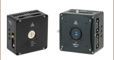
MTD415L
SMT Package for ±1.5 A and
LMT84 IC Temperature Sensor
MTDEVAL1
Evaluation Board for OEM TEC Drivers
21.0 mm
12.4 mm
39.6 mm
21.5 mm
MTD1020T
THT Package for ±2.0 A and 10 kΩ Thermistor
114.5 mm
64.0 mm
MTD415TE
Adapter PCB with Mounted MTD415T
SMT Package
27.0 mm
21.0 mm


Please Wait
| Key Featuresa | |||
|---|---|---|---|
| Item # | MTD415L(E) | MTD415T(E) | MTD1020T |
| Supported Temperature Sensor | LMT84 IC | 10 kΩ Thermistor | |
| Output Current (See Graphs on Specs Tab) | Up to ±1.5 A | Up to ±2.0 A | |
| TEC Compliance Voltage | 4.0 V | 10.0 V | |
| Maximum Output Power (See Graphs on Specs Tab) | Up to 6.0 W | Up to 20.0 W | |
| Noise and Ripple (Typical) | 150 mA (Peak-Peak) or 87 mA RMS | ||
| Temperature Stability (Typical) | 100 mK | ||
| Data Sheet (Click for PDF) | |||
量産および特注等のOEM対応
当社の工場はTECコントローラの大量生産が可能であり、量産計画に沿った製品について、割引価格でのご提供が可能です。
詳細は当社 までお問い合わせください。
Click to Enlarge
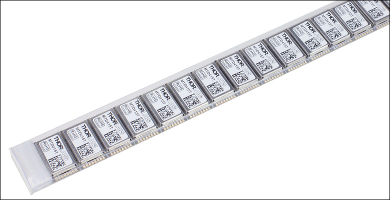
SMTパッケージ入りMTD415シリーズドライバの大量注文については、ICチューブでのお届けも承ります。
特長
- 温度制御用デジタルPIDループ付きTECドライバチップ
- THT、SMT、ドーターボード取り付け済みSMTパッケージの3種類をご用意
- 非常に小さな出力電流ノイズ:<10 mA
- PC制御が可能
- コマンドラインインターフェイスから入力されたシリアルコマンドをUART経由で受信
- GUIにより設定の調整やドライバ性能のモニタが可能(「ソフトウェア」のタブをご覧ください)
- ドライバの設定についての試験および評価用として評価ボードもご用意
用途
- TEC素子を使用する小型のアセンブリに適した製品
- 下記デバイスのアクティブな冷却と温度の安定化
- レーザーモジュール、半導体レーザ
- WDM用ならびにDWDM用半導体レーザ
- エルビウム添加ファイバ増幅器(EDFA)
- フォトディテクタ、フォトダイオード
- 自動試験装置(ATE)
当社では組み込み用途(OEM用途)向けのTECドライバーモジュールをいくつかご用意しております。スルーホール実装(THT)型パッケージとして提供されるMTD1020Tは、コンプライアンス電圧が高いため、5 Ωまでの負荷抵抗に±2.0 Aの最大TEC電流を供給可能です。表面実装(SMT)型パッケージ、および、SMT型ドライバがドーターボード取り付けられたMTD415シリーズは、最大±1.5 AのTEC電流を供給します。典型的な性能グラフや仕様の詳細については「仕様」タブをご覧ください。
いずれの組み込み用TECドライバもデジタル制御ループを使用して電流の出力を調整します。これらのPID制御ループは、PI制御ループを使用するドライバよりも、より速い温度整定時間と優れた安定性をTECドライバにもたらします。真のバイポーラ駆動のため、TEC電流が0 Aに到達するまでの低電流状態において、出力電流に「デッドゾーン」が出現したり、あるいは非線形性を示すことがありません。オンチップの電力段と熱制御ループ回路が、高い熱効率と<10 mAの低い出力電流ノイズを維持するため、外付け部品の必要性が最小限に抑えられています。出力電流はTECにサージ電流が流れ込まないように直接制御されています。またTEC電流リミッタ(調整可能)が付いており、冷却素子のオーバードライブを防止します。
PC制御
このドライバは、UARTデジタルコントロールインターフェイスを通して、PID設定のほか、すべてのシステムパラメータやデジタル測定データに簡単にアクセスできるため、様々なシステムへの組み込みが容易です。TECドライバは、TECドライバのデータシートに記載のプログラミングコマンド(上の表のPDFリンク)、あるいはWindows®システム用GUI(「ソフトウェア」参照)を使用してPCから制御します。このGUIを用いると、特定の熱負荷に対してTECドライバの設定を最適化したり、TECの動作状況を追跡してグラフ表示したりできます。GUIを使用したPIDパラメータの設定例については「PID振動試験」タブをご覧ください。
評価ボード
MTDシリーズのTECドライバの性能評価と、特定の熱負荷への応答性の最適化が必要なお客様のために、評価ボードMTDEVAL1をご用意しております。評価ボードにはUART-USBアダプタが付いており、PCから送られるコマンドを搭載されたドライバに転送することができます。
すべての技術データは、温度23±5°C、相対湿度45±15%(結露なし)の条件下で有効です。
TECドライバ仕様
| Item # | MTD415L(E) | MTD415T(E) | MTD1020T |
|---|---|---|---|
| TEC Current Output | |||
| Maximum Output Current | Up to ±1.5 A (See Graphs Below) | Up to ±2.0 A | |
| TEC Compliance Voltage | 4.0 V | 10.0 V | |
| Maximum Output Power | Up to 6.0 W | Up to 20.0 W | |
| Measurement Resolution | 3 mA (Typical) 8 mA (Max) | 5 mA (Typical) 10 mA (Max) | |
| Measurement Accuracy | ±50 mA | ||
| Noise and Ripple (Typical) | 150 mA (Peak-Peak) or 87 mA RMS | ||
| TEC Current Limit | |||
| Setting Rangea | 0 to 1.5 A | 0 to 2.0 A | |
| Setting Resolution | 1 mA | ||
| Setting Accuracy | ±50 mA | ||
| Temperature Sensor | |||
| Supported Sensor | LMT84 IC Sensor or Similar | 10 kΩ Thermistorb | |
| Maximum Temperature Control Rangec | +5 °C to +45 °C | ||
| Temperature Setting Resolution | 1 mK | ||
| Temperature Measurement Resolutiond | 2 mK (Typical) 10 mK (Max) | 3 mK (Typical) 10 mK (Max) | |
| Absolute Temperature Accuracyc | ±0.5 °C | ||
| Temperature Stability (Typical)e | 100 mK | ||
| Temperature Coefficient | < 20 mK/°C | ||
| Recommended Operating Conditions | |||
| Supply Input Voltage | 4.5 V to 5.5 V | 11.5 V to 12.5 Vf | |
| -20 °C to 60 °C | |||
| 10 Minutes | |||
| Programming Interface | |||
| Type | UART | ||
| Voltage Level | 3.3 V Logic Level; Input 5 V Tolerant | ||
| Data Rate | 115,200 bps; 8 Data Bits, 1 Stop Bit | ||
| Safety Features | |||
| Safety Features | TEC Current Limit Sensor Fault Protection TEC Open Circuit Protection Temperature Setpoint Limit Temperature Window Protection Delay Over Temperature Protection | ||
| Environmental | |||
| Storage Temperature | -40 °C to 100 °C | ||
TECドライバの絶対最大定格
| Item # | MTD415L(E) | MTD415T(E) | MTD1020T | |
|---|---|---|---|---|
| Supply Input Voltage | 4.5 V to 6 V | 11.5 V to 13.0 V | ||
| Supply Input Current | 1.6 A | 2.3 A | ||
| TEC Output Current | -1.5 A to +1.5 A | -2.0 A to +2.0 A | ||
| 4.0 V | 10.0 V | |||
| 6.0 W | 20.0 W | |||
| Power Dissipation | 1.5 W | 4.0 W | ||
(With Respect to Ground Terminal) | VDD | -0.3 V to +6 V | -0.3 V to +13.0 V | |
| TX | - | -0.3 V to +3.6 V | ||
| ENABLE, RX | -0.3 V to (VDD + 0.3 V) | |||
| TEC-, TEC+ | 0.0 V to +13.0 V | |||
| TEMP | -0.3 V to +3.3 V | |||
| Maximum Output Current (STATUS, TX) | 10 mA | |||
| Maximum Input Current (ENABLE, RX) | 10 mA | |||
| Ambient Operating Temperatures | -40 °C to 70 °C | |||
TECコントローラのパッケージの寸法
| Item # | Package Type | Dimensions | Approximate Weight |
|---|---|---|---|
| MTD415L | SMTa | (0.83" x 0.49" 0.12") | 2 g |
| MTD415LE | Daughterboard | (1.56" x 0.85" x 0.55" ) | 4 g |
| MTD415T | SMTa | (0.83" x 0.49" 0.12") | 2 g |
| MTD415TE | Daughterboard | (1.56" x 0.85" x 0.55" ) | 4 g |
| MTD1020T | THTb | (1.06" x 0.83" x 0.41") | 8 g |
MTD415シリーズの典型的な出力特性
Click to Enlarge
MTD415シリーズは、推奨動作条件において、2.66 Ωの負荷抵抗に6 Wの最大出力を供給可能です。2.66 Ωより小さい負荷抵抗(網掛け部分)での最大出力は環境条件に依存します。

Click to Enlarge
MTD415シリーズは、推奨動作条件において、2.66 Ωの負荷抵抗に1.5 Aの最大TEC電流を供給可能です。負荷抵抗がさらに大きくなると、最大出力電流はコンプライアンス電圧の制限により低下します。2.66 Ωより小さい負荷抵抗(網掛け部分)での最大電流は環境条件に依存します。
MTD1020Tの典型的な出力特性

Click to Enlarge
MTD1020Tは、推奨動作条件で、かつアクティブに冷却が行われている場合、あるいは対流冷却が行われ、周囲温度が-20 °C~20 °Cのとき、5 Ωの負荷抵抗に20 Wの最大出力を供給可能です。赤い曲線は周囲温度が60 °Cで、対流冷却時に該当します。
Click to Enlarge
MTD1020Tは、推奨動作条件で、かつ2 m/sの強制空冷、または少なくとも同等の効果が得られる冷却方法によってアクティブに冷却が行われている場合、5 Ωの負荷抵抗に2.0 Aの最大TEC電流を供給可能です。対流冷却時、20 °Cの周囲温度までは、5 Ωまでのあらゆる負荷抵抗に2.0 Aの最大TEC電流を供給可能です。そのほかの冷却方法では中間的な結果を得る場合があります。
評価ボードMTDEVAL1
| Specifications | |
|---|---|
| Supply Input Voltage | 11.5 VDC to 13.0 VDC |
| Supply Input Current (Maximum) | 2.3 A |
| USB Connection | USB Mini B |
| Operating Temperature Range | 0 °C to 40 °C |
| Storage Temperature Range | -40 °C to 70 °C |
| Dimensions | (4.51" x 2.52" x 0.66") |
| Weight | 40 g |
下記のリンクをクリックすると、各セクションへ移動します。
MTD415シリーズのピン配列図
こちらはドライバの刻印面を上から見たときのピン配列です。
MTD415L(E)とMTD415T(E)のランドパターンデータ
| MTD415L(E) TEC Driver | ||
|---|---|---|
| Pin | Name | Description |
| 1 | VDD | Supply Voltage Input (+4.5 V to +5.5 V) |
| 2 | GND | Supply Voltage Ground |
| 3 | GND | Supply Voltage Ground |
| 4 | DNC | Do Not Connect |
| 5 | DNC | Do Not Connect |
| 6 | VREF | Reference Output Voltage for LMT84 Temperature Sensor (1.8 V) |
| 7 | TEMP | LMT84 Temperature Sensor Input |
| 8 | GNDS | Temperature Sensor Ground This ground connection should be wired separately and not be shared with other Ground pins. |
| 9 | GND | Supply Voltage Ground |
| 10 | ENABLE | Enable Signal Input (Low-Active) Low = Enabled, High = Disabled Can be Connected Directly to GND |
| 11 | STATUS | Status Signal Output (Can be Left Floating) High = Temperature within Defined Temperature Window Low = Temperature outside Programmed Temperature Window or an Error Occurred |
| 12 | TX | Digital Interface Transmit Signal |
| 13 | RX | Digital Interface Receive Signal |
| 14 | GND | Supply Voltage Ground |
| 15 | TEC - | TEC Element Negative Connection (Connect to Positive Terminal on TEC) |
| 16 | TEC + | TEC Element Positive Connection (Connect to Negative Terminal on TEC) |
| MTD415T(E) TEC Driver | ||
|---|---|---|
| Pin | Name | Description |
| 1 | VDD | Supply Voltage Input (+4.5 V to +5.5 V) |
| 2 | GND | Supply Voltage Ground |
| 3 | GND | Supply Voltage Ground |
| 4 | DNC | Do Not Connect |
| 5 | DNC | Do Not Connect |
| 6 | VREF | Reference Output Voltage for Thermistor Temperature Sensor (1.8 V) |
| 7 | TEMP | Thermistor Temperature Sensor Input |
| 8 | GNDS | Temperature Sensor Ground Can be used for Shielding Purposes or Left Open |
| 9 | GND | Supply Voltage Ground |
| 10 | ENABLE | Enable Signal Input (Low-Active) Low = Enabled, High = Disabled Can be Connected Directly to GND |
| 11 | STATUS | Status Signal Output (Can be Left Floating) High = Temperature within Defined Temperature Window, Low = Temperature Outside Programmed Temperature Window or an Error Occurred |
| 12 | TX | Digital Interface Transmit Signal |
| 13 | RX | Digital Interface Receive Signal |
| 14 | GND | Supply Voltage Ground |
| 15 | TEC - | TEC Element Negative Connection (Connect to Positive Terminal on TEC) |
| 16 | TEC + | TEC Element Positive Connection (Connect to Negative Terminal on TEC) |
MTD415シリーズに対する典型的な応用回路例
Click to Enlarge
TECドライバMTD415L用の外部回路の1例
Click to Enlarge
TECドライバMTD415T用の外部回路の1例
MTD1020Tのピン配列図
こちらはドライバの刻印面を上から見たときのピン配列です。
MTD1020Tを上から見た図
| MTD1020T TEC Driver | ||
|---|---|---|
| Pin | Name | Description |
| 1 | VDD | Supply Voltage Input (+11.5 V to +12.5 V) |
| 2 | GND | Supply Voltage Ground |
| 3 | GND | Supply Voltage Ground |
| 4 | DNC | Do Not Connect |
| 5 | DNC | Do Not Connect |
| 6 | VREF | Reference Output Voltage for Thermistor Temperature Sensor (1.24 V) |
| 7 | TEMP | Thermistor Temperature Sensor Input |
| 8 | GNDS | Temperature Sensor Ground Can be used for Shielding Purposes or Left Open |
| 9 | GND | Supply Voltage Ground |
| 10 | ENABLE | Enable Signal Input (Low-Active) Low = Enabled, High = Disabled Can be Connected Directly to GND |
| 11 | STATUS | Status Signal Output (Can be Left Floating) High = Temperature within Defined Temperature Window, Low = Temperature Outside Programmed Temperature Window or an Error Occurred |
| 12 | TX | Digital Interface Transmit Signal |
| 13 | RX | Digital Interface Receive Signal |
| 14 | TEC - | TEC Element Negative Connection |
| 15 | TEC + | TEC Element Positive Connection |
| 16 | GND | Supply Voltage Ground |
Click to Enlarge
TECドライバMTD1020T用の外部回路の1例

Click to Enlarge
組み込み温度コントローラのGUIインターフェイス
組み込み用温度コントローラならびに評価基板用のGUIとドライバ
下記のダウンロードボタンをクリックするとWindows®システムのPCでTECドライバを制御するためのGUIとドライバのダウンロードページに移動します。ソフトウェアにより振動試験を行い、その結果を用いて適切なP、I、Dのパラメータを自動的に計算することができます。振動試験の手順やPID回路の基礎については「PID振動試験」のタブをご覧ください。
ソフトウェア
バージョン1.5 (2021年4月21日)
当社のSMTパッケージに納められた組み込み用TECドライバ向けのGUIとドライバが含まれたソフトウェアパッケージです。
| Oscillation Test Starting Parameters | |
|---|---|
| Set Temperature | 25.000 °C |
| P Share | 1000 mA/K |
| I Share | 0 A/Ks |
| D Share | 0 As/K |
| Cycle Time | 30 ms |

Click to Enlarge
図2: TECをEnableにした直後の初期設定動作

図1: 振動試験開始時のパラメータ
PIDパラメータを設定するための振動試験
モジュールMTD415とMTD1020TにはデジタルPIDコントローラが内蔵されています。P、I、Dの割り当ては手動でプログラミングするか、もしくはループ振動試験の結果を入力することにより、ファームウェアで自動的に計算することができます。この試験は「ソフトウェア」タブでダウンロードできるGUIを用いて実施でき、PIDパラメータの最適化に便利です。
試験を実施するには、下記の前提条件を満たす必要があります。
- TECのCurrent Limit(電流リミット値)が1 Aに設定されている
- 接続はすべて適切に行われている
- GUIソフトウェア設定画面における温度範囲の設定
- Temperature Window(温度範囲)を±100 mKに設定する
- Actual Temperature(実際の温度)のみ表示させる
- Temperature Graph(温度グラフ)のX軸をMax Time(最大時間)の60 sに設定する
最初に右上の表に記載されたPIDループの設定を入力します。ドライバをこの初期設定で動作させたときは一般に振動は発生しませんので、温度が安定化される過程を観察することができます。 設定後、TECをEnableにします。実際の温度が測定され、GUI画面に表示されるグラフから設定値に近づいていくのが見えます。

Click to Enlarge
図4: P Share = 5000 mA/K

Click to Enlarge
図3: P Share = 10,000 mA/K

Click to Enlarge
図6: P Share = 2000 mA/K

Click to Enlarge
図5: P Share = 3000 mA/K

Click to Enlarge
図8: P Share = 2800 mA/K

Click to Enlarge
図7: P Share = 2600 mA/K
Click to Enlarge
図10: P Share = 2650 mA/K

Click to Enlarge
図9: P Share = 2700 mA/K
限界を与えるPの配分値(限界ゲイン)は、温度設定値を変えたときにシステムが振動を開始し、その振幅が減衰せずに最低20サイクル以上継続するときの値です。この限界のPの配分値を求めるための振動ループ試験では、まずIとDの配分値をゼロに設定し、Pの配分値を制御ループの振動が減衰せず持続するようになるまで大きくします。その後、振動が減衰するまでPの配分値を小さくします。さらにループが再び持続的に振動を開始するまでPの配分値を少しずつ大きくしていき、その後また小さくして振動が減衰する閾値を見つけます。Pの配分値を変更するたびに温度設定値をわずかに変更しないと、新しいPの配分値でのループ振動を開始させることはできません。このプロセスはループ振動が減衰することなく持続する最小のPの配分値を見つけるまで繰り返します。その値が限界のPの配分値となります。
下の例では振動ループ試験の実施手順について説明しています。この例では、60 mm x 60 mm x 25 mmの放射器で構成されるパッシブ型の熱負荷をTECならびに温度センサに接続しました。
- 初期設定を入力し、TECをEnableにすると(図1)、温度が安定し始めます(図2)。
- P Share(配分値)を10,000 mA/Kに設定します。この値に設定するのはほとんどの熱負荷でループが持続的な振動を行うような大きな値だからです。次に設定温度を0.1 K上昇させ、25.1 °Cに変更します。ループは大きな振動を示します(図3)。
- Pの配分値を5000 mA/Kに下げ、設定温度を25.0 °Cにします。ループは振動を持続しています(図4)。
- Pの配分値を3000 mA/Kまで下げ、設定温度を25.1 °Cに上げます。ループは振動を続けています(図5)。
- Pの配分値を2000 mA/Kに下げ、設定温度を25.0 °Cに下げます。振動は減衰します(図6)。
- Pの配分値を2600 mA/Kに上げ、設定温度を25.1 °Cにします。振動は減衰したままです(図7)。
- Pの配分値を再び2800 mA/Kに上げ、設定温度を25.0 °Cに下げます。ループが再び振動を持続するようになります(図8)。
- Pの配分値を2700 mA/Kに下げ、設定温度を25.1 °Cに上げます。ループは振動を持続しています(図9)。
- Pの配分値を2650 mA/K、設定温度を25.0 °Cに下げます。ループはまだ振動を持続しています(図10)。
- 2600 mA/Kで振動は減衰することが分かっているので(上記6.)、この時点でループが振動を持続する最小のPの配分値は2650 mA/Kとなります。この値を限界ゲインとして使用します。
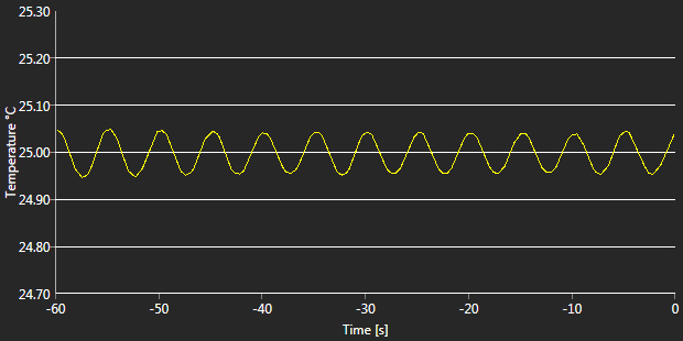
- 上記9.(図10)の図を使用して限界周期(つまり1振動サイクルの時間)を計算します。60 sの範囲内での振動回数を数え、その数で60を割ります。この例では11.8周期あるため、1周期は約5.085 sであることが分かります。
- Critical Gain(上記10.の限界ゲイン)とCritical Period Duration(11.の限界周期)をGUI(図11)に入力します。Enterを押してPIDの配分値とCycle Time(サイクル時間)の計算を開始させます。計算されたループパラメータはすぐに表示されます(図12)。
一般的にPIDの最適化設定はここで終了します。必要に応じてPID値とサイクル時間を手動で微調整し、熱負荷の変化に対するループの応答性を最適化することも可能です。
PIDパラメータの保存
TECドライバには一時的に記憶させるための揮発性メモリと、不揮発性のフラッシュメモリの両方が付いています。フラッシュメモリは消去/書き込みの回数に制限があるため、GUIに入力されたパラメータは、お客様が指定しない限り揮発性メモリに保存されます。つまりパラメータはすぐにドライバの動作に適用されますが、ユニットの電源が落ちると保存されません。すべてのパラメータを不揮発性フラッシュメモリと揮発性メモリの両方に保存するにはGUIのMTD FlashボタンのSave Settingsを押してください。次にユニットの電源を入れたときには、不揮発性メモリに保存されたパラメータが適用されます。

図12: 最終的に計算されたPIDパラメータ

図11: Critical Gain(限界ゲイン)とCritical Period Duration(限界周期)の入力
PIDパラメータはGUIを利用しているPCにも保存できます。TECドライバの操作にGUIを使用すると、次回に起動したときに保存されていたパラメータが読み込まれ、すべての入力欄が自動的に埋まります。その後、お客様がパラメータを揮発性メモリのみに保存するか(ドライバがすぐに使用するパラメータとなります)、揮発性と不揮発性メモリの両方に保存するかを選択できます。
注意
サイクル時間は内部のデジタル制御ループのタイムベースであり、限界ゲインと限界周期の入力により自動的に計算されます。このサイクル時間を手動でリセットした場合、ファームウェアはIとDの配分値を再計算します。
最適化されたPIDパラメータは、設定温度や周囲環境(周囲温度、温度制御対象物の温度)に依存する定常状態に対して有効です。動作条件や周囲環境の変化により、PIDパラメータの再調整が必要な場合があります。
PID回路の詳細は「PIDチュートリアル」タブでご覧いただけます。
PIDの基礎
PID回路は制御ループフィードバックコントローラとしてよく用いられており、さまざまなサーボ回路として広く使われています。 PIDとは、それぞれ比例(Proportional)、積分(Integral)、微分(Derivative)の頭文字で、PID回路の3つの制御設定を表しています。 サーボ回路の役割は、システムを長時間所定値(目標値)に保持することです。 PID回路は、出力を目標値に保持するため、主に目標値と出力値の差をエラー信号として発生させることにより、システムをアクティブ制御しています。 3つの制御は、時間依存型エラー信号に関連しています; 端的に言うと、次のように考えることができます。 比例は出力値のエラー、積分は過去の累積エラー、微分はエラーの予測によっています。 各制御の結果は、その後回路の電流を調整する加重和にフィードされます(u(t))。 この出力は制御デバイスへ送られ、その値は回路へとフィードバックされ、回路の出力を目標値に到達させ保持するようアクティブ安定化の処理が行われます。 以下のブロック図は、PID回路の動作を簡略化したものです。 システム要求や要件によって、サーボ回路に1つもしくは複数の制御を使用することができます(例: P、I、PI、PD、PID)。
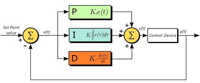
PID回路の適正な制御設定によって、最小限のオーバーシュート(目標値超過)とリンギング(目標値振動)で、素早い応答速度を実現できます。 ここで半導体レーザの温度安定化に用いられる温度サーボを例にとってみましょう。 PID回路は、最終的には熱電冷却素子(TEC)への電流を自動制御します(多くの場合FET回路上のゲート電圧の制御を通して行われます)。 この例では、電流は操作変数(MV)とします。 サーミスタは半導体レーザの温度モニタとして用いられ、サーミスタにかかる電圧を処理変数(PV)とします。 目標値(SP)の電圧は指定の温度に対応して設定します。 エラー信号e(t)は、SPとPVの差分を表します。 PIDコントローラはエラー信号を発生し、目標値に到達するようMVを変更させます。 例えばもし、e(t)の状態が半導体レーザの過熱を示せば、回路はTECを通してさらに電流を流すよう促します(比例制御) 。 比例制御はe(t)に比例するので、半導体レーザを十分な速度で冷却できないかもしれません。 その場合、累積エラーから判断し、目標値へ到達させようと出力を調整し、回路はTECを介してさらに電流量を増加させます(積分制御)。 SPに到達すると[e(t)が0に近づくと]、回路はSPに達するのを見越してTECを通して電流を減少させます(微分制御)。
PID回路は適切な制御を保証するものではないことにご注意ください。 不適切なPID制御の設定は、回路を著しく振動させたり、制御の不安定を引き起こす可能性があります。 正しい動作は、PIDの適正な調整によって得られます。
PID理論
PID制御回路u(t)の出力を得る方程式は以下となります;
Kp= 比例利得
Ki = 積分利得
Kd =微分利得
e(t)=SP-PV(t)
ここから制御ユニットは数学的定義によって定義づけることができ、個々の制御についてもう少し詳しく考察することができます。 比例制御は、エラー信号に比例します。これは、回路が発生させたエラー信号に対する直接的な応答です:
より大きな比例利得は、より大きな変化をエラーへの応答にもたらし、コントローラがシステムの変化に応答できる速度に影響を与えます。 比例利得の値が高いと回路の応答を素早く行えますが、あまりに高い場合は、SP値に対して振動を引き起こしてしまいます。 値が低すぎる場合は、回路はシステム変更への応答性が悪くなります。
積分制御は、比例利得よりさらに1段階ステップが進み、エラー信号の大きさだけでなく、エラーの期間にも比例しています。
積分制御は、比例制御のみによる定常誤差を除去するとともに、回路の応答速度向上に非常に高い効果をもたらします。 積分制御は、未修正の過去のエラーを合計し、エラーにKiを乗算することで、積分応答を出します。 従ってわずかな継続エラーに対しても、大規模な集積積分応答を実現することが可能です。 しかしながら、積分制御の高速応答に起因して、高い利得値による目標値の著しい超過が生じ、振動と不安定性を引き起こします。 低すぎる場合、回路のシステム変更への応答速度が著しく低下します。
微分制御は、比例制御および積分制御から予測される目標値超過とリンギングを低減させます。 回路が時間の経過とともにどう変化しているか(エラー信号の微分から判断)素早く決定し、Kdを乗算することで微分応答を出します。
比例や積分制御と異なり、微分制御は回路の応答を減速させます。 そのため、積分制御や比例制御によって引き起こされた振動を抑制したり、超過を部分的に補うことができます。 高い利得値は回路の応答性にかなりの減速を生じさせ、ノイズや高周波振動が発生しやすくなります(回路が迅速に応答するには低速すぎるため)。 低すぎると、回路はSP値を超過する傾向にあります。しかしながら、SP値を著しく超過するケースは避けなければならず、そのためより高い微分利得(より低い比例利得とともに)が用いられます。 下記の図は、個々のパラメータの利得の増加による影響を示しています。
| Parameter Increased | Rise Time | Overshoot | Settling Time | Steady-State Error | Stability |
|---|---|---|---|---|---|
| Kp | Decrease | Increase | Small Change | Decrease | Degrade |
| Ki | Decrease | Increase | Increase | Decrease Significantly | Degrade |
| Kd | Minor Decrease | Minor Decrease | Minor Decrease | No Effect | Improve (for small Kd) |
チューニング
通常、適切なサーボ制御を得るために、P、I、Dの利得値は個々で調整する必要があります。 どのシステムに対してもどの値にするべき、といった決まった一連のルールがあるわけではありませんが、基本手順に沿ったチューニングは各々のシステムや環境に合わせるのに役立ちます。 概して、PID回路はSP値の超過をわずかに起こし、その後SP値に到達させるため素早く減衰するようにします。
手動による利得設定のチューニングは、PID制御設定において最もシンプルな方法です。 しかしながらこの手順はアクティブで行われ(PIDコントローラがオンとなり、システムに正しく接続されている)、完全に設定するには多少の経験を要します。 PIDコントローラを手動で調整するには、まず始めに積分および微分利得を0に設定します。 出力に振動が現れるまで、比例利得を上げてください。 比例利得はこの値の約半分の値に設定します。 比例ゲイン利得設定後は、任意のオフセットがシステムに合わせた適切なタイムスケールに修正されるまで積分利得を上げてください。 上げすぎた場合は、SP値の著しい超過と回路の不安定性が引き起こされます。 積分利得が設定されたら、次に微分利得を上げてください。 微分利得はオーバーシュートを軽減し、システムを迅速にSP値へ収束させます。 微分利得を上げすぎると、大幅な超過が生じます(回路の応答が低速すぎるため)。利得設定を試行することにより、システムが変化へ素早く応答し、SP値の振動を効率よく減衰させるといった、PID回路の性能を最大限にすることができます。
| Control Type | Kp | Ki | Kd |
|---|---|---|---|
| P | 0.50 Ku | - | - |
| PI | 0.45 Ku | 1.2 Kp/Pu | - |
| PID | 0.60 Ku | 2 Kp/Pu | KpPu/8 |
手動によるチューニングは非常に効果的なPID回路の設定方法ですが、ある程度の経験とPID回路および応答についての理解を必要とします。 PIDチューニングのためのZiegler-Nicholsメソッドは、もう少し体系的な手引きとなっています。 再び、積分利得と微分利得をゼロ値にセットしてください。 比例利得を回路が振動するまで上げます。 この利得をレベルKuと呼びます。 振動はPuの期間です。 個々の制御回路の各利得は右の表に示しています。
| Posted Comments: | |
Peter Doherty
(posted 2024-02-18 12:29:56.707) If that TEC controller worked to control cooled sensors down to -20 C, I think that would make it even more useful.
Anyway to make it do that?
Thank you. hkarpenko
(posted 2024-02-20 11:24:39.0) Dear customer,
thank you very much for your feedback. I will forward your suggestion to our development team. Dietmar Fischer
(posted 2023-10-24 14:24:56.137) We have received a new batch of your MTD415T controllers. Surprisingly, they show a difference behavior than the controllers that we had ordered in 2021.
PID control for specific Coherent OPSL modules works fine with the controllers from 2021 but cannot leads to heavily oscillating temperatures for the 2023 batch. We used the same set of PID parameters for both modules and did tests for several OPSL modules and several MTD controllers.
What is the difference between 2021 and 2023 versions of your controllers? Daniel Mitrani
(posted 2023-08-31 11:26:25.697) I have an MTD415L module mounted in the MTD Evaluation Board. When testing it with the MTD Series software, I notice a couple of issues:
1) The current limit function does not work.
2) The polarity of the Peltier connection pins on the module is not in correspondence with the convention used by Peltier manufacturers. I.e., a current flowing from TEC+ (red cable) to TEC- (black cable) should cool the bottom side of the Peltier when observed with the red cable on the left side.
Could you please comment.
Best. jweimar
(posted 2023-09-04 09:25:59.0) Thank you very much for your feedback. Unfortunately, among TEC elements the naming of the TEC+ and TEC- is not consistent. This means that it is possible the MTD diver will cause the TEC element to heat instead of cooling when connected. I will contact you directly to provide further assistance. Frederik Schröder
(posted 2023-06-28 14:42:42.353) Hi, as already requested, I am wondering about the temperature range. Would it be possible to increase the temperature range of the MTD415T and the MTDEVAL1, ideally to -50 until 100 C? Thank you in advance! dpossin
(posted 2023-07-05 05:42:52.0) Dear Frederik,
Thank you for your feedback. Unfortunately we can´t offer an extended temperature range, since the built in thermistor doesn´t show a linear behaviour at those temperatures any more. The second reason why we can´t extend is that the ADC is not able to resolve a greater temperature range. I contact you directly to discuss this further. Berat Can Çekiç
(posted 2023-05-05 19:56:24.327) Hello,
We are using MTD1020T and getting unwanted data types such as -
- şşşşşşşşşşşşşşşşşşşşşşşşşşşşşşşşşşşşşşşşşşşşşşşşşşşşşşşşşşşşşşşşşşşşşşşşşşşşşşşşşşşşşşşşşşşşşşşşşşşşşşşşşşşşşşşşşşşşşşşşşøÈÂÀàøø€øäøòü€ü‚{FF}şüş{FF}à€äø€ÀÀ€²üàúÀ·üğžçüêûşüïşş{FF}€{FF}{FF}àòğàùÌøûğş‚Èüışşşşøş`ÂüşáüøüüòàøşşàşèğÄøüşøşüø€şÀğøüû€şøøÀüøÀøäşøüüşüıˆøşÀşüüüüÀüüıüøàøàøş{FF}ÀàÑúşøşòùø€ğşàÀàş‚€ğøàààøüÀøàşüüûğşğüà{FF}Øüøøü€üùşøüøğûüøòøøü{FF}{FF}úóøğàààùĞİøÅü€Àà -
The baud rate , data bits , stop and priority bits configurations have been done as its datasheet but still not getting proper commands . Im using USB-TTL convertor in order to Tx and Rx . How can we solve that problem ? GBoedecker
(posted 2023-05-08 10:07:53.0) Thank you very much for your feedback! Using the MTDEVAL1 evaluation board facilitates handling of the MTD1020T, since you can directly connect a standard USB cable. I will contact you directly about how to connect the MTD1020T with an adapter. Leonard Höck
(posted 2023-02-10 14:06:59.547) I just did a reset of the error register and now get the error code 17 when I check the register. Before the reset it was 0.
What does the error code 17 mean? I couldn't find anything in the data sheet. Thanks in advance wskopalik
(posted 2023-02-13 10:48:32.0) Thank you very much for your feedback!
The error register of the MTD415T chips has 16 bit and each bit indicates a different error event. If more than one error event occurs at the same time, the bits for each error event will be added, e.g. 17 corresponds to 1 + 16.
If you get the error code as a decimal number, it is usually best to convert it to a binary number. For 17 this would be 0000 0000 0001 0001. Then you can compare it to the error register in the data sheet. In this case, the bit numbers 0 and 4 are active (starting with 0 on the right) and set to 1 so these two errors are currently present on the system.
I will contact you directly to provide further assistance. user
(posted 2022-11-17 20:53:29.483) 15 TEC - TEC Element negative connection
Connect this pin to the positive terminal of the TEC element. 1
)
16 TEC + TEC Element positive connection
Connect this pin to the negative terminal of the TEC element. 1
) wskopalik
(posted 2022-11-18 03:31:41.0) Thank you very much for your feedback!
Unfortunately, the naming convention of the TEC+ and TEC- connections is not consistent among TEC elements. Therefore, it is in some cases necessary to reverse the polarity of the TEC connections to work properly with the MTD drivers.
I will contact you directly to provide further assistance. user
(posted 2022-11-16 10:05:25.49) I have a MTD415T, I have to reverse the TEC connections to make it to work.: pin-16 of MTD415T to pin-14 of SLD1005S (butterfly laser package);pin-15 to pin-1. what can be wrong? wskopalik
(posted 2022-11-18 03:13:30.0) Thank you very much for your feedback!
Unfortunately, the naming convention of the TEC+ and TEC- connections is not consistent among TEC elements. Therefore, it is in some cases necessary to reverse the polarity of the TEC connections to work properly with the MTD drivers.
I will contact you directly to provide further assistance. user
(posted 2022-06-28 01:42:20.713) Like others, I am very eager to extend the temperature limits of the MTD and MTD eval (e.g to -10 or colder). Is it possible to remove or edit the limit temperatures? hkarpenko
(posted 2022-07-01 06:10:21.0) Dear Alexander,
thank you for your interest in our products.
I am reaching out to you to discuss this further. Daniel Sablowski
(posted 2022-02-01 11:21:00.733) Dear Thorlabs-Team, is it possible to use TEC controller with higher currents (with heat sink) with your evaluation board? 10A would be my requirement. Thanks and best regards, Daniel soswald
(posted 2022-02-09 03:11:13.0) Dear Daniel,
thank you for your feedback. I have reached out to you directly to discuss your application in more detail and see if we can offer a suitable solution. C. Peppermueller
(posted 2021-12-06 11:32:45.99) We would like the MTD415L even more if it would allow a larger temperature range. Is there a way to extend the limit temperatures (5C, 45C)? We would love e.g. -5 to 70 C, or even hotter at the upper end. Is there a way to do that?
Thank you in advance,
Christian (Peppermueller) dpossin
(posted 2021-12-08 03:14:33.0) Dear customer,
Thank you for your feedback. I am reaching out to you in order to discuss this with you. Michael Levin
(posted 2021-06-07 23:53:12.06) Hi Thorlabs team,
I would like to make a remark regarding the output polarity of the MTD415T controller. A while ago, someone already asked this question (he had to revert the polarity while working with a butterfly laser). Your engineer replied that the actual polarity depends on how the TEC is mounted in the system. In general, this is correct.
But, practically, when you are working with a closed package (typically a laser or a detector, as in my case), the package pinout is so defined that positive voltage difference across its TEC results in cooling rather than heating of the active element. Therefore, in many applications (not to say in most), the TEC polarity is well-defined, and it would be nice if the output polarity of MTD415T were defined in just the same way, namely:
"The positive voltage difference between the TEC+ and TEC- terminals of the controller must result in cooling the active element to which the TEC is attached within the same package". I believe this is the natural way to define the output polarity of the controller, but unfortunately the actual polarity is reversed.
Another suggestion is to provide in the datasheet the value of the controller's efficiency, as this will help to choose the correct power supply for the controller. Now the datasheet only mentions "high efficiency", which is a not well-defined term.
Now I must say that the controller itself works very good, and my suggestions are only about the documentation.
Best regards,
Michael MKiess
(posted 2021-06-10 10:50:18.0) Dear Michael, Thank you very much for this feedback. Such suggestions for improvement can help us to better document our products, make them understandable and continuously improve them. We will address these points. Thank you for this helpful feedback. Christian Zingl
(posted 2021-05-25 05:34:15.747) There seems to be a problem using the MTD1020T on-board PID tuning algorithm. The sequence of sending the G and O commands determines whether or not the MTD1020T applies the PID coefficients.
I initially start with a MTD1020T with the PID and C parameters set to values not fitting my TEC system. Then I try to adjust the PID using the G and O commands.
There are two choices of sequencing when setting G and O:
- Apply power, then first send the G command, then the O command. Doing so results in oscillation or other unpredictable behavior as expected with wrong PID values
- Apply power, then first send the O command, then the G command. Now the PID controller works as expected.
Reading the P, I, D and C values returns the exact same values in both cases. It just seems that in one case, the values are not sent to the actual controller. This happens consistently over multiple retries with power cycles in between. MKiess
(posted 2021-05-28 06:42:58.0) Dear Christian, Thank you for your inquiry. I have contacted you directly to discuss the details and provide further support. Christian Zingl
(posted 2021-04-20 08:29:49.903) Dear Thorlabs Team,
it would be nice for the MTD1020T to support adjustable NTC coefficient with permanent storage (like for the PID settings).
Kind regards MKiess
(posted 2021-04-21 08:52:16.0) Dear Christian, Thank you for this feedback. Such feedback helps us to develop and improve our products. For these TEC drivers we also have the possibility to produce special designs with desired parameters for higher quantities.
A possible alternative would be our TED4015. Here you can e.g. set the NTC values as desired. Artem Gulyaev
(posted 2020-12-23 12:02:02.997) Hi,
Just for a bit convenience for the end user, could you please add in your datasheet that MTD415L answers for every "set" command with either
* corresponding value which was set
* with error message
surprisingly is was never declared in the datasheet, while is true.
Also probably error resetting mask also would be of some use - usually users might want to reset minor errors (like invalid value set attempt) while keeping the important ones. So "c" command might be accompanied with a mask value to erase.
Kind Regads,
Artem Gulyaev MKiess
(posted 2021-01-21 08:41:25.0) Thank you very much for this feedback. We will take a closer look at this topic again and see how we can make this more accessible to the end user, as described by you. Thank you very much for this suggestion. Such comments help us to constantly improve our products. Ludovic Angot
(posted 2020-07-23 07:43:40.233) I am currently writing my own code to use the MTDEVAL1 on a single board computer, the first step being a loopback test. To do so, can I safely only connect the USB cable and put a jumper on pins 12 and 13 (corresponding e.g. to TX and RX on the MTD1020) of either one of the carrier socket of the MTDEVAL1? Or does the evaluation board need to be powered via the Screw terminal 1 in order for the USB to UART to function? dpossin
(posted 2020-07-24 08:09:19.0) Dear Ludovic,
Yes, with no MTD module inserted you can use a jumper between pins 12 and 13 for the loopback test.
You don’t need to add an external power supply. user
(posted 2020-07-01 18:13:53.153) How many number of times can we program to the flash memory on MTD415T? Thank you. MKiess
(posted 2020-07-06 07:56:37.0) This is a response from Michael at Thorlabs. Thank you very much for your feedback. Depending on the application, more than 100k erase / write cycles are possible for the non-volatile memory (flash). We have the possibility to adapt the settings for your specific application to maximize the lifetime of the controller. I have contacted you directly to discuss this with you in more detail. user
(posted 2020-04-20 18:09:33.047) This is a nice product, I think two changes/variations would make it great.
1) A higher temperature version.
Many devices, such as doubling crystals, need to run at higher temps. I imagine you don't allow higher than +45 C because you cannot guarentee the ~ mK accuracy. For many applications ~ mK is not required. (For those out there who need a higher temp add a resistor to one of the sensor wires. The temp reading will no longer be accurate, and thorlabs specs won't hold at the higher real temp, but it works fine.)
2) compact version.
Although this is an eval board it would be quite useful if the footprint was reduced. It seems like it could be cut in half easily, maybe even by more with some effort. wskopalik
(posted 2020-04-21 11:57:11.0) This is a response from Wolfgang at Thorlabs. Thank you very much for your feedback!
We appreciate any feedback that helps us to improve our products. I will forward your suggestions to our engineering team so we can consider them for future releases in this product line. user
(posted 2019-10-23 08:32:31.37) The screw terminals for TEC+ and TEC- are too large to make proper contact with AWG 22 / 0.3 mm2 wires. The wire will be held in place barely, but will not have proper contact and can be pulled out by a little bit of force. Be sure to use suitable wires with larger cross sectional area to ensure proper contact.
The screw terminals for the power supply and sensor connection are both OK and don't have this issue. MKiess
(posted 2019-10-29 11:49:46.0) This is a response from Michael at Thorlabs. Thank you very much for your feedback. We appreciate any feedback that helps us to improve our products and helps all users to use them. user
(posted 2019-09-10 11:47:03.03) I'm controlling the PTC1 with my own SW via serial port according to the programmers reference of the MTD1020T, but I have encountered some communication problem.
The documentation is wrong, the Command/Response terminator is CR and not LF and each response value is followed by char '>' (62/0x3E). MKiess
(posted 2019-09-20 03:58:05.0) This is a response from Michael at Thorlabs. Thank you for the feedback. We will take a look at this and correct the documentation. Thank you very much for this information. Ludovic Angot
(posted 2019-07-29 22:40:27.34) I am planning to use the MTDEVAL1 on a linux system. I have already taken note of the programmer's reference of the TEC modules but there's nothing about UART control in the MTDEVAL1 manual. Could you please provide any guidelines to get me (and probably others) started on this? It may be as simple as connecting the eval. board, detecting the USB port and then send the appropriate commands, but I prefer to know beforehand to avoid any mistake. A short section on the topic could be added to the user manual. Also in paragraph 3 Operating Principle of the MTDEVAL1 manual, reference is made to saving the parameters to an XML file, could you provide an example of such an file? dpossin
(posted 2019-08-28 04:45:02.0) Dear Hinoki,
Thank you for your Feedback. The MTD Series uses standard serial communication over a virtual COM port for data transfer.
To control one of our MTD modules with a Linux based system you just need to use the operating system proprietary serial communication interface and you can use the standard commands mentioned in the manual.
I hope that helps. user
(posted 2019-07-09 17:16:26.473) Hi, is there a way to change the y-axis range in the MTD software? If my set temperature is 25 C, can I set the temperature range in the y-axis to 25+- 0.1C or something else? dpossin
(posted 2019-07-17 08:25:15.0) Dear customer,
Thank you for your feedback. You can adjust the viewing range of the temperature graph by setting the range on the left hand side by setting the desired range in the field "Temperature Window". Ingo Gersonde
(posted 2019-03-26 05:01:19.65) I use the MTD415TE on an evaluation board, applied to TEC and thermistor of a laser head. When i use the D_Share value, i get severe noise on the TEC current. Can one filter the temperatur signal or the TEC-output signal ?
Thank you in advance
Ingo Gersonde swick
(posted 2019-03-26 09:19:15.0) This is a response from Sebastian at Thorlabs. Thank you for the feedback.
The noise on TEC current could be caused by unshielded cables for the signal from Thermistor or D-Share value is set too high. In first case noise in sub-mV regime triggers D-share and in second case the value of D-share is too high in respect to P and I share. For improved noise immunity signals should be guided in shielded and twisted cables with reduced length. If PID values are not optimal please follow our guideline on the website at tab "PID Oscillation Test" or in the manual chapter 7.
I contacted you directly for further troubleshooting. Matthias.Nagel
(posted 2018-08-06 15:53:41.887) Can I drive 2 x ET-031-10-20 with the MTD1020T and th evaluation board? nreusch
(posted 2018-08-08 08:37:51.0) This is a response from Nicola at Thorlabs. Thank you for your inquiry. I checked the voltage and current requirements of the Peltier element you mentioned: Maximum current is 2.5 A and maximum voltage 3.8 V. Therefore, you should be able to drive two elements in a series connection since the voltage drop across two elements is 7.8 V, i.e. lower than the specified 10 V for MTD1020T. Please note that the maximum output current of MTD1020T is 2.0 A, so it will not allow you to drive the elements at their maximum current. The recommended TEC elements for this driver are TECH3S, TECL4 and TECJ6. I will contact you directly to discuss further details of your specific application. ward.becelaere
(posted 2018-04-11 15:43:46.01) According to the specs, the temperature range is between 5 and 45 C.
For my application I need a range between 15 and 75 C. Is there any way to have an extended range? Maybe a different thermistor?
Thanks! swick
(posted 2018-04-17 03:56:10.0) This is a response from Sebastian at Thorlabs. Thank you for the inquiry. For OEM applications we offer customizations suitable to a wide range of requirements. Customization of the MTD1020T for an other temperature range is possible. We contacted you directly for further discussion. xjiang225
(posted 2017-12-01 23:46:02.757) I have installed the MTD software but could not find the device in the software("Scan USB" doesn't give any result). I can see the device as both COM port and USB port in device manager. The "POWER SUPPLY" LED3 is the only LED that is on on the board. Could you please suggest some possible issues that are causing this? Thanks! swick
(posted 2017-12-05 04:33:13.0) This is a response from Sebastian at Thorlabs. Thank you for the inquiry. I have contacted you directly for troubleshooting. user
(posted 2017-11-15 09:58:43.903) Can you share more information about the thermistor readout circuit; as well as the expected thermistor B constant?
I need to design an interface circuit so that I can use a different type thermistor (R=9kOhm, B=~3400K) mvonsivers
(posted 2017-11-21 03:29:16.0) This is a response from Moritz at Thorlabs. Thank you for your inquiry. Unfortunately, MTD415T can only be used with 10 kOhm thermistors. However, the MTD-Modules can be customized for high quantity orders. Please contact techsupport@thorlabs.com for further information. mvonsivers
(posted 2017-11-22 03:59:56.0) This is a response from Moritz at Thorlabs. Our engineers have found a workaround for your problem. You can connect your 9 kOhm thermistor directly to the MTD415T module. In this case, you will get an offset between real temperature and read out value. This offset has to be taken into account when setting the set temperature.
Our MTD modules are calibrated for a B constant [25/85°C] = 3950 K. Your slightly different B constant will lead to a non-linearity over the complete temperature range. If your application requires only temperature stabilization at one operating point you should still be able to find the right PID parameters.
As already mentioned, for an OEM application we can modify and calibrate the MTD module according to your specifications. rogier
(posted 2017-09-29 17:38:09.133) Hello,
It seems that your current manual is not up-to-date. The programmers reference is saying that you should use quotations marks around the commands it seems with the new firmware update (1.0.5) on the MTD1020T this is no longer needed. The response isn’t written in brackets either as suggest in the manual. swick
(posted 2017-10-05 03:33:56.0) This is a response from Sebastian at Thorlabs. Thank you for the inquiry.
In the manual at chapter 5.1 you can find the nomenclature used for this device. The quotation marks or brackets are not part of the command or received message. This nomenclature makes it easier to distinguish between commands, received messages and formats.
I will contact you directly for further assistance. chkwak
(posted 2017-08-11 15:07:47.68) Hello
I buyed MTD415TE,
but this error message occur frequently,
"TEC current was too long time on the limit without influence on the temperature."
Let me know how to fix it. mdiekmann
(posted 2017-08-16 10:58:42.0) This is a response from Meike at Thorlabs: Thank you for contacting us! This error typically indicates that the thermal load is too large for the module to handle. It is a safety feature to prevent the unit from overheating. We will contact you directly to troubleshoot the issue in your case. slawomir.drobczynski
(posted 2017-07-17 00:38:43.053) I am using MTD415T and I would like to increase temperature from 25 to 36 degrees of Celsius. I start with factory default settings, why after few seconds TEC current is zero and Error Register: Thermal Latch-Up (TEC current at limit without temperature improvement) ? wskopalik
(posted 2017-07-20 06:01:23.0) This is a response from Wolfgang at Thorlabs. Thank you very much for your feedback.
Our MTD modules have a wide variety of safety features which can be en- or disabled by the costumer if needed.
The ”Thermal-Latch-Up Error” prevents the cooling system from over-heating. The module measures the output power of the module and if no change in terms of TEC temperature is recognizable, the module switches the output off to prevent the system from over-heating.
This can e.g. happen for very large thermal loads, because the change in temperature will happen very slow in this case. Please consider that the MTD415T is not designed to drive very large thermal loads. In normal operation this safety feature should not be triggered.
As a workaround for your application, you could disable the corresponding safety bitmask. You need to send the command "S251" over a terminal program to the module for this.
I will contact you directly to provide further assistance. krevety
(posted 2017-06-14 09:31:07.563) Are you planning a replacement for MTDEVAL?
btw. Excellent product, I like the MTD control app. tcampbell
(posted 2017-06-16 10:42:16.0) Response from Tim at Thorlabs: Thank you for your feedback. Yes, we have been developing a replacement for the MTDEVAL and it should be available for purchase shortly. j.zeludevicius
(posted 2017-01-06 05:28:39.763) I would like to express my two issues with MTDEVAL board and MTD415TE controller.
I used this controller for temperature stabilization of pump laser diode in 14-pin butterfly package. Controller board was connected to NTC 10K thermistor and TEC. When I connected TEC leads correctly (+ to +, and - to -) I got erroneous behavior of the controller. It decreased temperature (up to minimum value) when the temperature had to be increased. I reversed TEC connection polarity and then It worked correctly. Could you check whether there is any error in controller design?
Second issue is with operation status LED. When USB cable is disconnected the status LED turns off and it is not clear whether temperature control is active or is switch off as well. Could you comment on that? I have observed that status LED lights up whenever USB cable is connected to any source providing +5V, not necessary a computer. swick
(posted 2017-01-09 04:16:46.0) This is a response from Sebastian at Thorlabs. Thank you very much for the feedback.
Your description is exactly how the MTD modules are designed to work, your MTD module and the Evaluation board are working fine.
Let me explain this in more detail:
TEC:
The described behavior, that you need to change the polarity of the TEC element is based on the mounting direction of your TEC element. You can change hot and cold site by changing the polarity of the lead wires or by changing the mounting direction of the TEC element itself. Please be aware, that Thorlabs cannot predict the mounting direction of each TEC element, so by changing the polarity of the lead wires you have the maximum flexibility.
For your information: By using the MTD Software you will get an error code, which describes if the TEC element is connected in the wrong way.
LED:
Please refer to the manual for the function of the LED. The LED describes not if the MTD module is en- or disabled. It signals if the temperature is within the programmed temperature window. This is a very helpful feature to interface other (analog) circuitry to get a “Temperature Ready Signal”.
To use this function correctly we recommend to adjust the “Temperature Window” and the “Temperature Protection Delay” in the right way.
I will contact you directly for further assistance. gtoner2506
(posted 2016-12-21 05:05:49.833) I need to talk to this device using an embedded processor. Is ther a serial command set for it? wskopalik
(posted 2016-12-22 08:09:50.0) This is a response from Wolfgang at Thorlabs. Thank you for your inquiry.
These termperature controllers have an UART programming interface. A list of commands can be found in the manual from p.12 on.
I will contact you directly to discuss your application in more detail. cbrideau
(posted 2016-12-06 14:37:03.893) That was quick! The eval board looks great: Next challenge is to put connectors on this eval board and the LD eval board so you can put them together in a stack and share power supplies. swick
(posted 2016-12-07 03:17:26.0) This is a response from Sebastian at Thorlabs. Thank you for the feedback. We will discuss your suggestion in our internal forum. cbrideau
(posted 2016-11-30 15:51:30.177) Would be nice to see a daughter board and evaluation board for these like the MLD203 series laser drivers. An evaluation board that sockets one of the MLD203's AND one of these temperature controllers would be very handy for proto builders and evaluating the performance of the controllers. tfrisch
(posted 2016-12-02 02:42:40.0) Hello, thank you for contacting Thorlabs. I have posted this in our internal engineering forum. |

 ズーム
ズーム
Click to Enlarge
ドーターボードに取り付けたTECドライバMTD415TE
- MTD415シリーズ:SMTパッケージならびにドーターボード取付けタイプ
- MTD1020T:THTパッケージ
- ドーターボードならびにTHTパッケージは評価ボードMTDEVAL1(下記参照)に直接取り付けが可能
- 対応する温度センサ
- 10 kΩサーミスタ
- IC温度センサLMT84
- コマンドラインまたはGUI制御(「ソフトウェア」タブ参照)
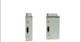
MTD415シリーズ
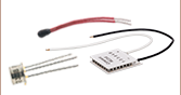
MTD415シリーズは16ピン表面実装(SMT)型パッケージ、またはこのパッケージをドーターボードに取り付けたタイプでご用意しております。MTD415シリーズは放熱が小さいため、ヒートシンクなどの外部放熱機器の必要性も最小限に抑えられています。21.0 mm × 12.4 mm × 3.1 mmとコンパクトなSMTパッケージは、メッキ加工されたハーフホールにより接続できるため、表面実装や電気的接続が簡単です。ドーターボードはSMTパッケージのアダプターボードとして機能し、評価ボードMTDEVAL1(下記参照)に直接取り付け可能です。
こちらのTECコントローラの最大出力は6 W、最大TEC電流は±1.5 Aです。MTD415L(E)はIC温度センサLMT84、MTD415T(E)は10 kΩサーミスタに対応します。TEC出力やTEC電流と負荷抵抗の関係を示すグラフについては「仕様」タブをご覧ください。ピン配列図と典型的な応用回路図は「ピン配列」タブでご覧いただけます。
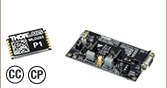
MTD1020T
MTD1020Tはヒートシンク内蔵のスルーホール実装(THT)型パッケージでのご提供です。このパッケージにより、PCBに組み込みが可能で、かつ評価ボードMTDEVAL1のソケットに直接接続が可能です。 最適動作を得るためには、周囲温度が20 °Cを超える場合、MTD1020Tをアクティブに冷却することをお勧めいたします。
TECコントローラMTD1020Tの最大出力は20 Wです。推奨動作条件において適切に冷却されている場合、5 Ωまでのあらゆる負荷抵抗に供給可能な最大TEC電流は±2.0 Aです。負荷抵抗や冷却状態に対する出力の依存性を示したグラフや、冷却状態で供給可能な電流のグラフについては「仕様」タブをご覧ください。MTD1020Tは10 kΩサーミスタに対応します。MTD1020Tを使用してピン配列図と典型的な応用回路図は「ピン配列」タブでご覧ください。
大量発注時のディスカウントについて
こちらのTECドライバは、大量発注によるディスカウントが可能です。最新の価格表は、下の「Volume Pricing」のリンクをクリックしてご覧いただけます。 MTD415シリーズドライバの大量注文については、ICチューブでのお届けも承ります。
| Item #a | Supported Temperature Sensor | TEC Compliance Voltage | Output Current (Max) | 16 Pin Package Type | Mounts on Evaluation Board | Recommended TEC |
|---|---|---|---|---|---|---|
| MTD415L | LMT84 IC | 4.0 V | ±1.5 A | SMTb | No | TECF2S, TECH4 |
| MTD415LE | LMT84 IC | 4.0 V | ±1.5 A | Daughterboard | Yes | |
| MTD415T | 10 kΩ Thermistor | 4.0 V | ±1.5 A | SMTb | No | |
| MTD415TE | 10 kΩ Thermistor | 4.0 V | ±1.5 A | Daughterboard | Yes | |
| MTD1020T | 10 kΩ Thermistor | 10.0 V | ±2.0 A | THTc | Yes |

 ズーム
ズーム

Click to Enlarge
ドライバMTD415LEを搭載した評価ボード
- 外側のソケットでドーターボードMTD415LEならびにMTD415TEを取り付け
- 内側のソケットでTHTパッケージのMTD1020Tを取り付け
- ネジ端子:
- 12 VDC、2.3 A電源用
- TEC接続用
- 温度センサ接続用
- GUI制御用USBコネクタ(「ソフトウェア」タブ参照)
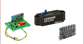
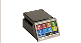
評価ボード
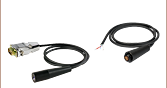
評価ボードMTDEVAL1は、組み込み用TECドライバ(上記参照)がすぐ研究室やテスト環境で使用できるようになるブレイクアウトボードです。MTDEVAL1は12 V電源、TEC、温度センサに接続し、TECドライバを簡単にPC制御可能にします。取り付けたドライバをPC制御可能にするためには、まずUSB-AB-72(下記参照)などの対応ケーブルを使用してPCとMTDEVAL1の2.0 USB type Mini Bポートに接続します。評価ボードをPCに接続すると、UART経由でテキストコマンド(データシートに記載)を送るか、あるいは「ソフトウェア」タブからダウンロードできるMTD GUIを使用することで、基板に取り付けたTECドライバの設定を変更することができます。GUIを用いると、制御ループのパラメータを手動設定できるだけでなく、振動試験の結果を用いて最適なP、I、Dのパラメータを計算することができます(詳細は「PID振動試験」タブをご覧ください)。MTDEVAL1をPCに接続する前に、ドライバーソフトウェアをインストールしてください。接続後にインストールするとインストールエラーの原因になる場合があります。
TECドライバを自律駆動させる場合は、評価ボードをPCに接続する必要はありません。電源を基板に供給する際、TECおよび温度センサのワイヤを適切なネジ端子に接続し、SW1(ENABLE ON/OFF)スイッチをオンの位置にセットすると、TECドライバはフラッシュメモリに保存された設定に従って動作します。
対応するTECドライバ
TECドライバMTD1020Tには、基板MTDEVAL1の内側ソケットを使用してドライバを取り付け可能にするピンが付いています。MTD415シリーズのTECドライバにはドーターボード構成の製品も含まれています。MTD415LEとMTD415TEは、表面実装(SMT)型のパッケージがアダプターボードに取り付けられた製品で、アダプターボードは評価ボードの外側ソケットに対応します。
TECドライバが電気的な損傷を受けるのを防ぐため、TECドライバを取り付ける際は評価ボードMTDEVAL1から電源が取り外されていることをご確認ください。SW1(ENABLE ON/OFF)スイッチをオフの位置にするだけでは、ソケットからの電源を切ったことにはなりませんのでご注意ください。SW1は接続中のTECドライバの制御を有効または無効にする際に使用します。また、基板に電力を供給する前にSW1スイッチをオフの位置にしてください。
※MTDEVAL1の基板シルクの「TEC Connection (+)」側には、加熱が必要な場合に正電圧が印可されます。弊社TEC素子でCold Sideに温度センサを取り付けた場合には、TEC素子のマイナス端子がMTDEVAL1の「TEC Connection (+)」側になります。