 Products Home / レーザー光源および関連製品 / ファイバー出力レーザー光源 / Pre-Configured 4-Channel Fiber-Coupled 1310 nm Laser Source
Pre-Configured 4-Channel Fiber-Coupled 1310 nm Laser Source

- Four 1310 nm DFB Laser Output Channels with FC/PC Connectors
- TEC and Controller for Each Channel
- Stable, Low Noise Output
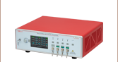
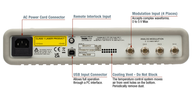
View of Back Panel
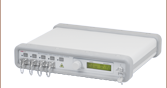
MCSL1C1
4-Channel Laser Source, 1310 nm

Please Wait
| Table 1.1 Key Specifications | |
|---|---|
| Item # | MCLS1C1 |
| Typical Wavelength | 1310 nm |
| Display Power Accuracy | ±10% |
| Current Set Point Resolution | 0.01 mA |
| Temperature Adjust Range | 20.00 to 30.00 °C |
| Temperature Set Point Resolution | ±0.01 °C |
| Noise | <0.5% Typical |
| Rise/Fall Time | <5 µs |
| Modulation Bandwidth | 80 kHz Full Depth of Modulation |
Features
- Independent Temperature Control Gives High Temperature Stability
- Four 1310 nm DFB Laser Output Channels with FC/PC Connectors
- Low Noise Output
- USB Interface
- Low-Profile Package, 2.5" (64 mm) Tall
Thorlabs' Pre-Configured, 4-Channel, Fiber-Coupled Laser Source provides easy coupling and simple control of laser-diode-driven fiber optics. Each system is equipped with four 1310 nm, distributed feedback (DFB) lasers with FC/PC fiber connectors; to discuss custom output connections, contact Tech Sales. These single-frequency laser diodes achieve a 0.1 nm typical linewidth with an excellent side mode suppression ratio (40 dB typical), and provide mode-hop-free, continuous current tuning over the full temperature adjustment range of 20.00 °C to 30.00 °C. The laser source allows more than one channel to be turned on simultaneously; however, it is only possible to adjust the power output of one at a time from the front panel.
Each laser diode is operated from an independent, high-precision, low-noise, constant-current source and temperature control unit. An intuitive LCD interface allows the user to view and set the laser current and temperature independently for each laser. The display indicates the channel number selected, the output wavelength of the source, the operating power calculated from the monitor photodiode, and the actual temperature to which the laser is set.
This device incorporates a microcontroller to fully control the laser's optical power and temperature as well as to monitor the system for fault conditions. The laser source includes a USB connection that allows remote enabling, power adjustment, and temperature adjustment. On the rear panel, analog inputs are available to modulate the laser diodes' outputs with an externally generated waveform. To prevent damage, the microcontroller will disable the output if the sum of the analog input and internal set point exceeds the laser limits.
Thorlabs offers the MCLS1-CUSTOM as a customizable, 4-channel laser source, with 31 different laser diode options. We also offer the MCLS2-CUSTOM 4-channel, fiber-coupled, customizable source with alternative laser diode and superluminescent diode (SLD) options. The MCLS2-CUSTOM source features a touchscreen interface and a modulation bandwidth of 200 kHz.
Thorlabs also offers other components suitable for the O-band, including our Praseodymium-Doped Fiber Amplifiers (PDFAs) and Booster Optical Amplifiers. Our fiber-coupled LiNbO3 modulators include FC/PC connectors for easy integration with the MCLS1C1 laser source. For all-in one solutions in high-speed fiber optic test and measurement, we offer reference transmitters, optical transmitter with phase modulators, and calibrated electrical-to-optical converters.
Safety
While the output source for the MCLS1C1 falls within the class 1 laser rating, the system was fully designed to meet laser class 3B requirements. There is an interlock located on the rear panel that must be shorted in order for any laser output to be enabled. This can easily be configured to be triggered by doors to disable the lasers in unsafe conditions. The power switch is a keylock system to prevent accidental or unwanted use. Each source has its own enable button allowing the user to choose the light source or sources he wishes to be active, as well as a master enable that must also be set. Each channel includes a green LED indicator to easily determine its current state. There is a 3 second delay before the lasers turn on, and the user is warned by the LED rapidly blinking. The laser must be turned off before connecting or disconnecting a fiber to the output ports.
In the Box
The MCLS1C1 includes a universal power supply allowing operation over 100 - 240 VAC without the need for selecting the line voltage. The fuse access is conveniently located on the rear panel. This unit is supplied with a region-specific U.S. or standard European line cord, the pre-configured laser source with four 1310 nm DFB lasers installed, the manual, and a USB 2.0 Type-A to Type-B cable.

| Performance Specifications | |
|---|---|
| Display Power Accuracy | ±10% |
| Current Set Point Resolution | 0.01 mA |
| Temperature Adjust Range | 20.00 to 30.00 °C |
| Temp Set Point Resolution | ±0.01 °C |
| Noise | <0.5% Typical |
| Rise/Fall Time | <5 µs |
| Modulation Input | 0 - 5 V = 0 - Full Power |
| Modulation Bandwidth | 80 kHz Full Depth of Modulation |
| Laser Source Specifications | |
|---|---|
| Typical Center Wavelength | 1310 nm |
| Wavlength Range | 1290 - 1330 nm |
| Minimum Powera | 1.5 mW |
| Typical Power | 2 mW |
| Laser Type | DFB |
| Built-In Isolator | Yes |
| Monitor Photodiodeb | Yes |
| Fiber | SMF-28e+ |
| Side Mode Suppression Ratio (SMSR) | 35 dB (Min) 40 dB (Max) |
| Laser Mode | Singlec |
| Wavelength Shift over Current | 0.004 nm/mA (Typ.) |
| Wavelength Shift over Temperature | 0.08 nm/°C (Typ.) |
| Slope Efficiencyd | 0.2 W/A |
| Laser Linewidth (-20 dB)d | 0.1 nm (Typ.) 1 nm (Max) |
| General Specifications | |
|---|---|
| AC Input | 100 - 240 VAC, 50 - 60 Hz |
| Input Power | 35 VA Max |
| Fuse Ratings | 250 mA |
| Fuse Type | IEC60127-2/III (250V, Slow Blow Type 'T') |
| Fuse Size | 5 mm x 20 mm |
| Dimensions (W x H x D) | 12.6" x 2.5" x 10.6" (320 mm x 64 mm x 269 mm) |
| Weight | 8.5 lbs (3.9 kg) |
| Operating Temperature | 15 to 35 °C |
| Storage Temperature | 0 to 50 °C |
| Connections and Controls | |
| Interface Control | Optical Encoder with Pushbutton |
| Enable and Laser Select | Keypad Switch Enable with LED Indication |
| Power On | Key Switch |
| Fiber Ports | FC/PC |
| Display | LCD, 16x2 Alphanumeric Characters |
| Input Power Connection | IEC Connector |
| Modulation Input Connector | BNC (Referenced to Chassis) |
| Interlock | 2.5 mm Mono Phono Jack |
| Communications | |
| Communications Port | USB 2.0 |
| Com Connection | USB Type B connector |
| Included Cable | 2 m USB Type-A to Type-B Cable (Replacement Item # USB-A-79) |
For in-depth operation instructions, please view the operating manual. A printed copy of this manual is included with each MCLS1C1 Laser Source.
Front Panel

Click to Enlarge
Figure 3.1 Front Panel of the MCLS1C1
Back Panel
Click to Enlarge
Figure 3.3 Back Panel of the MCLS1C1
Viewing Information
Thorlabs' Multi-Channel Laser Sources (MCLS1) use a single four quadrant LCD display to access the information for each output channel (see Figure 3.1 for details). Rotate the control knob to the left of the display to scroll through the channels until the desired channel is selected. The control knob is also a select switch that allows access to the laser current and temperature parameters (see below for more information on the display screen in Figure 3.2).

Figure 3.2 LCD Display
- Top Left: Indicates the selected channel.
- Top Right: Indicates the wavelength of the selected channel.
- Bottom Left: Indicates the power level of the laser diode output. If disabled, the power level will read "0.00 mW." If the selected diode does not include a monitor diode, this will read "No PD."
- Bottom Right: Indicates the actual temperature (in °C) that the laser is stabilized to. The default temperature is set to 25.00 °C and is user adjustable. The temperature control is always active and requires 5 to 10 minutes to properly stabilize.
Adjusting the Laser Output Power and Temperature
After selecting a channel, the output power and temperature of the selected laser can be adjusted. The control knob utilizes an intelligent speed control. Turning the knob slowly corresponds to fine adjustment while turning the knob quickly corresponds to coarse adjustment. The laser current adjustment translates to real-time adjustment of output power. The default setting upon first turning on the unit is output power fully off. Note that lasing occurs at the threshold current value, which is different for every source.
Once the desired channel is selected, the Laser Current and Temperature parameters can be adjusted by pressing the control knob in. Pressing in the knob once will select the Laser Current, pressing it a second time will select the Temperature Set Point, and pressing it a third time will revert back to the display mode and lock the selected parameters. The parameter to be adjusted is indicated with blinking text. The resolution is 0.1 mA for the current adjustment and 0.01 °C for the temperature adjustment.
Modulating the Laser Output
The Analog In input can be used to modulate the laser output or to set the laser output remotely using a 5 V power source. The 5 V maximum input corresponds to the maximum calibrated power of each channel. The resulting actual output power is dependent on the set current and operating temperature. In addition, in order to eliminate a dead zone in the power control knob, the output of the unit is offset to the threshold current of the coupled laser diode. Adjusting the knob below threshold will immediately set the current to 0.0 mA (i.e., Standby mode). Therefore, there are two modes of modulation available. Setting the control to "Standby" first allows the analog modulation to utilize the full 0 to 5 V input range. The drawback to this modulation mode is that a minimum voltage is needed to operate above the threshold current. The second mode is to adjust the control knob so that the laser is at or above threshold. The analog modulation voltage will be limited to less than 5 V, but a DC offset will not be required. This DC offset should be kept in mind when using the modulation input since it will limit the actual input voltage range.
Making the Safety Interlock Connections
The MCLS1 series of laser sources are equipped with a remote interlock connector located on the rear panel. All units have this feature regardless of their FDA and IEC classifications. In order to enable the MCLS1 source, a short circuit must be applied across the terminals of the Remote Interlock connector. In practice this connection is made available to allow the user to connect a remote-actuated switch to the connector (i.e., an open door indicator). The switch (which must be normally open) has to be closed in order for the unit to be enabled. Once the switch is in an open state, the MCLS1 source will automatically shut down. If the switch returns to a closed condition, the MCLS1 source must be re-enabled at the unit by pressing the "Master Enable" switch.
Figure 3.4 Interlock Mating Connector
| Specification | Value |
|---|---|
| Type of Mating Connector | 2.5 mm Mono Phono Jack |
| Open Circuit Voltage | +5 VDC with Respect to Chassis Ground |
| Short Circuit Current | ~8 mA DC |
| Connector Polarity | Tip is +5 V, Barrel is Ground |
| Interlock Switch Requirementa | Must be Normally Open Dry Contacts |
Software
Version 3.0.1
Software package to operate Thorlabs' MCLS1 Series 4-Channel Laser Sources, including a GUI, drivers, and LabVIEW/C++/Python SDK for secondary development.
レーザの安全性とクラス分類
レーザを取り扱う際には、安全に関わる器具や装置を適切に取扱い、使用することが重要です。ヒトの目は損傷しやすく、レーザ光のパワーレベルが非常に低い場合でも障害を引き起こします。当社では豊富な種類の安全に関わるアクセサリをご提供しており、そのような事故や負傷のリスクの低減にお使いいただけます。可視域から近赤外域のスペクトルでのレーザ発光がヒトの網膜に損傷を与えうるリスクは極めて高くなります。これはその帯域の光が目の角膜やレンズを透過し、レンズがレーザーエネルギを、網膜上に集束してしまうことがあるためです。
 |  |  |
 |  | 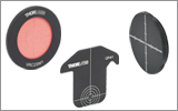 |
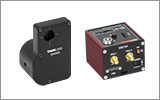 | 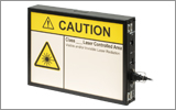 | 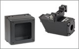 |
安全な作業および安全に関わるアクセサリ
- クラス3または4のレーザを取り扱う場合は、必ずレーザ用保護メガネを装着してください。
- 当社では、レーザのクラスにかかわらず、安全上無視できないパワーレベルのレーザ光線を取り扱う場合は、ネジ回しなどの金属製の器具が偶然に光の方向を変えて再び目に入ってしまうこともあるので、レーザ用保護メガネを必ずご使用いただくようにお勧めしております。
- 特定の波長に対応するように設計されたレーザ保護眼鏡は、装着者を想定外のレーザ反射から保護するために、レーザ装置付近では常に装着してください。
- レーザ保護眼鏡には、保護機能が有効な波長範囲およびその帯域での最小光学濃度が刻印されています。
- レーザ保護カーテンやレーザー安全保護用布は実験室内での高エネルギーレーザの遮光にご使用いただけます。
- 遮光用マテリアルは、直接光と反射光の両方を実験装置の領域に封じ込めて外に逃しません。
- 当社の筺体システムは、その内部に光学セットアップを収納し、レーザ光を封じ込めて危険性を最小限に抑えます。
- ピグテール付き半導体レーザは、他のファイバに接続、もしくは他のファイバとの接続を外す際には、レーザ出力をOFFにしてください。パワーレベルが10 mW以上の場合には特にご注意ください。
- いかなるビーム光も、テーブルの範囲で終端させる必要があります。また、レーザ使用中には、研究室の扉は必ず閉じていなければなりません。
- レーザ光の高さは、目線の高さに設定しないでください。
- 実験は光学テーブル上で、全てのレーザービームが水平を保って直進するように設定してください。
- ビーム光路の近くで作業する人は、光を反射する不要な装飾品やアクセサリ(指輪、時計など)をはずしてください。
- レンズや他の光学装置が、入射光の一部を、前面や背面で反射する場合がありますのでご注意ください。
- あらゆる作業において、レーザは必要最小限のパワーで動作するようにご留意ください。
- アライメントは、可能な限りレーザの出力パワーを低減して作業を行ってください。
- ビームパワーを抑えるためにビームシャッタや フィルタをお使いください。
- レーザのセットアップの近くや実験室には、適切なレーザ標識やラベルを掲示してください。
- クラス3Rやクラス4のレーザ(安全確保用のインターロックが必要となるレーザーレベルの場合)で作業する場合は、警告灯をご用意ください。
- ビームトラップの代用品としてレーザービュワーカードを使用したりしないでください。
レーザ製品のクラス分け
レーザ製品は、目などの損傷を引き起こす可能性に基づいてクラス分けされています。国際電気標準会議(The International Electrotechnical Commission 「IEC」)は、電気、電子工学技術関連分野の国際規格の策定および普及を行う国際機関で、IEC60825-1は、レーザ製品の安全性を規定するIEC規格です。レーザ製品のクラス分けは下記の通りです
| Class | Description | Warning Label |
|---|---|---|
| 1 | ビーム内観察用の光学機器の使用を含む、通常の条件下での使用において、安全とみなされているクラス。このクラスのレーザ製品は、通常の使用範囲内では、人体被害を及ぼすエネルギーレベルのレーザを発光することがないので、最大許容露光量(MPE)を超えることはありません。このクラス1のレーザ製品には、筐体等を開かない限り、作業者がレーザに露光することがないような、完全に囲われた高出力レーザも含まれます。 |  |
| 1M | クラス1Mのレーザは、安全であるが、望遠鏡や顕微鏡と併用した場合は危険な製品になり得ます。この分類に入る製品からのレーザ光は、直径の大きな光や拡散光を発光し、ビーム径を小さくするために光を集束する光学素子やイメージング用の光学素子を使わない限り、通常はMPEを超えることはありません。しかし、光を再び集光した場合は被害が増大する可能性があるので、このクラスの製品であっても、別の分類となる場合があります。 |  |
| 2 | クラス2のレーザ製品は、その出力が最大1 mWの可視域での連続放射光に限定されます。瞬目反射によって露光が0.25秒までに制限されるので、安全と判断されるクラスです。このクラスの光は、可視域(400~700 nm)に限定されます。 |  |
| 2M | このクラスのレーザ製品のビーム光は、瞬目反射があるので、光学機器を通して見ない限り安全であると分類されています。このクラスは、レーザ光の半径が大きい場合や拡散光にも適用されます。 |  |
| 3R | クラス3Rのレーザ製品は、直接および鏡面反射の観察条件下で危険な可視光および不可視光を発生します。特にレンズ等の光学機器を使用しているときにビームを直接見ると、目が損傷を受ける可能性があります。ビーム内観察が行われなければ、このクラスのレーザ製品は安全とみなされます。このクラスでは、MPE値を超える場合がありますが、被害のリスクレベルが低いクラスです。可視域の連続光のレーザの出力パワーは、このレベルでは5 mWまでとされています。 |  |
| 3B | クラス3Bのレーザは、直接ビームを見た場合に危険なクラスです。拡散反射は通常は有害になることはありませんが、高出力のクラス3Bレーザを使用した場合、有害となる場合もあります。このクラスで装置を安全に操作するには、ビームを直接見る可能性のあるときにレーザ保護眼鏡を装着してください。このクラスのレーザ機器にはキースイッチと安全保護装置を設け、さらにレーザ安全表示を使用し、安全照明がONにならない限りレーザがONにならないようにすることが求められます。Class 3Bの上限に近いパワーを出力するレーザ製品は、やけどを引き起こすおそれもあります。 |  |
| 4 | このクラスのレーザは、皮膚と目の両方に損傷を与える場合があり、これは拡散反射光でも起こりうるとみなされています。このような被害は、ビームが間接的に当たった場合や非鏡面反射でも起こることがあり、艶消し面での反射でも発生することがあります。このレベルのレーザ機器は細心の注意を持って扱われる必要があります。さらに、可燃性の材質を発火させることもあるので、火災のリスクもあるレーザであるとみなされています。クラス4のレーザには、キースイッチと安全保護装置が必要です。 |  |
| 全てのクラス2以上のレーザ機器には、上記が規定する標識以外に、この三角の警告標識が表示されていなければいけません。 |  | |
| Posted Comments: | |
| No Comments Posted |