 Products Home / 半導体レーザ用電流コントローラ(LDドライバ)、温度コントローラ、LDマウント / 電流コントローラと温度コントローラ一体型ドライバ / 半導体レーザー/TECコントローラー
半導体レーザー/TECコントローラー
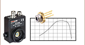
- Provides Laser Currents up to 1 A, 2 A, 5 A, or 20 A
- Supports TEC Currents up to ±8 A or ±15 A
- 17 V and 20 V Compliance Voltage Versions for Driving QCL and ICL Lasers
- Excellent 24 Hour Temperature Stability (0.002 °C)
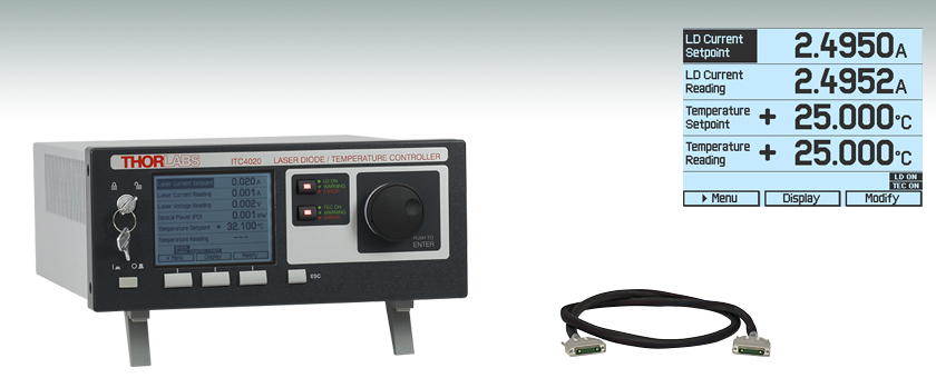
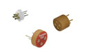
ITC4020
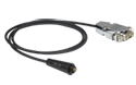
CAB4001
The main measurement display
shows readout values and device
status information.


Please Wait
半導体レーザーコントローラの特長
- アノード接地またはカソード接地の半導体レーザおよびフォトダイオードで動作
- コンプライアンス電圧が17 Vおよび20 Vのタイプでは、高出力な量子カスケードレーザ(QCL)も駆動可能
- 連続発振(CW)または準連続発振(QCW)動作
- LEDも駆動可能
- アナログ変調用に内部ファンクションジェネレータ
- 外部変調用入力端子
- レーザ電流のモニタ用にアナログ出力端子
- 半導体レーザ電圧測定
- アクティブ電源管理による高効率動作
- 適用可能な光学ディテクタ
- フォトダイオード
- サーモパイル
- 一般的なアンプ内蔵センサ
- 電圧出力のパワーメータ
- 半導体レーザの制御モード
- 定電流モード(CC)
- 定光出力モード(CP)
- 強化された半導体レーザの保護機能
- 調整可能なレーザ電流リミット値
- 調整可能なレーザ出力リミット値
- レーザの過電圧保護
- 過温度保護
TECコントローラの特長
- 優れた温度安定性:
0.002 °C (24時間) - 独立にP、I、Dの設定ができる
デジタルPID制御 - 自動PIDチューニング機能
- 調整可能な温度センサーオフセット
- 適用可能な温度センサ
- NTCサーミスタ
- 電流出力型温度センサ
- 電圧出力型温度センサ
- 白金RTD温度センサ
- TECの制御モード
- 定温度モード
- 定電流モード
- 強化されたTECの保護機能
- 調整可能な
TEC電流リミット値 - 調整可能な温度リミット値
- 温度範囲保護機能
- 誤接続ならびにセンサ故障アラーム
| Item #a | ITC4001 | ITC4002QCL | ITC4005 | ITC4005QCL | ITC4020 |
|---|---|---|---|---|---|
| Current Control Range | 0 to 1 A | 0 to 2 A | 0 to 5 A | 0 to 5 A | 0 to 20 A |
| Compliance Voltage | 11 V | 17 Vb | 12 V | 20 Vb | 11 V |
| Photocurrent Measurement Ranges | 2 mA / 20 mA | ||||
| QCWc Mode Pulse Width Range | 100 µs to 1 s | ||||
| QCWc Repetition Rate Range | 1 ms to 5 s (0.2 to 1000 Hz) | ||||
| TEC Current Ranged | -8 to +8 A | -15 to +15 A | |||
| TEC Compliance Voltage | > 12 V | > 15 V | |||
| TEC Output Power (Max) | > 96 W | > 225 W | |||
| Temperature Range (Max) | -150 to +150 °Ce | ||||
| Supported Temperature Sensors | Thermistors (TH10K), Pt100 (TH100PT), Pt1000, AD590, AD592, LM335, LM235, LM135, LM35 | ||||
当社の半導体レーザ/TECコントローラは、半導体レーザーコントローラLDC4000シリーズと温度コントローラTED4015 の機能を1つの装置に組み込んだ製品です。これらのコントローラは、最大電流が1 A~20 Aの半導体レーザ(詳細は右表をご覧ください)に精密かつ安定な電流を供給し、24時間で0.002 °C以内の優れた温度安定性を保ちます。コンプライアンス電圧が11 Vまたは12 Vの標準タイプに加え、量子カスケードレーザ(QCL)ならびにインターバンドカスケードレーザ(ICL)用の高いコンプライアンス電圧を有する2つのドライバをご用意しております。そのうちの1つであるITC4002QCLは2 Aの電流で最大17 Vの電圧を供給でき、もう1つのITC4005QCLは5 Aの電流で最大20 Vの電圧を供給できます。 適切な雑音特性を得るためには、最大定格の電圧、電流がお手持ちのレーザを動作させるうえで必要な電圧、電流に最も近く、かつそれらを超えているコントローラをお選びください。
これらのコントローラは、すべての半導体レーザとモニタ用ダイオードのピン配列に対応しており、定電流(CC)または定光出力(CP)モードの機能を備えております。最も一般的な温度センサがお使いいただけ、またITC4000シリーズはデジタルPIDコントローラによって異なる熱負荷にも対応できます。PIDコントローラには、自動PID設定機能と、P、I、Dパラメータを独立に調整できる機能があります。性能に関する詳細については「追加情報」タブをご覧ください。これらのコントローラは当社のレーザーマウントの製品ラインにも適合します(TEC素子を備えたレーザーマウントの一部にも適合します)。
ITC4000シリーズは、前面パネルキー、および大型で見やすいグラフィックLCD ディスプレイ上の操作メニューによって制御できます(サンプルをご覧になりたい方は「画面表示」タブをご覧ください)。またこれらのコントローラは、SCPI準拠のUSBインターフェイスによっても制御ができます。より高い分解能での設定や測定を行う場合は、前面パネルの分解能が制限されているので、USBを介した操作をお勧めします。また、様々な出力端子やデジタルI/Oポートが付いており、多くの制御や機器接続が可能です。内蔵のファンクションジェネレータにより、レーザ出力のアナログ変調も簡単にできます。
当社では半導体レーザ/TECコントローラ間で安全で信頼性の高い接続が可能なコネクターケーブルをご用意しております。半導体レーザ/TECコントローラ用コネクターケーブルCAB4007AおよびCAB4007Bは高熱負荷(HHL)パッケージ用に設計されています。CAB4007AはコントローラをHHLレーザ用液体冷却式マウントLCM100/Mの接続に特化したケーブルです。CAB4007Bは、標準的な10ピンHHLパッケージを当社のコントローラITC400xQCLに接続するためのケーブルです。LD接続用ケーブルCAB4005とTEC接続用ケーブルCAB4000は、標準的な5Aのコネクターケーブルで、ITC4002QCLとITC4005QCLと共に発送されます。TEC接続用ケーブルCAB4001は、20 Aまでの高電流ケーブルです。
その他にも、準連続発振(QCW)動作モード、容易なPID自動設定、半導体レーザならびにTEC素子の様々な保護機能など、高機能が多数備わっております(詳細については「追加情報」タブをご覧ください)。また、静かで電源効率の良い動作が可能な設計となっております。以上の機能により、ITC4000シリーズは、中出力から高出力の半導体レーザやLEDを、研究室や製造環境において安全かつ確実に動作させるのに適した製品となっています。当社ではこれらのコントローラを24か月ごとに校正することをお勧めしております。当社では再校正サービスを提供しております。詳細は当社までお問い合わせください。
ドライバーソフトウェア、ならびにSCPI、LabVIEW™、Visual C++、Visual C#、Visual Basicのプログラミングリファレンスガイドについては「ソフトウェア」のタブをご覧ください。
| Laser Diode Accessory Selection Guide | |||||
|---|---|---|---|---|---|
| Temperature Controlled Mounts | Passive Mounts | Passive Mounts with Collimation Package | Strain Relief Cables | Diode Sockets | Other Controllers |
 |  |  |  |  |  |
半導体レーザの動作モード
半導体レーザは、お客様が設定したLD電流が正確に保持できる定電流(CC)モード、またはモニタリング用光センサをレーザ出力が能動的に安定化するために用いる定光出力(CP)モードで駆動できます。CCモードでは、最も低いノイズと最も速い応答速度が必要とされる場合に使用されますが、一般的にはこのモードでは温度の安定化も要求されます。光出力一定(CP)モードでは、殆どの半導体レーザーパッケージに内蔵されている内部フォトダイオードもしくは外部フォトダイオードからのフィードバックで、レーザの光出力を能動的に制御します。
20 A ピークの100 µsパルス
図: ITC4020をQCWモードで動作。ピーク電流20.0A、幅100 µsの短パルスをオシロスコープで測定した際のスクリーンショット。
ITC4000シリーズでは、2つの独立したモニタリング用の入力が可能です。1つはフォトダイオードでもう1つはサーモパイルですが、いずれも半導体レーザ制御用に選択していただけます。外部入力、または内蔵のファンクションジェネレータを介したアナログ変調で、半導体レーザをCCとCPモードで変調できます。LD電流に比例した制御用の出力電圧が、モニタリング用に利用されます。
パルス動作
ITC4000シリーズでは、用途によって連続発振(CW)または準連続発振CW(QCW)モードの動作選択が可能です。後者に関しては、QCWモードで動作中のITC4020の出力をオシロスコープでモニタリングした際のスクリーンショットを見ることで、このコントローラーシリーズの品質がわかります。ITC4020は、オーバーシュート無しで容易にシャープで正確なピーク電流20 Aの100 µsパルスを生成します。内蔵のパルス発生器は、内部の可変繰り返し周波数によって、あるいは外部から筐体背面のBNCジャックを介して始動させることができます。
優れた半導体レーザ保護特性
電流リミット: レーザ駆動電流が最大値を超えないように電流リミットは精密調整できます。調整ミスを防ぐために、当社では意識的にこの部分の操作の実行が難しくなるように製品設計しました。予め設定された値より大きなレーザの駆動電流を供給しようとすると、表示と音声で警告します。外部変調機能を利用する場合でも、予め設定された値を超える電流供給はできないようになっています。
電流電源: 電流電源と半導体レーザ間の接続が遮断されると、電流電源は自動的に電流の出力をスイッチOFFします。電流回路がオープンになると、「OPEN」インジケータLEDが赤く点灯し、短い警告音が鳴ります。独立したレーザONキーが、レーザの駆動電流のON/OFFを切り替えます。スイッチがOFFになると、装置内の電子スイッチが、半導体レーザを短絡させて保護します。スイッチがONになった時には、ソフトスタートが実行され、電圧ピーク無しで電流がゆるやかに増大するようになっています。配線に異常が起こっても、レーザ電流は過渡的な影響を受けません。ACラインにおける電圧ピークは、電気フィルタ、トランスの遮蔽と適切な筺体の接地で効率的に抑制できます。
TECコントローラ
ITC4000シリーズには高性能のデジタルTECコントローラが内蔵されており、最大±15 Aまでの電流に対応します。温度の安定性は非常に優れており、24時間、0.002 °C の安定度を維持します。さらにこのシリーズにはTED4015と同様の安全保護機能や操作機能もあります。自動PID機能や独立した調整可能なパラメータによって、デジタルPIDコントローラは様々な熱負荷に対応できます(詳細についてはTED4015をご覧ください)。温度センサ入力部での最大制御範囲は、サーミスタの場合は100 Ω~1 MΩで、プラチナRTDセンサや温度センサICの場合は-55~150 °Cです。実際の適用温度範囲は、接続したセンサや温度関係の設定で決まります。TEC素子を最大限に保護するために、ITCではTED4015と同じ機能が実装されています。いずれの製品にも可変TEC出力電流リミットと温度センサ誤動作警報があります。
ITC4000シリーズでは、実際の温度と設定温度の差に比例したモニタリング信号が供給されます。背面BNCコネクタには、異なる熱負荷で温度が安定化するまでをモニタリングするためにオシロスコープまたははアナログデータ取得カードを接続することができます。
レーザ電流コントローラ
| Item # | ITC4001 | ITC4002QCL | ITC4005 | ITC4005QCL | ITC4020 | |||||
|---|---|---|---|---|---|---|---|---|---|---|
| Front Panela | Remote Controla | Front Panela | Remote Controla | Front Panela | Remote Controla | Front Panela | Remote Controla | Front Panela | Remote Controla | |
| Current Control (Constant Current Mode) | ||||||||||
| Laser Diode Current Range | 0 to 1 A | 0 to 2 A | 0 to 5 A | 0 to 5 A | 0 to 20 A | |||||
| Compliance Voltage | 11 V | 17 V | 12 V | 20 V | 11 V | |||||
| Setting / Measurement Resolution | 100 µA | 16 µA | 100 µA | 32 µA | 1 mA | 80 µA | 1 mA | 80 µA | 1 mA | 320 µA |
| Accuracy | ±(0.1% + 500 µA) | ±(0.1% + 800 µA) | ±(0.1% + 2 mA) | ±(0.1% + 2 mA) | ±(0.1% + 8 mA) | |||||
| Noise and Ripple (10 Hz to 10 MHz, rms, Typ., w/o Noise Reduction Filter) | <10 µA | <20 µA | <250 µA | <250 µA | <10 mA | |||||
| Noise and Ripple (10 Hz to 10 MHz, rms, Typ., w/ Noise Reduction Filter) | <3 µA | <5 µA | <50 µA | <50 µA | N/A | |||||
| Drift, 24 hours (0-10 Hz, typ., at Constant Ambient Temperature) | <100 µA | <150 µA | <300 µA | <300 µA | <1 mA | |||||
| Temperature Coefficient | ≤50 ppm/°C | |||||||||
| Current Limit | ||||||||||
| Setting Range | 1 mA to 1 A | 2 mA to 2 A | 5 mA to 5 A | 5 mA to 5 A | 20 mA to 20 A | |||||
| Setting Resolution | 100 µA | 16 µA | 100 µA | 32 µA | 1 mA | 80 µA | 1 mA | 80 µA | 1 mA | 320 µA |
| Accuracy | ±(0.12% + 800 µA) | ±(0.12% + 1.6 mA) | ±(0.12% + 3 mA) | ±(0.12% + 3 mA) | ±(0.12% + 12 mA) | |||||
| Power Monitor Input - Photodiode | ||||||||||
| Photocurrent Measurement Ranges | 0 to 2 mA / 0 to 20 mA | |||||||||
| Photocurrent Measurement Resolution (2 mA Range / 20 mA Range) | 1 µA / 10 µA | 32 nA / 320 nA | 1 µA / 10 µA | 32 nA / 320 nA | 1 µA / 10 µA | 32 nA / 320 nA | 1 µA / 10 µA | 32 nA / 320 nA | 1 µA / 10 µA | 32 nA / 320 nA |
| Photocurrent Accuracy (2 mA Range / 20 mA Range) | ±(0.08% +0.5 µA) / ±(0.08% +5 µA) | |||||||||
| Photodiode Reverse Bias Voltage | 0 to 10 V | |||||||||
| Photodiode Input Impedance | ~0 Ω (Virtual Ground) | |||||||||
| Power Monitor Input - Thermopileb | ||||||||||
| Voltage Measurement Ranges | 0 to 10 mV / 0 to 100 mV / 0 to 1V / 0 to 10V | |||||||||
| Voltage Measurement Resolution (for 10 mV, 100 mV, 1 V, 10 V Range) | 1 µV 10 µV 100 µV 1 mV | 0.16 µV 1.6 µV 16 µV 160 µV | 1 µV 10 µV 100 µV 1 mV | 0.16 µV 1.6 µV 16 µV 160 µV | 1 µV 10 µV 100 µV 1 mV | 0.16 µV 1.6 µV 16 µV 160 µV | 1 µV 10 µV 100 µV 1 mV | 0.16 µV 1.6 µV 16 µV 160 µV | 1 µV 10 µV 100 µV 1 mV | 0.16 µV 1.6 µV 16 µV 160 µV |
| Voltage Measurement Accuracy (for 10 mV / 100 mV / 1V / 10 V Range) | ±(0.1% + 10 µV) / ±(0.1% + 100 µV) / ±(0.1% + 1 mV) / ±(0.1% + 5 mV) | |||||||||
| Voltage Input Impedance | 1 MΩ | |||||||||
| Laser Power Control (Constant Power Mode) | ||||||||||
| Photocurrent Control Rangesc | 0 to 2 mA / 0 to 20 mA | |||||||||
| Photocurrent Setting Resolution | 1 µA / 10 µA | 32 nA / 320 nA | 1 µA / 10 µA | 32 nA / 320 nA | 1 µA / 10 µA | 32 nA / 320 nA | 1 µA / 10 µA | 32 nA / 320 nA | 1 µA / 10 µA | 32 nA / 320 nA |
| Thermopile Voltage Control Rangesc | 1 µV to 10 mV / 10 µV to 100 mV / 100 µV to 1V / 1 mV to 10V | |||||||||
| Thermopile Voltage Setting Resolution | 1 µV 10 µV 100 µV 1 mV | 0.16 µV 1.6 µV 16 µV 160 µV | 1 µV 10 µV 100 µV 1 mV | 0.16 µV 1.6 µV 16 µV 160 µV | 1 µV 10 µV 100 µV 1 mV | 0.16 µV 1.6 µV 16 µV 160 µV | 1 µV 10 µV 100 µV 1 mV | 0.16 µV 1.6 µV 16 µV 160 µV | 1 µV 10 µV 100 µV 1 mV | 0.16 µV 1.6 µV 16 µV 160 µV |
| Power Limit (Constant Power Mode) | ||||||||||
| Photocurrent Limit Setting Rangesc | 5 µA to 2 mA / 50 µA to 20 mA | |||||||||
| Photocurrent Limit Resolution (2 mA Range/ 20 mA Range) | 1 µA / 10 µA | 128 nA / 1.28 µA | 1 µA / 10 µA | 128 nA / 1.28 µA | 1 µA / 10 µA | 128 nA / 1.28 µA | 1 µA / 10 µA | 128 nA / 1.28 µA | 1 µA / 10 µA | 128 nA / 1.28 µA |
| Photocurrent Limit Accuracy | ±20 µA / ±200 µA | |||||||||
| Thermopile Voltage Limit Setting Rangesc | 1 µV to 10 mV / 10 µV to 100 mV / 100 µV to 1V / 1 mV to 10V | |||||||||
| Thermopile Voltage Limit Resolution | 1 µV 10 µV 100 µV 1 mV | 730 nV 7.3 µV 73 µV 730 µV | 1 µV 10 µV 100 µV 1 mV | 730 nV 7.3 µV 73 µV 730 µV | 1 µV 10 µV 100 µV 1 mV | 730 nV 7.3 µV 73 µV 730 µV | 1 µV 10 µV 100 µV 1 mV | 730 nV 7.3 µV 73 µV 730 µV | 1 µV 10 µV 100 µV 1 mV | 730 nV 7.3 µV 73 µV 730 µV |
| Thermopile Voltage Limit Accuracy | ±10 µV / ±100 µV / ±1 mV / ±10 mV | |||||||||
| Item # | ITC4001 | ITC4002QCL | ITC4005 | ITC4005QCL | ITC4020 | |||||
| Front Panela | Remote Controla | Front Panela | Remote Controla | Front Panela | Remote Controla | Front Panela | Remote Controla | Front Panela | Remote Controla | |
| Laser Voltage Measurement | ||||||||||
| Measurement Principle | 4-Wire | |||||||||
| Measurement Resolution | 1 mV | 160 µV | 1 mV | 320 µV | 1 mV | 160 µV | 1 mV | 320 µV | 1 mV | 160 µV |
| Accuracy | ±20 mV | ±30 mV | ±20 mV | ±30 mV | ±20 mV | |||||
| Laser Overvoltage Protection | ||||||||||
| Setting Range | 1 V to 11 V | 1 V to 17 V | 1 V to 12 V | 1 V to 20 V | 1 V to 11 V | |||||
| Resolution | 1 mV | |||||||||
| Accuracy | ±50 mV | ±70 mV | ±50 mV | ±70 mV | ±50 mV | |||||
| Laser Current Monitor Output | ||||||||||
| Load Resistance | >10 kΩ | |||||||||
| Transmission Coefficient | 10 V/A ±5% | 5 V/A ± 5% | 2 V/A ±5% | 2 V/A ±5% | 500 mV/A ±5% | |||||
| External Modulation Input | ||||||||||
| Input Impedance | 10 kΩ | |||||||||
| Small Signal 3dB Bandwidth, CC Mode w/o Noise Reduction Filter | DC to 150 kHz (2 Ω Load) | DC to 130 kHz (2 Ω Load) | DC to 100 kHz (1 Ω Load) | DC to 100 kHz (1 Ω Load) DC to 50 kHz (5 Ω Load) | DC to 50 kHz (0.2 Ω Load) | |||||
| Small Signal 3dB Bandwidth, CC Mode w/ Noise Reduction Filter | DC to 10 kHz (2 Ω Load) | DC to 10 kHz (2 Ω Load) | DC to 6 kHz (1 Ω Load) | DC to 6 kHz (1 Ω Load) DC to 5 kHz (5 Ω Load) | N/A | |||||
| Modulation Coefficient, CC Mode | 100 mA/V ±5% | 200 mA/V ± 5% | 500 mA/V ±5% | 500 mA/V ±5% | 2A/V ±5% | |||||
| Modulation Coefficient, CP Mode, Current Sensorc | 200 µA/V / 2 mA/V ±5% | |||||||||
| Modulation Coefficient, CP Mode, Voltage Sensorc | 1 mV/V / 10 mV/V / 100 mV/V / 1V/V ±5% | |||||||||
| Internal Laser Modulation | ||||||||||
| Waveforms | Sine, Square, Triangle | |||||||||
| Frequency Range | 20 Hz to 150 kHz | 20 to 130 kHz | 20 Hz to 100 kHz | 20 Hz to 100 kHz | 20 Hz to 50 kHz | |||||
| Modulation Depth | 0.1 to 100% | |||||||||
| QCW Mode | ||||||||||
| Pulse Width Range | 100 µs to 1 s | |||||||||
| Pulse Width Resolution | 1 µs | |||||||||
| Repetition Rate Range | 1 ms to 5 s (0.2 to 1000 Hz) | |||||||||
| Repetition Rate Resolution | 10 µs | |||||||||
| Trigger | ||||||||||
| Input | Rising Edge Triggered, Starts QCW Pulse with Internal Adjusted Width | |||||||||
| Input Level | TTL or 5 V CMOS | |||||||||
| Output | Active High, Tracks Pulse Width | |||||||||
| Output Level | TTL or 5 V CMOS | |||||||||
| Dead Time to Next Pulse | >10 µs | |||||||||
全ての技術データは、温度23±5°C、相対湿度45±15%の条件下で有効です。なお、予告なしに変更される場合があります。
温度制御
| Item # | ITC4001 | ITC4002QCL | ITC4005 | ITC4005QCL | ITC4020 | |||||
|---|---|---|---|---|---|---|---|---|---|---|
| Front Panela | Remote Controla | Front Panela | Remote Controla | Front Panela | Remote Controla | Front Panela | Remote Controla | Front Panela | Remote Controla | |
| TEC Current Control | ||||||||||
| Control Range | -8 to +8 A | -15 to +15 A | ||||||||
| Compliance Voltage | >12 V | >15 V | ||||||||
| Maximum Output Power | >96 W | >225 W | ||||||||
| Resolution, CC Mode | 1 mA | 0.1 mA | 1 mA | 0.1 mA | 1 mA | 0.1 mA | 1 mA | 0.1 mA | 1 mA | 0.1 mA |
| Accuracy | ±(0.2% + 20 mA) | |||||||||
| Noise and Ripple typ. | <10 mA rms | |||||||||
| TEC Current Limit | ||||||||||
| Setting Rangeb | 0.1 A to 8 A | 0.1 A to 15 A | ||||||||
| Resolution | 1 mA | 0.1 mA | 1 mA | 0.1 mA | 1 mA | 0.1 mA | 1 mA | 0.1 mA | 1 mA | 0.1 mA |
| Accuracy | ±(0.2% + 10 mA) | |||||||||
| NTC Thermistor Sensors | ||||||||||
| Resistance Measurement Ranges | 100 Ω to 100 kΩ / 1 kΩ to 1 MΩ | |||||||||
| Control Range Maxc | -150 to +150 °C | |||||||||
| Temperature Resolution | 0.001 °C | |||||||||
| Resolution (Resistance, 100 kΩ / 1 MΩ Range) | 0.1 Ω / 1 Ω | 0.03 Ω / 0.3 Ω | 0.1 Ω / 1 Ω | 0.03 Ω / 0.3 Ω | 0.1 Ω / 1 Ω | 0.03 Ω / 0.3 Ω | 0.1 Ω / 1 Ω | 0.03 Ω / 0.3 Ω | 0.1 Ω / 1 Ω | 0.03 Ω / 0.3 Ω |
| Accuracy (100 kΩ / 1 MΩ Range) | ±(0.06% + 1 Ω / 5 Ω) | |||||||||
| Temperature Stability (24 Hours Typical)c | <0.002 °C | |||||||||
| Temperture Coefficient | <5 mK/°C | |||||||||
| IC Sensors | ||||||||||
| Supported Current Temperature Sensors | AD590, AD592 | |||||||||
| Supported Voltage Temperature Sensors | LM335, LM235, LM135, LM35 | |||||||||
| Control Range with AD590 | -55 to +150 °C | |||||||||
| Control Range with AD592 | -25 to +105 °C | |||||||||
| Control Range with LM335 | -40 to +100 °C | |||||||||
| Control Range with LM235 | -40 to +125 °C | |||||||||
| Control Range with LM135 | -55 to +150 °C | |||||||||
| Control Range with LM35 | -55 to +150 °C | |||||||||
| Resolution | 0.001 °C | 0.0001 °C | 0.001 °C | 0.0001 °C | 0.001 °C | 0.0001 °C | 0.001 °C | 0.0001 °C | 0.001 °C | 0.0001 °C |
| Accuracy AD590 Current | ± (0.04% + 0.08 µA) | |||||||||
| Accuracy LM335/LM35 Voltage | ± (0.03% + 1.5 mV) | |||||||||
| Temperature Stability (24 hours) | <0.002 °C | |||||||||
| Temperature Coefficient | <5 mK/°C | |||||||||
| Item # | ITC4001 | ITC4005 | ITC4005QCL | ITC4020 | ||||||
| Front Panela | Remote Controla | Front Panela | Remote Controla | Front Panela | Remote Controla | Front Panela | Remote Controla | Front Panela | Remote Controla | |
| Pt100/Pt1000 RTD Sensors | ||||||||||
| Temperature Control Range | -55 to +150 °C | |||||||||
| Resolution | 0.001 °C | 0.0003 °C | 0.001 °C | 0.0003 °C | 0.001 °C | 0.0003 °C | 0.001 °C | 0.0003 °C | 0.001 °C | 0.0003 °C |
| Accuracy (4-Wire Measurement) | ±0.3 °C | |||||||||
| Temperature Stability (24 Hours) | <0.005 °C | |||||||||
| Temperature Coefficient | <20 mK/°C | |||||||||
| Temperature Window Protection | ||||||||||
| Setting Range Twin | 0.01 to 100.0 °C | |||||||||
| Protection Reset Delay | 0 to 600 s | |||||||||
| Window Protection Output | TTL or 5 V CMOS | |||||||||
| Temperature Control Output | ||||||||||
| Load Resistance | >10 k Ω | |||||||||
| Transmission Coefficient | ΔT * 5V / Twin ±0.2 % (Temperature Deviation, Scaled to Temperature Window) | |||||||||
| TEC Voltage Measurement | ||||||||||
| Measurement Principle | 4-Wire/2-Wire | |||||||||
| Resolution | 100 mV | 40 mV | 100 mV | 40 mV | 100 mV | 40 mV | 100 mV | 40 mV | 100 mV | 40 mV |
| Accuracy (with 4-Wire Measurement) | ±50 mV | |||||||||
全ての技術データは、温度23±5°C、相対湿度45±15%の条件下で有効です。なお、予告なしに変更される場合があります。
一般的な仕様
| Item # | ITC4001 | ITC4002QCL | ITC4005 | ITC4005QCL | ITC4020 | |||||||
|---|---|---|---|---|---|---|---|---|---|---|---|---|
| Digital I/O Port | ||||||||||||
| Number of I/O lines | 4 (Separately Configurable) | |||||||||||
| Input Level | TTL or CMOS, Voltage Tolerant up to 24 V | |||||||||||
| Output Level (Source Operation) | TTL or 5 V CMOS, 2 mA Max | |||||||||||
| Output Level (Sink Operation) | Open Collector, up to 24 V, 400 mA Max | |||||||||||
| Interface | ||||||||||||
| USB 2.0 | According to USBTMC/USBTMC-USB488 Specification Rev. 1.0 | |||||||||||
| Protocol | SCPI Compliant Command Set | |||||||||||
| Drivers | VISA VXIpnp™, MS Visual Studio™, MS Visual Studio.net™, NI LabVIEW™, NI LabWindows/CVI™ | |||||||||||
| General Data | ||||||||||||
| Safety Features | Interlock, Inhibit, Keylock Switch, Laser Current Limit, Laser Power Limit, Soft Start, Short Circuit when Laser Off, Adjustable Laser Overvoltage Protection, Over Temperature Protection Temperature Window Protection | |||||||||||
| Display | LCD 320 x 240 Pixel | |||||||||||
| Connector for Laser, Photodiode, Interlock, and Laser On Signal | 13W3 Mixed D-Sub Jack (female) | |||||||||||
| Connector for Sensor, TE Cooler, TEC On Signal | 17W2 Mixed D-Sub Jack (female) | |||||||||||
| Connectors for Control Input / Output | BNC | |||||||||||
| Connector for Digitial I/O | Mini DIN 6 | |||||||||||
| Connector for USB-Interface | USB Type B | |||||||||||
| Chassis Ground Connector | 4 mm Banana Jack | |||||||||||
| Line Voltage / Frequency | 100 to 120 V and 200 to 240 V ±10%, 50 to 60 Hz | |||||||||||
| Maximum Power Consumption | 300 VA | 600 VA | 650 VA | 880 VA | 900 VA | |||||||
| Mains Supply Overvoltage | Category II (Cat II) | |||||||||||
| Operating Temperature | 0 to 40 °C | |||||||||||
| Storage Temperature | - 40 to +70 °C | |||||||||||
| Relative Humidity | Max. 80% Up to 31 °C, Decreasing to 50% at 40 °C | |||||||||||
| Pollution Degree (Indoor Use Only) | 2 | |||||||||||
| Operation Altitude | <2000 m | |||||||||||
| Warm-up Time for Rated Accuracy | 30 min | |||||||||||
| Weight | 6.4 kg | |||||||||||
| Dimensions w/o Operating Elements (W x H x D) | 263 mm x 122 mm x 307 mm (10.4" x 4.8" x 12.1") | |||||||||||
| Dimensions /w Operating Elements (W x H x D) | 263 mm x 122 mm x 345 mm (10.4" x 4.8" x 13.6") | |||||||||||
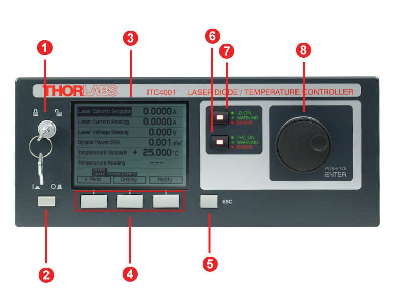
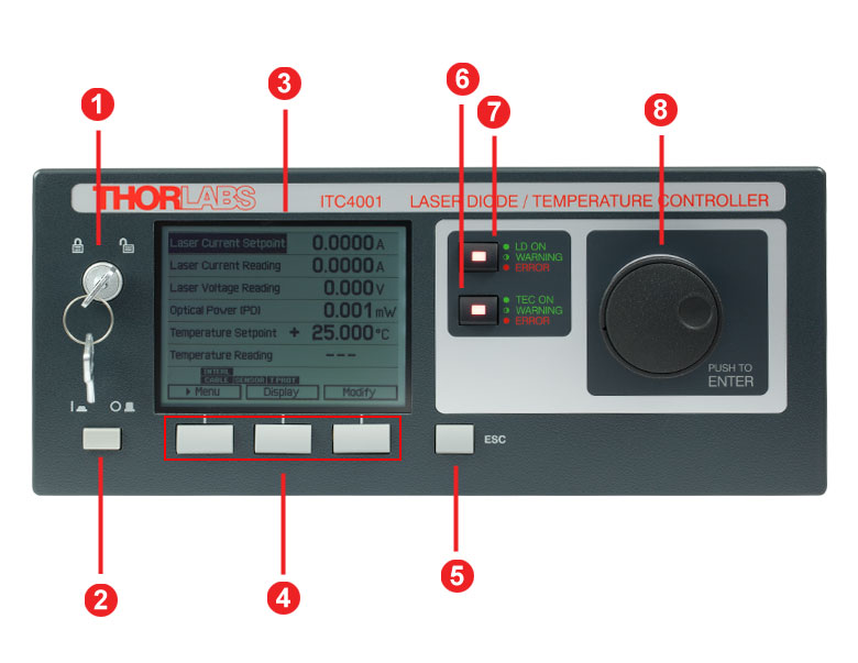
ITC4000シリーズ前面パネル
| Callout | Connection | Callout | Connection |
|---|---|---|---|
| 1 | Key Switch | 5 | Escape Key |
| 2 | Supply Power Switch | 6 | TEC Status Indicator |
| 3 | LC Display | 7 | LD Status Indicator |
| 4 | Softkeys for Menu Navigation | 8 | Adjustment Knob |
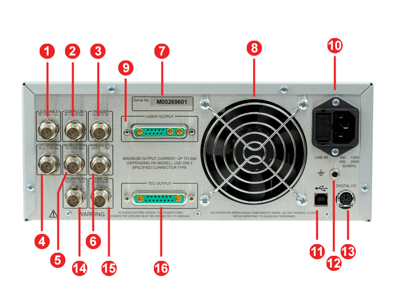
ITC4000シリーズ背面パネル
| Callout | Connection | Callout | Connection |
|---|---|---|---|
| 1 | TTL Input "Laser Enable In" 5 V Max | 9 | LD Output and Optical Sensor Input "Laser Output" |
| 2 | TTL Input "QCW Pulse In" 5 V Max | 10 | Power Connector and Fuse Holder "Line In" |
| 3 | TTL Output "Trigger Out" 0 - 5 V | 11 | USB Connector |
| 4 | Optical Sensor Input "Opt Sensor In" 0 to 10 V Max | 12 | 4 mm Banana Jack for Chassis Ground |
| 5 | Modulation input "Modulation In" -10 to 10 V | 13 | MiniDin-6 Jack "Digital I/O" |
| 6 | Laser Current Monitor "Analog CTL Out" 0 - 10 V | 14 | Actual Temperature Deviation Output "Deviation Out" -5 to 5 V |
| 7 | Serial Number of the Unit | 15 | TTL Temperature Monitor Output "Temp OK Out" 5 V |
| 8 | Cooling Fan | 16 | TEC Element Output and Temperature Sensor Input "TEC Output" |
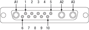
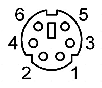
半導体レーザ出力端子
13W3 Mixed D-Subジャック
| Pin | Connection | Pin | Connection |
|---|---|---|---|
| 1 | (Thermo) Voltage Sensor Input (+) | 7 | Photo Current Sensor Input (+) |
| 2 | (Thermo) Voltage Sensor Ground (-) | 8 | Photo Current Sensor Ground (-) |
| 3 | Not Connected | 9 | Not Connected |
| 4 | Laser Diode Anode (+) | 10 | Laser Diode Cathode (-) |
| 5 | Output for Interlock and Status Indicator "LASER ON/OFF" (+) | A1 | Laser Diode Ground |
| 6 | Ground Pin for Interlock and Status Indicator "LASER ON/OFF" (-) | A2 | Laser Diode Cathode (with Polarity AG) (-) |
| A3 | Laser Diode Anode (with Polarity CG) (+) |
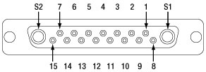
TEC出力端子
17W2 Mixed D-Subジャック
| Pin | Connection | Pin | Connection |
|---|---|---|---|
| 1 | Interlock, TEC ON LED (+) | 10 | PT100/1000 (-), AD590/592 (-), LM35 Out, LM135/235/335 (+) |
| 2 | Voltage Measurement TEC Element (+) | 11 | PT100/1000 (+), AD590/592 (+), LM35/135/235/335 (+) |
| 3 | Thermistor (-), PT100/1000 (-), Analog Ground | 12 | Analog Ground, LM35/135/235/335 (-) |
| 4 | Thermistor (+), PT100/1000 (+) | 13 | Not Connected |
| 5 | Analog Ground, LM35/135/235/335 (-) | 14 | I/O 1-wire (Currently Not Used) |
| 6 | Digital Ground for I/O 1-Wire | 15 | Ground for 12 V Output and Interlock, TEC ON LED (-) |
| 7 | 12 V Output (for External Fan, Max. Current = 500 mA) | S1 | TEC Element (+) (Peltier Element) |
| 8 | Not Connected | S2 | TEC Element (-) (Peltier Element) |
| 9 | Voltage Measurement TEC Element (-) |
デジタル I/Oポート
| Pin | Connection |
|---|---|
| 1 | I/O 1 |
| 2 | I/O 2 |
| 3 | I/O 3 |
| 4 | I/O 4 |
| 5 | GND |
| 6 | I/O Supply Voltage (+12 V from Internal or Higher External Voltage up to +24 V) |
LD Enable入力端子
BNC メス型
レーザをEnableにする信号入力(HighでレーザON)、TTL 5 V Max
準連続発振(QCW)パルス入力端子
BNC メス型
外部トリガ信号入力、TTL 5 V Max
トリガ出力端子
BNC メス型
準連続発振(QCW)パルストラッキング出力、TTL 5 V
光学センサ入力端子
BNC メス型
光学センサ用入力、0~+10 V Max
変調入力端子
BNC メス型
外部変調信号用入力、 -10~+10 V Max
アナログCTL出力端子
BNC メス型
レーザ電流モニタ用出力、0~+10 V
温度差分出力端子
BNC メス型
実際の温度差分出力、 -5~+5 V
温度OK出力端子
BNC メス型
温度OK信号出力(温度ウィンドウの中であればHigh)、TTL 5 V
コンピュータ接続
USB B型
USBのB型-A型変換ケーブルが付属します。
グラウンド

シャーシグラウンド用4 mmバナナジャック
半導体レーザーケーブルCAB4005
このケーブルの一端にはDB-9オス型コネクタ、もう一端には13W3オス型コネクタが付いております。 下の両図はコネクタのピン配列となっております。
DB-9 オス型コネクタ
| Pin | Color |
| 1 | White |
| 2 | Gray and Pink |
| 3 | Gray / Blacka |
| 4 | Red and Blue |
| 5 | Brown |
| 6 | Blue |
| 7 | Yellow / Purplea |
| 8 | Green / Pinka |
| 9 | Red |
13W3 オス型コネクタ
| 13W3 Connector Colors | |||
|---|---|---|---|
| Pin | Color | Pin | Color |
| 1 | No Connection | 9 | No Connection |
| 2 | No Connection | 10 | Blue |
| 3 | No Connection | A1 | Gray / Blacka |
| 4 | Red | ||
| 5 | White | A2 | Yellow / Purplea |
| 6 | Brown | ||
| 7 | Red and Blue | A3 | Green / Pinka |
| 8 | Gray and Pink | ||
| Pin Matching | ||
|---|---|---|
| DB-9 Pin | 13W3 Pin | Description of ITC Functionality |
| 1 | 5 | Output for Interlock and Status Indicator "LASER ON/OFF" (+) |
| 2 | 8 | Photo Current Sensor Ground (-) |
| 3 | A1 | Laser Diode Ground |
| 4 | 7 | Photo Current Sensor Input (+) |
| 5 | 6 | Ground Pin for Interlock and Status Indicator "LASER ON/OFF" (-) |
| 6 | 10 | Laser Diode Cathode (-) |
| 7 | A2 | Laser Diode Cathode (with Polarity AG) (-) |
| 8 | A3 | Laser Diode Anode (with Polarity CG) (+) |
| 9 | 4 | Laser Diode Anode (+) |
| Shield | Shield | - |
TEC素子ケーブルCAB4000
このケーブルの一端にはDB-9メス型コネクタ、もう一端には17W2オス型コネクタが付いております。 下の両図はコネクタのピン配列となっております。
DB-9 メス型コネクタ
17W2 オス型コネクタ
| DB-9 Connector Colors | |
|---|---|
| Pin | Color |
| 1 | White |
| 2 | Pink and Gray |
| 3 | Red and Blue |
| 4 | Pink / Red / Purple (3 Wires) |
| 5 | Black / Gray / Blue (3 Wires) |
| 6 | No Connection |
| 7 | Yellow |
| 8 | Brown |
| 9 | Green |
| 17W2 Connector Colors | |||
|---|---|---|---|
| Pin | Color | Pin | Color |
| 1 | White | 11 | Green |
| 2 | Red | 12 | Brown |
| 3 | Red and Blue | 13 | No Connection |
| 4 | Pink and Gray | 14 | No Connection |
| 5 | Brown | 15 | White |
| 6 | No Connection | S1 | Purple / Pink (2 Wires) |
| 7 | No Connection | ||
| 8 | No Connection | S2 | Black / Gray (2 Wires) |
| 9 | Blue | ||
| 10 | Yellow | ||
| Pin Matching | ||
|---|---|---|
| DB-9 Pin | 17W2 Pin(s) | Description of ITC Functionality |
| 1 | 1 | Interlock, TEC ON LED (+) |
| 15 | Ground for 12 V Output and Interlock, TEC ON LED (-) | |
| 2 | 4 | Thermistor (+), PT100/1000 (+) |
| 3 | 3 | Thermistor (-), PT100/1000 (-), Analog Ground |
| 4 | 2 | Voltage Measurement TEC Element (+) |
| S1 | TEC Element (+) (Peltier Element) | |
| 5 | 9 | Voltage Measurement TEC Element (-) |
| S2 | TEC Element (-) (Peltier Element) | |
| 6 | No Connection | - |
| 7 | 10 | PT100/1000 (-), AD590/592 (-), LM35 Out, LM135/235/335 (+) |
| 8 | 5 | Analog Ground, LM35/135/235/335 (-) |
| 12 | Analog Ground, LM35/135/235/335 (-) | |
| 9 | 11 | PT100/1000 (+), AD590/592 (+), LM35/135/235/335 (+) |
| Shield | Shield | - |
レーザ/TECケーブルCAB4007A
このケーブルは柔軟性の高いフラットケーブルで構成されており、片端には9W4オス型コネクタ、もう一方には17W2および13W3オス型コネクタが付いています。CAB4007Aは液体冷却式マウントLCM100/Mと当社のITC400xQCLシリーズコントローラの接続にご使用いただけます。

17W2オス型コネクタ
13W3オス型コネクタ
9W4オス型コネクタ
| CAB4007A | ||||
|---|---|---|---|---|
| 9W4 Pin | Signal | 13W3 Pin | 17W2 Pin | Max Current Input |
| A4 | TEC Cathode (-) | No Connection | A2 | 11 A |
| 2 | No Connection | No Connection | No Connection | 5 A |
| A3 | Laser Diode Anode (+) | A3 | No Connection | 11 A |
| 1 | Thermistor (+) | No Connection | 4 | 5 A |
| 3 | Thermistor (-) | No Connection | 3 | 5 A |
| A2 | Laser Diode Cathode (-) | A2 | No Connection | 11A |
| 4 | EEPROM (+) | 3 | No Connection | 5 A |
| 5 | EEPROM (- / Ground) | 9 | No Connection | 5 A |
| A1 | TEC Anode (+) | No Connection | A1 | 11 A |
| No Connection | Laser Driver Interlock | 5, 6 | No Connection | - |
| No Connection | TEC Driver Interlock | No Connection | 1, 15 | - |
レーザ/TECケーブルCAB4007B
このケーブルは柔軟性の高いフラットケーブルで構成されており、片端にはフラット10ピンHHLメス型コネクタ、もう一方には17W2および13W3オス型コネクタが付いています。CAB4007Bは、フラット10ピンHHLメス型コネクタが付いたあらゆるレーザと当社のITC400xQCLシリーズコントローラの接続にご使用いただけます。
17W2オス型コネクタ

13W3オス型コネクタ
10 ピンフラットメス型コネクタ
| CAB4007B | ||||
|---|---|---|---|---|
| Flat 10-Pin HHL Connector | Signal | 13W3 Pin | 17W2 Pin | Max Current Input |
| 1 | TEC Cathode (-) | No Connection | A2 | 10 A |
| 3 | No Connection | No Connection | No Connection | 5 A |
| 4 | Laser Diode Anode (+) | A3 | No Connection | 10 A |
| 5 | Thermistor (+) | No Connection | 4 | 5 A |
| 6 | Thermistor (-) | No Connection | 3 | 5 A |
| 7 | Laser Diode Cathode (-) | A2 | No Connection | 10 A |
| 8 | EEPROM (+) | 3 | No Connection | 5 A |
| 9 | EEPROM (- / Ground) | 9 | No Connection | 5 A |
| 10 | TEC Anode (+) | No Connection | A1 | 10 A |
| No Connection | Laser Driver Interlock | 5, 6 | No Connection | - |
| No connection | TEC Driver Interlock | No Connection | 1, 15 | - |
ITC4000シリーズのサンプル画面
| 測定画面1 | 測定画面2 | ||
|---|---|---|---|
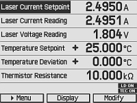 | 測定画面では、測定値やデバイスの状態について簡単に確認することができます。 この画面で機器の主要な設定値も調整することができます。 ご希望の文字サイズで2つ、4つ、6つの情報を選んで表示することができます。 |  | この測定画面は2つの情報を表示するよう設定されています。 文字サイズは簡単に読めるよう最大化しています。 |
| メニュー画面 | 準連続発振設定画面 | ||
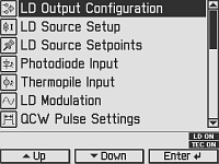 | メニュー画面では、様々な動作モードや選択肢を選ぶことができます。 | 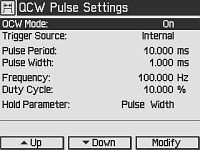 | この画面は準連続発振(QCW)パルスモード設定の入力画面で、設定には例えばトリガ光源やパルスのパラメータなどがあります。 |
| 半導体レーザ設定画面 | フォトダイオード入力画面 | ||
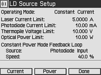 | 半導体レーザ設定画面では、定電流または定光出力モードの設定、レーザ電流ならびに出力のリミット値、また定光出力フィードバックループの速度と、光源などレーザ制御に必要な以下のパラメータを入力することができます。 | 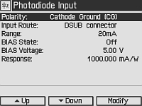 | フォトダイオードセンサに関するパラメータはすべてこのフォトダイオード入力画面から入力します。 |
| 温度コントローラ画面 | 温度モード設定画面 | ||
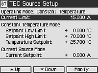 | 動作モード、電流リミット値、電流制御モード設定、温度センサ設定の温度コントローラのパラメータはすべて温度コントローラ画面から入力します。 | 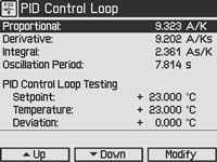 | 手動による最適化の場合、温度のPID制御ループ設定はこの画面から入力します。 温度の設定値と実際値がご覧になれるのでテストに便利です。 |
| PID自動設定画面 | 設定画面 | ||
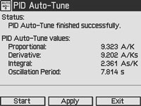 | PID自動設定機能はこの画面から起動させます。 ITC4000シリーズは、現時点の温度設定に適したPIDのパラメータを自動的に選択します。 | 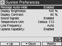 | 設定画面では、例えば画像表示や信号の設定画面などの機器設定をご覧いただけます。 |
半導体レーザーコントローラ用ソフトウェア
下図のダウンロードボタンのリンク先には、VISA VXI pnp™、MS Visual Studio™、MS Visual Studio.net™、LabVIEW™および LabWindows/CVI™のドライバ、ファームウェア、ユーティリティ、そしてITC4000シリーズのレーザーコントローラと、LDC4000シリーズのレーザーコントローラ、小型LDコントローラCLD1000シリーズ、TED4000シリーズのTECコントローラに関連したサポートドキュメントがあります。
ソフトウェアのダウンロードページには、SCPI、LabVIEW、Visual C++、Visual C#、Visual Basicを使用して様々なコントローラを結合させるリファレンスプログラミングノートもご用意しております。 詳細やリンク先についてはソフトウェアダ ウンロードページの「Programming Reference」のタブをご覧ください。
ドライバーソフトウェア
バージョン3.1.0 (2014年4月11日)
プログラミングリファレンス
バージョン3.3 (2015年4月8日) - SCPIコマンド
バージョン1.0 (2015年6月16日) - LabVIEW、Visual C++、Visual C#、Visual Basic
これらのソフトウェアパッケージは、LabVIEWのバージョン8.5以降をサポートします。 お手元のLabVIEWがそれ以前のバージョンの場合は、当社までご相談ください。
| Item # | ITC4001 | ITC4002QCL | ITC4005 | ITC4005QCL | ITC4020 |
|---|---|---|---|---|---|
| Components | |||||
| Benchtop Laser Diode/TEC Controller, 1 A / 96 W | - | - | - | - | |
| Benchtop Laser Diode/TEC Controller, 2 A / 225 W with 17 V Compliance for QCLs | - | - | - | ||
| Benchtop Laser Diode/TEC Controller, 5 A / 225 W | - | - | - | - | |
| Benchtop Laser Diode/TEC Controller, 5 A / 225 W with 20 V Compliance for QCLs | - | - | - | - | |
| Benchtop Laser Diode/TEC Controller, 20 A / 225 W | - | - | - | - | |
| Cable TED4000/ITC4000 to Laser Mount, 5 A, 17W2, D-Sub-9 (CAB4000) | - | ||||
| Cable TED4000/ITC4000 to Laser Mount, 20 A, 17W2, 17W2 (CAB4001) | - | - | - | - | |
| Cable LDC4000/ITC4000 to Laser Mount, 5 A, 13W3, D-Sub-9 (CAB4005) | - | ||||
| Cable LDC4000/ITC4000 to Laser Mount, 20 A, 13W3, 13W3 (CAB4006) | - | - | - | - | |
| Mixed D-Sub Connector, 17W2, Male & Female with 2 High-Current Contacts Each, 20 A (CON4001) | |||||
| Mixed D-Sub Connector, 13W3, Male & Female with 3 High-Current Contacts Each, 20 A (CON4005) | |||||
| USB Cable A-B, 2 m | |||||
| 4000 Series Instrumentation CD | |||||
| ITC4000 Series Printed Operation Manual | |||||
| Certificate of Calibration | |||||
PIDの基礎
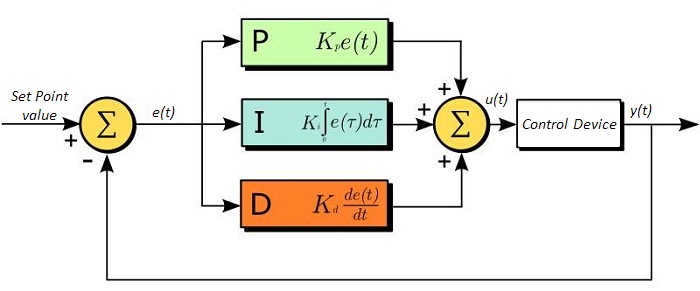
PID回路は制御ループフィードバックコントローラとしてよく用いられており、さまざまなサーボ回路として広く使われています。 PIDとは、それぞれ比例(Proportional)、積分(Integral)、微分(Derivative)の頭文字で、PID回路の3つの制御設定を表しています。 サーボ回路の役割は、システムを長時間所定値(目標値)に保持することです。 PID回路は、出力を目標値に保持するため、主に目標値と出力値の差をエラー信号として発生させることにより、システムをアクティブ制御しています。 3つの制御は、時間依存型エラー信号に関連しています; 端的に言うと、次のように考えることができます。 比例は出力値のエラー、積分は過去の累積エラー、微分はエラーの予測によっています。 各制御の結果は、その後回路の電流を調整する加重和にフィードされます(u(t))。 この出力は制御デバイスへ送られ、その値は回路へとフィードバックされ、回路の出力を目標値に到達させ保持するようアクティブ安定化の処理が行われます。 以下のブロック図は、PID回路の動作を簡略化したものです。 システム要求や要件によって、サーボ回路に1つもしくは複数の制御を使用することができます(例: P、I、PI、PD、PID)。
PID回路の適正な制御設定によって、最小限のオーバーシュート(目標値超過)とリンギング(目標値振動)で、素早い応答速度を実現できます。 ここで半導体レーザの温度安定化に用いられる温度サーボを例にとってみましょう。 PID回路は、最終的には熱電冷却素子(TEC)への電流を自動制御します(多くの場合FET回路上のゲート電圧の制御を通して行われます)。 この例では、電流は操作変数(MV)とします。 サーミスタは半導体レーザの温度モニタとして用いられ、サーミスタにかかる電圧を処理変数(PV)とします。 目標値(SP)の電圧は指定の温度に対応して設定します。 エラー信号e(t)は、SPとPVの差分を表します。 PIDコントローラはエラー信号を発生し、目標値に到達するようMVを変更させます。 例えばもし、e(t)の状態が半導体レーザの過熱を示せば、回路はTECを通してさらに電流を流すよう促します(比例制御)。 比例制御はe(t)に比例するので、半導体レーザを十分な速度で冷却できないかもしれません。 その場合、累積エラーから判断し、目標値へ到達させようと出力を調整し、回路はTECを介してさらに電流量を増加させます(積分制御)。 SPに到達すると(e(t)が0に近づくと)、回路はSPに達するのを見越してTECを通して電流を減少させます(微分制御)。
PID回路は適切な制御を保証するものではないことにご注意ください。 不適切なPID制御の設定は、回路を著しく振動させたり、制御の不安定を引き起こす可能性があります。 正しい動作は、PIDの適正な調整によって得られます。
PID理論
PID制御回路u(t)の出力を得る方程式は以下となります。
Kp= 比例利得
Ki = 積分利得
Kd =微分利得
e(t)=SP-PV(t)
ここから制御ユニットは数学的定義によって定義づけることができ、個々の制御についてもう少し詳しく考察することができます。 比例制御は、エラー信号に比例します。これは、回路が発生させたエラー信号に対する直接的な応答です。
より大きな比例利得は、より大きな変化をエラーへの応答にもたらし、コントローラがシステムの変化に応答できる速度に影響を与えます。 比例利得の値が高いと回路の応答を素早く行えますが、あまりに高い場合は、SP値に対して振動を引き起こしてしまいます。 値が低すぎる場合は、回路はシステム変更への応答性が悪くなります。
積分制御は、比例利得よりさらに1段階ステップが進み、エラー信号の大きさだけでなく、エラーの期間にも比例しています。
積分制御は、比例制御のみによる定常誤差を除去するとともに、回路の応答速度向上に非常に高い効果をもたらします。 積分制御は、未修正の過去のエラーを合計し、エラーにKiを乗算することで、積分応答を出します。 従ってわずかな継続エラーに対しても、大規模な集積積分応答を実現することが可能です。 しかしながら、積分制御の高速応答に起因して、高い利得値による目標値の著しい超過が生じ、振動と不安定性を引き起こします。 低すぎる場合、回路のシステム変更への応答速度が著しく低下します。
微分制御は、比例制御および積分制御から予測される目標値超過とリンギングを低減させます。 回路が時間の経過とともにどう変化しているか(エラー信号の微分から判断)素早く決定し、Kdを乗算することで微分応答を出します。
比例や積分制御と異なり、微分制御は回路の応答を減速させます。 そのため、積分制御や比例制御によって引き起こされた振動を抑制したり、超過を部分的に補うことができます。 高い利得値は回路の応答性にかなりの減速を生じさせ、ノイズや高周波振動が発生しやすくなります(回路が迅速に応答するには低速すぎるため)。 低すぎると、回路はSP値を超過する傾向にあります。しかしながら、SP値を著しく超過するケースは避けなければならず、そのためより高い微分利得(より低い比例利得とともに)が用いられます。 下記の図は、個々のパラメータの利得の増加による影響を示しています。
| Parameter Increased | Rise Time | Overshoot | Settling Time | Steady-State Error | Stability |
|---|---|---|---|---|---|
| Kp | Decrease | Increase | Small Change | Decrease | Degrade |
| Ki | Decrease | Increase | Increase | Decrease Significantly | Degrade |
| Kd | Minor Decrease | Minor Decrease | Minor Decrease | No Effect | Improve (for small Kd) |
チューニング
通常、適切なサーボ制御を得るために、P、I、Dの利得値は個々で調整する必要があります。 どのシステムに対してもどの値にするべき、といった決まった一連のルールがあるわけではありませんが、基本手順に沿ったチューニングは各々のシステムや環境に合わせるのに役立ちます。 概して、PID回路はSP値の超過をわずかに起こし、その後SP値に到達させるため素早く減衰するようにします。
手動による利得設定のチューニングは、PID制御設定において最もシンプルな方法です。 しかしながらこの手順はアクティブで行われ(PIDコントローラがオンとなり、システムに正しく接続されている)、完全に設定するには多少の経験を要します。 PIDコントローラを手動で調整するには、まず始めに積分および微分利得を0に設定します。 出力に振動が現れるまで、比例利得を上げてください。 比例利得はこの値の約半分の値に設定します。 比例ゲイン利得設定後は、任意のオフセットがシステムに合わせた適切なタイムスケールに修正されるまで積分利得を上げてください。 上げすぎた場合は、SP値の著しい超過と回路の不安定性が引き起こされます。 積分利得が設定されたら、次に微分利得を上げてください。 微分利得はオーバーシュートを軽減し、システムを迅速にSP値へ収束させます。 微分利得を上げすぎると、大幅な超過が生じます(回路の応答が低速すぎるため)。利得設定を試行することにより、システムが変化へ素早く応答し、SP値の振動を効率よく減衰させるといった、PID回路の性能を最大限にすることができます。
| Control Type | Kp | Ki | Kd |
|---|---|---|---|
| P | 0.50 Ku | - | - |
| PI | 0.45 Ku | 1.2 Kp/Pu | - |
| PID | 0.60 Ku | 2 Kp/Pu | KpPu/8 |
手動によるチューニングは非常に効果的なPID回路の設定方法ですが、ある程度の経験とPID回路および応答についての理解を必要とします。 PIDチューニングのためのZiegler-Nicholsメソッドは、もう少し体系的な手引きとなっています。 再び、積分利得と微分利得をゼロ値にセットしてください。 比例利得を回路が振動するまで上げます。 この利得をレベルKuと呼びます。 振動はPuの期間です。 個々の制御回路の各利得は右の表に示しています。
なお、デジタルサーボコントローラDSC1などのデバイスにZiegler-Nicholsメソッドを使用する場合、積分利得と微分利得をサンプルレートで正規化する必要があることにご留意ください。そのためには、表から求めた積分利得をHz単位のサンプルレートで割り、微分利得にHz単位のサンプルレートを乗じる必要があります。
| Posted Comments: | |
Nadine Leisgang
(posted 2025-03-14 16:54:36.243) We are using ITC4001 LD controller to operate LP730-SF15. We had ensured that the recommended settings are chosen for the operation. When operated, we are getting an error message- 'LD output protection voltage was tripped'.
Can you please provide your support. Thank you. hchow
(posted 2025-03-17 10:16:32.0) Dear Ms. Leisgang, thank you for your feedback. I will personally reach out to you for assistance. Szymon S
(posted 2024-07-08 13:53:43.4) Hello,
We are using ITC4005QCL and it was warking fine but recently we started to get an error "TEC output protection voltage was tripped".
We already tested the calbes and setup on different driver (also ITC4005QCL) and this second one is working. Can you help us to overcome this problem?
Best regards,
Szymon jjadvani
(posted 2024-07-10 06:28:53.0) Dear Szymon, thank you for contacting us! We will reach out to you directly to troubleshoot. user
(posted 2023-09-11 15:23:31.14) Hello,
It seems the minimum pulse length for both QCW operation and LD modulation of ITC 4005 controller is 100us. So I want to check whether it is possible to achieve a laser pulse shorter than 100us (for example, ~1us) with an external current pulse generator triggering the ITC 4005? dpossin
(posted 2023-09-19 05:30:57.0) Dear Yang,
Thank you for your feedback. In case you use the external modulation input for generating the QCW signal the pulse lenght can be reduced down to about 30µs when the pulse shape still should be rectangle.
I am reaching out to you to further discuss this matter. user
(posted 2023-03-01 20:21:47.04) Hello,
We are using ITC4001 LD controller to test for an SOA (SOA1013SXS). We had ensured that the recommended setting is chosen for the operation, and when operated, we are getting an error message- 'LD output protection voltage was tripped'. Please help us in bypassing the error message and test for the functionality of SOA. thanks. mdiekmann
(posted 2023-03-07 04:59:57.0) Thank you for contacting us! We will reach out to you directly to troubleshoot. sungtae park
(posted 2022-09-21 18:20:40.187) I am a customer who has written the inquiry below. I'm sorry, but there is a correction, so I'm writing it again. we are using ITC 4020 in our lab. We plan to replace the higher power LD. However, the typical specification of the LD to be replaced is 12A, 10.5V ~ 11.2V. I wonder if the LD to be replaced in the ITC 4020 works normally. wskopalik
(posted 2022-09-21 11:21:35.0) Thank you very much for your feedback!
The ITC4020 can output a laser diode current between 0 – 20 A. So the current requirements of the new diode are fine. The compliance voltage of the ITC4020 is however only 11 V, i.e. 10.5V ~ 11.2V are close or even above the limit. So you might need to reduce the current through the diode a bit to stay below the compliance voltage limit.
I will contact you directly to provide further assistance. sungtae park
(posted 2022-09-21 18:11:41.453) Hi, we are using ITC 4020 in our lab. We plan to replace the higher power LD. However, the typical specification of the LD to be replaced is 20A, 10.5V ~ 11.2V. I wonder if the LD to be replaced in the ITC 4020 works normally. wskopalik
(posted 2022-09-21 11:22:00.0) Thank you very much for your feedback!
The ITC4020 can output a laser diode current between 0 – 20 A. So the current requirements of the new diode are fine. The compliance voltage of the ITC4020 is however only 11 V, i.e. 10.5V ~ 11.2V are close or even above the limit. So you might need to reduce the current through the diode a bit to stay below the compliance voltage limit.
I will contact you directly to provide further assistance. Aliya Nurmukhanbetova
(posted 2021-08-19 17:53:57.34) Hi! We have an ITC4001 in our lab, and used LDM9LP mount, connected trough CAB4005 cable. I have a problem with LED output. The LED signal is flashing. We tried to test LP450-SF15 laser, we set the following parameters: LD output configuration- >Anode ground, LD source setup-> Laser current limit=110mA; Operation mode=Constant current; and changed the laser current in LD Source Setpoint.
Is therefore something wrong with ITC4001 LD controller? Could you give me recommendations how to run LD output? Best regards, Aliya MKiess
(posted 2021-08-23 07:44:59.0) Dear Aliya, thank you very much for your inquiry. If the green LED on the case is flashing, it may mean the following errors:
-Switch On Delay active
-I-Limit / P-Limit
-Inhibit Input Mode (Output Enable) active
-Temp. Protection Mode (Output Enable) active
If you do not have a temperature controller connected, you must set the Temp. protection mode to "None" in the laser output configurations. For further details and troubleshooting please contact our technical support. L T
(posted 2021-07-16 17:20:10.64) Hi.
We have an ITC4001 in our lab, used in combination with a TCLDM9 mount, connected through CAB4005 and CAB4000 cables. The TEC works fine. However, I have encountered a problem when turning on the LD output. A Laser Current Reading of -0.0001A is shown when the LD is not on. After switching on, the LD produces intermittent output bursts and blinks in irregular pulses. The I LIMIT warning is shown and the green "LD ON" LED flashes even though the Laser Current Setpoint is set well below the Laser Current Limit.
I double checked to ensure that the polarities are set correctly and the LD pins are connected properly, the LD Modulation and QCW Pulse settings are both off, all the operation limits are set according to specifications of the LD. Switching to a different LD, the same problem remains, as it does with a different TCLDM9 mount. It is therefore suspected that there is something wrong with the ITC4001 LD controller.
Could you please give some advises as to the possible reasons for such an error? MKiess
(posted 2021-07-21 10:13:19.0) Thank you very much for your inquiry.I have contacted you directly to help with further troubleshooting and to find an explanation for this phenomenon. WooJin Jeong
(posted 2021-02-22 14:10:49.583) Hi.
How about is rising & falling time for ITC4005?
I can not check your specification & manual.
Please, let me know your specification.
Best regards,
WooJin Jeong MKiess
(posted 2021-02-23 10:14:14.0) Thank you for contacting us. It depends on how you want to modulate the light source. Possibilities are to use the internal modulation of the controller or to realize a modulation via the external modulation input. An estimation of the rise time can be done via the relation 0.35/bandwidth. Under the following link you can find more details regarding this relation:
https://www.thorlabs.de/newgrouppage9.cfm?objectgroup_id=9817
I have contacted you directly to discuss further details. Sarmishtha Satpathy
(posted 2021-02-02 18:50:32.347) There should be a straightforward way to read out the monitor photodiode from the laser packages - either current or the optical power, directly from the driver (ITC4001) to enable safety circuits.
If there is a way to read this current/voltage (from the monitor photodiode), please let me know. dpossin
(posted 2021-02-03 08:18:04.0) Dear Sam,
Thank you for your feedback. Yes there is a way to measure the photodiode current and voltage via SCPI commands. The list of commands can be downloaded here: https://www.thorlabs.com/software/MUC/4000_Series/Manual/Series4000_SPCI_Programmers_Reference_V3.3.pdf
On page 19 there the related commands can be found (:CURRent2[:DC]?). I am reaching out to you in order to provide further support. user
(posted 2020-10-27 16:23:44.923) I have ITC4005 LDs controler in my lab.
Could you recommend any compatible 14-pin DIL Laser Diode Mount ? wskopalik
(posted 2020-10-28 10:40:19.0) Thank you very much for your feedback!
Unfortunately, we do not offer any laser diode mounts for 14-pin DIL packages. The ITC4005 can however be used with third-party mounts as well. The two connector kits CON4001 and CON4005 are included with all ITC4000 devices. They can be used to make custom cables for the connection of the laser diode and the TEC with any mount.
As you have left no contact data, please feel free to contact us at europe@thorlabs.com for further questions. Andrew Devine
(posted 2020-10-09 11:03:04.067) Hello,
Do you plan to offer any models with a higher maximum current than 20 A? We like to use this model for our single emitter type diode testing, but our newer high power products are starting to push 40 A + and we have had to look for higher power alternatives.
Thanks,
Andrew Devine nreusch
(posted 2020-10-16 03:07:27.0) Thank you for contacting us and for sharing your need for drivers with higher currents. Unfortunately, we do not have any concrete plans to offer such drivers in the near future. CS Wen
(posted 2019-12-26 02:31:05.423) Dear Thorlabs, I have some problems with monitor opt sensor. I connected the PDA50B output voltage via a BNC cable to the ITC4020 R4 "OPT sensor in". The thermopile voltage reading will be lower (10% off) if the LD operates in QCW mode with the pulse width of 100us. the voltage will recover to the normal level if i enlarge the pulse width above 250us.
however, i replaced the PDA50B by a general PD with current output connected to the R4 and set the ITC4020 to read the PD current. that will be the same PD current value no matter how short is the pulse width i've set.
could it be the reason of different sampling method between voltage and current sensor type.
and how coudl i got the correct thermopile voltage under QCW operation? thank you. MKiess
(posted 2020-01-02 07:13:09.0) This is a response from Michael at Thorlabs. Thank you for the inquiry. I have contacted you directly to discuss all details of this case with you. Ben Dumaguing
(posted 2019-11-28 21:24:49.37) Hello, I have a problem on LD, the warning indicator is blinking green. What does it mean. How can I correct the problem. Thank you MKiess
(posted 2019-12-02 06:35:48.0) This is a response from Michael at Thorlabs. Thank you for the inquiry. If this LED flashes, there may be several reasons for this. While this LED is flashing, the LD Output is switched off. The flashing occurs when the switch on Delay is still active, the set current or power limits have been reached, you set the Inhibit Input Mode, to output enable and an error occurs, or if you set Temperature Protection Mode to Ouptut Enable and the temperature is outside the selected temperature window of your system.
All parameters related to these settings can be set in the Laser Output Configurations of the controller. I have contacted you directly for further assistance. Ben Dumaguing
(posted 2019-11-28 20:55:50.553) Hello, I have a problem on LD, the warning indicator is blinking green. What does it mean? ali.ab.salman
(posted 2019-01-09 04:35:08.07) Dear Thorlabs, We have ITC4020 in our lab. Recently the adjustment knob to change set values is hardly moving and can not be pushed to enter any value.
Please suggest any solution as soon as possible.
Regards swick
(posted 2019-01-11 04:43:29.0) This is a response from Sebastian at Thorlabs. Thank you for the inquiry.
Your explanation indicates the ITC4020 has defective rotating knob.
Before sending the device in for repair work-around would be to control the ITC4020 via remote.
I contacted you directly to provide assistance. ikucukkara
(posted 2018-07-29 23:09:02.803) Dear Thorlabs,
I plan to buy a ITC4020. I want to make sure that temperature control range in between -150 Celius and plus +200 Celcius for PT100.
Is there any a temperature sensor you suggest working with ITC4020 in this range.
I have found PT100 does it suit?
https://uk.rs-online.com/web/p/platinum-resistance-temperature-sensors/6117794/ wskopalik
(posted 2018-08-02 02:25:37.0) This is a response from Wolfgang at Thorlabs. Thank you very much for your feedback!
The ITC4000 controller series supports different types of temperature sensors, but unfortunately the complete range of -150°C to +200°C is not covered by any of them. E.g. in the case of a PT100 sensor, the resistance of the PT100 changes as a function of the temperature and the controller can only measure these changes accurately within a range of -55°C to +150°C.
I will however see if we can offer a custom version of this controller and will contact you directly. ikucukkara
(posted 2018-07-25 03:26:16.523) https://www.thorlabs.com/newgrouppage9.cfm?objectgroup_id=4052
Is there any a temperature sensor you suggest working with ITC4020 in the range between minus 150C and plus 200C?
I have found PT100 does it suit?
https://uk.rs-online.com/web/p/platinum-resistance-temperature-sensors/6117794/ wskopalik
(posted 2018-08-02 02:43:10.0) This is a response from Wolfgang at Thorlabs. Thank you very much for your feedback! Please find my answer in the feedback above. hoyapeter
(posted 2018-04-01 01:59:54.53) Hello. I have some problem of the "PD Current Reading". This time use the LD specification is typically [ Laser Power 70mW , Operation Current 100mA and then Monitoring Output Current 0.25mA ] , but not increase the "PD Current reading data. The value is 0.0438 mA or more dose not rise.
It is why ? and how to do that ? Please feed back with rapdly. swick
(posted 2018-04-11 04:46:13.0) This is a response from Sebastian at Thorlabs. Thank you for the inquiry. I contacted you directly for troubleshooting. timflywind
(posted 2018-01-22 18:45:42.38) Hello, I have updated ITC4005 firmware from v1.4.0 to v1.8.0. The function of Support for LD output noise reduction filter added is in v1.5.0, but when I update to v1.8.0. This function isn't display in LD Output Configuration. How can I get this function? swick
(posted 2018-01-24 03:50:22.0) This is a response from Sebastian at Thorlabs. Thank you for the inquiry. The noise reduction filter was implemented begin of 2013. The switchable filter used for noise reduction is not embedded for devices manufactured before 2013. I contacted you directly for further assistance. dmitry.busko
(posted 2017-07-03 11:48:54.533) Dear Thorlabs Team,
We are using ITC40xx every day and have several questions: 1. is it possible to transfer all settings from "settings memories" to another driver same model? 2. We change the connections from LED to laser and recall settings quite often. As you now - it is quite easy to make a mistake and click "Save settings" instead or "Recall". Is it possible to introduce in a new firmware the "save confirmation" feature?!
3. One small bug I found - after recall of settings TEC does not change the protection mode (setting does, but the new state is not applied). The driver should be restarted or protection mode should be switched Off-On.
Thank you in advance,
Dmitry. swick
(posted 2017-07-07 04:18:50.0) This is a response from Sebastian at Thorlabs. Thank you for the inquiry.
1. At the time it is not planned to add this kind of feature to the ITC-Series. Our engineers will look into this.
2. and 3. We will try to fix this with next firmware update. haferkemper
(posted 2015-07-27 09:07:42.52) Sehr geehrte Damen und Herren,
wir sind ein Unternehmen für lichttechnische Messdienstleistungen und haben schon mehrere Jahre Erfahrung mit Ihren ITC40xx-Produkten. Wir sind wirklich sehr zufrieden mit den Geräten (bisher 3 Stück gekauft beim Fachgebiet Lichttechnik der TU Darmstadt) und nutzen Sie zur Temperierung und dem Betrieb von LEDs. Nun haben wir mittlerweile mehrere größere LED-Module welche eine Vorwärtsspannung bis zu 35V haben. Selbstverständlich haben wir Betriebsgeräte für die Messung dieser Module, jedoch würden wir gern einen Einbrennstand aufbauen, bei dem wir den Betrieb sowie die Temperierung auch über ein ITC lösen möchten. Mit welchem Aufwand wäre es verbunden eine Variante für höhere Spannungen herzustellen, bzw. ab wie vielen Stück wäre dies für Sie interessant?
Ich freue mich auf eine Antwort!
Mit vielen Grüßen,
Nils Haferkemper shallwig
(posted 2015-07-28 04:57:37.0) Sehr geehrter Herr Haferkemper,
vielen Dank für Ihre Anfrage. Leider erlauben unsere momentan für den ITC verfügbaren Schaltungsdesings nur eine maximale compliance Spannung von 20V (ITC4005QCL) und in naher Zukunft ist es uns nicht möglich hier ein Gerät mit höherer Spannung zu entwickeln und anzubieten. In den nächsten Wochen werden wir einen neuen LED Treiber herausbringen der bis zu 50V bei 1A unterstützen wird. Allerdings hat dieser Treiber keine Temperaturkontrolle, diese müsste hier über einen separaten Treiber gelöst werden. Hierfür gäbe es je nach Anforderungen auch separate Treiber von uns: http://www.thorlabs.com/navigation.cfm?guide_id=2107
Ich habe Sie direkt kontaktiert um Ihre Anwendung und weitere Lösungsmöglichkeiten im Detail zu diskutieren.
Viele Grüße
Stefan Hallwig ikucukkara
(posted 2014-10-19 12:02:06.823) I need to know if ITC4000 series controllers can manage (-100 Celcius). Is it posssible a modification to get it from (-55 Celcius to -100 Celcius). shallwig
(posted 2014-10-20 10:12:22.0) This is a response from Stefan at Thorlabs. Thank you very much for your inquiry. The maximum temperature control range dependent on the used sensor is from -55 to +150°C. At the moment we have no sensor which can control down to -100°C. I will contact you directly to discuss your application in detail. helmut.maeckel
(posted 2014-07-11 11:54:33.2) Sehr geehrte Damen und Herren,
ich würde gerne wissen, welche Fall/Rise Zeiten ich mit diesem Laserkontroller bekommen kann. Hängt dies noch von dem Laser ab? Der Laser, den ich gerne benützen möchte, hat die Nummer LP852-SF30.
Mit freundlichen Grüssen,
Helmut Mäckel shallwig
(posted 2014-07-14 05:59:54.0) Sehr geehrter Herr Mäckel,
vielen Dank für Ihre Anfrage im Feedbackformular auf unserer Website. Grundsätzlich wird die Modulationsmöglichkeit auch durch die Laserdiode selbst begrenzt allerdings liegt die Grenze bei dieser Laserdiode im MHz Bereich. Daher limitiert zunächst die Bandbreite des ITC4001 die Modulationsmöglichkeit auf 150 kHz. Der nächst höhere limitierende Faktor wäre noch der Laserdioden Mount wie z.B. der LM9LP für pigtailed Laserdioden http://www.thorlabs.com/newgrouppage9.cfm?objectgroup_id=4839&pn=LM9LP#4839 Dieser begrenzt ebenfalls die maximal mögliche Modulationsgeschwindigkeit im Vergleich zum eigentlichen Limit der Laserdiode.
Ich werde Sie direkt kontaktieren um Ihre Anwendung im Detail zu besprechen.
A response from Stefan at Thorlabs. Thank you very much for your inquiry. In general this laser diode itself is limited to modulations in the MHz range. Therefore the primary limiting factor in this case would be the ITC4001 which allows modulations up to 150 kHZ. The next limiting factor would be the mount, such as the LM9LP http://www.thorlabs.com/newgrouppage9.cfm?objectgroup_id=4839&pn=LM9LP#4839
I will contact you directly to discuss your application in detail. tschalk
(posted 2012-10-23 12:10:00.0) A response form Thomas at Thorlabs: Thank you for your inquiry! The ITC4001 has a USB connection which can be used to remotely program any desired temperature sweep. We offer a full SDK to achieve such tasks which is documented in the programmer's reference manual. While a temperature sweep of 1 s is in principle no problem for the ITC4001, the thermal time constant of the complete system (driver + Pelletier+ holder for the laser diode + diode) might prevent this. This will depend on the available power from the ITC4001, the size and efficiency of the Pelletier element and the mechanical properties of the holder for the laser diode. I will contact you directly to discuss the details of your setup in order to see if the sweep time you need could be achieved with the ITC4001. oscar.esteban
(posted 2012-10-23 10:31:24.257) Dear Thorlabs team,
I'm interested in performing wavelength sweeps thorugh temperature changes. The interest ranges would be about 1 nm with a change rate of about 1s. I know that old modules allowed to do this kind of experiemnts, but I'm not sure how to do with this new one. Is it possible? How?
Thank you very much.
Óscar jvigroux
(posted 2012-07-20 12:28:00.0) A response from Julien at Thorlabs: Thank you for your inquiry. You can control all parameters accessible on the front panel of the device also per USB. We offer a full SDK for the ITC4000 lines. This SDK can be installed with the CD provided with the unit or downloaded from our website under tab software of the ITC4000 product page. The SDK contains all necessary Labview VI's. Those are automatically installed in the instr.lib folder of labview provided a Labview version is already installed. this means that you can access the VI's from the function palette of Labview also. We also provide a Labview example that shows how to communicate with the device. This example can be found after installation of the driver in C:\Program Files\IVI Foundation\VISA\WinNT\TL4000_Drv\Samples\LabVIEW gurakyu
(posted 2012-07-20 15:55:55.0) hi. I have a question about your equipment, ITC4020 model your company provide.
First of all, I want to know if it is possible to control ITC4020 by using USB, and I can get a value of result and temperature control by using Labview program. If possible to get the value, let me know whether you have some program you provide or some sample coded by Labview.
Unless you have it, can you let me exactly know how to connect ITC4020 with Labview and code the program. Thanks. sharrell
(posted 2012-07-19 11:50:00.0) A response from Julien at Thorlabs: Thank you for your inquiry! The ITC4001 has an analog input that can be used to control the laser diode current. This input could be for instance connected to the analog output of your DAQ card directly since it accepts voltages. The resolution achievable in terms of current setting for this input is the same as the resolution specified for the unit, namely 16 µA. The small signal 3 dB bandwidth of the ITC4001 is 100 kHz and will probably the main speed limiting factor in your case. ta_nis80
(posted 2012-07-18 07:46:02.0) Dear Thorlabs Team
Please, I need to confirm some questions about (LASER DIODE AND TEC CONTROLLERS). I plan to design a feedback system to stabilize Laser diode (LD)(CW) with Confocal Fabry Perot Cavity (CFPI)at spectral frequency. I ask about the capability and the method to connect (DAQ-500MHz bandwidth) with (ITC4001)to control the laser diode current to change the spectral frequency. Will I need to voltage current converter and what is the Resolution of driving current? (100 µA ?) – How much is the response time or frequency to control the laser current.
With my best regards
Tamer jvigroux
(posted 2012-04-04 09:09:00.0) A response from Julien at Thorlabs: Thank you for your inquiry! The ITC4001 is a regulated current source, so that the output current is constantly measured and the supplied voltage readjusted based on the last measured current, so that the output current is. Should you use two of those in parallel, the system could become unstable as the interaction between both source currents might lead to one device trying to regulate for the other.
I would strongly recommend using a higher current version of this driver line like for instance the ITC4005. Should you need any further information, please do not hesitate to contact us at techsupport@thorlabs.com. user
(posted 2012-04-04 09:48:39.0) I am interested if two ITC4001 devices can be connected in parallel to achieve higher laser diode current (e.g. 1.5A). Thorlabs
(posted 2010-06-28 09:09:27.0) Response from Javier at Thorlabs to hitech_laserservices: the ITC laser diode and temperature controllers feature internal and external modulation from DC up to 100 kHz (50 kHz for the ITC4020). The internal modulation is programmable through the LD Modulation section of the menu. Also, an external modulation input can be connected at the back of the unit through a BNC connector. Now, in order to modulate the output of the laser up to 300 kHz, you can use the Bias-T input of the LM14S2 temperature controlled butterfly laser diode mount. This input allows for modulation from 200 kHz up to 500 MHz (http://www.thorlabs.com/NewGroupPage9.cfm?ObjectGroup_ID=1558&pn=LM14S2). Keep in mind that the maximum current input allowed by the LM14S2 is 5 A. hitech_laserservices
(posted 2010-06-26 07:32:20.0) Dear Sir,
Please let us know, how could we use these models to drive our fiber laser module in pulsed mode. pulse repetition rate being 30 to 300 kHz. We are developing a ytterbium fiber laser module.
With regards
Ramesh Adam
(posted 2010-03-17 18:14:39.0) A response from Adam at Thorlabs to J.mccord: The LDC40XX and ITC40XX can be used to control LEDs. To answer your question about operating these in pulsed mode, we would need more information. Can you please let us know the repetition rate, pulse width, and cooling requirements. We will email you directly to get all this information. j.mccord
(posted 2010-03-16 14:51:58.0) Hi there,
can this also be used to drive a high power LED in a pulsed mode?
Best regards,
Jeffrey McCord |
半導体レーザーコントローラーセレクションガイド
Table 137Aと137B は、当社の半導体レーザ用コントローラおよびデュアル半導体レーザ/温度コントローラの主な仕様の一覧です。詳しい内容や仕様について、またはご注文の際には表内の型番をクリックしてご確認ください。
| Table 137A Current Controllers | ||||||
|---|---|---|---|---|---|---|
| Item # | Drive Current | Compliance Voltage | Constant Current | Constant Power | Modulation | Package |
| LDC200CV | 20 mA | 6 V | External | Benchtop | ||
| VLDC002 | 25 mA | 5 V | - | Int/Ext | OEM | |
| LDC201CU | 100 mA | 5 V | External | Benchtop | ||
| LD2000R | 100 mA | 3.5 V | - | External | OEM | |
| EK2000 | 100 mA | 3.5 V | - | External | OEM | |
| LDC202C | 200 mA | 10 V | External | Benchtop | ||
| KLD101 | 230 mA | ≤10 V | External | K-Cube® | ||
| IP250-BV | 250 mA | 8 Va | External | OEM | ||
| LD1100 | 250 mA | 6.5 Va | - | -- | OEM | |
| LD1101 | 250 mA | 6.5 Va | - | -- | OEM | |
| EK1101 | 250 mA | 6.5 Va | - | -- | OEM | |
| EK1102 | 250 mA | 6.5 Va | - | -- | OEM | |
| LD1255R | 250 mA | 3.3 V | - | External | OEM | |
| LDC205C | 500 mA | 10 V | External | Benchtop | ||
| IP500 | 500 mA | 3 V | External | OEM | ||
| LDC210C | 1 A | 10 V | External | Benchtop | ||
| LDC220C | 2 A | 4 V | External | Benchtop | ||
| LD3000R | 2.5 A | -- | - | External | OEM | |
| LDC240C | 4 A | 5 V | External | Benchtop | ||
| LDC4005 | 5 A | 12 V | Int/Ext | Benchtop | ||
| LDC4020 | 20 A | 11 V | Int/Ext | Benchtop | ||
| Table 137B Dual Temperature and Current Controllers | |||||||
|---|---|---|---|---|---|---|---|
| Item # | Drive Current | Compliance Voltage | TEC Power (Max) | Constant Current | Constant Power | Modulation | Package |
| VITC002 | 25 mA | 5 V | >2 W | - | Int/Ext | OEM | |
| ITC102 | 200 mA | >4 V | 12 W | Ext | OEM | ||
| ITC110 | 1 A | >4 V | 12 W | Ext | OEM | ||
| ITC4001 | 1 A | 11 V | >96 W | Int/Ext | Benchtop | ||
| CLD1010LPa | 1.0 A | >8 V | >14.1 W | Ext | Benchtop | ||
| CLD1011LPb | 1.0 A | >8 V | >14.1 W | Ext | Benchtop | ||
| CLD1015c | 1.5 A | >4 V | >14.1 W | Ext | Benchtop | ||
| ITC4002QCLd | 2 A | 17 V | >225 W | Int/Ext | Benchtop | ||
| ITC133 | 3 A | >4 V | 18 W | Ext | OEM | ||
| ITC4005 | 5 A | 12 V | >225 W | Int/Ext | Benchtop | ||
| ITC4005QCLd | 5 A | 20 V | >225 W | Int/Ext | Benchtop | ||
| ITC4020 | 20 A | 11 V | >225 W | Int/Ext | Benchtop | ||
当社では製品組み込み用あるいはラックマウントの半導体レーザ電流&温度コントローラ(組み込み用モジュール、PRO8電流コントロールモジュール、PRO8電流&温度コントロールモジュール)もご用意しております。
| Item # | CAB4005 | CAB4006 | CON4005 |
|---|---|---|---|
| Click Image to Enlarge | 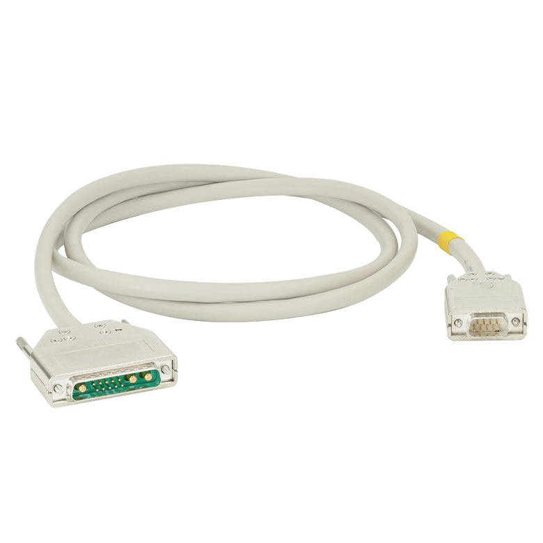 | 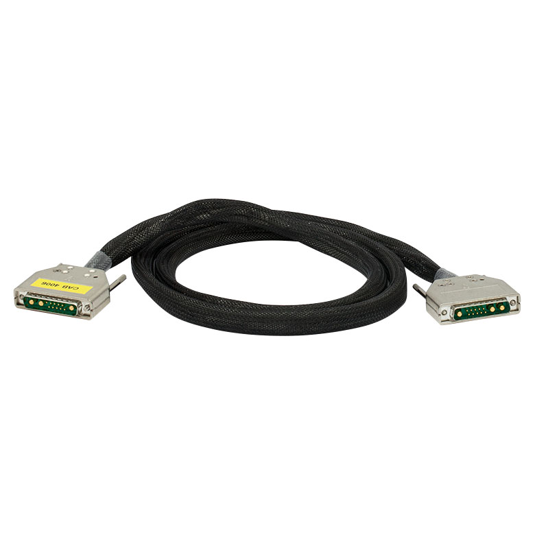 | 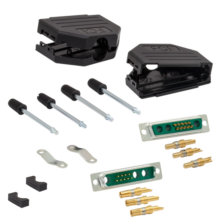 |
| Description | Standard Laser Diode Cable | High Current Laser Diode Cable | 13W3 Male and Female Connector Kit (One Each) |
| Max Current | 5 A | 20 A | 20 A |
| Connector Type | 13W3 Male to DB-9 Male | 13W3 Male to 13W3 Male | Loose 13W3 Connectors, Male and Female |
このケーブルは、 ITC4000シリーズの半導体レーザ駆動電流 & 温度コントローラまたはLDC4000シリーズの電流コントローラと半導体レーザの接続にお使いいただけます。当社では、ご自身でケーブルのカスタマイズを行っていただけるよう、13W3コネクタのみでも販売しています。CAB4005およびCAB4006のピン配列については、「ピン配列」タブをご参照ください。
尚、ITC4001、ITC4002QCL、ITC4005、ITC4005QCLにはCAB4005が1本とコネクターキットCON4005が1つ、ITC4020にはCAB4006が1本とコネクターキットCON4005が1つ、それぞれ付属しています(詳細は「発送リスト」タブをご参照ください)。
| Item # | CAB4000 | CAB4001 | CON4001 |
|---|---|---|---|
| Click Image to Enlarge | 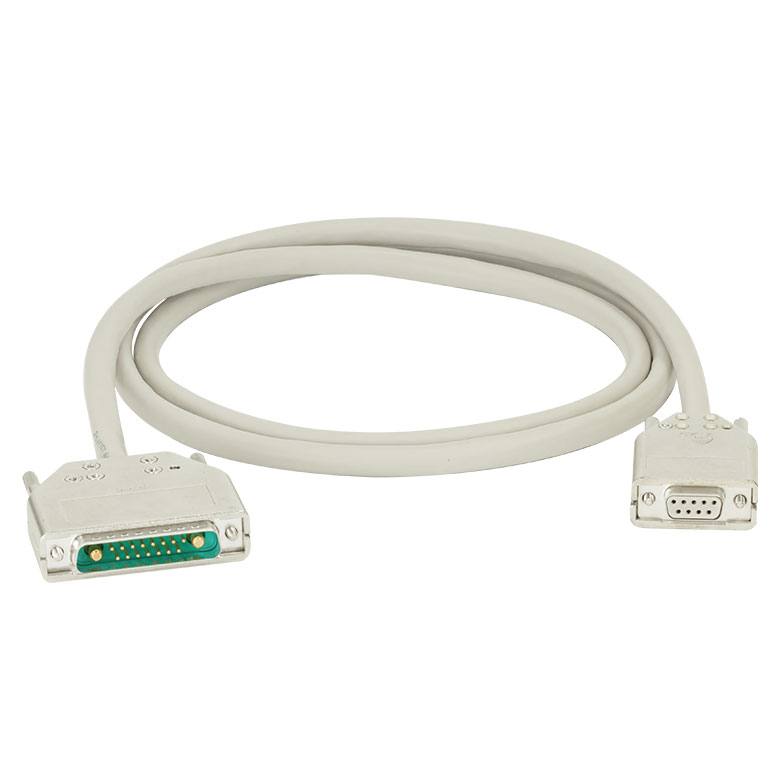 | 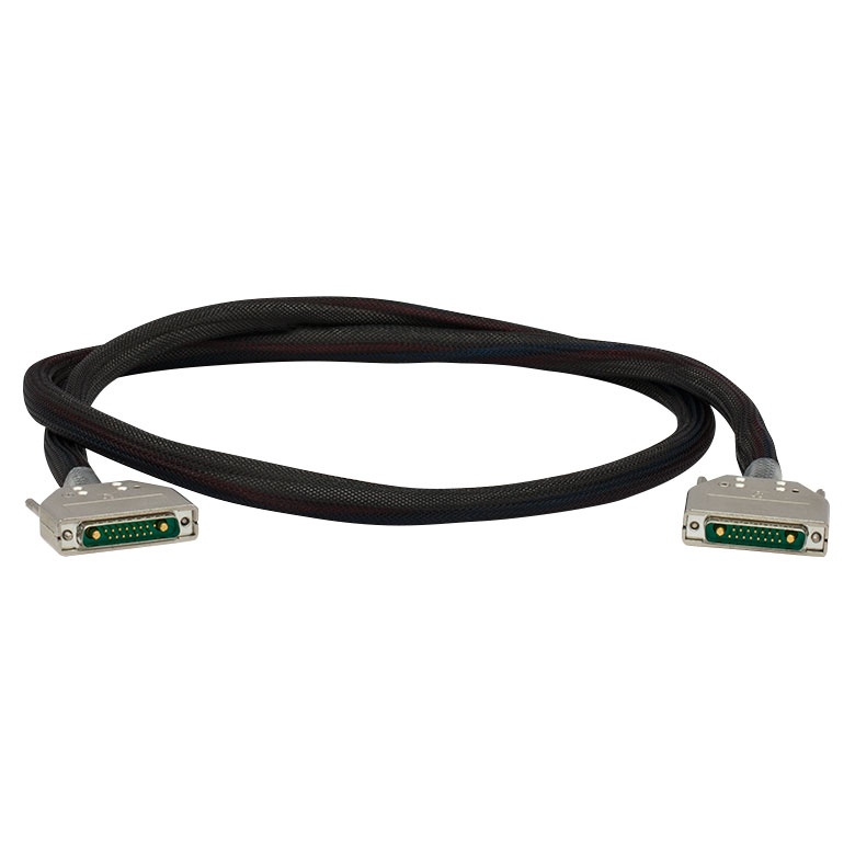 | 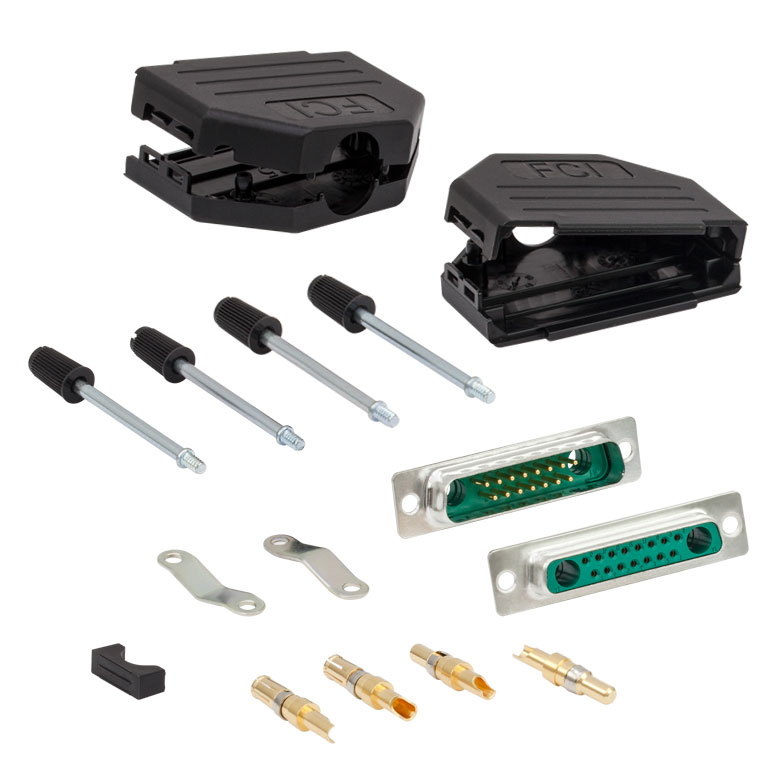 |
| Description | Standard TEC Element Cable | High Current TEC Element Cable | 17W2 Male and Female Connector Kit (One Each) |
| Max Current | 5 A | 20 A | 20 A |
| Connector Type | 17W2 Male to DB-9 Female | 17W2 Male to 17W2 Male | Loose 17W2 Connectors, Male and Female |
このケーブルは、 ITC4000シリーズの半導体レーザ駆動電流 & 温度コントローラまたは温度コントローラTED4015とTEC素子の接続にお使いいただけます。当社では、ご自身でケーブルのカスタマイズを行っていただけるよう、17W2コネクタのみでも販売しています。CAB4000およびCAB4001のピン配列については、「ピン配列」タブをご参照ください。
尚、ITC4001、ITC4002QCL、ITC4005、ITC4005QCLにはCAB4000が1本とコネクターキットCON4001が1つ、ITC4020にはCAB4001が1本とコネクターキットCON4001が1つ、それぞれ付属しています(詳細は「発送リスト」タブをご参照ください)。
| Item # | CAB4007A | CAB4007B | |
|---|---|---|---|
| Click Image to Enlarge | 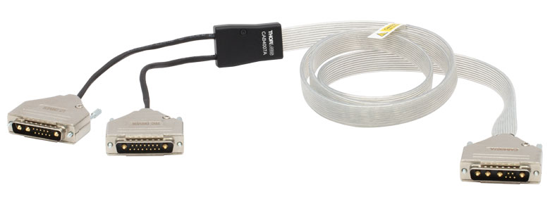 | 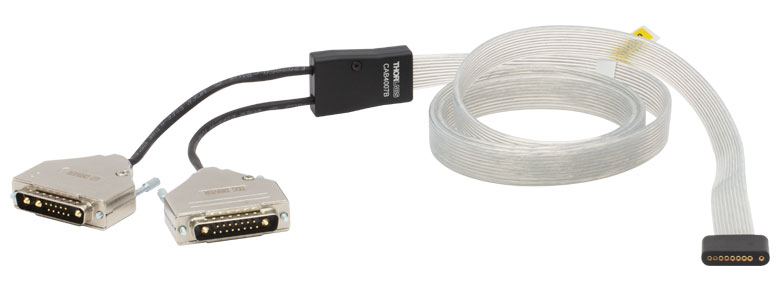 | |
| Description | Hi-Flex LD / TEC Cable for LCM100(/M) Mount | Hi-Flex LD / TEC Cable for 10-Pin HHL Packages | |
| Max Currenta | Pin A1, A2, A3, A4 | 11 A | 10 A |
| Pin 1, 2, 3, 4, 5 | 5 A | 5 A | |
| Connector Type | 17W2 Male and 13W3 Male to 9W4 Male | 17W2 Male and 13W3 Male to a Flat 10-Pin HHL Female Connector | |
| Length | 1.5 m | 1.5 m | |
HHLレーザーパッケージ用コネクターケーブルCAB4007xは、Hi-Flex™†アンシールドケーブルで、一般的なケーブルの許容電流を超える半導体レーザ/TEC用の高電流の用途向けです。
ケーブルCAB4007Aは、9W4コネクタでマウントLCM100/MをITC400xQCLシリーズコントローラに接続します。ケーブルCAB4007Bは、フラット10ピンメス型コネクタであらゆる10ピンHHLレーザを直接ITC400xQCLシリーズコントローラに接続します。 コネクターケーブルCAB4007Bは、LCM100/Mの上部冷却プレートが使用されているときのみご使用いただけます。ケーブルCAB4007A ならびにCAB4007Bのピン配列については「 ピン配列」のタブをご覧ください。
コネクターケーブルCAB4007AまたはCAB4007BをITC400xQCLシリーズコントローラ以外のコントローラに使用するときには、コントローラの仕様に注意し、安全にご使用ください。
†Hi-Flex™はCicoil社の登録商標です。
| Calibration Service Item # | Compatible Controllers |
|---|---|
| CAL-ITC4 | ITC4001, ITC4002QCL, ITC4005, ITC4005QCL, ITC4020 |
Thorlabs offers recalibration services for our ITC4000 Series Combined Laser Diode and TEC Controllers. To ensure accurate measurements, we recommend recalibrating the devices every 24 months. The table to the right lists the controllers for which the CAL-ITC4 recalibration service is available.
Requesting a Calibration
Thorlabs provides two options for requesting a calibration:
- Complete the Returns Material Authorization (RMA) form. When completing the RMA form, please enter your name, contact information, the Part #, and the Serial # of the item being returned for calibration; in the Reason for Return field, select "I would like an item to be calibrated." All other fields are optional. Once the form has been submitted, a member of our RMA team will reach out to provide an RMA Number, return instructions, and to verify billing and payment information.
- Enter the Part # and Serial # of the item that requires recalbration below and then Add to Cart. A member of our RMA team will reach out to coordinate return of the item for calibration. Should you have other items in your cart, note that the calibration request will be split off from your order for RMA processing.
Please Note: To ensure your item being returned for calibration is routed appropriately once it arrives at our facility, please do not ship it prior to being provided an RMA Number and return instructions by a member of our team.