 Products Home / 半導体レーザ用電流コントローラ(LDドライバ)、温度コントローラ、LDマウント / 光デバイスマウント / TO-Can型半導体レーザ(LD)用マウント / TO-Can型半導体レーザー用温度制御付きマウント
TO-Can型半導体レーザー用温度制御付きマウント
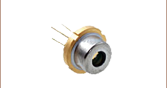
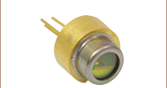
- Mounts for Ø3.8 mm, Ø5.6 mm, and Ø9.0 mm TO-Can Laser Diodes
- Flexure Adapter for Translation of Collimating Aspheric Lens
- Compatible with SM1 Lens Tubes and 30 mm and 60 mm Cage Systems
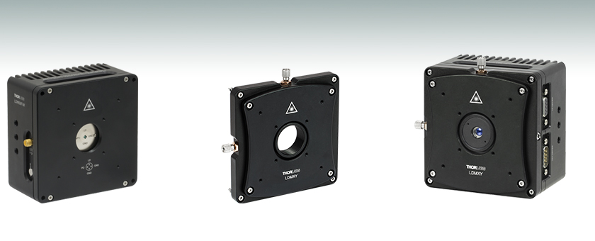
LDM56
Ø5.6 mm Laser Diode Mount
LDMXY
Flexure Adapter for
Collimating Optic
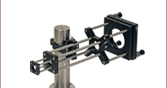
Application Idea
Mount with Laser Diode, LDMXY Flexure Adapter,
and Collimating Lens in Aspheric Lens Adapter
(Each Sold Separately)


Please Wait
Click to Enlarge
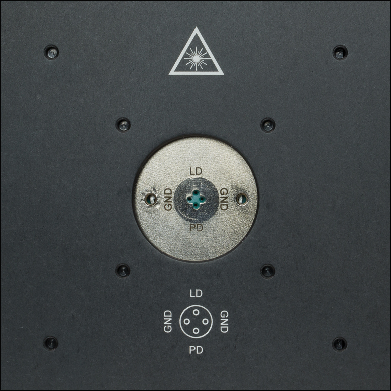
Figure 1.2 LDM56(/M)およびLDM90(/M)のソケットには、ケージロッド取付け用のタップ穴と、SM1ネジ穴が付いています。
(LDM56F(/M)のソケットはこちら)

Click to Enlarge
Figure 1.1 LDM38(/M)のソケットには、ケージロッド取付け用のタップ穴と、SM1ネジ穴が付いています。
| Table 1.3 Supported Laser Diodes | ||
|---|---|---|
| Item # | TO Can Size | Pin Code |
| LDM38(/M) | Ø3.8 mm | G |
| LDM56(/M) | Ø5.6 mma | A, B, C, D, E, Gb, and H |
| LDM56F(/M) | Ø5.6 mma | F and G |
| LDM90(/M) | Ø9.0 mm | A, B, C, D, E, Gb, and H |

Figure 1.4 ピンコード(サポートされているピンスタイルについてはTable 1.3をご覧ください。)
特長
- 半導体レーザの温度制御用TEC素子内蔵
- Ø3.8 mm、Ø5.6 mm、Ø9.0 mmのTO-Can型半導体レーザに対応(Table 1.3をご覧ください)
- 内蔵バイアスTアダプタによって、最大600 MHzまでのレーザ電流のRF変調が可能
- 内蔵のTECロックアウト回路により、半導体レーザを保護(本機能は無効設定も可能)
- 加熱/冷却電力:8 W
- コリメート用光学素子のアライメント用フレクシャーアダプタ(別売り)をご用意
- 30 mmと60 mmケージシステムに対応
- SM1レンズチューブシステムに対応
- ポスト取付け用M6タップ穴
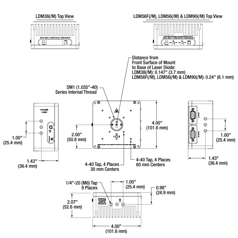
当社のTEC(熱電冷却)内蔵型のLDMシリーズ半導体レーザーマウントは、Ø3.8 mm、Ø5.6 mm、Ø9.0 mmのTO-Can型パッケージの一般的な半導体レーザの温度制御に適しています。半導体レーザはピン配置の通りソケットに差し込み、取付けフランジを2つのネジ(2.0 mm六角レンチ)で締めれば、簡単かつ素早く取り付けられます。取付けフランジにはピンセット用のスロットが付いており、取り付けと取り外しが簡単です。ソケットは、冷却板の前面近傍にあり、リードの短いデバイスも簡単に接続できます。当社ではピグテール付きTO-Can型半導体レーザ用TECマウントもご用意しております。
各マウントの底面と側面には深さ6.4 mmのM6取付け穴が9個あります。また、前面には、当社の30 mmおよび60 mmケージシステム用のケージロッド取付け穴があります。中央にはSM1ネジがあり、SM1レンズチューブも取り付け可能です。半導体レーザ用ソケットは筐体の中心、かつ、ポスト取付け用タップ穴から50.8 mm上の位置にあります。
注)こちらのLDMシリーズは、ピグテール付きTO-Can型半導体レーザに対して温度制御が十分に機能しない可能性があり、また個体によっては装着ができない場合がございますのでご注意ください。ピグテール付き半導体レーザには、専用に設計されたTEC付きLDマウントLDM9LPのご利用をお勧めしております。
変調ならびに温度制御
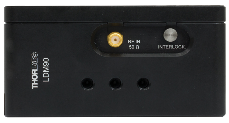
各マウントにはバイアスTが組み込まれており、側面にあるSMAコネクタを使用して100 kHz~最大500 MHz(型番 LDM38/M)または最大600 MHz(型番 LDM56/M、LDM56F/M、LDM90/M)までのレーザのRF変調が可能です。RF変調パワーは最大で200 mWとなっています。ユーザ保護機能として、マウント上部にはレーザEnableを示すLED、側面にリモートインターロックコネクタがあります。
内蔵の熱電冷却器が半導体レーザの温度制御を行います。取付けフランジにより半導体レーザが気流から保護されることで、約10 mKの温度安定性が得られます。レーザ保護機能として、カスタムの接地構成や、TECコントローラが運転停止中にレーザを駆動しないようにするTECロックアウト回路(当社の14ピンバタフライ型半導体レーザーマウントにも装備)があります。TECロックアウト機能は、当社の半導体レーザーコントローラおよび温度コントローラでのみ有効で、必要がない場合は無効にすることができます。
コリメート光学素子のアライメント用フレクシャーアダプタ
LDMシリーズのマウントのフレクシャーアダプタLDMXYにより、コリメート用光学素子をXY方向に±1.0 mm移動できます。移動式光学セルはSM1ネジ付きで当社の非球面レンズアダプタや非球面レンズが取り付けられます。コリメート用光学素子の選択については「LD出力用のコリメート」タブをご覧ください。前面のスリッププレート自体もSM1ネジ付きの光学セルとは独立にXY方向に±1.0 mm粗移動します。スリッププレートには30 mmおよび60 mmケージシステムに対応したケージロッド用ネジ穴があります。そのため、スリッププレートに取り付けたケージシステムの荷重は、フレクシャ機構部分から隔離されます。スリッププレートは4個の標準的なキャップスクリュを緩めて調整します。アダプタLDMXYをLDMシリーズのマウントに取り付ける際にも4個の固定ネジを使用します。すべてのネジは2.0 mm六角ボールドライバや六角レンチが使用可能です。
半導体レーザ用マウント向けの推奨電流コントローラならびに温度コントローラ
こちらのマウントは当社のLDCシリーズ半導体レーザーコントローラならびにITCシリーズ半導体レーザ/TECコントローラのすべてに対応します。一体型の半導体レーザ/TECコントローラを使用して温度制御する場合以外には、当社の温度コントローラをお勧めします。当社の各コントローラにはDB9コネクタに適したケーブルが付属しているため、コントローラを不適切に接続することはありません。またこれらのコントローラには保護回路が内蔵されていて不使用時のレーザを保護します。詳細については、「電子制御」タブをご覧ください。

Click to Enlarge
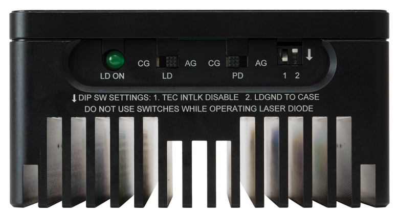
Figure 1.6 筐体上面:ピン配置設定スイッチ
(写真はLDM56F(/M)、LDM56(/M)およびLDM90(/M)の上面。
詳細については「ピン配置」タブをご覧ください。
LDM38(/M)の上面の写真はこちらをクリックしてご覧いただけます。)
| Item # | LDM38(/M) | LDM56(/M) | LDM56F(/M) | LDM90(/M) | |
|---|---|---|---|---|---|
| Laser Diode | |||||
| Supported Laser Diode Package | Ø3.8 mm | Ø5.6 mma | Ø9.0 mm | ||
| Supported Pin Configuration(s) | G | A, B, C, D, E, Gb, and H (Switch Selectable) | F and G (Switch Selectable) | A, B, C, D, E, Ga, and H (Switch Selectable) | |
| Accepted Pin Lead Diameter | 0.008" - 0.016" (0.2 - 0.41 mm) | 0.015" - 0.020" (0.38 mm - 0.51 mm) | |||
| Accepted Pin Lead Length | 0.177" - 0.250" (4.50 mm - 6.35 mm) | 0.26" - 0.40" (6.5 - 10.1 mm) | 0.30" - 0.60" (7.5 - 15.2 mm) | ||
| Pin Hole Array Diameter | 0.06" (1.4 mm) | 0.08" (2.0 mm)a | 0.10" (2.5 mm) | ||
| Laser Diode Depthc | 0.147" (3.7 mm) | 0.24" (6.1 mm) | |||
| Laser Current (Max, Tambient = 25 ºC) | 1 A | 2 A | |||
| RF Modulation Frequency (Bias-T) | 100 kHz to 500 MHz | 100 kHz to 600 MHz | |||
| RF Input Impedance | 50 Ω | ||||
| RF Max Power | - | 200 mW | |||
| Temperature Controller | |||||
| TEC Current (Max) | 5.6 A | 5 A | |||
| TEC Voltage (Max) | 3.6 V | 4 V | |||
| TEC Heating/Cooling Capacity (Tambient = 25 ºC) | 8 W | ||||
| Typical Temperature Range (LD Dependent) | - | 0 to 70 °C | |||
| Temperature Sensors | Thermistor | 10 kΩ ± 2.2% @ 25 °C, NTC, β = 3984 K | 10 kΩ ± 3% @ 25 °C, NTC, β = 3977 K ± 0.75% | ||
| Thermocouple | AD592AN (1 μA/°K) | ||||
| Common Specifications | |||||
|---|---|---|---|---|---|
| Laser Interface | DB9 Female | ||||
| TEC Interface | DB9 Male | ||||
| RF Modulation Connector | SMA | ||||
| Interlock Connector | 2.5 mm Phono Jack | ||||
| Indicator | Green LED - LD Enabled | ||||
| Mounting Holes | Imperial Mounts | 1/4"-20 (9 Places) | |||
| Metric Mounts | M6 x 1.0 (9 Places) | ||||
| Cage Compatibility | 4-40 Taps (8 Places) for 30 mm and 60 mm Cage Systems | ||||
| Operating Temperature | 10 to 40 °C | ||||
| Storage Temperature | 10 to 80 °C | ||||
| Dimensions (L x W x D) | 4.00" x 4.00" x 2.07" (101.6 mm × 101.6 mm × 52.6 mm) | ||||
| Weight | 1.9 lbs (0.87 kg) | ||||
Click for Details
Figure 2.1 取付け穴の配置図
LDドライバ: D型 メス
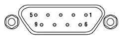
| Pin | Signal | Description (Item #s LDM38(/M), LDM56(/M), and LDM90(/M)) | Description (Item # LDM56F(/M)) |
|---|---|---|---|
| 1 | Interlock and Status Pin (LDC Specific) | Laser Diode (LD) Status Indicator and Interlock Circuits input. | |
| 2 | Photodiode Cathode | This pin is connected to the 9 o'clock pin on the laser socket when the photodiode (PD) polarity switch is set to anode ground (AG). It is attached to ground and the 12 o'clock and 6 o'clock pins on the laser socket when the PD polarity switch is set to cathode ground (CG). | This pin is connected to the 6 o'clock pin on the laser socket when the photodiode (PD) polarity switch is set to anode ground (AG). It is attached to ground and the 12 o'clock and 3 o'clock pins on the laser socket when the PD polarity switch is set to cathode ground (CG). |
| 3 | Laser Ground (Case) | This pin is connected to the 3 o'clock and 9 o'clock pins on the laser socket and corresponds to the settings of the LD and PD polarity switches (i.e. If the LD and PD switches are set to AG then this pin grounds the anodes of the laser and photodiodes). | This pin is connected to the 12 o'clock and 3 o'clock pins on the laser socket and corresponds to the settings of the LD and PD polarity switches (i.e. If the LD and PD switches are set to AG then this pin grounds the anodes of the laser and photodiodes). |
| 4 | Photodiode Anode | This pin is connected to the 6 o'clock pin on the laser socket when the PD polarity switch is set to CG. It is attached to ground and the 3 o'clock and 9 o'clock pins on the laser socket when the PD polarity switch is set to AG. | This pin is connected to the 6 o'clock pin on the laser socket when the photodiode (PD) polarity switch is set to cathode ground (CG). It is attached to ground and the 12 o'clock and 3 o'clock pins on the laser socket when the PD polarity switch is set to anode ground (AG). |
| 5 | Interlock and Status Return | Status and interlock circuitry return. | |
| 6 | Laser Diode Voltage (Cathode) | This pin is connected to LD interface pin 7, through a 499 Ω resistor, when the LD polarity switch is set to AG. It is attached directly to LD interface pin 3 when the LD polarity switch is set to CG. | |
| 7 | Laser Diode Cathode | This pin is connected to the 12 o'clock pin on the laser socket when the LD polarity switch is set to AG, and it floats otherwise. | This pin is connected to the 9 o'clock pin on the laser socket when the LD polarity switch is set to AG, and it floats otherwise. |
| 8 | Laser Diode Anode | This pin is connected to the 12 o'clock pin on the laser socket when the LD polarity switch is set to CG, and it floats otherwise. | This pin is connected to the 9 o'clock pin on the laser socket when the LD polarity switch is set to CG, and it floats otherwise. |
| 9 | Laser Diode Voltage (Anode) | This pin is connected to LD interface pin 8, through a 499 Ω resistor, when the LD polarity switch is set to CG. It is attached directly to LD interface pin 3 when the LD polarity switch is set to AG. | |
TECコントローラ: D型、オス
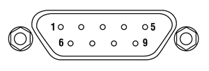
| Pin | Signal | Description |
|---|---|---|
| 1 | TEC Lockout (+) | This pin is connected to the anode of the photo-relay side of the TEC Lockout circuit. When using Thorlabs TEDs no external circuitry is required. To use these features with third-party controllers please refer to the Status and Interlock section of the mount's manual. |
| 2 | +Thermistor | The 10 kΩ at 25 °C NTC thermistor (provided for temperature feedback). |
| 3 | -Thermistor | The thermistor return pin. |
| 4 | +TEC | This pin is connected to the positive terminal of the TEC element. |
| 5 | -TEC and TEC Lockout (-) | This pin is connected to the negative terminal of the TEC element, and also is common to the cathode of the photo-relay of the TEC Lockout circuit - refer to the Status and Interlock section of the mount's manual. |
| 6 | N.C. | Not Used. |
| 7 | AD592(-) | The negative terminal of the AD592 temperature transducer. When using Thorlabs TEDs no external circuitry is required. To use this device with third party controllers it must be properly biased. Refer to Analog Devices AD592 Data for application information. |
| 8 | N.C. | Not Used. |
| 9 | AD592(+) | The positive terminal of the AD592 |
オプションのリモートインターロック
2.5 mm メス型 モノラルジャック
| Specification | Value |
|---|---|
| Type of Mating Connector | 2.5 mm Mono Phono Jack |
| Open Circuit Voltage | +5 VDC with Respect to System Ground (When Used in Conjunction with Thorlabs Drivers) |
| Short Circuit Current | 10 mA DC (Typ.) |
| Connector Polarity | Tip: Positive; Barrel: Ground |
| Interlock Switch Requirements | Must be N.O. dry contacts. Under no circumstances should any external voltages be applied to the Interlock input. |
RFレーザ変調入力*
SMA メス型
*外部電源(最大500 MHz)による変調用RF入力端子。これはバイアスTを介してレーザへ直接AC結合している50 Ω入力です。
Figure 4.1 当社のピン配置
半導体レーザのピン配置
当社ではUV、可視、近赤外域で発光する様々なTO-Can型半導体レーザをご提供しております。多くの半導体レーザーパッケージではモニタ用フォトダイオードを内蔵しています。また、電気接続端子の配置はパッケージの内部配線によって異なります。当社ではこの異なるピン配置をFigure 4.1のようにピンスタイルA~Hに分類しています。ご提供している半導体レーザのピン配置のスタイルは、当社ウェブサイトに掲載している仕様表ならびに半導体レーザとともに発送する仕様書にも記載されています。半導体レーザーパッケージのピンスタイルは、Figure 4.1のピン配列図でご確認いただけます。ピンスタイルの種類、ピン配置、そして下記情報をもとに半導体レーザに正しく電源供給を行ってください。
半導体レーザの設置向きは各マウントの前面に刻印されています。また、Figure 4.2~4.4もご参照ください。
マウントLDM38/Mの互換性
半導体レーザーマウントLDM38/Mは、Gピン配置(Figure 4.1参照)のØ3.8 mm半導体レーザに対応します。マウントLDM38/Mの電子部品の構成と動作の詳細については、LDM38(/M)の取扱説明書をご参照ください。
マウントLDM56/MおよびLDM90/Mの互換性
半導体レーザーマウントLDM56/MおよびLDM90/Mは、それぞれØ5.6 mm、Ø9 mmでピン配置がA、B、Cの3ピン型半導体レーザーパッケージすべてに対応します。このピン配置のパッケージには半導体レーザとモニタ用フォトダイオードが内蔵されており、半導体レーザ(LD)用のピン、フォトダイオード(PD)用のピン、共通の接地ピンがあります。
Figure 4.4 LDM56F(/M)の標準的なピン配置
Figure 4.3 LDM56(/M)およびLDM90(/M)の標準的なピン配置
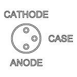
Figure 4.2 DM38(/M)の標準的なピン配置

Click to Enlarge
Figure 4.5 ジャンパJP5を示したマウントLDM90(/M)の内部回路
これらのマウントは、ピンスタイルE、G、Hのモニタ用フォトダイオードが付いていない半導体レーザにも対応します。これらのレーザは3ピン型のパッケージでFigure 4.1のように半導体レーザ用のピンと接地ピンが3ピン中に含まれています。ピンスタイルがGの半導体レーザと使用する場合は、内部ジャンパをFigure 4.5のように設定してください。詳細についてはスタイルGのピン配置セクションをご覧ください。
マウントLDM56/MおよびLDM90/Mは、当社が現在ご提供しているピンスタイル(Figure 4.1参照)の4ピン型半導体レーザすべてにも対応します。ピンスタイルA、B、Cと同様に、スタイルDの半導体レーザーパッケージには半導体レーザとモニタ用フォトダイオードが付いています。ただし、スタイルDのパッケージについてはフォトダイオードはケースに接続していません(フロートの状態です)。
なお、ピンスタイルDとFのパッケージは似ていますが、これらのマウントはピンスタイルFの4ピンパッケージには対応しませんのでご注意ください。ピンスタイルFは、これらのマウント内では使用できないピン配列となっております。ピンスタイルFの配置のØ5.6 mm半導体レーザには、マウントLDM56F/Mをご使用ください。
マウントLDM56/MおよびLDM90/Mの電子部品の構成と動作の詳細については、LDM56(/M)およびLDM90(/M)の取扱説明書をご参照ください。マウントLDM56/MはTO-46型パッケージの半導体レーザとほぼ同形状をしています。詳細については当社までお問い合わせください。
LDM56F/Mの互換性
半導体レーザーマウントLDM56F/Mは、FまたはGピン配置(Figure 4.1参照)のØ5.6 mm半導体レーザに対応します。マウントLDM56F/Mの電子部品の構成と動作の詳細については、LDM56F(/M)の取扱い説明書をご覧ください。マウントLDM56F/MはTO-46型パッケージの半導体レーザとほぼ同形状をしています。詳細については当社までお問い合わせください。
マウントLDM56およびLDM90のスタイルGのピン配置について
ピンスタイルGのパッケージは半導体レーザのみの構成で、フォトダイオードは内蔵されていません。こちらの半導体レーザのタイプは当社のマウントLDM56F/Mに直接取り付けが可能です。マウントLDM56/MまたはLDM90/Mにも取り付け可能ですが、LDピンと接地ピンが対角位置(つまりマウントのLDとPDの位置、または3時と9時の位置)にあるため、内部の配線を若干変更する必要があります。
ピンスタイルGの半導体レーザをLDM56/MまたはLDM90/Mで駆動するためには、マウントのPDピンを接地する必要があります。PDピンを接地するには、まずマウントの前面カバーを外します。ジャンパJP5をマウントの左側に置きます。内部回路の写真はFigure 4.5をご覧ください。ジャンパJP5は赤丸で囲まれています。ジャンパを設定する際には、刻印されているガイドに従ってください。PDピンを接地することにより、LDはLDの刻印(12時)とPDの刻印(6時)の間に接続でき、マウントが半導体レーザのみ(フォトダイオード無し)を駆動可能になります。LDのAnodeを12時するか6時にするかはマニュアルのFigure2をご覧ください。
半導体レーザ電流コントローラ
半導体レーザの電流コントローラは、半導体レーザの仕様と用途を考慮してお選びください。当社では、低出力(低電流、低電圧)から高出力(高電流、高電圧)まで様々な半導体レーザーコントローラをご用意しております。また半導体レーザ駆動電流コントローラと温度コントローラが一体化した製品、またはセットになった製品もいくつかご提供しています。温度コントローラについては下記のTECコントローラのセクションをご覧ください。
当社のLDC2xxCシリーズのコントローラは、多くの半導体レーザに適用できます。LDC200CVは、特にVCSELに適した設計がなされており、扱いが比較的難しいVCSELを安全に動作させることができます。また、LDC201CUは超低ノイズ(<0.2 μA RMS)の電流供給を特長としています。青色または短波長の半導体レーザを駆動するためによく用いられる高電圧用途には、コントローラLDC202C、LDC205CまたはLDC210Cをご検討ください。高出力半導体レーザの駆動用には、それぞれ駆動電流が2 Aまたは4 AのLDC220CおよびLDC240Cをお使いいただけます。高電流対応の製品(5 Aと 20 A)、T-Cubeに接続可能な製品やラックマウント型の製品もあります。これらのコントローラはすべて同じように動作します。こちらではLDC2xxCシリーズのコントローラについてのみご説明いたします。
TECコントローラ
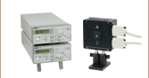
当社ではTECコントローラとして、スタンドアローン型、半導体レーザーコントローラ/温度コントローラ一体型やセットなど、様々な種類および形態でご提供しております。TED200Cのベンチトップ型温度コントローラは、LDMシリーズにマウント済みの半導体レーザの温度管理に適しています。この製品の特長は幅広い動作温度範囲と、12 Wの冷却、そして高い温度安定性です。さらに大きな冷却力と高い温度安定性が必要な場合には、225 Wの温度コントローラTED4015をご使用いただけます。
こちらのマウント内のTEC素子は、ユニット側面のメス型DB9コネクタを介して温度コントローラに接続可能です。他のコネクタータイプに対応した温度コントローラに対しては、アダプターケーブルのご用意があります。当社以外のメーカのコントローラをご使用の場合、取扱説明書に記載されているピン配列や詳細をご参照ください。TECコントローラは手順通りに使用し、マウント内蔵のTEC素子がオーバードライブしないようご注意ください。
RF変調
半導体レーザの変調は可能ですが、半導体レーザーコントローラでは変調はできません。半導体レーザーコントローラからの入力は、低帯域幅のDC電流のみを半導体レーザに通すインダクタを介して送られ ます。半導体レーザの高周波変調を可能にするためには、マウント内蔵のバイパスを使用してローパスフィルタを迂回させる必要があります。バイパスはマウント側面のSMAコネクタからアクセスでき、バイアスTで直接レーザに接続します。50 ΩのRF入力端子は、最大500 MHz(型番LDM38)または600 MHz(型番LDM56、LDM56FおよびLDM90)のAC結合RF源に対応します。
半導体レーザを適切に変調するためには、まず変調電圧を正しく算出しなければなりません。変調電圧VRFは、半導体レーザの変調電流ILDと入力インピーダンスZinputの積で算出します。
ILDはメーカ提供の数値、Zinputはマウントのインピーダンスで、50 Ωです。
変調電圧を設定するときには、数式(1)で求められた数値の1/10程度から開始することをお勧めします。VRFまたはご希望の変調が得られるまで変調電圧をゆっくりと上昇させます。そして半導体レーザーコントローラを使用し、DC電圧を適切なレベルまで増加させます。
注意:RF入力は直接半導体レーザに接続されます。ノイズやスプリアス信号は抑制されません。半導体レーザのオーバードライブを防ぐために安定かつノイズの少ないRF源をご使用ください。また、RF電圧が数式(1)で求められた数値を超えると半導体レーザはすぐオーバードライブとなります。半導体レーザの損傷を防ぐため、RF電圧の制御ならびに調整は慎重に行ってください。
安全保護装置
こちらのマウントは、側面パネルにリモートインターロックコネクタが装備されています。レーザ光源を有効にするには、リモートインターロックコネクタ端子間をショートさせます。この機能によって、遠隔作動スイッチをコネクタに接続させることができるようになります(オープンドア表示など)。この機能を使用できるようにするには、normally openのスイッチを閉じる必要があります。スイッチを開いている状態にすると、半導体レーザは自動的に停止します。
すべてのユニットは、インターロックコネクタをショートした状態で出荷されます。インターロック機能をお使いにならない場合、このままでユニットは正常に動作します。インターロック機能をお使いになりたい場合は、お客様側でご用意いただいたリモートインターロックスイッチに、適合する適切なコネクタを接続する必要があります。その後、ショートデバイスを入力端子から取り外し、このコネクタをインターロック入力端子に取り付けます。
インターロック入力端子には2.5 mmモノラルジャックのみ接続可能です。このコネクタは多くのメーカが取り扱っています。
Video Insights(How-to動画集):TO-Can型半導体レーザのセットアップ
TO-Can型半導体レーザをマウント内に取り付けて、温度と電流の制御下で動作するように設定する際、誤ってレーザに損傷を与えたり破損したりする可能性が多くあります。動画では、人体と半導体レーザを損傷の危険から守る方法を順を追って説明しています。
そのほかにも実験室でお使いいただけるヒント、工夫や方法などの動画がこちらからご覧いただけます。ウェビナーでは、当社製品を実用的かつ理論的にご紹介しています。
半導体レーザに合ったコリメート用レンズと非点隔差補正光学素子の選択
半導体レーザ(LD)の出力は大きく拡散するので、コリメートには光学素子が必要となります。非球面レンズは、球面収差を補正する能力に優れているので、コリメート後のレーザ光線の径を1~5 mmとしたい場合は非球面レンズを用いるのが一般的です。 希望のビームの大きさと透過帯域は、使用するレンズに依存するため、半導体レーザ出力光をコリメートするためには、最適な非球面レンズを選ぶことが不可欠です。 半導体レーザのコリメート光の大きさを計算するに当たって、まず拡散について理解する必要があります。
端面発光半導体レーザの出力にもまた、かなりの非点隔差があります。ビーム発散角は、平行および垂直方向において異なり、楕円ビームをもたらします。 コリメート後にアナモフィックプリズムペアやシリンドリカルレンズを挿入することによって、この楕円率を補正することができます。半導体レーザ出力の拡散は、チップの2軸の「ビーム発散角(FWHM) - 平行」と「ビーム発散角(FWHM) - 垂直」により典型値として規定されています。 半導体レーザは、ロットごとにバラツキがありますが、典型的な発散角を用いることにより、より多くの用途に適合できます。
ここでは目的の用途に合った適切なレンズを選定する上で重要な仕様について簡単な例をあげてご説明します。
例:785 mm、25 mWの半導体レーザL785P25、コリメート後のビーム径:Ø3 mm
ステップ1: レーザ出力光をコリメートする
半導体レーザ L785P25の仕様書によれば、光線の垂直と平行方向における典型的な発散角はそれぞれ30oと8oです。大きい(垂直の)ビーム発散角はFigure 66Aに示されています。小さい(平行の)ビーム発散角はFigure 66Bに示されています。 2軸のこの非点隔差または非対称性により、光が発散するにつれて、光線は楕円形になっていきます。 コリメートの段階でできるだけ多くの光を集光するためにどの計算においても2つの発散角のうち、大きな方の数値を使ってください(この場合は30o)。
注: 平行と垂直表記は、半導体レーザの接合面に対して規定されます。
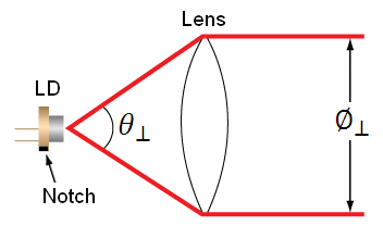
Figure 66A L785P25からの垂直方向のビーム発散角、スタイルBのLD
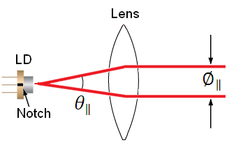
Figure 66B L785P25からの平行方向のビーム発散角、スタイルBのLD
Figure 66Aと66Bでは、LDは半導体レーザ、 と
と  は、それぞれ平行および垂直方向のビーム径、
  と
と は、それぞれ平行および垂直方向の発散角を表します。 Figure 66Aと66Bの中の切り込み(Notch)は、パッケージ内部の半導体レーザの方向を決定するために利用できます。半導体レーザは通常、切り込み(Notch)に対し平行方向に設置されます。しかし、特に異なる半導体パッケージについては、多くの例外があります。 半導体レーザとその発光方向には、十分にご注意ください。
Ø3 mmのコリメート後のビーム径を得るために必要なレンズの焦点距離を計算する上で、下記の計算式を使用できます。
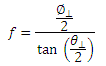
 は焦点距離で 、目的とする垂直方向のビーム径 をもたらすLDとレンズ間の距離です。 30oの発散ビームをØ3 mmのコリメート光にコリメートするために、必要なレンズの焦点距離は、 = 5.6 mmです。
計算式では、目的とする(垂直方向の)主軸径を得るための焦点距離を計算します。 次に、式から得られた焦点距離に最も近い焦点距離の非球面レンズを選定します。 ここで、レンズの直径は、目的とする主要軸のビーム径よりも大きくなければならないことにご注意ください。
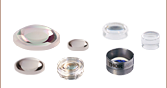
当社では数多くの種類の非球面レンズをご用意しています。 この使用例における理想的なレンズは、-B ARコーテイングの施されたモールドレンズで焦点距離が約5.6 mmのものとなります。C171TMD-B (マウント付き)または354171-B (マウント無し)の非球面レンズの焦点距離は6.20 mmです。次に半導体レーザの開口数(NA)がレンズのNAより小さいことを確認してください。これは半導体レーザの放出する光がレンズに蹴られることを防ぐためです。
0.30 = NALens > NADiode ~ sin(15) = 0.26
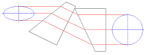
Figure 66C 楕円形から円形のビームに変換するための、アナモフィックプリズムペアと光線追跡図
実際の焦点距離と主要軸の発散角を使って上記の式を解くことにより、実際の主要軸のビーム径が得られます。
ステップ2:非点隔差を補正する
Figure 66Aと66Bに示されている通り、端面発光半導体レーザからの発光には非点隔差があります(2つの異なる軸に対して非対称です)。 これを補正し円形ビームにするには、コリメート後にアナモフィックプリズムペアやシリンドリカルレンズを使って、短軸径を拡大することが必要です。 Figure 66Cは、目的とする対称ビームを得るために、短軸の楕円ビームを拡大しているアナモフィックプリズムペアを示しています。
![]() = 6.20 mm = 8oを使って式を解きます。この結果、短軸径 = 0.9 mmが得られます。 と を比較すると、短軸ビームを3.5倍率拡大する必要があることが分かります。この3.5倍拡大は、マウント付きアナモフィックプリズムペアPS881-Bを使って行うことができます。
= 6.20 mm = 8oを使って式を解きます。この結果、短軸径 = 0.9 mmが得られます。 と を比較すると、短軸ビームを3.5倍率拡大する必要があることが分かります。この3.5倍拡大は、マウント付きアナモフィックプリズムペアPS881-Bを使って行うことができます。
レンズチューブの取付け
マウント付き非球面レンズには、当社のアダプタSM05TxxまたはS1TMxxをご使用いただけます。レンズが半導体レーザに接触しないようご注意ください。アダプタSM05TxxはSM1-SM05変換アダプタSM1A6Tをお使いいただく必要があります。
マウント無しの非球面レンズは、アダプタLMRAxxにエポキシ樹脂で接着することができ、その後SM1-SM05変換アダプタSM1A6T に取付けることができます。 アダプタのSM1ネジ切り部は、レンズ/マウント/アダプタのアセンブリを半導体レーザーマウントの前面プレートに装着するのに利用できます。 アダプタSM1A6Tには10 mmの取付け部があるため、当社の非球面レンズのほぼすべてにお使いいただけます。
上の例では、マウント付きレンズC171TMD-BにM8 x 0.5 のネジ切りが付いているので、ネジ付きアダプタS05TM08が必要となります。M8-SM05変換アダプタS05TM08は、SM1-SM05 変換アダプタSM1A6T を使って、半導体レーザーマウントに取り付けることができます。 アダプタS05TM08とSM1A6Tの両方を調整することで、半導体レーザとレンズの間の距離を補正することができます。
マウント無しの非球面レンズ354171-Bをご使用の場合は、最初にアダプタLMRA5に接着する必要があります。 その後、SM1-SM05アダプタSM1A6T に取り付けることができます。 ここでも、非球面レンズの調整はアダプタLMRA8とSM1A6Tで行うことができます。
ケージシステムへの取付け
焦点距離が8 mm以上のマウント付きまたはマウント無しの非球面レンズは、当社の30 mmケージシステムを用いてケージに取り付けることができます。 ケージロッドは、半導体レーザーマウントの前面プレートに直接取り付けることができます。ケージプレートCP33/Mを用いると、マウント付き非球面レンズが取付けられたアダプタS1TMxxを保持したり、マウント無し非球面レンズが接着されたアダプタLMRAxxをアダプタSM1A6Tに取付けて保持したりすることができます。
より長距離の移動調整には、移動量13 mmの移動ステージCT1A/Mをご使用いただけます。 CT1A/Mには直線移動距離13 mm、最小目盛10 µm(0.001インチ)のマイクロメータが付いています。キャリッジの最小移動量は約1 µmです。
アナモフィックプリズムペアの取付け
半導体レーザからの出力ビームの非点隔差は、アナモフィックプリズムまたはシリンドリカルレンズのいずれかを使って補正できます。 上記の例で選定されたように、円形ビームプロファイルを生成するには、3.5倍率のマウント付きアナモフィックプリズムペア(PS881-B)が必要になります。 マウント無しのプリズムを使用することも可能です。
マウント付きアナモフィックプリズムペアPS881-Bは、出光端にSM05ネジ切り加工ほどこされているか、あるいはSM1レンズチューブ内部に取り付けられています。 アナモフィックプリズムペアの入力光および出力光は互いに相殺し合うため、プリズムは別のケージまたはレンズチューブの光軸に取り付ける必要があります。
| Posted Comments: | |
Mitchell Harrah
(posted 2024-04-05 17:03:30.49) Is there a ThorLabs mount that can handle a 5A laser current (as seen in the L1480G1)? ksosnowski
(posted 2024-04-26 09:22:49.0) Hello Michael, thanks for reaching out to Thorlabs. Our LDM90 and LDM56 series mounts on this page handle 2A max, and unfortunately we do not have a TO9 mount for higher currents like the max operating point of L1480G1. For some other laser package styles we have designed higher power mounts like LDMC20, which ultimately incorporate additional cooling via vibrationally isolated blower fan. I have reached out directly to discuss your application in further detail. Robert Lanner
(posted 2023-06-07 13:15:48.193) Hi, I 'm interested in locking the setscrews on LDMXY. Is that possible? Thanks, Robert ksosnowski
(posted 2023-06-07 11:35:39.0) Hello Robert, thanks for reaching out to Thorlabs. To help keep a low profile on the LDMXY adjuster plate, we used smaller adjusters without a locking nut. It is unfortunately not feasible to add a locking nut here in current design as the bushing is recessed slightly, meaning the locking nut would need to conform to the LDMXY housing feature to make contact while not interfering with the travel. Hans Osthoff
(posted 2022-03-02 13:04:33.99) Re: https://www.thorlabs.com/newgrouppage9.cfm?objectgroup_id=308
Application Idea
Mount with Laser Diode, LDMXY Flexure Adapter,
and Collimating Lens in Aspheric Lens Adapter
(Each Sold Separately)
Excellent idea to show application ideas - would be more useful if the part # for the mount, flexure adapter, collimating lense, and lens adapter were stated as well (Ikea does this for showcase rooms) ksosnowski
(posted 2022-03-03 10:36:32.0) Thanks for reaching out to us, Hans. This page showcases the mount itself, for a more application-centric showcase you can check out our Complete Laser Diode (LD) Operation Starter Sets which have a kit breakdown including a lens, mounts, and controller, for a user-picked diode. If you need assistance choosing a setup or checking compatibility, you can email techsupport@thorlabs.com, call, or chat in, and we are happy to help. Paul Lebow
(posted 2021-12-13 17:24:24.553) L785P25 ellipticity correction-
In your example you only give the lens choice for one axis of divergence. What is the choice for the cylindrical lens to collimate in along the other axis? Can you provide the appropriate lens pairs for a chosen LD?
Thanks
Paul Lebow YLohia
(posted 2021-12-14 01:26:46.0) Hello Paul, the choice of lens depends on the exact target beam diameter as well as the exact divergence angle of your particular L785P25 (due to piece-to-piece variations). You may use the equation for the focal length listed on the "LD Collimation" tab to select the appropriate focal length for each axis of the beam, once your beam diameter and divergence parameters are known. Our cylindrical lenses can be found here: https://www.thorlabs.com/navigation.cfm?guide_id=14 Yu-Pu LIN
(posted 2021-05-26 09:53:19.03) Dear Sirs,
We have purchased a LDM90/M to control your 1370nm d9 TO can laser diode (L1370G1). We want to use a third-party controller to drive the laser. The TEC part works very well. However, I haven't succeed to drive the laser correctly by following your manual (set the jumper for style G, set the correct ground for LD and PD). I'm stucked at which pin should I connect to my current source to drive the laser.
Could you help me with this problem ?
Thank you in advance.
Best regards,
Yu-Pu LIN cdolbashian
(posted 2021-09-10 10:55:29.0) Thank you for contacting us at Thorlabs! I have contacted you directly, and we discovered that you inversed the polarity of the LD socket via incorrect mount configuration. Selecting the correct configuration corrected your problem without further issue. Yunzheng Wang
(posted 2021-04-14 17:59:47.05) Hi, I buy a LDM56/M last week. When I send a 10us pulse into the RF port, the output waveform is very bad and not a pulse. I also have a LM9LP laser mount. its output is very well. I open the covers of these two and find their difference that LM9LP has a Marki Bias Tee but LDM56/M has only a capacitor. So I think maybe this is the reason. Please help me to solve this problem. I want to get a good pulse waveform when I input a pulse RF signal. Thank you. YLohia
(posted 2021-04-15 11:57:22.0) Hello, thank you for contacting Thorlabs. This effect stems from the fact that there is a low frequency block (Bias-T) on the LDM56 (we spec >100 kHz bandwidth), which will have an impact on the DC/low frequency components of your input waveform. It is recommended to directly modulate the LD at lower frequencies as performance will be inconsistent below 100 kHz. Ronan Le Harzic
(posted 2019-06-06 14:04:53.977) Dear,
I work with TO can 5,6 and 9,0 mm laser diodes, I am quite interested in the high power Temperature Controlled Mounts. I would like to use only one LMD for both 5,6 and 9,0 mm laser diodes and not purchase 2, a LMD56 and a LMD90. Why the LMD90 is not compatible for 5,6 mm and 9,0 mm TO can diodes? or is it compatible and I can switch my different laser diodes as I want ?
Brest Regards
Ronan asundararaj
(posted 2019-06-06 08:06:07.0) Thank you for Feedback, Ronan. The LDM90 is not compatible with the 5.6 mm TO can laser diodes. Using a 5.6 mm TO Can in a mount designed for a 9.0 mm laser diode has bad thermal coupling and compromises the lifetime of the diode. user
(posted 2018-02-28 11:15:36.52) Hello, I just purchased the LDM38/M and TLD001. And want to confirm if these two observations are true:
1) The anode and cathode engravings on the LDM38/M are reversed.
2) On the LDM38/M, DIP SW Setting 1. TEC INTLK DISABLE should be set to the "ON" position to enable diode operation. tfrisch
(posted 2018-02-28 04:18:13.0) Hello, thank you for contacting Thorlabs. The engravings are indeed reversed for units sold prior to 2/28/2018, but as the diodes can only be inserted in one direction, they still function properly. Units sold after that date will have correct engravings. As for the TEC Interlock Disable, switching it to ON will indeed bypass the interlock and suppress the interlock error. This will allow normal operation when you do not have a TEC driver compatible with the interlock feature. Please feel free to email us at TechSupport@Thorlabs.com if you need further clarification on either of these. agreen13
(posted 2018-01-09 09:32:24.807) This product is a disappointment after successfully using the TCLDM9 for years. I was hoping to purchase the TCLDM9. The modularity of TCLDM9 was particularly attractive as we often interchange 5.6 and 9 mm diodes. In addition to lacking the modularity of the TCLDM9, the LDM56 is deficient for my needs in that the travel on the threaded hole for mounting collimation optics is only half the length as that in the TCLDM9 which makes mounting our typical optics with out typical diodes (both purchased from Thorlabs) impossible without machining our own parts or purchasing additional parts from Thorlabs. In addition to these design flaws, there is evidence that these products were manufactured with less care than I have come to expect from Thorlabs. Not only was our product shipped with improper engraving, it is evident that the threaded hole for mounting collimation optics and the center of the diode socket are not exactly coaxial. I see that the problem of this offset and the lack of travel on the threads could both be solved with the purchase of an LDMXY but note that such a device has never been required in my work with several iterations of the TCLDM9. Noting the high cost of the LDMXY and the what seems to be the superior design and manufacturing quality of the older model, this seems like a bit of a racket. If the design and manufacturing of the LDM56 is not noted to be improved I will be turning to Newport to fill my lab's future need for products like this. tfrisch
(posted 2018-01-10 11:31:15.0) Hello, thank you for your honest feedback on this new product line. I apologize for the inconvenience this new product line has caused you. The main reason for splitting these laser diode mounts was to improve thermal contact of the 5.6mm laser diodes. The TCLDM9 was designed with a socket that matched the pin spacing for 9mm laser diodes. 5.6mm laser diodes have a smaller pin spacing and outer diameter. The pins of the 5.6mm diode could be bent out to match the hole spacing of the 9mm diode socket, but the cutout of the mount cold plate that allowed the pins to pass through was too large for the 5.6mm diode to make good thermal contact; with as little as 0.25 mm overlap of the flange on the cold block surface. In the newer models, thermal contact is improved with the minimum amount of overlap increased to >1.1 mm. In changing the whole line, our design team also saw the opportunity to make the front plate thinner to allow easier access to the diode in applications that do not use the threaded hole. As you have found, the trade-off for that has been thread depth. I will reach out to you directly about what lenses you are using so we can provide an appropriate adapter. As for the engraving, we apologize for the error, and our design team is correcting their prints to avoid foolish mistakes like this in the future. For the centration, we noticed even with TCLDM9 that the emitting point would translate laterally depending on the mounted diode. Because of this, the face plate was held on with 4 cap screws, but the counterbores were toleranced to be large so that with the screws loosened but under tension, coarse adjustments could be made to the lateral position of the face plate with respect to the mounted diode. This can still be done with the newer line of laser diode mounts. While this is not as precise as the LDMXY, it is sufficient in many applications. I will also reach out to you about the availability of TCLDM9. While our Electronics Team is not manufacturing new ones, they may have one they can offer. Thank you again for these notes. They will certainly spark a few discussions in our engineering teams. jevirahe_92
(posted 2017-07-07 16:25:24.907) Good morning
I want to know how can I short j4 pin 3 (ground, right pin) to j4 pin 2 (photodiode, middle pin) for style G pin.
thank you for your answer soon
Jeniffer Ramírez tfrisch
(posted 2017-08-07 10:00:53.0) Hello, thank you for contacting Thorlabs. I will reach out to you directly about soldering these two pins. seweryn.morawiec
(posted 2017-04-27 13:28:38.973) Hi, can use TCLDM9 mount with your ITC500 Laser Diode and Temperature Controller? Should I change anything in Pin configuration?
Regards tfrisch
(posted 2017-05-03 11:39:40.0) Hello, thank you for contacting Thorlabs. CAB400 and CAB420-15 will be compatible with both TCLDM9 and ITC500. I will reach out to you directly about your application. benalunda10
(posted 2016-11-21 16:55:28.56) Hi,
I have a question about TCLDM9, on page 14. Does the VRF to modulate the laser mean Vpp or Vrms? Kindly let me know. Thank you. tfrisch
(posted 2016-11-28 02:26:11.0) Hello, I see you are already working with our Technical Support Team on this inquiry, but there are two relevant quantities. For the input RF power (to stay below the maximum limit), use Vrms to calculate that. If you want to relate the peak to peak change in current to the voltage, use Vpp. podrazky
(posted 2016-10-24 11:13:23.247) Hello,
we would like to use G-style laser diode (OSRAM PLTB450B) with TCLDM9 and we need to "short" J4 pins 2 and 3. Since the jumper pins are already soldered to some PCB we cannot use a common jumper switch. Is it really necessary to solder a piece of wire to the pins or is there some easier way you can recommend us? Thank you. Ondrej tfrisch
(posted 2016-10-25 11:16:19.0) Hello, thank you for contacting Thorlabs. Solder is the easiest way to connect these pins in my experience. m.bisi
(posted 2016-05-05 13:07:55.36) Hi, I would like to mount a G-style LD on the TCLDM9. I have shorted the internal jumper as suggested by the manual. I understand that the 9 o'clock pin (PD) will be LD cathode, and the 3 o'clock pin (LD) will be LD anode INDIPENDENTLY of the PD and LD switches: is this correct?
Thank you.
Marco besembeson
(posted 2016-05-05 11:00:06.0) Response from Bweh at Thorlabs USA: The PD switch will not matter. But the LD switch needs to have the correct polarity, noting that the pin (Anode or Cathode) that goes to the 9 o'clock position is ground when the mount is wired for G-style laser diodes. yncghg
(posted 2016-02-21 03:45:27.26) Where can I get a pigtail flange(shown in the manual page 11)? besembeson
(posted 2016-03-04 10:27:46.0) Response from Bweh at Thorlabs USA: The pigtail flange comes with our laser diode pigtails and encloses a custom designed optical housing. We can provide this flange only to you as a special item. I will contact you. mk7615
(posted 2016-02-09 09:09:05.12) Where can I get a shorting device for the Interlock connector for TCLDM9? (The one we had got lost.)Is it possible to buy it separately? Thanks you! besembeson
(posted 2016-02-10 08:57:43.0) Response from Bweh at Thorlabs USA: We can provide you a replacement. We will contact you. y.s.yong
(posted 2015-11-03 20:02:37.377) Hi, I would like to have a copy of the Thermistor data for TCLDM9. The values provided in the manual is only limited to 15-35 degree C. We are interested on the data for the full temperature range.
Thank you. jlow
(posted 2015-11-04 12:01:28.0) Response from Jeremy at Thorlabs: We will contact you directly to provide this. stan
(posted 2015-09-15 22:38:47.787) Can you give me a quote on 3 pcs. of the 9mm mounting plate for TCLDM9?
Thank you. fabian
(posted 2015-06-15 14:55:07.063) Hi Jeremy, I have got the same problem as jbn, only mine is pointing upwards. I was wondering what kinematic mount you would recommend? besembeson
(posted 2015-09-21 11:13:04.0) Response from Bweh at Thorlabs USA: You can use an extended RMS adapter (such as E09RMS or similar http://www.thorlabs.com/newgrouppage9.cfm?objectgroup_id=1749) to hold collimating lens and the adapter connected to a kinematic mount of your choice. s.kasture
(posted 2015-05-14 01:26:19.263) Hi,
I am a postdoc at the Centre for Quantum Dynamics, Griffith University,Nathan, Australia. I had sent a email regarding this to your tech support but didn't here from them for two days.We recently purchased a blue laser diode with a style F configuration as mentioned on your website https://www.thorlabs.com/newgrouppage9.cfm?objectgroup_ID=308
We have a TCLDM9 laser diode mount which is not compatible with this configuration. Is it possible to tweak it so that we may be able to use it. If not can you send me a quote for a modified TCLDM9 mount for a 5.6 mm diameter diode. Also is there a possibility of us shipping this controller to you and you can modify it?
Regards jlow
(posted 2015-05-18 08:13:14.0) Response from Jeremy at Thorlabs: We have contacted you directly for a quote on the TCLDM9 modified for F-style LD. jbn
(posted 2015-02-10 15:43:56.563) Upon mounting a diode into the TCLDM9 and collimating the resulting laser output with an asperic lens, the output is not horisontal. Rather, with two different laser diodes, the output is in both cases drifting downwards toward the table with a few degrees. To get the laser beam horisontal, I have to shift the diode in the mount, meaning it is no longer in full optimal contact with the copper cooling plate. Is there a trick which I am missing, could something be wrong with the laser diodes, or are you simply supposed to live with this deficit? jlow
(posted 2015-02-11 03:35:22.0) Response from Jeremy at Thorlabs: Please make sure that the proper mounting flange supplied is used with your LD. Even then, due to the tolerance stack ups between the cold plate and front plate, there can be some slight misalignment. To eliminate that, you could put the collimating lens on kinematic mount to compensate for any alignment issue. user
(posted 2014-06-06 18:15:30.433) this stupid thing has gigantic cables sticking out of the side... any option to mount it 90° so the cables stick out of the top? jlow
(posted 2014-06-11 04:16:53.0) Response from Jeremy at Thorlabs: If you must rotate this by 90°, then you can either use a 90° post clamp or something like the TR3C. dan
(posted 2014-03-06 00:36:02.953) Hi,
Do you sell any mounting adapters for this which accept and cool 3.8mm sized laser diodes (TO38)?
Thanks,
Daniel jlow
(posted 2014-03-06 04:00:05.0) Response from Jeremy at Thorlabs: This is not something we have at the moment. We are looking to release a TEC mount for TO38 can laser diodes in the near future. johanna.tragardh
(posted 2014-01-10 17:24:00.923) There seems to be two different plates (for 5.6 and 9mm diodes) clamping the diode to the cold plate. Is it possible to buy the one for 5.6 mm separately (we seem to have lost it)? jlow
(posted 2014-01-15 08:29:42.0) Response from Jeremy at Thorlabs: We can sell the 5.6mm mounting flange separately. We will contact you to provide a quote. alee
(posted 2013-09-10 18:54:53.78) I would like to use this mount with a style F diode. I know this isn't supported but I don't need to use the monitor photodiode. If I just change the jumper as for a G configuration will the LD work whilst the PD is just grounded and not doing anything? cdaly
(posted 2013-09-12 09:29:00.0) Response from Chris at Thorlabs: Yes, as long as you are operating under constant current mode, you can short the PD pin socket to ground as with pin Style G to run the F style diode. user
(posted 2013-04-02 13:34:21.94) I recently purchased this and I can't seem to get it to work. There seems to be a short, current will flow through but the voltage is low. I've tried it now on a couple of different lasers and no laser at all in every orientation and combination of switches. I suspect the interlock it on and I can't turn it off. JMP1 is installed the interlock short is installed, I have 10ma to the interlock pin on the laser connector.(the LED is on) I do not have a TEC controller attached does it require a TEC controller attached even if the TEC interlock is bypassed.
The manual is poor and not clear about connectors and interlocks a couple of circuit diagrams would be very useful. tcohen
(posted 2013-04-04 14:07:00.0) Response from Tim at Thorlabs: It does not need a TEC controller attached if the TEC interlock is bypassed. We ship it with the interlock installed and the JMP1 correctly located to bypass the TEC Lockout feature. I see that you did not leave any contact information. Please contact us at techsupport@thorlabs.com so we can troubleshoot with you directly. jlow
(posted 2012-12-20 11:36:00.0) Response from Jeremy at Thorlabs: You should be able to get them in most electronics store. For example, in UK, you can try Farnell (http://uk.farnell.com/) or Digikey (http://www.digikey.co.uk/). jsm2e11
(posted 2012-12-17 11:07:42.563) I cannot seem to find an interlock cable that will fit the interlock socket on this diode mount. Could you tell me where I can get a 2.5mm mono jack, as it would seem that they are now a little tricky to get hold of?
Many thanks,
Jon tcohen
(posted 2012-04-16 11:19:00.0) Response from Tim at Thorlabs: The FPL1053S is in a butterfly package. The TCLDM9 accepts many pin laser diodes with TO-18 or TO-46 packages. We do offer butterfly mounts, such as the dual controller/mount LDC1300B and the standard LM14S2 mount that will be compatible with this butterfly package. bslalit
(posted 2012-04-14 02:56:40.0) I want to know whether mount TCLDM9 can be used to mount Laser diode FPL1053S ??
Lalit Adam
(posted 2010-05-07 16:14:00.0) A response from Adam at Thorlabs to wccox: You would be supplying an RF voltage. The way the T-Bias works is that there is a filter created between the RF input and the LD controller. On the laser controller side is an inductor that allows only low BW and DC level currents to flow through to the laser diode. The RF side includes a 50 Ohm resistor and a capacitor in line with the RF signal. The capacitor allows only the higher BW AC signal to pass to the LD. The 50 Ohm resistor terminates the cable but also allows a voltage to be used to drive the RF input. The current can be calculated using V=IR. Care must be taken when using this input though since it directly drives the laser diode. The LD controller current is added to the RF input signal and both applied to the LD. Care must be taken that the input in not overdriven. On page 8 of the TCLDM9 manual there is detailed operating instructions for using the RF input and how to set it up. We are also updating the website to include this information. Please start with a very small voltage to be safe and work up to what is needed. wccox
(posted 2010-05-07 13:44:08.0) Its not quite clear to me how the Bias-T works - is it a RF voltage source to current conversion, or does the input to the Bias-T need to be a RF current source? i.e. Can I modulate the lasers current via a voltage waveform into the bias-T? jhartmann
(posted 2009-12-14 11:21:58.0) A response from Juergen at Thorlabs to tony :
"temperature stability or the power and wavelength stability" cannot be stated for TCLDM9 only - all depends on the used Laser Diode Current and Temperature Controllers, as well as on the laser diode itself.
We do specify for LD and TE controllers the stability; the rest is a question of environmetal stability and the laser itself. tony
(posted 2009-12-14 10:04:07.0) The spec. does not include the temperature stability or the power and wavelength stability that can be achieved. hudw06
(posted 2008-05-25 06:01:32.0) The CAD file (1981-E0W.dxf) is invalid. I cant open it. Could you send it to me if it is possible. Thank you very much. |
| Laser Diode Mount Selection Guide | |||||||
|---|---|---|---|---|---|---|---|
| Item # | LDM38(/M) | LDM56(/M) | LDM56F(/M) | LDM90(/M) | LDM21 | LDM9T(/M) | |
| Click Photo to Enlarge |  | 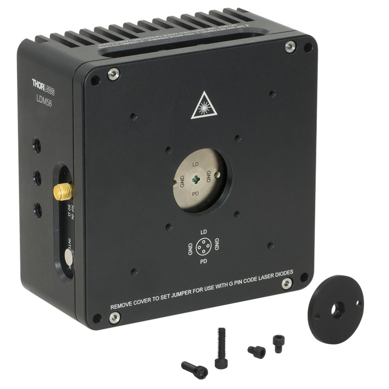 | 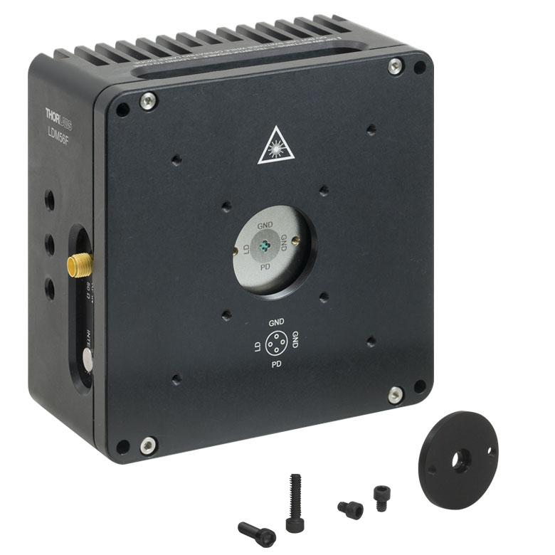 | 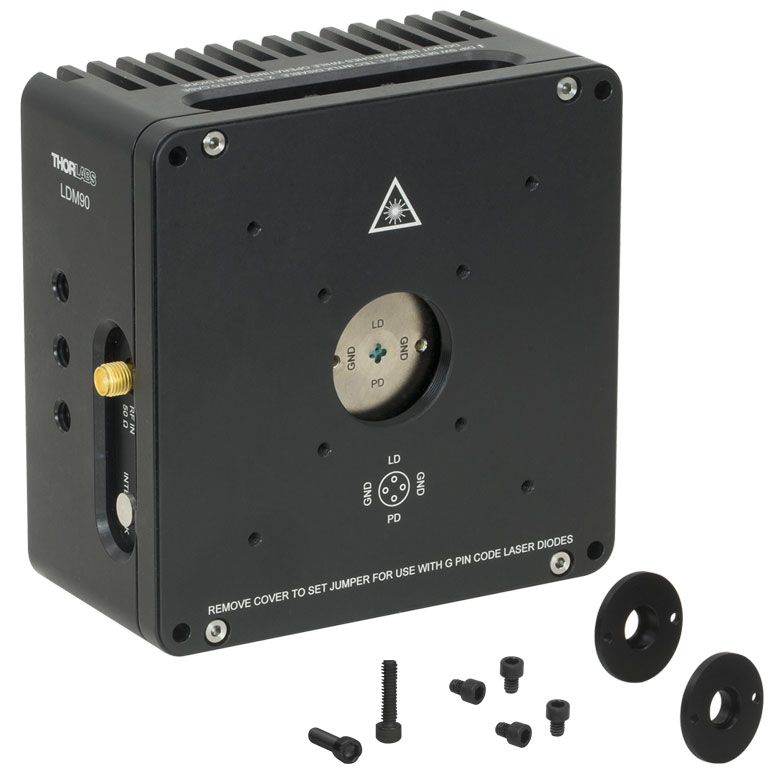 |  |  | |
| Laser Diode | |||||||
| Supported Laser Diode Package(s) | Ø3.8 mm | Ø5.6 mm | Ø5.6 mm | Ø9 mm | Ø5.6 mm and Ø9 mm | Ø5.6 mm and Ø9 mm | |
| Supported Pin Configuration(s) | G | A, B, C, D, E, Ga, H (Switch Selectable) | F and G (Switch Selectable) | A, B, C, D, E, Ga, H (Switch Selectable) | A, B, C, D, E, and H | A, B, C, D, E, G, and H (Some Modification Necessary for G Style)b | |
| Maximum Laser Current (Tambient = 25 °C) | 1 A | 2 A | 500 mA | 200 mA | |||
| RF Modulation Frequency Rangec | 100 kHz to 500 MHz | 100 kHz to 600 MHz | N/A | 200 kHz to 1 GHz | |||
| Temperature Controller | |||||||
| TEC Heating/Cooling Capacity (Tambient = 25 °C) | 8 W | 8 W | 2 W | 0.5 W | |||
| Temperature Adjustment Range | - | 0 to 70 °C | 20 to 30 °C | ||||
| General Specifications | |||||||
| Laser Interface | DB9 Female | ||||||
| TEC Interface | DB9 Male | N/Ad | |||||
| Compatible Current and Temperature Controllers | LDC Series and T-Cube LD Controllerse, ITC Series Combined LD/TEC Controllersf, and Temperature Controllersf | LDC Series and T-Cube LD Series Controllerse | |||||
| Mounting Features | Imperial Mounts | 1/4"-20 Tapped Hole (9 Places) | 8-32 Tapped Holeg (4 Places) | 8-32 Tapped Hole (3 Places) | |||
| Metric Mounts | M6 x 1.0 Tapped Hole (9 Places) | N/A | M4 x 0.7 Tapped Hole (3 Places) | ||||
| Accommodations for Collimating Optics | SM1 (1.035"-40) Series Internal Thread; LDMXY Flexure Adapter (Sold Separately) | SM1 (1.035"-40) Series Internal Thread | |||||
| Cage System Compatibility | 4-40 Tap (8 Places) for 30 mm and 60 mm Cage Systems | 4-40 Tap (4 Places) for 30 mm Cage System | |||||
| Dimensions | 4.00" x 4.00" x 2.07" (101.6 x 101.6 x 52.6 mm) | 1.75" x 1.75" x 1.66" (44.5 x 44.5 x 42.1 mm) | 3.09" x 2.89" x 1.79" (78.5 x 73.3 x 45.5 mm) | ||||

 ズーム
ズームアノードとカソードの刻印が実際とは逆に刻印されています。上記日以降のご購入製品は
(上にカソード、下にアノードの刻印付きで)修正されています。刻印のみの違いであり、製品は同様に機能します。
- Ø3.8 mm TO-Can型半導体レーザに対応
- 標準の半導体レーザーパッケージ用フランジが付属
- 対応するピンコード: G
- 仕様の詳細は、上の「仕様」タブをご参照ください。

 ズーム
ズーム
Click to Enlarge
Figure G2.1 マウントLDM56F(/M)
- Ø5.6 mm TO-Can型半導体レーザに対応
- 標準の半導体レーザーパッケージ用フランジが付属
- 対応するピンコード:
- LDM56/M: A、B、C、D、E、G、H
- LDM56F/M: F、G
- 仕様の詳細は、上の「仕様」タブをご参照ください。
- 532 nm DPSS レーザ用の取付けフランジも別途ご用意。詳細は下記をご参照ください。
注)こちらのLDMシリーズは、ピグテール付きTO-Can型半導体レーザに対して温度制御が十分に機能しない可能性があり、また個体によっては装着ができない場合がございますのでご注意ください。ピグテール付き半導体レーザには、専用に設計されたTEC付きLDマウントLDM9LPのご利用をお勧めしております。

 ズーム
ズーム
 ズーム
ズーム| LDMXY Adapter Specifications | |
|---|---|
| Flexure | |
| Optic Cell Travel | ±1.0 mm |
| Optic Cell Threading | SM1 (1.035"-40) Through Tapped |
| XY Adjusters | M3 x 0.25 (250 μm/rev) |
| Slip Plate | |
| Slip Plate Travel | ±1.0 mm (Coarse Adjustment) |
| Cage Compatibility | 4-40 Taps (8 Places) for 30 mm and 60 mm Cage Systems |
| General | |
| Material | Aluminum |
| Dimensions | 4.00" x 4.00" x 0.60" (101.6 mm x 101.6 mm x 15.2 mm) |
| Mass | 0.33 kg (0.73 lbs) |
- SM1ネジをXY方向にフレクシャ移動(移動量:±1.0 mm)
- ケージシステム用タップ穴付きスリッププレートは可動部(移動量:±1.0 mm)とは別体
- 30 mmと60 mmケージシステム対応
- LDMシリーズの半導体レーザーマウント前面に直接取り付け可能
フレクシャーアダプタLDMXYはコリメート用光学素子などをXY方向に±1.0 mm移動させます。移動式光学セルはSM1ネジ付きで当社の非球面レンズアダプタや 非球面レンズが取り付けられます。前面のスリッププレート自体もSM1ネジ付きの光学セルとは独立にXY方向に±1.0 mm粗移動します。スリッププレートには30 mmおよび60 mmケージシステムに対応したケージロッド用ネジ穴があります。そのため、スリッププレートに取り付けたケージシステムの荷重は、フレクシャー機構部分から隔離されます。スリッププレートは4個の標準的なキャップスクリュを緩めて調整します。アダプタLDMXYを半導体レーザーマウントに取り付ける際にも4個の固定ネジを使用します。すべてのネジは2.0 mmボール(六角)ドライバや六角レンチが使用可能です。
Click to Enlarge
Figure G4.1 LDMXYは作動距離を伸ばしたいときやXY移動にお使いいただけます。
Click to Enlarge
Figure G4.2 XY方向のフレクシャ機構がSM1ネジ付きの光学セルを移動(ケージシステムのスリッププレートは固定)

 ズーム
ズーム
取付けフランジLDM56DJは、532 nm DPSSレーザを温度制御付きマウントLDM56/Mに取付けるために使用します。使用する際は、レーザDJ532-10またはDJ532-40をマウントLDM56/Mに取り付けます。フランジかマウント自体に付いている2つの2-56×3/8"のキャップスクリュで、マウントにフランジを取付けます。
注:こちらのフランジは温度制御付き半導体レーザーマウントLDM56/Mには付属しておりません。