 Products Home / 半導体レーザ用電流コントローラ(LDドライバ)、温度コントローラ、LDマウント / 組み込み用半導体レーザー(LD)ドライバー/コントローラー / 組み込み用半導体レーザー/温度コントローラー
組み込み用半導体レーザー/温度コントローラー
- Excellent Temperature Stability: <0.004 °C
- Adjustable P, I, & D Temperature Control Loop
- Analog Modulation of Laser Current up to 200 kHz
- Extensive Laser Diode Protection Features
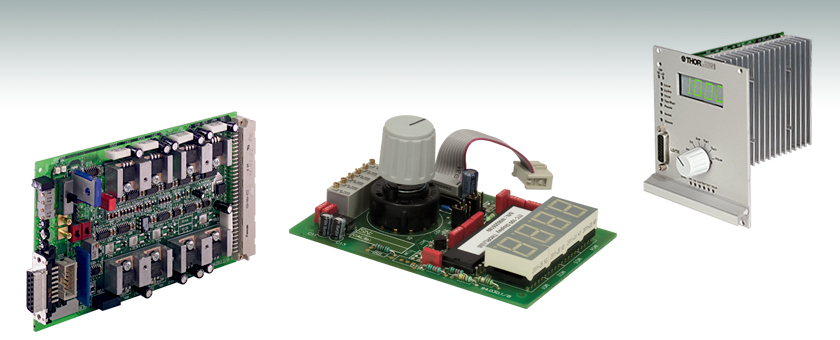
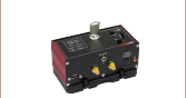
ITC102
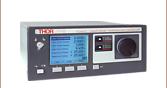
ITC100D
ITC102 with
ITC100D & ITC100F

Please Wait
特長
- 電流コントローラとTECコントローラの組合せ
- 最大電流値:200 mA、1 A、3 Aの3種類
- 定電流(CC)および定光出力(CP)モード
- 独立したP、I、Dの設定が可能なフルPIDフィードバックループを搭載
- 半導体レーザの損傷に対する様々な保護機能
- システムと簡単に統合するための標準的なピン配置
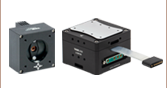
100 mm x 160 mmのボード型コントローラーシリーズは、低ノイズかつ低ドリフトの電流源と精密なTECコントローラとの組合せになっています。ミリ規格のボードは、お客様の製品に簡単に組み込めるよう設計されており、高いレーザ発光安定性が要求される製品やシステムに適しています。アナログインターフェイスで、パラメータ設定や読み出しが容易です。
半導体レーザ用コントローラーシリーズは、定電流(CC)モードと定光出力(CP)モードを持ち、全てのレーザとモニタ用ダイオードの極性(CG/AG)に対応します。 半導体レーザは15ピンD-Subコネクタを介してコントローラに取付けられます。 固定グラウンドレベル設計は雑音や過渡抑制、出力の安定性の面で優れた性能を発揮します。 レーザの駆動電流は外部制御信号によって変調できます。
内蔵の温度コントローラは、独立したP、I、Dの設定が可能なフルPIDフィードバックループを搭載しており、個別に最適化することができます。 様々な温度センサ(サーミスタ、温度トランスデューサAD590など)に対応しています。 標準的な64ピンPCBコネクタを介して、出力信号、アナログ制御入力信号、電源供給接続、温度センサ、熱電冷却素子にアクセス可能です。
アクセサリ
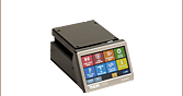
システム制御パラメータの確認や設定ができるよう、ディスプレイボード(ITC100D)、およびフロントパネル(ITC100F)も下記にてご用意しています。 さらに、当社の9ピンおよび15ピンYケーブル(CAB430)を用い、このコントローラとTEC付き半導体レーザーマウント製品シリーズを接続することができます。
詳細については、当社までお問い合わせください。
半導体レーザ用コントローラの仕様
| Item # | ITC102 | ITC110 | ITC133 |
|---|---|---|---|
| Current Control | |||
| Display Laser Current On | LED | ||
| Trim Potentiometers (15 Turn) | ILD, IPD Resp. PLD, ILD,LIM | ||
| Control Range of Laser Current | 0 to ±200 mA | 0 to ±1 A | 0 to ±3 A a |
| Compliance Voltage | >4 V | ||
| Setting Accuracy / Repeatability (Full Scale) | ±2% Typical / ±0.1% | ||
| Noise (10 Hz to 10 MHz, rms) | <2 µA | <6 µA | <25 µA |
| Drift (30 min, 0 to 10 Hz, Typical) | <20 µA | <100 µA | <300 µA |
| Temperature Coefficient | <50 ppm/°C | ||
| Power Control | |||
| Control Range Photo Diode Current | 5 µA to 2 mA | ||
| Accuracy / Repeatability (Full Scale) | ±2% Typical / ±0.1% | ||
| Photodiode Reverse Bias Voltage | 0 V or 5 V | ||
| Current Limit | |||
| Setting Range | 0 to >200 mA | 0 to >1 A | 0 to >3 A |
| Setting Accuracy / Repeatability (Full Scale) | ±2% Typical / ±0.1% | ||
| Analog Modulation Input | |||
| Input Resistance | 10 kΩ | ||
| Modulation Coefficient, CC | 40 mA/V ± 5% | 200 mA/V ± 5% | 600 mA/V ± 5% |
| Small Signal 3 dB Bandwidth, CC | DC to 200 kHz | DC to 50 kHz | DC to 20 kHz |
| Modulation Coefficient, CP | 0.4 mA/V ± 5% | ||
| TTL Modulation Input | |||
| Rise/ Fall Time | <10 µs | <50 µs | <100 µs |
| TTL Control Input | LD ON | ||
| Measurements and Control Outputs | |||
| Analog Measurement Values | ILD, IPD, ILD,LIM | ||
| Measurements Outputs | 0 to ±5 V | ||
| Measurements Accuracy (Typical, Load > 500 kΩ) | ±2% | ||
| TTL Control Outputs | LD ON, LIMIT | ||
| General Data | |||
| Supply Voltage / Current | ±12 to ±15 V / 2.3 A | ±12 to ±15 V / 3.1 A | ±12 to ±15 V / 3.1 A a |
| Operating Temperature | 0 to 40 °C | ||
| Storage Temperature | -40 °C to 70 °C (Non-Condensing) | ||
| Warm-Up Time for Rated Accuracy | 10 min | ||
| Dimensions (W x H x D) | 100 mm x 42 mm x 160 mm (Eurocard) | ||
| Weight | < 0.7 kg | ||
(全てのデータは、23 ± 5°Cで相対湿度45 ±15%の条件下で有効)
TECコントローラの仕様
| Item # | ITC102 | ITC110 | ITC133 |
|---|---|---|---|
| Temperature Control | |||
| Display TEC Current ON | LED | ||
| Trim Potentiometers (15 Turn) | ITEC,LIM, TSET / RSET | ||
| Trim Potentiometers (1 Turn) | P, I and D Share | ||
| TEC Output | |||
| Control Range of TEC Current | -2 A to +2 A | -2 A to +2 A | -3 A to +3 A a |
| Compliance Voltage | >6 V | ||
| Maximum Output Power | 12 W | 12 W | 18 W |
| Noise and Ripple | <1 mA | <1 mA | <3 mA |
| Thermistor Temperature Sensors | |||
| Control Range | 100 Ω to 80 kΩ | ||
| Setting Accuracy (Full Scale, Typical) | ±2% | ||
| Repeatability (Full Scale) | ±0.1% | ||
| Temperature Stability (Typical) | <2 Ω | ||
| IC Temperature Sensors AD590, AD592, & LM335 | |||
| Control Range | -20 °C to 80 °C | ||
| Setting Accuracy (Full Scale, Typical) | ±2% | ||
| Repeatability (Full Scale) | ±0.1% | ||
| Temperature Stability (Typical) | <0.004 °C | ||
| TEC Current Limit | |||
| Setting Range | 0 to ≥2 A | 0 to ≥2 A | 0 to ≥3 A |
| Accuracy (Typical) | ±5% | ||
| Temperature Control Inputs | |||
| Analog Control Input | TSET / RSET | ||
| Input Resistance | 10 kΩ | ||
| Input Coefficient Thermistor | 16 kΩ/V | ||
| Input Coefficient IC-Sensor | 20 °C/V | ||
| TTL Control Input | TEC ON | ||
| Measurement and Control Outputs | |||
| Analog Outputs | TSET/RSET, TACT/RACT, ITEC,LIM (ITEC, ΔT/ΔR) | ||
| Measurement Accuracy (Typical, Load > 500 kΩ) | ±2% | ||
| TTL Control Outputs | TEC ON, TEMP OK | ||
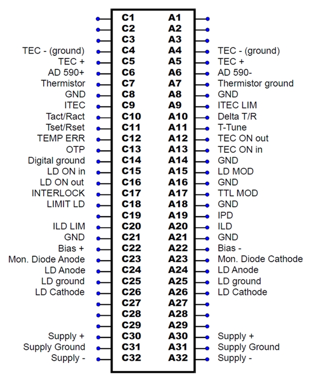
ST1 64ピン I/Oジャック
ST2 15ピン I/Oジャック
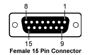
| Pin | Connection | Pin | Connection |
|---|---|---|---|
| 1 | Interlock | 9 | Bias (-) |
| 2 | Monitor Diode Cathode | 10 | Laser diode cathode (polarity AG) |
| 3 | Laser Diode Ground | 11 | Laser diode anode (polarity CG) |
| 4 | Monitor Diode Anode | ||
| 5 | Interlock Ground | 12 | Bias (+) |
| 6 | AD 590 (+) | 13 | AD 590 (-) |
| 7 | TEC (+) | 14 | Thermistor Ground |
| 8 | TEC (-) (ground) | 15 | Thermistor |
ST4 - SMBオス
半導体レーザ変調入力

-5 ... +5 V
40/200/600 mA/V (ITC102/110/133)
ST5 - SMBメス
温度調整入力
-5 ... +5 V
20° C/V / 16 kΩ/V (Transducer/Thermistor)
| ITC102 | ITC110 | ITC133 | Part |
|---|---|---|---|
| x | OEM Laser Diode and Temperature Controller, ±200 mA / 12 W (ITC102) | ||
| x | OEM Laser Diode and Temperature Controller, ±1 A / 12 W (ITC110) | ||
| x | OEM Laser Diode and Temperature Controller, ±3 A / 18 W (ITC133) | ||
| x | x | x | Operating Manual |
| Posted Comments: | |
Rajin Pradhan
(posted 2024-04-05 16:31:41.4) Hi, I recently bought the following parts: ITC133, ITC100D. I followed the instructions on Operating manual, 6.2 ITC100D Jumper settings, and set the jumper at 2nd position for ITC133, but when I turn on the device, Display works fine for digits, but the LED of decimal point doesn't turn ON. Is there something I might be doing wrong? How to find the issue if any? dpossin
(posted 2024-04-08 09:36:31.0) Dear Rajin,
Thank you for your feedback. I´ll reach out to you directly in order to discuss the details. 诗崎 王
(posted 2023-11-22 18:27:05.89) 我将ITC-102接入15V/3A的电源,同时ITC-100也在102上,电源通入后,102上的LED2没有正常工作,ITC-100的LED屏显示,我对各参数进行调试,ITC-100没有变化。我又分别对电压和电流用万用表进行了测量,电压输入为15V,电流为0.15A。 fmortaheb
(posted 2023-11-22 11:59:21.0) Thank you very much for contacting us. An application engineer from our team in China will discuss this directly with you. Kenny Gregory
(posted 2021-07-19 19:03:45.787) This is specifically for the ITC102.
The manual diagrams only show the unit working with an AD590 and a thermistor together. If I only have an AD590 is the thermistor required? wskopalik
(posted 2021-07-23 03:28:26.0) Thank you very much for your inquiry!
The ITC102 as well as the other ITC100 boards only need one temperature sensor for correct operation. So either a thermistor or an IC temperature sensor (AD590, AD592, LM335) is sufficient. You do not need both. There is a switch (S3) on the board to select which type of sensor is connected.
I will contact you directly to provide further assistance. Ludovic Angot
(posted 2020-07-14 08:43:10.653) Can the ITC133 be used with any L.D. pin code, in particular pin code G? On pages 15 to 17 of the current version of the manual (3.2, jun 2020), I see no mention and no configuration example of using a LD without photodiode. If this is possible, is there any particular hardware setting to apply? MKiess
(posted 2020-07-14 09:15:32.0) This is a response from Michael at Thorlabs. Thank you very much for your inquiry. On page 15 to page 17 in the current manual, only the general, possible configurations of the combinations of laser and monitor diode are shown. It is also possible to connect a laser diode with respect to ground, individually.
You can also use the CAB430 to connect the ITC133 controller with a Thorlabs' laser mount suitable for G-style laser diodes, which can be found under the following link:
https://www.thorlabs.de/navigation.cfm?guide_ID=35
I have contacted you directly to discuss the connection in your specific case. nick Yang
(posted 2020-05-26 21:55:23.467) Hi, I'm requesting inquiry in terms of operating ITC110. Currently, we are using a gain chip that has only Thermistor and not transducer. Is there a way for us to interpret thermistor resistance value in terms of temperature Celsius? wskopalik
(posted 2020-05-29 06:32:27.0) This is a response from Wolfgang at Thorlabs. Thank you very much for your inquiry!
The display ITC100D as well as the analog output on the ITC110 will unfortunately only return the resistance value when a thermistor is used as a temperature sensor. It cannot be converted into a temperature value automatically. Thermistors have a specified relation between their resistance and the temperature which is usually given in their data sheets. So you could manually convert the resistance value to a temperature value by using this relation.
I will contact you directly to provide further assistance. Youngjin Ahn
(posted 2020-02-20 03:52:20.213) Hi, our lab have purchased the ITC110 product with ITC100D. However, we are having trouble to turn on the LED display panel from the ITC100D.
We have connected two 15V power supplies in series in order to supply the voltage range between -15V to +15V. Also, we have designed the circuit by following the schematic diagram given in the manual. We have, connected this circuit with ITC110 and connected -15V, GND, and +15V to the pins described in the manual.
By considering that circuit that we made is correct, could you recommend any method to further check if there is any issues why the LED panel on ITC100D doesn't turn on. Sincerely, Youngjin Ahn dpossin
(posted 2020-03-04 09:10:50.0) Dear Ahn,
Thank you for your feedback. I have contacted you via E-Mail in order to discuss your setup with you and provide further help. damien.marchand
(posted 2019-01-17 08:53:18.96) Hi, We bought the following parts for laser diode control: Part numbers are: ITC133.
We use it on Laser pulsed diode in current mode. Is it possible to use mode power constant on this type of laser ( pulsed) ? Thanks for your answer swick
(posted 2019-01-29 05:41:56.0) This is a response from Sebastian at Thorlabs. Thank you for the inquiry. It is possible to control Laserdiodes in constant-power (CP) mode and modulate it at the same time but modulation bandwidth will be lower compared to constant-current (CC) mode. It depends on the pulsed-type laser diode and corresponding driving parameters if CP-mode could be used. I contacted you directly to provide assistance. gksthf666
(posted 2018-11-15 21:42:01.943) To whom it may concern,
Hello, I'm Hansol Jang and I have some question about ITC110.
Recently we've bought some of ITC110 but does not use yet because of supply voltage problem.
The supply voltage and current shown in spec sheet are +-12 to 15 V and 3.1A respectively.
Following are my question.
1. Should we supply +15V and -15V at a same time?
2. Required current of each voltage channel (+15 and -15V) is 3.1A right?
3. We are going to supply voktage to ITC110 with SMPS but it is very hard to find products which satisfy both two channel output (+15 and -15V) and current of 3.1A or more. Most of multi channel SMPS have different current level according to output channel (ex) +15V, 2A and -15V, 0.5A). Could you recommend supplying method or instruments (such as SMPS, AC-DC converter..) for ITC110 please?
4. Finally we need to use two ITC110 at a same time so much higher current level is required I think.
Sincerely,
Hansol Jang wskopalik
(posted 2018-12-05 09:02:40.0) This is a response from Wolfgang at Thorlabs. Thank you very much for your inquiry!
Please find the answers to your questions below:
1. Yes, you need to connect +15V, GND and -15V at the same time to the pins described in the manual (A30 - A32, C30 - C32).
2. Yes, the current would need to be 3.1 A for each voltage channel.
3. You can e.g. use a lab power supply to supply the ITC. These are available for different voltage and current ranges. So you would need to make sure that the particular power supply can provide the needed current and voltage level.
4. Each ITC110 needs to be supplied with the required current at the required voltage. So depending on how you connect the ITCs and the power supplies, the total current would double. ergulmuhammed
(posted 2018-09-07 05:42:47.003) Hİ, I have mistyped twice in my previous post. Please discard it and consider this one here: We bought the following parts for laser diode control: Part numbers are: ITC102 ITC100D ITC100F CAB430 LDM9LP and we have combined ITC102,ITC10D,ITC100F and tried to run. Although I do supply the required voltage, Led2 (indicator of Vcc) does not light but the 7-segment display works, but it does not show reasonable values and the values do not change even though I change the potentiometer. Where am I doing wrong? swick
(posted 2018-09-14 03:33:22.0) This is a response from Sebastian at Thorlabs. Thank you for the inquiry.
I contacted you directly for troubleshooting. ergulmuhammed
(posted 2018-09-06 08:48:48.523) Hİ, We bought the following parts for laser diode control: Part numbers are: ITC102 ITC100D ITC100F CAB430 LDM9LP and we have combined ITC102,ITC10D,ITC100F and tried to run.
Although I do not supply the required voltage, Led2 does not light but the 7-segment display works, but it does not show reasonable values and the value does not change even though I do not change the potentiometer.
Where am I doing wrong? swick
(posted 2018-09-14 03:36:45.0) This is a response from Sebastian at Thorlabs. Thank you for the inquiry. I contacted you directly for troubleshooting. leticia.tarruell
(posted 2018-05-11 19:42:55.61) Hello,
We do have a broken ITC 133. Is it possible to ship it for repair? YLohia
(posted 2018-05-11 03:06:33.0) Hello, thank you for contacting Thorlabs. We are sorry to hear that. Please contact your local Thorlabs Tech Support team (europe@thorlabs.com) for troubleshooting and potential RMA for repair. francisco.rodriguez
(posted 2018-03-19 17:56:41.697) Dear sirs,
We have purchased this product for testing it in our lab and it is now runing quite good. We have now to make an integration and select a compact power supply. Could you tell us what is the maximum tolarated ripple at the input?
Thank you in advance
Best Regards
Francisco swick
(posted 2018-04-10 04:04:50.0) This is a response from Sebastian at Thorlabs. Thank you for the inquiry. For ITC100-Series we recommend to use PSU with <50mV ripple. nluo
(posted 2017-10-26 14:08:12.467) Hi,
this is Nan with Calient. We bought the following parts for laser diode control:
Part numbers are:
ITC102
ITC100D
ITC100F
CAB430
But there is no user manual or how can we adjust laser diode current or power. Where can we have user manual?
Thanks
Nan wskopalik
(posted 2017-10-27 07:19:17.0) This is a response from Wolfgang at Thorlabs. Thank you very much for your inquiry.
You can find all the available documents for a product when you click on the red document icon left of the part number in the overview tab of this website. This will open a pop-up window with links to the documents. For all other products on the website this is the same.
I will also contact you directly. dawnjlu
(posted 2015-09-25 23:14:57.653) Hello,
I was wondering how to remove the large knob on ITC100D when I want to install ITC100F to the ITC100D. I have tried several methods, but all failed, the knob looks fixed on ITC100D very well.
Thank you.
Li shallwig
(posted 2015-09-28 11:07:01.0) This is a response from Stefan at Thorlabs, Thank you very much for your feedback. The head of the control knob with the black line is a cap which is just plugged in. By removing this cap you have access to a screw which fixes the knob to the board. I will contact you directly to check if there are any further questions. nursidik.yulianto
(posted 2015-09-09 23:46:41.663) How to measure temperature at celcius degree. i use ITC 102 and ITC 100D for DFB laser 0-70C shallwig
(posted 2015-09-10 04:23:13.0) This is a response from Stefan at Thorlabs. Thank you very much for your inquiry. There are several ways to get the actual temperature with the ITC102 displayed.
In the manual on page 6 http://www.thorlabs.de/thorcat/7100/ITC102-Manual.pdf you can find the TEC specifications and temperature sensors control range. With the ITC100D display panel connected you can display the “Set” and “Actual” temperature on the display. Please check that the Jumpers are set as described in the manual from page 45-46:
For the ITC102 both jumpers ILD and ILim have to be at position 1.
With the knob you can display from counter- clockwise to clockwise following parameters:
Photo diode current IPD
Laser diode current ILD
Laser diode limit current ILIM
Set temperature1) (or resistance2)) value TSET
Actual temperature1) (or resistance2)) value TACT
TEC limit current ITLIM
For higher display accuracy you should re-calibrate the ITC100D from time to time. For adjusting Tact bring your temperature sensor to a well-defined temperature and adjust the ITC100D
reading to that temperature using potentiometer P5. P5 is the second potentiometer from the right below the turning knob, please see also the picture in the manual on page 45.
Alternatively you can also read out the temperature from the 64 pin connector directly at Pin C10 (see manual page 19 for the pin diagram).
The actual temperature (TACT ) can be calculated with the conversion factor 50mV/°C from the voltage drop (-1 ... +4 V ) along a load resistance, we recommend to use at least 500kOhm load.
I will contact you directly to check if you have any further questions. yangkwanmo0109
(posted 2014-02-24 16:16:30.4) I'm trying to figure out how to play with the TEC mode of ITC100. When I change the Tset to a certain value (I changed it to 40C when Tact was at 26.1C), the Tact seems to change super slowly. Is this normal? Reading through the manual (the polarity part in the TEC section), it seems like the Tact reaching the Tset seems pretty fast, so that we can check the polarity of the system.
Also, it seems like Tact is increasing when LD is on, and is decreasing when LD is off. I am having trouble with the temperature control. Any help? jvigroux
(posted 2014-02-24 10:52:33.0) A response from Julien at Thorlabs: Thank you for your feedback! Based on the description of the problem, it seems that the settings of the temperature feedback loop might be the issue. the user can set the PID as well as the maximal TEC current so as to adapt the TEC driver to the system considered. I will contact you directly to discuss the exact details of your set up. leticia.tarruell
(posted 2013-12-17 15:39:44.22) Hello,
Is there any plan to extend the OEM ITC controllers to higher current ranges? It would be very helpful to be able to drive TA chips with them, and many require up to 4.5A tschalk
(posted 2013-12-19 09:08:26.0) This is a response from Thomas at Thorlabs. Thank you very much for your inquiry. There are no plans to extend the current ranges of these controllers. We could offer you a special item which can provide a higher current. I will contact you directly with more detailed information. sebastien.avila
(posted 2013-10-02 11:26:18.64) Hello,
We want to use the ITC133 in a portable application and our power supply comes from a 24VDC battery pack.
Do we need to convert the voltage into +/-12VDC ou simply +12VDC?
Is there a power supply that you can reccomend us to use the ITC133 from a 24VDC battery?
Thank you very much.
Best Regards,
S. AVILA. jlow
(posted 2012-09-07 08:40:00.0) Response from Jeremy at Thorlabs: While the ITC133 can be used to drive the L915P1WJ, you will still need other devices such as a TEC mount, adequate heat sink (and maybe a fan to cool the fins of your heat sink as well). You would also need a power supply that can provide the adequate current (please see page 11 of the manual for the specifications). jintaixun
(posted 2012-09-07 03:31:59.0) Hi
I'm a university student from South Korea and have an enquiry about ITC133
In my bio-optics laboratory, I've got some high-power laser diodes such as L915P1WJ and others pin code A or D.
Can I drive them with ITC133 safely without any other devices? bdada
(posted 2011-04-07 15:45:00.0) Response from Buki at Thorlabs:
Thank you for your feedback. We have corrected the specification of the ITC133 current control range. user
(posted 2011-04-07 15:25:41.0) Current control range spec for the ITC133 shows units of mA while it should be A. Laurie
(posted 2009-04-24 12:11:09.0) Response from Laurie at Thorlabs to hase: Thank you for your inquiry for our OEM diode and temperature controllers. We do have several customers that use this instrumentation for telecom fiber testing applications, as well as a leading manufacturer of subsystems that implements these. Unfortunately, we do not have any specific data for the mean time between failures of these items. If you can provide us with your requirements, we will discuss your application with our engineers to see if we can ensure that this item will meet your needs. hase
(posted 2009-04-15 04:53:48.0) Could you give me the reliability data of ITC102 and PDB140C, such as MTBF? I am considering if they can be integrated into a system for telecom fiber testing application. |
半導体レーザーコントローラーセレクションガイド
Table 137Aと137B は、当社の半導体レーザ用コントローラおよびデュアル半導体レーザ/温度コントローラの主な仕様の一覧です。詳しい内容や仕様について、またはご注文の際には表内の型番をクリックしてご確認ください。
| Table 137A Current Controllers | ||||||
|---|---|---|---|---|---|---|
| Item # | Drive Current | Compliance Voltage | Constant Current | Constant Power | Modulation | Package |
| LDC200CV | 20 mA | 6 V | External | Benchtop | ||
| VLDC002 | 25 mA | 5 V | - | Int/Ext | OEM | |
| LDC201CU | 100 mA | 5 V | External | Benchtop | ||
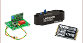
| LD2000R | 100 mA | 3.5 V | - | External | OEM | |
| EK2000 | 100 mA | 3.5 V | - | External | OEM | |
| LDC202C | 200 mA | 10 V | External | Benchtop | ||
| KLD101 | 230 mA | ≤10 V | External | K-Cube® | ||
| IP250-BV | 250 mA | 8 Va | External | OEM | ||
| LD1100 | 250 mA | 6.5 Va | - | -- | OEM | |
| LD1101 | 250 mA | 6.5 Va | - | -- | OEM | |
| EK1101 | 250 mA | 6.5 Va | - | -- | OEM | |
| EK1102 | 250 mA | 6.5 Va | - | -- | OEM | |
| LD1255R | 250 mA | 3.3 V | - | External | OEM | |
| LDC205C | 500 mA | 10 V | External | Benchtop | ||
| IP500 | 500 mA | 3 V | External | OEM | ||
| LDC210C | 1 A | 10 V | External | Benchtop | ||
| LDC220C | 2 A | 4 V | External | Benchtop | ||
| LD3000R | 2.5 A | -- | - | External | OEM | |
| LDC240C | 4 A | 5 V | External | Benchtop | ||
| LDC4005 | 5 A | 12 V | Int/Ext | Benchtop | ||
| LDC4020 | 20 A | 11 V | Int/Ext | Benchtop | ||
| Table 137B Dual Temperature and Current Controllers | |||||||
|---|---|---|---|---|---|---|---|
| Item # | Drive Current | Compliance Voltage | TEC Power (Max) | Constant Current | Constant Power | Modulation | Package |
| VITC002 | 25 mA | 5 V | >2 W | - | Int/Ext | OEM | |
| ITC102 | 200 mA | >4 V | 12 W | Ext | OEM | ||
| ITC110 | 1 A | >4 V | 12 W | Ext | OEM | ||
| ITC4001 | 1 A | 11 V | >96 W | Int/Ext | Benchtop | ||
| CLD1010LPa | 1.0 A | >8 V | >14.1 W | Ext | Benchtop | ||
| CLD1011LPb | 1.0 A | >8 V | >14.1 W | Ext | Benchtop | ||
| CLD1015c | 1.5 A | >4 V | >14.1 W | Ext | Benchtop | ||
| ITC4002QCLd | 2 A | 17 V | >225 W | Int/Ext | Benchtop | ||
| ITC133 | 3 A | >4 V | 18 W | Ext | OEM | ||
| ITC4005 | 5 A | 12 V | >225 W | Int/Ext | Benchtop | ||
| ITC4005QCLd | 5 A | 20 V | >225 W | Int/Ext | Benchtop | ||
| ITC4020 | 20 A | 11 V | >225 W | Int/Ext | Benchtop | ||
当社では製品組み込み用あるいはラックマウントの半導体レーザ電流&温度コントローラ(組み込み用モジュール、PRO8電流コントロールモジュール、PRO8電流&温度コントロールモジュール)もご用意しております。

 ズーム
ズーム| Item # | ITC102 | ITC110 | ITC133 |
|---|---|---|---|
| Control Range of Laser Current | 0 to ± 200 mA | 0 to ± 1 A | 0 to ± 3 A |
| Maximum TEC Power | 12 W | 12 W | 18 W |
詳細は「LD仕様」タブおよび「TEC仕様」タブをご覧ください。

 ズーム
ズーム
ITC100Dは、ITC100シリーズのコントローラに接続して、システムの制御パラメータを設定するための別売りディスプレイボードです。ITC100シリーズのコントローラ用フロントパネルITC100Fも販売しています。制御ボードとディスプレイボードの両方を覆い、コントローラの使い勝手を向上させます。
ITC100Fを取り付ける前に、アナログ出力制御用の大きなノブをITC100Dから一旦取り外してください。取り外すには、まず黒い線の書かれたノブの上蓋をこじ開けてください。そうすることで、パネルにノブを固定するネジが露出します。ITC100F取り付け後、アナログ制御ノブを元の位置に戻すとシステムの操作が行えます。
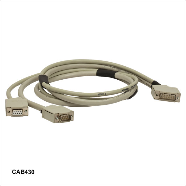
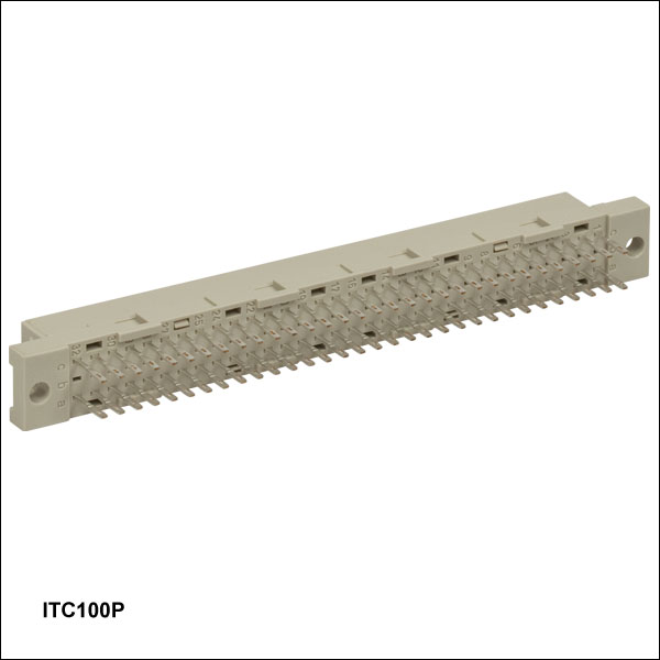
ケーブルCAB430は、当社のレーザーマウントにITC100シリーズのコントローラを接続するのにご使用いただけます。 ITC100Pは、半導体レーザ、パワーモニタ用フォトダイオード、TEC素子用のITCシリーズ入力/出力機能アレイにアクセス可能な取り換え用の64ピン メス型のDINコネクタです。
| Pin # | CAB430 (15 Pin) | CAB430 (9 Pin) | CAB430 (9 Pin) |
|---|---|---|---|
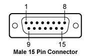 | 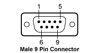 | 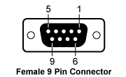 | |
| 1 | Interlock and Status LASER ON/OFF | Interlock and Status LASER ON/OFF | N.C. |
| 2 | Photodiode Cathode | Photodiode Cathode | Thermistor (+) |
| 3 | Laser Diode Ground | Laser Diode Ground | Thermistor (-), LM 135/335 (-), Ground |
| 4 | Photodiode Anode | Photodiode Anode | TEC (+) |
| 5 | Ground for Pin 1 | Ground for Pin 1 | TEC (-) |
| 6 | Transducer AD 590/592 (+), LM 135/335 (+) | Bias (-) | N.C. |
| 7 | TEC (+) | Laser Diode Cathode (with Polarity Anode Grounded - AG) | Transducer AD 590/592 (-), LM 135/335 (+) |
| 8 | TEC (-) | Laser Diode Anode (with Polarity Cathode Grounded - CG) | N.C. |
| 9 | Bias (-) | Bias (+) | Transducer AD 590/592 (+), LM 135/335 (+) |
| 10 | Laser Diode Cathode (with Polarity Anode Grounded - AG) | ||
| 11 | Laser Diode Anode (with Polarity Cathode Grounded - CG) | ||
| 12 | Bias (+) | ||
| 13 | Transducer AD 590/592 (-), LM 135/335 (+) | ||
| 14 | Thermistor (-), LM 135/335 (-), Ground | ||
| 15 | Thermistor (+) |