 Products Home / 半導体レーザ用電流コントローラ(LDドライバ)、温度コントローラ、LDマウント / 組み込み用半導体レーザー(LD)ドライバー/コントローラー / LDドライバーIC、SMTパッケージ
LDドライバーIC、SMTパッケージ
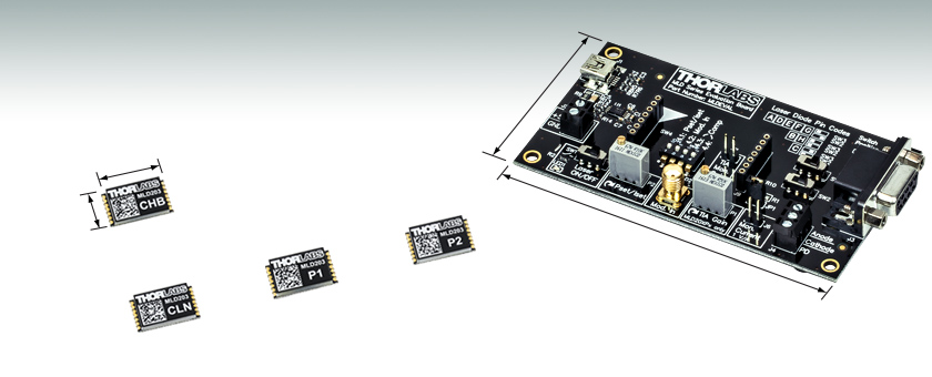
- Compact, Highly Integrated Laser Diode Drivers
- 14-Pin SMT Package Enables Quick Automated Assembly
- Designed for OEM, Custom, and Embedded Systems
- Volume Pricing Available
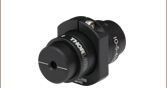
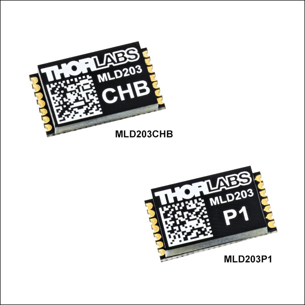
MLD203CHB
Constant Current & High Bandwidth
MLD203CLN
Constant Current & Low Noise
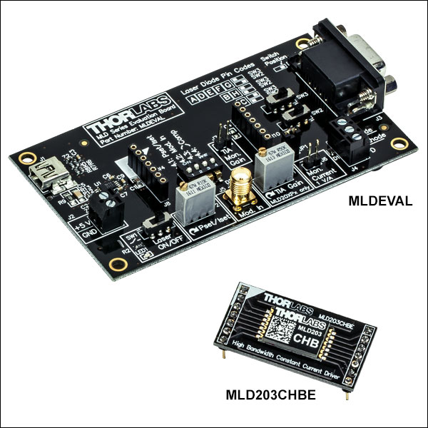
MLDEVAL
Evaluation Board
MLD203P1
Constant Power for Pin Codes A, B, and F
MLD203P2
Constant Power for Pin Codes C and D
17.0 mm
10.0 mm
56.0 mm
100.0 mm


Please Wait
| Feature Comparisona | ||||
|---|---|---|---|---|
| Item # | MLD203CHB | MLD203CLN | MLD203P1 | MLD203P2 |
| Key Features | Constant Current & High Bandwidth | Constant Current & Low Noise | Constant Power | Constant Power |
| Current Noise (RMS) | 12 µA | 3 µA | 3 µA | 3 µA |
| Modulation Bandwidth (3 dB) | DC to 100 kHz | DC to 1 kHz | N/A | N/A |
| Laser Pin Codes (Click for Diagram) | All (A through H) | All (A through H) | A, B, and F | C and D |
| Data Sheet (Click for PDF) | ||||
特長
- 3 Vのコンプライアンス電圧における最大駆動電流は200 mA
- 光出力は外部電圧、固定抵抗、可変抵抗によって調整可能
- ソフトスタートおよびブラウンアウト保護機能がレーザを過渡電流から保護
- システムへの組み込みが可能な17.0 mm × 10.0 mm × 2.8 mmのコンパクトなパッケージ
- 試験用途向けに評価ボードもご用意
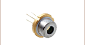
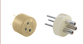
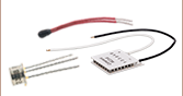
- TO-Can型半導体レーザ、半導体レーザ用ソケット、非球面レンズを使用した小型のアセンブリに対応
こちらの組み込み用半導体レーザードライバは、表面実装デバイス(SMD)用に一定かつ低ノイズの駆動電流を供給します。最大で200 mAの駆動電流、3 Vのコンプライアンス電圧、ならびに100 kHzまでの変調帯域幅をサポートしています(右の表をご参照ください)。各ドライバは、14ピンの表面実装技術(SMT)によるパッケージに収容されており、5 Vの供給電圧で駆動します。17.0 mm × 10.0 mm × 2.8 mmとコンパクトな機構は、めっきハーフホールコネクタを使用しているため、表面実装や電気接続を容易に行えます。
当社のドライバはシステムに簡単に組み込むことができ、ソフトスタートおよびブラウンアウト保護機能により、半導体レーザに予期せぬ高周波過渡電流が伝送されるのを防ぎます。ドライバの駆動設定値は供給電圧によって制御されるため、レーザの光出力は組立て時(外部抵抗により)または調整時(外部制御電圧または可変抵抗により)に設定できます。個々のドライバおよび半導体レーザに対して、独立に基準電圧出力値が設定されます。
こちらのドライバは、定電流モデルと定光出力モデルをご用意しています。モデルごとの特長の概要は右表でご覧いただけます。また、各モデルの仕様の詳細は「仕様」タブをご参照ください。
評価ボード
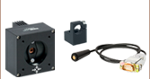
当社では、ドライバの性能特性をテストするための評価ボードをご用意しております。ボードには半導体レーザ接続用のメス型DB9コネクタやネジターミナル、ドライバの動作設定を行うトリムポット、そして変調信号入力用のメス型SMAコネクタが付いています。電源はUSBまたは5 VDCの電源から供給されます。14ピンSMT配列のドライバを評価ボードのソケットに合うよう予めドーターボードに取り付けたドライバもご提供しております。
評価ボード
| Item # | MLDEVAL |
|---|---|
| Supply Voltage | 5 VDC ± 5% |
| Operating Temperature | 0 °C to +40 °C |
| Storage Temperature | -40 °C to +70 °C |
| Dimensions | 105.8 mm × 56.0 mm × 14.1 mm |
| Weight | 40 g |
絶対最大定格(すべてのドライバ)
| Absolute Maximum Ratings | |
|---|---|
| Supply Voltage | 6 V |
| Power Dissipation | 750 mW |
| Operating Temperature | -25 °C to +90 °C |
| Storage Temperature | -40 °C to +100 °C |
定電流半導体レーザ(LD)ドライバ
| Item # | MLD203CHB(E) | MLD203CLN(E) | Notes |
|---|---|---|---|
| Operating Mode | Constant Current | - | |
| Laser Pin Codes | All (A through H) | See Diagram Below | |
| Supply Voltage | 4.5 V to 5.5 V | - | |
| Laser Current | |||
| Current Range | 0 mA to 200 mA | - | |
| Compliance Voltage | 3.0 V (Max) | For 5 V Supply Voltage | |
| Accuracy | ±(2% + 1 mA) [Typical] | Full Scale; After 10 Minute Warm-Up | |
| Repeatability | ±0.1% | Full Scale | |
| Noise | 12 µA (RMS) | 3 µA (RMS) | 10 Hz to 10 MHz; Measured with a 10 Ω Resistor |
| Drift | 20 µA | 30 Minutes, 0 to 10 Hz, Tamb = 25 °C | |
| Temperature Coefficient | 100 ppm/°C | - | |
| Laser Current Setpoint and Modulation | |||
| Input Impedance | 1 MΩ | - | |
| Input Voltage Range | 0 V to 2.5 V | - | |
| Input Voltage Offset | 90 mV (Typical) | - | |
| Modulation Bandwidth | DC to 100 kHz | DC to 1 kHz | 3 dB; Measured with a 10 Ω Resistor |
| Modulation Coefficient | 80 mA/V ± 5% | - | |
| Laser Current Reference Output | |||
| Laser Current Coefficient | 1 mV/mA | For 1 Ω Resistor in Series | |
| Measurement Accuracy | 1% | For ≥10 kΩ Load | |
| Physical Data | |||
| Operating Temperature | -20 °C to +70 °C | Non-Condensing | |
| Storage Temperature | -40 °C to +100 °C | Non-Condensing | |
| Warm-Up Time for Rated Accuracy | 10 Minutes | - | |
| Dimensions of SMT Package | 17.0 mm × 10.0 mm × 2.8 mm | - | |
| Dimensions of Daughterboard with SMT Package | 38.0 mm × 19.0 mm × 12.9 mm | MLD203CHBE and MLD203CLNE Only | |
| Weight | 1.0 g | - | |
定光出力半導体レーザ(LD)ドライバ
| Item # | MLD203P1(E) | MLD203P2(E) | Notes |
|---|---|---|---|
| Operating Mode | Constant Power | - | |
| Laser Pin Codes | A, B, and F | C and D | See Diagram Below |
| Supply Voltage | 4.5 V to 5.5 V | - | |
| Laser Current | |||
| Current Range | 0 mA to 200 mA | - | |
| Compliance Voltage | 3.0 V (Max) | For 5 V Supply Voltage | |
| Noise | 3 µA (RMS) | 10 Hz to 10 MHz Measured with 10 Ω Resistor in Series with L635P5 Laser Diode (for MLD203P1) or with L637P5 Laser Diode (for MLD203P2) | |
| Laser Power Control | |||
| Current Range of Monitor Photodiode | 2 µA to 2 mA | - | |
| Accuracy | ±2% (Typical) | Full Scale; After 10 Minute Warm-Up | |
| Repeatability | ±0.1% | Full Scale | |
| Drift | 20 nA | 24 Hours, Tamb = 25 °C Measured at P = 4.5 mW with L635P5 Laser Diode (for MLD203P1) or with L637P5 Laser Diode (for MLD203P2) | |
| Temperature Coefficient | 55 ppm/°C | - | |
| Laser Current Setpoint | |||
| Input Impedance | 1 MΩ | - | |
| Input Voltage Range | 0 V to 2.5 V | - | |
| Voltage Conversion Coefficient Range | 8 µA/V to 800 µA/V ± 5% | Adjustable | |
| Laser Current Reference Output | |||
| Laser Current Coefficient | 1 mV/mA | For 1 Ω Resistor in Series | |
| Measurement Accuracy | 1% | For ≥10 kΩ Load | |
| Physical Data | |||
| Operating Temperature | -20 °C to +70 °C | Non-Condensing | |
| Storage Temperature | -40 °C to +100 °C | Non-Condensing | |
| Warm-Up Time for Rated Accuracy | 10 Minutes | - | |
| Dimensions of SMT Package | 17.0 mm × 10.0 mm × 2.8 mm | - | |
| Dimensions of Daughterboard with SMT Package | 38.0 mm × 19.0 mm × 12.9 mm | MLD203P1E and MLD203P2E Only | |
| Weight | 1.0 g | - | |
LDのピンコード
すべてのピンコード(A~H)は、定電流動作に対応します。ピンコードA、B、C、DならびにFにはモニタ用フォトダイオードが含まれるため、定光出力動作にも対応します。
半導体レーザ(LD)ドライバ
ピン配列
このピン配置は、刻印のある面を上にした状態でドライバを上から見た図です。
ランドパターンデータ
| MLD203CHB & MLD203CLN Constant Current Drivers | ||
|---|---|---|
| Pin | Name | Description |
| 1 | VIN1 | Supply Voltage Input 1 |
| 2 | VIN2 | Supply Voltage Input 2 |
| 3 | GND1 | Supply Voltage Ground |
| 4 | GND2 | Return Pin (Ground) for Pin 6 |
| 5 | VREFOUT | Reference Output Voltage (+2.5 V) |
| 6 | ISET | Input Voltage for Current Setpoint |
| IMOD | Input Modulation Voltage | |
| 7 | NC | No Connection |
| 8 | NC | No Connection |
| 9 | NC | No Connection |
| 10 | NC | No Connection |
| 11 | LDC | Laser Diode Cathode |
| 12 | ISENS+ | Reference Output Voltage for Laser Diode Current |
| 13 | ISENS- | |
| 14 | LDA | Laser Diode Anode |
| MLD203P1 Constant Power Driver | ||
|---|---|---|
| Pin | Name | Description |
| 1 | VIN1 | Supply Voltage Input 1 |
| 2 | VIN2 | Supply Voltage Input 2 |
| 3 | GND1 | Supply Voltage Ground |
| 4 | GND2 | Return Pin (Ground) for Pin 6 |
| 5 | VREFOUT | Reference Output Voltage (+2.5 V) |
| 6 | PSET | Input Voltage for Power Setpoint |
| 7 | NC | No Connection |
| 8 | PDA | Photodiode Anode |
| 9 | COMP2 | Feedback Resistor; Used to Set Gain of Voltage-to-Voltage Amplifier (See Chapter 3 of the Data Sheet) |
| 10 | COMP1 | |
| 11 | GND_LD | Laser Diode Ground (Cathode) |
| 12 | ISENS+ | Reference Output Voltage for Laser Diode Current |
| 13 | ISENS- | |
| 14 | LDA | Laser Diode Anode |
| MLD203P2 Constant Power Driver | ||
|---|---|---|
| Pin | Name | Description |
| 1 | VIN1 | Supply Voltage Input 1 |
| 2 | VIN2 | Supply Voltage Input 2 |
| 3 | GND1 | Supply Voltage Ground |
| 4 | GND2 | Return Pin (Ground) for Pin 6 |
| 5 | VREFOUT | Reference Output Voltage (+2.5 V) |
| 6 | PSET | Input Voltage for Power Setpoint |
| 7 | NC | No Connection |
| 8 | PDC | Photodiode Cathode |
| 9 | COMP2 | Feedback Resistor; Used to Set Gain of Voltage-to-Voltage Amplifier (See Chapter 3 of the Data Sheet) |
| 10 | COMP1 | |
| 11 | GND_LD | Laser Diode Ground (Cathode) |
| 12 | ISENS+ | Reference Output Voltage for Laser Diode Current |
| 13 | ISENS- | |
| 14 | LDA | Laser Diode Anode |
評価ボードMLDEVAL
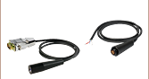
応力緩和ケーブル用コネクタ
メス型DB9コネクタ
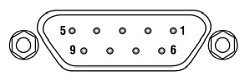
| DB9 Pina | Laser Pin Code (Click for Diagram) | |||||||
|---|---|---|---|---|---|---|---|---|
| A | B | C | D | E | F | G | H | |
| 1 | No Connection | |||||||
| 2 | - | - | PD Cathode | PD Cathode | - | - | - | - |
| 3 | LD Anode | LD Cathode | LD Cathode | LD Anode | LD Anode | LD Anode | LD Anode | LD Cathode |
| 4 | PD Anode | PD Anode | - | - | - | PD Anode | - | - |
| 5 | No Connection | |||||||
| 6 | No Connection | |||||||
| 7 | LD Cathode | - | - | LD Cathode | LD Cathode | LD Cathode | LD Cathode | - |
| 8 | - | LD Anode | LD Anode | - | - | - | - | LD Anode |
| 9 | No Connection | |||||||
変調入力
メス型SMAコネクタ
入力電圧: 0~2.5 V
入力インピーダンス: 1 MΩ
| Posted Comments: | |
Ishan Gunjal
(posted 2025-01-26 18:58:37.667) Hi. I wanted to enquire whether these and the TEC driver ICs are vacuum compatible. If so whether any extra heat dissipation mechanisms are required? jjadvani
(posted 2025-01-27 08:32:26.0) Dear Ishan, thank you for your inquiry. These TEC driver and evaluation board are made of PCB which will outgas in vacuum. So, these are not vacuum compatible. ChaeWon Kim
(posted 2023-12-01 14:15:32.7) Hello. I wonder if the MLDEVAL board and L980P010 diode are compatible. When I look at the website, it says they are compatible, but when I look at the board, I can't see the part where I can plug in the diode. Can I purchase and use another adapter in this case? Or can I just plug it in and use the laser? I'll wait for the answer. thank you. dpossin
(posted 2023-12-06 05:09:30.0) Dear Chae Won Kim,
Thank you for your inquiry. The MLDEVAL board alone is not feasible to drive laser diodes. You additionally need an suitable laser mount. For the L980P010 for example, the LDM56/M would work. I´ll reach out to you to discuss your application in more detail. user
(posted 2022-07-18 12:30:55.417) Are the formulas for the relation between laser diode current and setpoint control voltage correct on the page 8 in Data sheets of Laser Drivers MLD203CLN and MLD203CHB?
If setpoint control voltage is +2.5V, laser diode current would be 0.0002A (200uA ). dpossin
(posted 2022-07-19 04:45:13.0) Dear customer,
Thank you for your feedback. Yes you are right. The formula there is not entirely correct. Instead of 12500 ohms it should read 12.5 ohms of internal resistance. We try to correct this typo in the future. Sorry for the inconvenience! Peter Johnston
(posted 2022-04-14 13:37:38.027) The MLD203 datasheet is incorrect for the set current formula. It should be I_LD = V_SET/12.5, not 12500! Please update! mdiekmann
(posted 2022-04-22 02:47:31.0) Thank you very much for your feedback! We are looking into an update of the manual. Tony Pugatschew
(posted 2022-03-28 20:42:13.233) Dear Sir/
Modulation requirement at 2 Htz.
Data sheet does not specify the method?
Modulate Voltage rail ??
Any info apprecated.
Thanks
Tony Pugatschew dpossin
(posted 2022-04-01 09:23:32.0) Dear Tony,
Thank you for your feedback. I am reaching out to you in order to provide information how to correctly set up the MLD203CHB. Manuel B.
(posted 2020-09-23 22:05:28.4) The drivers works really great but the compliance voltage is really low. Is there any way to increase the voltage up to 5V by changing VIN2 or adding an offset voltage source? I want to use these drivers with the L405P20, PL450B and possibly L520P50, which all consume less than 200mA but the operating voltage is larger than 3V. Thanks nreusch
(posted 2020-09-25 06:27:38.0) Thank you for your feedback. The current models of our MLD series are not designed to provide up to 5 V. As there have been several inquiries from customers for higher compliance voltage MLDs, we will evaluate internally whether we would be able to offer such drivers in the future. They will, however, not be available on short time scales. I will contact you directly to check your requirements and time schedule in detail. In the meanwhile, you could probably use one of the other OEM or benchtop drivers like IP250-BV or LDC202C. 寛之 遠藤
(posted 2019-10-10 16:24:06.81) 現在、MLDEVALを用いてLDを駆動させようとしておりますが、LD出力が非常に急峻に変化してしまい、正常に動作させることができません。
こちらの製品について、正常に動作させるための技術的なサポートを受けることは可能でしょうか。ご回答をお待ちしております。 wskopalik
(posted 2019-10-10 05:29:21.0) This is a response from Wolfgang at Thorlabs. Thank you for your inquiry!
We will contact you regarding your issues with the MLDEVAL. Jan Soukup
(posted 2019-04-09 17:23:00.687) How can I drive a green laser diode that needs a 5.4 to 7 Volts operating voltage from MLDEVAL with MLD203P1E.
Thanks Jan swick
(posted 2019-04-18 04:18:19.0) This is a response from Sebastian at Thorlabs. Thank you for the inquiry. The MLD203P1E is designed for driving light sources in constant-power mode by regulating electrical current so that optical output power stays stable. The signal to which the driver regulates to needs to be generated by an optical sensor. An other point is that MLD203P1E works up to 200 mA and 3V which is is not suitable for LEDs with 5.4 to 7 V. I contacted you directly to provide further assistance. seungbum-yang
(posted 2018-10-18 23:54:32.023) I am using MLDEVAL evaluation board with MLD203P1.
most of the time it is OK. but sometimes, It feels like the laser is fluctuating periodically. the period is usually in few second scale, mostly about 4 sec.
I have checked this through checking correlation from laser speckle image.
Is there any reason that you know of regarding the laser fluctuation in period? swick
(posted 2018-11-02 04:52:49.0) This is a response from Sebastian at Thorlabs. Thank you for the inquiry.
The issue you are reporting sound like a drift which might be related to a non-stable temperature of the laserdiode.
This effect could be based on many parts within the setup.
I contacted you directly for troubleshooting. dreader
(posted 2018-06-07 08:46:48.657) Hi, the comments in your feedback section suggest that some customization may be possible to achieve a higher compliance voltage. If so, can you tell me more about it? mvonsivers
(posted 2018-06-12 06:30:40.0) This is a response from Moritz at Thorlabs. Thank you for your inquiry and the interest in our products. I will contact you directly to discuss our options for customization. eileenscannelll
(posted 2018-05-27 21:26:54.873) Query re diode laser removal systems mvonsivers
(posted 2018-06-01 04:13:58.0) This is a response from Moritz at Thorlabs. Thank you for your inquiry. I will contact you directly to further discuss your application. chaowenliang
(posted 2017-10-16 03:45:53.0) The MLD 3V compliance Voltage is too low for the Blue and UV diode. If you can raise it up to 8v, what's the maximum current available? swick
(posted 2017-10-20 03:49:33.0) This is a response from Sebastian at Thorlabs. Thank you for the inquiry. We do not offer MLDs with compliance voltage of 8V. Alternatively you can use LDC202C, LDC205C or LDC210C which have compliance voltage of 10V. ludoangot
(posted 2017-04-18 16:32:11.083) Would it be possible you consider making such a driver with the same efficient design and ease of use but with higher maximum current and compliance voltage? swick
(posted 2017-04-19 03:11:04.0) This is a response from Sebastian at Thorlabs. Thank you for the feedback. We can modify our MLD modules for custom applications with different current and voltages ranges.
I will contact you directly to discuss further details. ludoangot
(posted 2016-09-23 12:14:49.8) Hello, can the drivers be used in a parallel configuration to increase the output current? And how does the circuit behaves when the compliance voltage is reached and exceeded? swick
(posted 2016-09-27 10:14:16.0) This is a response from Sebastian at Thorlabs. Thank you very much for your questions. The Constant Current Laser Drivers (MLD203CLN and MLD203CHB) can be paralleled to increase output current.
For optimal load sharing an additional load resistor can be added.
When the compliance voltage is exceeded the maximum output current will decrease. cbrideau
(posted 2016-09-14 16:33:47.54) What enclosure does the MLDEVAL fit in? swick
(posted 2016-09-15 05:41:39.0) This is a response from Sebastian at Thorlabs. Thank you very much for your feedback.
We have developed this evaluation board to offer a multifunctional tool to test products of our MLD Series before a PCB has to be designed for integrating our modules into specific applications.
Therefore the MLDEVAL is made for evaluation purposes. It provides rubber feet to ensure stable stand on a laboratory table without the need of extra housing.
For OEM customers we can offer customized application boards, which fits perfectly to customized housings. mitch
(posted 2016-08-28 07:02:00.877) Hi, this new product look extremely useful - thanks! I would like to use the constant power version with my own custom bias-T for analog modulation. Is this device compatible if I were to connect a bias-t (perhaps your one) between the LD and the GND_LD or LDA pin? I prefer to use type A laser diodes. Thanks swick
(posted 2016-08-29 04:32:32.0) This is a response from Sebastian at Thorlabs. Thank you very much for your inquiry.
Using a Bias-T with our Constant Power LD Driver (MLD203P1) will not work, because it would disturb the internal regulation of the output power. Modulation of MLD203P1 can be done by modulating P-Set(input) with approx. 1-50 kHz.
With our Constant Current Drivers (MLD203CHB and MLD203CLN) it will work to use a Bias-T for modulation.
I will contact you directly to discuss your application in more detail. ludoangot
(posted 2016-08-25 12:00:59.203) Is there any limitation to using these to drive LED (providing the LED complies with the driver's specs)? Also, I totally second the previous comment. A blank or pre-soldered PCB for fast prototyping with these drivers would be very welcome. Ideally with the option to plug said PCB into common breadboards (0.1 in pitch). swick
(posted 2016-08-25 03:11:58.0) This is a response from Sebastian at Thorlabs. Thank you very much for your inquiry.
It will work to drive LEDs with MLD203CHB or MLD203CLN if all important parameters of the LEDs are due to the controller's specification. Most limiting factor for driving LEDs with MLDCxx modules will be the compliance voltage, which is typical 3 V.
Regarding the PCB for fast prototyping, we will release an evaluation board during next weeks. Together with the evaluation board we will release the requested adapter plug with 0.1 in pitch pin headers for direct use in breadboards. cbrideau
(posted 2016-08-17 14:14:42.88) A version of these pre-soldered on a break-out PCB with protoboard tinned holes sized to fit into one of the EEB enclosures would be very helpful for DIY assembly. swick
(posted 2016-08-18 08:42:45.0) This is a response from Sebastian at Thorlabs. Thank you very much for your feedback. We will look into this, discuss your suggestion internally and contact you directly by email. |
、組み込み用途向け")
 ズーム
ズーム
Click for Details
大量注文はアセンブリへの組み込みが簡単になるようICチューブでのお届けも可能です。
- 定電流半導体レーザ(LD)ドライバ、すべてのピンコード向け(A~H)
- MLD203CHB: 高帯域変調(3 dBで最大100 kHz)用に最適化
- MLD203CLN: 低電流ノイズ(3 µA、RMS値)用に最適化
- 定光出力半導体レーザ(LD)ドライバモデル
- MLD203P1: ピンコードA、B、F
- MLD203P2: ピンコードC、D
こちらのドライバは、大量発注による割引が可能です。数量ごとの単価は、下の定価欄の「Volume Pricing」のリンクをクリックするとご覧いただけます。
評価ボードMLDEVALのソケットに対応するドライバは下記にてご紹介しています。
半導体レーザのピンコード

 ズーム
ズーム
Click for Details
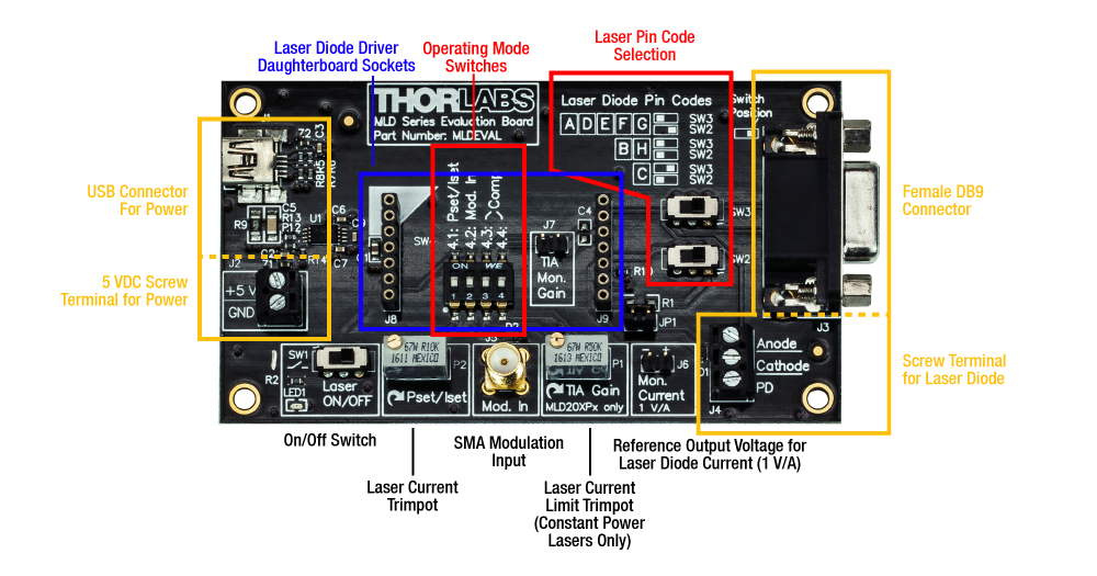
評価ボードMLDEVALのトップビューとその機能要素

Click to Enlarge
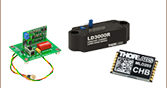
ドライバMLD203CHBEを搭載した評価ボード
- 試験用評価ボードと組み込み用半導体レーザードライバ
- 半導体レーザ用メス型DB9コネクタとネジターミナル
- 5 VDC電源用USBコネクタとネジターミナル
- 半導体レーザの動作設定を行うトリムポット
- 変調信号入力用SMAコネクタ
- 評価ボードに取り付けられるよう設計された半導体レーザードライバ
評価ボード
評価ボードMLDEVALは一般的なコネクタ数個で当社の組み込み用半導体レーザードライバに接続するブレイクアウトボードです。ストレインリリーフケーブルに接続された半導体レーザ用のメス型DB9コネクタや、TO -Can型半導体レーザを直接ワイヤでつなぐためのネジターミナルが付いています。5 VDCの電源はUSBまたはネジターミナルを介して供給されます。
2つのトリムポットで半導体レーザの動作設定を行います。Pset/Isetのトリムポットでレーザ電流を0 mA~200 mAの間で調整します。定電流ならびに定光出力のどちらのドライバにも使用できます。TIAゲイントリムポットではモニタ用ダイオードの電流制限値を設定します。よって定電流ドライバにのみに使用します。レーザの光出力をリモートにより変調する場合には、メス型のSMAコネクタより電圧を印加します(動作パラメータについては「仕様」のタブをご覧ください)。
基板の寸法は105.8 mm × 56.0 mm × 14.1 mmで、メス型DB9コネクタを含みます。四隅にあるØ3.2 mmの4つの貫通穴はカスタムでの取り付け用です。
評価ボードで使用する半導体レーザードライバ
当社の組み込み用半導体レーザードライバにはメッキ加工のハーフホールコネクタが付いています。これはドライバが自動アセンブリシステムで取り付けられることを想定しています。各ドライバは評価ボードMLDEVALに簡単に取り付けられるように、予めドーターボードに取り付けられた状態でご購入いただけます。このドーターボードは、ソケットに合わせて挿入することで評価ボードに取り付けられるため、研究室やテスト環境ですぐにドライバが使用可能となります。
ドライバを取り付ける前に、ドライバやレーザのピンコードにより評価ボードのいくつかのスイッチを正しい位置に設定する必要があります。スイッチの位置の詳細については、評価ボードマニュアルの4と5をご覧ください。いくつかのスイッチはドライバの選択後には変更できませんし、ドライバを取り付けている間はスイッチにアクセスできません。