 Products Home / 半導体レーザ用電流コントローラ(LDドライバ)、温度コントローラ、LDマウント / 電流コントローラと温度コントローラ一体型ドライバ / QCL用高出力電流/TECコントローラ
QCL用高出力電流/TECコントローラ
- High Compliance Voltages Designed to Support QCL Lasers
- Drive Currents up to 2 A or 5 A
- Provides TEC Currents up to ±15 A
- 0.002 °C Temperature Stability Over 24 hrs
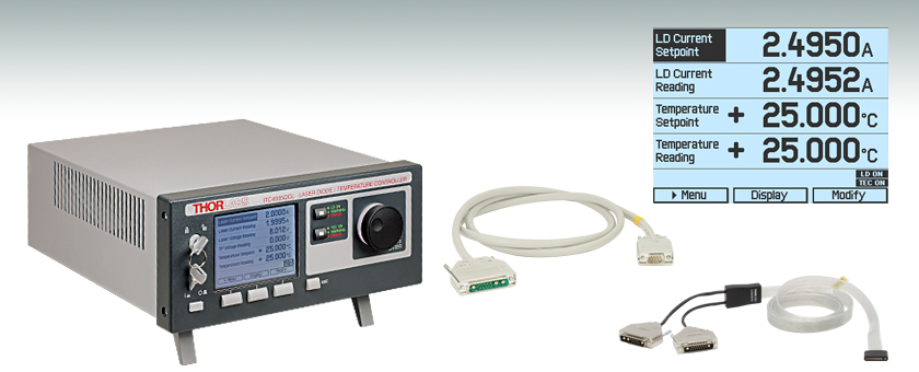
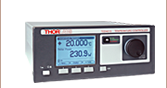
ITC4005QCL
Designed for Driving QCLs
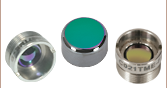
CAB4007B
Laser Diode /TEC Cable
for HHL Packages
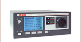
The main measurement display
shows readout values and device
status information.
CAB4005
Laser Diode Cable


Please Wait
特長
- 高いコンプライアンス電圧で高出力な量子カスケードレーザ(QCL)を駆動
- ITC4002QCL:17 V
- ITC4005QCL:20 V
- ≤2 A(ITC4002QCL)または≤5 A (ITC4005QCL)の駆動電流でレーザを駆動
- 連続発振(CW)または準連続発振(QCW)動作
- LEDも駆動可能
- アクティブ電源管理による高効率動作
- 優れた温度安定性:0.002°C(24 時間)
- デジタルPID制御ではP、I、Dを別々に設定可
- 自動PIDチューニング機能
- 調整可能な温度センサーオフセット
- 半導体レーザ/TECコントローラ用コネクターケーブルも別途ご用意
- 高熱負荷(HHL)レーザ向け半導体レーザ/TECコントローラ用コネクターケーブル(型番CAB4007AとCAB4007B)
- 標準的な半導体レーザ用ケーブル (型番CAB4005))
- 標準的なTECコントローラ用ケーブル(型番CAB4000)および高電流ケーブル(型番CAB4001)
| Item #a | ITC4002QCL | ITC4005QCL |
|---|---|---|
| Current Control Range | 0 to 2 A | 0 to 5 A |
| Compliance Voltage | 17 V | 20 V |
| Photocurrent Measurement Ranges | 2 mA / 20 mA | |
| QCWb Mode Pulse Width Range | 100 µs to 1 s | |
| QCWc Repetition Rate Range | 1 ms to 5 s (0.2 to 1000 Hz) | |
| TEC Current Range | -15 to +15 Ad | |
| TEC Compliance Voltage | >15 V | |
| TEC Output Power (Max) | >225 W | |
| Temperature Range (Max) | -150 to +150 °Cc | |
| Supported Temperature Sensors | Thermistors (TH10K), Pt100 (TH100PT), Pt1000, AD590, AD592, LM335, LM235, LM135, LM35 | |
当社の半導体レーザ電流/TECコントローラは、17 V(ITC4002QCL)または20 V(ITC4005QCL)の高いコンプライアンス電圧により、高出力量子カスケードレーザ(QCL)を駆動します。電流コントローラLDC4000シリーズと温度コントローラTED4015の機能を組み込んだ複合装置です。ITC4002QCLならびにITC4005QCLは、最大2 Aまたは5 Aの駆動電流で半導体レーザに精密かつ安定的に電流を供給します。 どちらも24時間で0.002 °C以内の優れた温度安定性があります。 適切なノイズ性能を得るためには、コントローラの最大定格電圧、電流がレーザを動作させるために必要な電圧、電流に最も近く、かつ超えているコントローラをお選びください。
このコントローラは全ての半導体レーザとモニタ用ダイオードのピン配置、ならびに当社の2タブ付きCマウントQCLまたはICLパッケージに対応します。定電流(CC)または定光出力(CP)モードがあるのが特長です。一般的な温度センサはほとんどご使用いただけます。デジタルPIDコントローラにより異なる熱負荷にも適応可能です。PIDコントローラは内蔵のPID自動設定機能、またはP、I、Dのパラメータをそれぞれ設定することによって操作できます。詳細については「追加情報」タブをご覧ください。
ITC4002QCLならびにITC4005QCLは、前面パネルキーならびに大型で読み取りが簡単なグラフィックLCDディスプレイ上の操作メニューから制御します(サンプルをご覧になりたい方は「画面表示」タブをご覧ください)。またこれらのコントローラは、SCPI準拠のUSBインターフェイスによっても制御ができます。より高度な設定や高い測定分解能設定はUSB操作でご提供しています。前面パネルの分解能は、画面の解像度ならびにリフレッシュレートによって制限されてしまうからです。また、様々な出力端子やデジタルI/Oポートが付いており、多くの制御や機器接続が可能です。内蔵のファンクションジェネレータにより、レーザ出力のアナログ変調も簡単にできます。
その他にも、準連続発振(QCW)動作モード、簡単なPID自動設定、半導体レーザならびにTEC素子の多様な保護機能など、高度な機能が多数備わっております(詳細については「追加情報」タブをご覧ください)。また、静かで電源効率の良い動作が可能な設計となっております。以上の機能により、ITC4002QCLならびにITC4005QCLは、中~高出力のQCL、ICL、半導体レーザを研究現場や製造環境において安全かつ確実に動作する用途に適しています。当社ではこれらのコントローラを24か月ごとに校正することをお勧めしております。当社では再校正サービスを提供しております。詳細は当社までお問い合わせください。
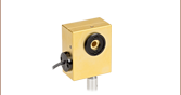
当社では半導体レーザ/TECコントローラ間で安全で信頼性の高い接続が可能なコネクターケーブルをご用意しております。半導体レーザ/TECコントローラ用コネクターケーブルCAB4007AおよびCAB4007Bは高熱負荷(HHL)パッケージ用に設計されています。CAB4007AはコントローラとHHLレーザ用液体冷却式マウントLCM100/Mの接続に特化したケーブルです。CAB4007Bは、標準的な10ピンHHLパッケージを当社のコントローラITC400xQCLに接続するためのケーブルです。LD接続用ケーブルCAB4005とTEC接続用ケーブルCAB4000は、標準的な5Aのコネクターケーブルで、ITC4002QCLとITC4005QCLに付属しています。TEC接続用ケーブルCAB4001は、20 Aまでの高電流ケーブルです。
当社ではコンプライアンス電圧が11 Vまたは12 Vの半導体レーザ駆動電流/TECコントローラもご用意しております。
ドライバーソフトウェア、ならびにSCPI、LabVIEW™、Visual C++、Visual C#、Visual Basicのプログラミングリファレンスガイドについては「ソフトウェア」のタブをご覧ください。
半導体レーザ動作モード
半導体レーザは、お客様が設定するレベルでレーザ電流を精密に保つ定電流(CC)モード、あるいは光パワーセンサを使って、レーザ出力パワーをモニタし、アクティブな一定出力制御を行う定出力(CP)モードで駆動できます。 低ノイズ、高応答速度が要求される場合にはCCモードの方が望ましいですが、このモードでは一般的に温度の安定化も必要となります。 CPモードでは、ほとんどのレーザーパッケージに内蔵されている内部フォトダイオードまたは外部フォトダイオードによるフィードバックを利用して、レーザの出力パワーをアクティブに安定化します。
20 Aピークの100 µsパルス
図:ITC4020をQCWモードで動作時、電流20 A、幅100 µsの短パルスを示したオシロスコープのスクリーンショット
ITC4002QCLならびにITC4005QCLには、モニタ用の入力端子が2つあります。1つはフォトダイオード用で、もう1つはサーモパイル用です。いずれかを半導体レーザの制御にお選びいただけます。 外部入力、または内蔵のファンクションジェネレータを介したアナログ変調で、CCモードならびにCPモードの半導体レーザに変調をかけることができます。 レーザ駆動電流に比例する信号電圧がモニタ用に出力されます。
パルス動作
半導体レーザードライバのITC4000シリーズは、用途によって連続発振(CW)または準連続発振(QCW)モードで動作させることができます。 右図は、コントローラの性能を示すオシロスコープのスクリーンショットです。QCWモードで動作中の電流/TECコントローラITC4020の出力電流がオシロスコープで測定されています。 ITC4020は、ピーク電流20 Aでシャープかつ正確な100 µsパルスをオーバーシュート無しで生成します。 ITC4002QCLならびにITC4005QCLは、それぞれの電流範囲で同様の性能を発揮します。 内蔵されているパルスジェネレータは、調節可能な繰り返し周波数による内部トリガか、ユニットの背面のBNCジャックから介する外部トリガによって開始されます。
半導体レーザ保護特性
電流リミット値: レーザ電流が最大値を超えないよう、電流リミット値を精密に設定することができます。 また誤調整を防ぐため、この機能へ簡単にアクセスできないように設計されています。 あらかじめ設定された値を超えてレーザ駆動電流を増加させようとすると、表示と短い警告音が発せられます。 外部変調機能を使用する際にも電流リミット値を超えた電流供給はできません。
電流電源:電流電源とレーザの接続が遮断された場合、電流電源のスイッチは自動的にOFFになります。 開回路状態は、コントローラ上の「OPEN」の表示と短い警告音で知らされます。 レーザ電流は、独立したレーザONキーによってONとOFFに切り替えます。 スイッチをOFFにするとデバイス内の電子スイッチが半導体レーザを短絡させ、保護します。 スイッチをONにするとソフトスタートによって過電圧することなくレーザ電流がゆっくりと増加します。 ラインに故障が生じてもレーザ電流は過渡的な影響を受けません。 AC電源からの過電圧は、内蔵の電気フィルタ、トランスの遮断機構により抑えられ、さらに筐体をしっかりアースすることによって効果的に抑制されます。
TECコントローラ
電流/TECコントローラITC4002QCLならびにITC4005QCLには高性能のデジタルTECコントローラが内蔵されており、最大±15 Aの電流を出力します。24時間で0.002 °Cの優れた温度安定性とTECコントローラTED4015と同様の保護機能と操作機能を備えています。 デジタルPIDコントローラは、個々に調節可能なパラメータ、あるいは自動PID調整機能(詳細については、TECコントローラTED4015の製品ページをご覧ください)によって、様々な熱負荷を適用できます。 温度センサ入力部の最大制御範囲は、サーミスタの場合100 Ω~1 MΩ、温度センサICや白金RTDセンサの場合-55~150 °Cです。 実際の温度範囲は、接続したセンサや温度設定によって制限されます。 TEC素子を最大限に保護するために ITCシリーズはTECコントローラTED4015と同等の機能を備えています。 保護機能には、調節可能なTEC出力電流リミット値ならびに温度センサ誤動作警報が含まれます。
これらのコントローラは、実際の温度と設定温度の差に比例したモニタ信号を供給します。 背面パネルのBNCコネクタにオシロスコープまたはアナログデータ取得デバイスを接続し、異なる熱負荷に対する温度収束特性をモニタすることができます。
レーザ電流コントローラ
| Item # | ITC4002QCL | ITC4005QCL | ||
|---|---|---|---|---|
| Front Panela | Remote Controla | Front Panela | Remote Controla | |
| Current Control (Constant Current Mode) | ||||
| Laser Diode Current Range | 0 to 2 A | 0 to 5 A | ||
| Compliance Voltage | 17 V | 20 V | ||
| Setting / Measurement Resolution | 100 µA | 32 µA | 1 mA | 80 µA |
| Accuracy | ±(0.1% + 800 µA) | ±(0.1% + 2 mA) | ||
| Noise and Ripple (10 Hz to 10 MHz, rms, Typical, w/o Noise Reduction Filter) | <20 µA | <250 µA | ||
| Noise and Ripple (10 Hz to 10 MHz, rms, Typical, w/ Noise Reduction Filter) | <5 µA | <50 µA | ||
| Drift, 24 Hours (0-10 Hz, Typical, at Constant Ambient Temperature) | <150 µA | <300 µA | ||
| Temperature Coefficient | ≤50 ppm/°C | |||
| Current Limit | ||||
| Setting Range | 2 mA to 2 A | 5 mA to 5 A | ||
| Setting Resolution | 100 µA | 32 µA | 1 mA | 80 µA |
| Accuracy | ±(0.12% + 1.6 mA) | ±(0.12% + 3 mA) | ||
| Power Monitor Input - Photodiode | ||||
| Photocurrent Measurement Ranges | 0 to 2 mA / 0 to 20 mA | |||
| Photocurrent Measurement Resolution (2 mA Range / 20 mA Range) | 1 µA / 10 µA | 32 nA / 320 nA | 1 µA / 10 µA | 32 nA / 320 nA |
| Photocurrent Accuracy (2 mA Range / 20 mA Range) | ±(0.08% + 0.5 µA) / ±(0.08% + 5 µA) | |||
| Photodiode Reverse Bias Voltage | 0 to 10 V | |||
| Photodiode Input Impedance | ~0 Ω (Virtual Ground) | |||
| Power Monitor Input - Thermopileb | ||||
| Voltage Measurement Ranges | 0 to 10 mV / 0 to 100 mV / 0 to 1 V / 0 to10 V | |||
| Voltage Measurement Resolution (for 10 mV / 100 mV / 1 V / 10 V Range) | 1 µV / 10 µV / 100 µV / 1 mV | 0.16 µV / 1.6 µV / 16 µV / 160 µV | 1 µV / 10 µV / 100 µV / 1 mV | 0.16 µV / 1.6 µV / 16 µV / 160 µV |
| Voltage Measurement Accuracy (for 10 mV / 100 mV / 1V / 10 V Range) | ±(0.1% + 10 µV) / ±(0.1% + 100 µV) / ±(0.1% + 1 mV) / ±(0.1% + 5 mV) | |||
| Voltage Input Impedance | 1 MΩ | |||
| Laser Power Control (Constant Power Mode) | ||||
| Photocurrent Control Rangesc | 0 to 2 mA / 0 to 20 mA | |||
| Photocurrent Setting Resolution | 1 µA / 10 µA | 32 nA / 320 nA | 1 µA / 10 µA | 32 nA / 320 nA |
| Thermopile Voltage Control Rangesc | 1 µV to 10 mV / 10 µV to 100 mV / 100 µV to 1 V / 1 mV to 10 V | |||
| Thermopile Voltage Setting Resolution | 1 µV / 10 µV / 100 µV / 1 mV | 0.16 µV / 1.6 µV / 16 µV / 160 µV | 1 µV / 10 µV 100 µV / 1 mV | 0.16 µV / 1.6 µV / 16 µV / 160 µV |
| Power Limit (Constant Power Mode) | ||||
| Photocurrent Limit Setting Rangesc | 5 µA to 2 mA / 50 µA to 20 mA | |||
| Photocurrent Limit Resolution (2 mA Range/ 20 mA Range) | 1 µA / 10 µA | 128 nA / 1.28 µA | 1 µA / 10 µA | 128 nA / 1.28 µA |
| Photocurrent Limit Accuracy | ±20 µA / ±200 µA | |||
| Thermopile Voltage Limit Setting Rangesc | 1 µV to 10 mV / 10 µV to 100 mV / 100 µV to 1V / 1 mV to 10V | |||
| Thermopile Voltage Limit Resolution | 1 µV / 10 µV / 100 µV / 1 mV | 730 nV / 7.3 µV / 73 µV / 730 µV | 1 µV / 10 µV 100 µV / 1 mV | 730 nV / 7.3 µV 73 µV / 730 µV |
| Thermopile Voltage Limit Accuracy | ±10 µV / ±100 µV / ±1 mV / ±10 mV | |||
| Front Panela | Remote Controla | Front Panela | Remote Controla | |
| Laser Voltage Measurement | ||||
| Measurement Principle | 4-Wire | |||
| Measurement Resolution | 1 mV | 320 µV | 1 mV | 320 µV |
| Accuracy | ±30 mV | |||
| Laser Overvoltage Protection | ||||
| Setting Range | 1 V to 17 V | 1 V to 20 V | ||
| Resolution | 1 mV | |||
| Accuracy | ±70 mV | |||
| Laser Current Monitor Output | ||||
| Load Resistance | >10 kΩ | |||
| Transmission Coefficient | 5 V/A ± 5% | 2 V/A ± 5% | ||
| External Modulation Input | ||||
| Input Impedance | 10 kΩ | |||
| Small Signal 3dB Bandwidth, CC Mode w/o Noise Reduction Filter | DC to 130 kHz (2 Ω Load) | DC to 100 kHz (1 Ω Load) DC to 50 kHz (5 Ω Load) | ||
| Small Signal 3dB Bandwidth, CC Mode w/ Noise Reduction Filter | DC to 10 kHz (2 Ω Load) | DC to 6 kHz (1 Ω Load) DC to 5 kHz (5 Ω Load) | ||
| Modulation Coefficient, CC Mode | 200 mA/V ± 5% | 500 mA/V ± 5% | ||
| Modulation Coefficient, CP Mode, Current Sensorc | 200 µA/V / 2 mA/V ± 5% | |||
| Modulation Coefficient, CP Mode, Voltage Sensorc | 1 mV/V / 10 mV/V / 100 mV/V / 1 V/V ± 5% | |||
| Internal Laser Modulation | ||||
| Waveforms | Sine, Square, Triangle | |||
| Frequency Range | 20 Hz to 130 kHz | 20 Hz to 100 kHz | ||
| Modulation Depth | 0.1 to 100% | |||
| QCW Mode | ||||
| Pulse Width Range | 100 µs to 1 s | |||
| Pulse Width Resolution | 1 µs | |||
| Repetition Rate Range | 1 ms to 5 s (0.2 to 1000 Hz) | |||
| Repetition Rate Resolution | 10 µs | |||
| Trigger | ||||
| Input | Rising Edge Triggered, Starts QCW Pulse with Internal Adjusted Width | |||
| Input Level | TTL or 5 V CMOS | |||
| Output | Active High, Tracks Pulse Width | |||
| Output Level | TTL or 5 V CMOS | |||
| Death Time to Next Pulse | >10 µs | |||
温度制御
| Item # | ITC4002QCL | ITC4005QCL | ||
|---|---|---|---|---|
| Front Panela | Remote Controla | Front Panela | Remote Controla | |
| TEC Current Control | ||||
| Control Range | -15 to +15 A | |||
| Compliance Voltage | >15 V | |||
| Maximum Output Power | >225 W | |||
| Resolution, CC Mode | 1 mA | 0.1 mA | 1 mA | 0.1 mA |
| Accuracy | ± (0.2% + 20 mA) | |||
| Noise and Ripple (Typical) | <10 mA rms | |||
| TEC Current Limit | ||||
| Setting Range | 0.1 A to 15 Ab | |||
| Resolution | 1 mA | 0.1 mA | 1 mA | 0.1 mA |
| Accuracy | ± (0.2% + 10 mA) | |||
| NTC Thermistor Sensors | ||||
| Resistance Measurement Ranges | 100 Ω to 100 kΩ / 1 kΩ to 1 MΩ | |||
| Control Range Maxc | -150 to +150 °C | |||
| Temperature Resolution | 0.001 °C | |||
| Resolution (Resistance, 100 kΩ/1 MΩ Range) | 0.1 Ω / 1 Ω | 0.03 Ω / 0.3 Ω | 0.1 Ω / 1 Ω | 0.03 Ω / 0.3 Ω |
| Accuracy (100 kΩ/1 MΩ Range) | ± (0.06% + 1 Ω / 5 Ω) | |||
| Temperature Stability (24 hours typ.)c | <0.002 °C | |||
| Temperture Coefficient | <5 mK/°C | |||
| IC Sensors | ||||
| Supported Current Temperature Sensors | AD590, AD592 | |||
| Supported Voltage Temperature Sensors | LM335, LM235, LM135, LM35 | |||
| Control Range with AD590 | -55 to +150 °C | |||
| Control Range with AD592 | -25 to +105 °C | |||
| Control Range with LM335 | -40 to +100 °C | |||
| Control Range with LM235 | -40 to +125 °C | |||
| Control Range with LM135 | -55 to +150 °C | |||
| Control Range with LM35 | -55 to +150 °C | |||
| Resolution | 0.001 °C | 0.0001 °C | 0.001 °C | 0.0001 °C |
| Accuracy AD590 Current | ± (0.04% + 0.08 µA) | |||
| Accuracy LM335/LM35 Voltage | ± (0.03% + 1.5 mV) | |||
| Temperature Stability (24 hours) | <0.002 °C | |||
| Temperature Coefficient | <5 mK/°C | |||
| Front Panela | Remote Controla | Front Panela | Remote Controla | |
| Pt100/Pt1000 RTD Sensors | ||||
| Temperature Control Range | -55 to +150 °C | |||
| Resolution | 0.001 °C | 0.0003 °C | 0.001 °C | 0.0003 °C |
| Accuracy (4-Wire Measurement) | ±0.3 °C | |||
| Temperature Stability (24 hours) | <0.005 °C | |||
| Temperature Coefficient | <20 mK/°C | |||
| Temperature Window Protection | ||||
| Setting Range Twin | 0.01 to 100.0 °C | |||
| Protection Reset Delay | 0 to 600 s | |||
| Window Protection Output | TTL or 5 V CMOS | |||
| Temperature Control Output | ||||
| Load Resistance | >10 k Ω | |||
| Transmission Coefficient | ΔT * 5V / Twin ±0.2 % (Temperature Deviation, Scaled to Temperature Window) | |||
| TEC Voltage Measurement | ||||
| Measurement Principle | 4-Wire/2-Wire | |||
| Resolution | 100 mV | 40 mV | 100 mV | 40 mV |
| Accuracy (with 4-Wire Measurement) | ±50 mV | |||
一般的な仕様
| Item # | ITC4002QCL | ITC4005QCL |
|---|---|---|
| Digital I/O Port | ||
| Number of I/O lines | 4 (Separately Configurable) | |
| Input Level | TTL or CMOS, Voltage Tolerant up to 24 V | |
| Output Level (Source Operation) | TTL or 5 V CMOS, 2 mA Max | |
| Output Level (Sink Operation) | Open Collector, up to 24 V, 400 mA Max | |
| Interface | ||
| USB 2.0 | According to USBTMC/USBTMC-USB488 Specification Rev. 1.0 | |
| Protocol | SCPI Compliant Command Set | |
| Drivers | VISA VXIpnp™, MS Visual Studio™, MS Visual Studio.net™, NI LabVIEW™, NI LabWindows/CVI™ | |
| General Data | ||
| Safety Features | Interlock, Inhibit, Keylock Switch, Laser Current Limit, Laser Power Limit, Soft Start, Short Circuit when Laser off, Adjustable Laser Overvoltage Protection, Over Temperature Protection Temperature Window Protection | |
| Display | LCD 320 x 240 Pixel | |
| Connector for Laser, Photodiode, Interlock, and Laser On Signal | 13W3 Mixed D-Sub Jack (Female) | |
| Connector for Sensor, TE Cooler, TEC On Signal | 17W2 Mixed D-Sub Jack (Female) | |
| Connectors for Control Input / Output | BNC | |
| Connector for Digital I/O | Mini DIN 6 | |
| Connector for USB-Interface | USB Type B | |
| Chassis Ground Connector | 4 mm Banana Jack | |
| Line Voltage / Frequency | 100 to 120 V and 200 to 240 V ±10%, 50 to 60 Hz | |
| Maximum Power Consumption | 600 VA | 880 VA |
| Mains Supply Overvoltage | Category II (Cat II) | |
| Operating Temperature | 0 to 40 °C | |
| Storage Temperature | - 40 to +70 °C | |
| Relative Humidity | Max 80% Up to 31 °C, Decreasing to 50% at 40 °C | |
| Pollution Degree (Indoor Use Only) | 2 | |
| Operation Altitude | <2000 m | |
| Warm-up Time for Rated Accuracy | 30 min | |
| Weight | 6.4 kg | |
| Dimensions without Operating Elements (W x H x D) | 263 mm x 122 mm x 307 mm (10.4" x 4.8" x 12.1") | |
| Dimensions with Operating Elements (W x H x D) | 263 mm x 122 mm x 345 mm (10.4" x 4.8" x 13.6") | |
全ての技術データは、温度23±5°C、相対湿度45±15%の条件下で有効です。 なお、予告なしに変更される場合があります。
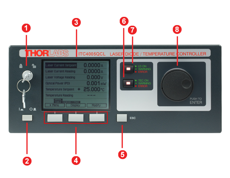
ITC4000シリーズの前面パネル
| Callout | Connection | Callout | Connection |
|---|---|---|---|
| 1 | Key Switch | 5 | Escape Key |
| 2 | Supply Power Switch | 6 | TEC Status Indicator |
| 3 | LC Display | 7 | LD Status Indicator |
| 4 | Softkeys for Menu Navigation | 8 | Adjustment Knob |
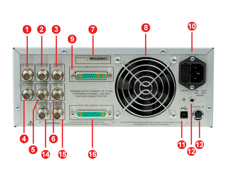
ITC4000シリーズの背面パネル
| Callout | Connection | Callout | Connection |
|---|---|---|---|
| 1 | TTL Input "Laser Enable In" 5 V Max | 9 | LD Output and Optical Sensor Input "Laser Output" |
| 2 | TTL Input "QCW Pulse In" 5 V Max | 10 | Power Connector and Fuse Holder "Line In" |
| 3 | TTL Output "Trigger Out" 0 - 5 V | 11 | USB Connector |
| 4 | Optical Sensor Input "Opt Sensor In" 0 to 10 V Max | 12 | 4 mm Banana Jack for Chassis Ground |
| 5 | Modulation input "Modulation In" -10 to 10 V | 13 | MiniDin-6 Jack "Digital I/O" |
| 6 | Laser Current Monitor "Analog CTL Out" 0 - 10 V | 14 | Actual Temperature Deviation Output "Deviation Out" -5 to 5 V |
| 7 | Serial Number of the Unit | 15 | TTL Temperature Monitor Output "Temp OK Out" 5 V |
| 8 | Cooling Fan | 16 | TEC Element Output and Temperature Sensor Input "TEC Output" |
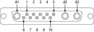
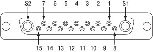
半導体レーザ出力端子
13W3 Mixed D-Subジャック
| Pin | Connection | Pin | Connection |
|---|---|---|---|
| 1 | (Thermo) Voltage Sensor Input (+) | 7 | Photo Current Sensor Input (+) |
| 2 | (Thermo) Voltage Sensor Ground (-) | 8 | Photo Current Sensor Ground (-) |
| 3 | Not Connected | 9 | Not Connected |
| 4 | Laser Diode Anode (+) | 10 | Laser Diode Cathode (-) |
| 5 | Output for Interlock and Status Indicator "LASER ON/OFF" (+) | A1 | Laser Diode Ground |
| 6 | Ground Pin for Interlock and Status Indicator "LASER ON/OFF" (-) | A2 | Laser Diode Cathode (with Polarity AG) (-) |
| A3 | Laser Diode Anode (with Polarity CG) (+) |
TEC出力端子
17W2 Mixed D-Subジャック
| Pin | Connection | Pin | Connection |
|---|---|---|---|
| 1 | Interlock, TEC ON LED (+) | 10 | PT100/1000 (-), AD590/592 (-), LM35 Out, LM135/235/335 (+) |
| 2 | Voltage Measurement TEC Element (+) | 11 | PT100/1000 (+), AD590/592 (+), LM35/135/235/335 (+) |
| 3 | Thermistor (-), PT100/1000 (-), Analog Ground | 12 | Analog Ground, LM35/135/235/335 (-) |
| 4 | Thermistor (+), PT100/1000 (+) | 13 | Not Connected |
| 5 | Analog Ground, LM35/135/235/335 (-) | 14 | I/O 1-wire (Currently Not Used) |
| 6 | Digital Ground for I/O 1-wire | 15 | Ground for 12 V Output and Interlock, TEC ON LED (-) |
| 7 | 12 V Output (for External Fan, max. current = 500 mA) | S1 | TEC Element (+) (Peltier Element) |
| 8 | Not Connected | S2 | TEC Element (-) (Peltier Element) |
| 9 | Voltage Measurement TEC Element (-) |
デジタル I/Oポート
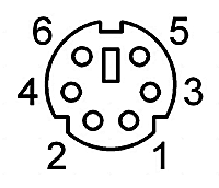
| Pin | Connection |
|---|---|
| 1 | I/O 1 |
| 2 | I/O 2 |
| 3 | I/O 3 |
| 4 | I/O 4 |
| 5 | GND |
| 6 | I/O Supply Voltage (+12 V from internal or higher external voltage up to +24 V) |
LD Enable入力端子
BNCメス型
レーザをEnableにする信号入力(HighでレーザON)、TTL 5 V max
準連続発振(QCW)パルス入力端子
BNCメス型
外部トリガ信号入力、TTL 5 V max
トリガ出力端子
BNCメス型
準連続発振(QCW)パルストラッキング出力端子、TTL 5 V
光学センサ入力端子
BNCメス型
光学センサ用入力、0~+10 V
変調入力端子
BNCメス型
外部変調信号用入力、 -10~+10 V
アナログCTL出力端子
BNCメス型
レーザ電流モニタ用出力、0~+10 V
温度差分出力端子
BNCメス型
実際の温度差分出力、 -5~+5 V
温度OK出力端子
BNCメス型
温度OK信号出力(指定温度範囲内であればHigh)、TTL 5 V
PC接続用
USB B型
USBのB型-A型変換ケーブルが付属します。
グラウンド
シャーシグラウンド用4 mmバナナジャック
半導体レーザ/TECケーブルCAB4007A
このケーブルは柔軟性の高いフラットケーブルで構成されており、片端には9W4オス型コネクタ、もう一方には17W2および13W3オス型コネクタが付いています。CAB4007Aは液体冷却式マウントLCM100/Mと当社のITC400xQCLシリーズコントローラの接続にご使用いただけます。

17W2オス型コネクタ
13W3オス型コネクタ
9W4オス型コネクタ
| CAB4007A | ||||
|---|---|---|---|---|
| 9W4 Pin | Signal | 13W3 Pin | 17W2 Pin | Max Current Input |
| A4 | TEC Cathode (-) | No Connection | A2 | 11 A |
| 2 | No Connection | No Connection | No Connection | 5 A |
| A3 | Laser Anode (+) | A3 | No Connection | 11 A |
| 1 | Thermistor (+) | No Connection | 4 | 5 A |
| 3 | Thermistor (-) | No Connection | 3 | 5 A |
| A2 | Laser Cathode (-) | A2 | No Connection | 11 A |
| 4 | EEPROM (+) | 3 | No Connection | 5 A |
| 5 | EEPROM (- / Ground) | 9 | No Connection | 5 A |
| A1 | TEC Anode (+) | No Connection | A1 | 11 A |
| No Connection | Laser Driver Interlock | 5, 6 | No Connection | - |
| No Connection | TEC Driver Interlock | No Connection | 1, 15 | - |
半導体レーザ/TECケーブルCAB4007B
このケーブルは柔軟性の高いフラットケーブルで構成されており、片端にはフラット10ピンHHLメス型コネクタ、もう一方には17W2および13W3オス型コネクタが付いています。CAB4007Bは、フラット10ピンHHLメス型コネクタが付いたあらゆるレーザと当社のITC400xQCLシリーズコントローラの接続にご使用いただけます。
17W2オス型コネクタ

13W3オス型コネクタ
10 ピンフラットメス型コネクタ
| CAB4007B | ||||
|---|---|---|---|---|
| Flat 10-Pin Connector | Signal | 13W3 Pin | 17W2 Pin | Max Current Input |
| 1 | TEC Cathode (-) | No Connection | A2 | 10 A |
| 3 | No Connection | No Connection | No Connection | 5 A |
| 4 | Laser Anode (+) | A3 | No Connection | 10 A |
| 5 | Thermistor (+) | No Connection | 4 | 5 A |
| 6 | Thermistor (-) | No Connection | 3 | 5 A |
| 7 | Laser Cathode (-) | A2 | No Connection | 10 A |
| 8 | EEPROM (+) | 3 | No Connection | 5 A |
| 9 | EEPROM (- / Ground) | 9 | No Connection | 5 A |
| 10 | TEC Anode (+) | No Connection | A1 | 10 A |
| No Connection | Laser Driver Interlock | 5, 6 | No Connection | - |
| No connection | TEC Driver Interlock | No Connection | 1, 15 | - |
半導体レーザーケーブルCAB4005
このケーブルの一端にはDB-9オス型コネクタ、もう一端には13W3オス型コネクタが付いております。 下の両図はコネクタのピン配列となっております。
DB-9 オス型コネクタ
13W3 オス型コネクタ
| Pin Matching | |
|---|---|
| DB-9 Pin | 13W3 Pin |
| 1 | 5 |
| 2 | 8 |
| 3 | A1 |
| 4 | 7 |
| 5 | 6 |
| 6 | 10 |
| 7 | A2 |
| 8 | A3 |
| 9 | 4 |
| Shield | Shield |
| DB-9 Connector Colors | |
|---|---|
| Pin | Color |
| 1 | White |
| 2 | Gray and Pink |
| 3 | Gray / Black (2 Wires) |
| 4 | Red and Blue |
| 5 | Brown |
| 6 | Blue |
| 7 | Yellow / Purple (2 Wires) |
| 8 | Green / Pink (2 Wires) |
| 9 | Red |
| 13W3 Connector Colors | |||
|---|---|---|---|
| Pin | Color | Pin | Color |
| 1 | No Connection | 9 | No Connection |
| 2 | No Connection | 10 | Blue |
| 3 | No Connection | A1 | Gray / Black (2 Wires) |
| 4 | Red | ||
| 5 | White | A2 | Yellow / Purple (2 Wires) |
| 6 | Brown | ||
| 7 | Red and Blue | A3 | Green / Pink (2 Wires) |
| 8 | Gray and Pink | ||
TEC素子ケーブルCAB4000
このケーブルの一端にはDB-9メス型コネクタ、もう一端には17W2オス型コネクタが付いております。 下の両図はコネクタのピン配列となっております。
DB-9 メス型コネクタ
17W2 オス型コネクタ
| Pin Matching | |
|---|---|
| DB-9 Pin | 17W2 Pin(s) |
| 1 | 1, 15 |
| 2 | 4 |
| 3 | 3 |
| 4 | 2, S1 |
| 5 | 9, S2 |
| 6 | No Connection |
| 7 | 10 |
| 8 | 5, 12 |
| 9 | 11 |
| Shield | Shield |
| DB-9 Connector Colors | |
|---|---|
| Pin | Color |
| 1 | White |
| 2 | Pink and Gray |
| 3 | Red and Blue |
| 4 | Pink / Red / Purple (3 Wires) |
| 5 | Black / Gray / Blue (3 Wires) |
| 6 | No Connection |
| 7 | Yellow |
| 8 | Brown |
| 9 | Green |
| 17W2 Connector Colors | |||
|---|---|---|---|
| Pin | Color | Pin | Color |
| 1 | White | 11 | Green |
| 2 | Red | 12 | Brown |
| 3 | Red and Blue | 13 | No Connection |
| 4 | Pink and Gray | 14 | No Connection |
| 5 | Brown | 15 | White |
| 6 | No Connection | S1 | Purple / Pink (2 Wires) |
| 7 | No Connection | ||
| 8 | No Connection | S2 | Black / Gray (2 Wires) |
| 9 | Blue | ||
| 10 | Yellow | ||
サンプル画面
| 測定画面1 | 測定画面2 | ||
|---|---|---|---|
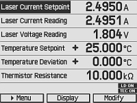 | 測定画面では、測定値やデバイスの状態について簡単に確認することができます。 この画面で主要な設定値も調整することができます。 ご希望の文字サイズにより、1画面の表示情報数(2、4、6)を選べます。 |  | この測定画面は2つの情報を表示するよう設定されています。 文字サイズは簡単に読めるよう最大化しています。 |
| メニュー画面 | 準連続発振設定画面 | ||
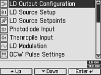 | メニュー画面では、様々な動作モードや選択肢を選ぶことができます。 | 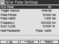 | この画面は準連続発振(QCW)パルスモード設定の入力画面で、設定にはトリガ光源やパルスのパラメータなどがあります。 |
| 半導体レーザ設定画面 | フォトダイオード入力画面 | ||
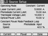 | 半導体レーザ設定画面では、定電流または定電力モードの設定、レーザ電流ならびに出力のリミット値、定出力フィードバックループの速度と、光源などレーザ制御に必要なパラメータを入力することができます。 | 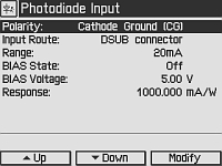 | フォトダイオードセンサに関するパラメータはすべてこのフォトダイオード入力画面から入力します。 |
| 温度コントローラ画面 | 温度モード設定画面 | ||
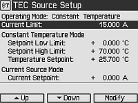 | 動作モード、電流リミット値、電流制御モード設定、温度センサ設定の温度コントローラのパラメータはすべてこの温度コントローラ画面から入力します。 | 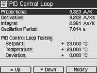 | 手動による最適化の場合、温度のPID制御ループ設定はこの画面から入力します。 温度の設定値と実際値がご覧になれるのでテストに便利です。 |
| PID自動設定画面 | 設定画面 | ||
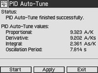 | PID自動設定機能はこの画面から起動させます。コントローラは、現時点の温度設定に適したPIDのパラメータを自動的に選択します。 | 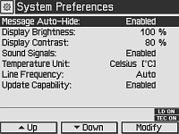 | 設定画面では、画像表示や信号の設定画面などお好みの画面をご覧になれます。 |
半導体レーザーコントローラ用ソフトウェア
下のダウンロードボタンのリンク先には、VISA VXI pnp™、MS Visual Studio™、MS Visual Studio.net™、LabVIEW™および LabWindows/CVI™のドライバ、ファームウェア、ユーティリティ、ITC4000シリーズのレーザーコントローラ、LDC4000シリーズレーザーコントローラ、CLD1000シリーズ小型半導体レーザーコントローラ、TED4000シリーズTECコントローラに関連したサポートドキュメントがあります。
ソフトウェアのダウンロードページには、SCPI、LabVIEW、Visual C++、Visual C#、Visual Basicを使用して様々なコントローラを結合させるリファレンスプログラミングノートもご用意しております。詳細やリンク先についてはソフトウェアダウンロードページの「Programming Reference」のタブをご覧ください。
ドライバーソフトウェア
バージョン3.1.0(2014年4月11日)
参照プログラミング
バージョン3.3(2015年4月8日) - SCPIコマンド
バージョン1.0(2015年6月16日) - LabVIEW、Visual C++、Visual C#、Visual Basic
これらのソフトウェアパッケージは、LabVIEWのバージョン8.5以降をサポートします。お手元のLabVIEWがそれ以前のバージョンの場合は、当社にご相談ください。
PIDの基礎
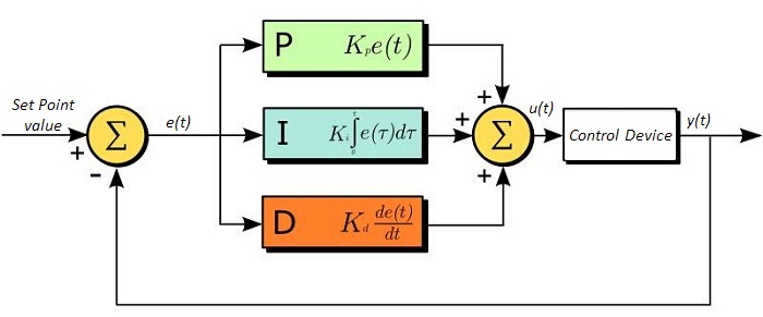
PID回路は制御ループフィードバックコントローラとしてよく用いられており、さまざまなサーボ回路として広く使われています。 PIDとは、それぞれ比例(Proportional)、積分(Integral)、微分(Derivative)の頭文字で、PID回路の3つの制御設定を表しています。 サーボ回路の役割は、システムを長時間所定値(目標値)に保持することです。 PID回路は、出力を目標値に保持するため、主に目標値と出力値の差をエラー信号として発生させることにより、システムをアクティブ制御しています。 3つの制御は、時間依存型エラー信号に関連しています; 端的に言うと、次のように考えることができます。 比例は出力値のエラー、積分は過去の累積エラー、微分はエラーの予測によっています。 各制御の結果は、その後回路の電流を調整する加重和にフィードされます(u(t))。 この出力は制御デバイスへ送られ、その値は回路へとフィードバックされ、回路の出力を目標値に到達させ保持するようアクティブ安定化の処理が行われます。 以下のブロック図は、PID回路の動作を簡略化したものです。 システム要求や要件によって、サーボ回路に1つもしくは複数の制御を使用することができます(例: P、I、PI、PD、PID)。
PID回路の適正な制御設定によって、最小限のオーバーシュート(目標値超過)とリンギング(目標値振動)で、素早い応答速度を実現できます。 ここで半導体レーザの温度安定化に用いられる温度サーボを例にとってみましょう。 PID回路は、最終的には熱電冷却素子(TEC)への電流を自動制御します(多くの場合FET回路上のゲート電圧の制御を通して行われます)。 この例では、電流は操作変数(MV)とします。 サーミスタは半導体レーザの温度モニタとして用いられ、サーミスタにかかる電圧を処理変数(PV)とします。 目標値(SP)の電圧は指定の温度に対応して設定します。 エラー信号e(t)は、SPとPVの差分を表します。 PIDコントローラはエラー信号を発生し、目標値に到達するようMVを変更させます。 例えばもし、e(t)の状態が半導体レーザの過熱を示せば、回路はTECを通してさらに電流を流すよう促します(比例制御)。 比例制御はe(t)に比例するので、半導体レーザを十分な速度で冷却できないかもしれません。 その場合、累積エラーから判断し、目標値へ到達させようと出力を調整し、回路はTECを介してさらに電流量を増加させます(積分制御)。 SPに到達すると(e(t)が0に近づくと)、回路はSPに達するのを見越してTECを通して電流を減少させます(微分制御)。
PID回路は適切な制御を保証するものではないことにご注意ください。 不適切なPID制御の設定は、回路を著しく振動させたり、制御の不安定を引き起こす可能性があります。 正しい動作は、PIDの適正な調整によって得られます。
PID理論
PID制御回路u(t)の出力を得る方程式は以下となります。
Kp= 比例利得
Ki = 積分利得
Kd =微分利得
e(t)=SP-PV(t)
ここから制御ユニットは数学的定義によって定義づけることができ、個々の制御についてもう少し詳しく考察することができます。 比例制御は、エラー信号に比例します。これは、回路が発生させたエラー信号に対する直接的な応答です。
より大きな比例利得は、より大きな変化をエラーへの応答にもたらし、コントローラがシステムの変化に応答できる速度に影響を与えます。 比例利得の値が高いと回路の応答を素早く行えますが、あまりに高い場合は、SP値に対して振動を引き起こしてしまいます。 値が低すぎる場合は、回路はシステム変更への応答性が悪くなります。
積分制御は、比例利得よりさらに1段階ステップが進み、エラー信号の大きさだけでなく、エラーの期間にも比例しています。
積分制御は、比例制御のみによる定常誤差を除去するとともに、回路の応答速度向上に非常に高い効果をもたらします。 積分制御は、未修正の過去のエラーを合計し、エラーにKiを乗算することで、積分応答を出します。 従ってわずかな継続エラーに対しても、大規模な集積積分応答を実現することが可能です。 しかしながら、積分制御の高速応答に起因して、高い利得値による目標値の著しい超過が生じ、振動と不安定性を引き起こします。 低すぎる場合、回路のシステム変更への応答速度が著しく低下します。
微分制御は、比例制御および積分制御から予測される目標値超過とリンギングを低減させます。 回路が時間の経過とともにどう変化しているか(エラー信号の微分から判断)素早く決定し、Kdを乗算することで微分応答を出します。
比例や積分制御と異なり、微分制御は回路の応答を減速させます。 そのため、積分制御や比例制御によって引き起こされた振動を抑制したり、超過を部分的に補うことができます。 高い利得値は回路の応答性にかなりの減速を生じさせ、ノイズや高周波振動が発生しやすくなります(回路が迅速に応答するには低速すぎるため)。 低すぎると、回路はSP値を超過する傾向にあります。しかしながら、SP値を著しく超過するケースは避けなければならず、そのためより高い微分利得(より低い比例利得とともに)が用いられます。 下記の図は、個々のパラメータの利得の増加による影響を示しています。
| Parameter Increased | Rise Time | Overshoot | Settling Time | Steady-State Error | Stability |
|---|---|---|---|---|---|
| Kp | Decrease | Increase | Small Change | Decrease | Degrade |
| Ki | Decrease | Increase | Increase | Decrease Significantly | Degrade |
| Kd | Minor Decrease | Minor Decrease | Minor Decrease | No Effect | Improve (for small Kd) |
チューニング
通常、適切なサーボ制御を得るために、P、I、Dの利得値は個々で調整する必要があります。 どのシステムに対してもどの値にするべき、といった決まった一連のルールがあるわけではありませんが、基本手順に沿ったチューニングは各々のシステムや環境に合わせるのに役立ちます。 概して、PID回路はSP値の超過をわずかに起こし、その後SP値に到達させるため素早く減衰するようにします。
手動による利得設定のチューニングは、PID制御設定において最もシンプルな方法です。 しかしながらこの手順はアクティブで行われ(PIDコントローラがオンとなり、システムに正しく接続されている)、完全に設定するには多少の経験を要します。 PIDコントローラを手動で調整するには、まず始めに積分および微分利得を0に設定します。 出力に振動が現れるまで、比例利得を上げてください。 比例利得はこの値の約半分の値に設定します。 比例ゲイン利得設定後は、任意のオフセットがシステムに合わせた適切なタイムスケールに修正されるまで積分利得を上げてください。 上げすぎた場合は、SP値の著しい超過と回路の不安定性が引き起こされます。 積分利得が設定されたら、次に微分利得を上げてください。 微分利得はオーバーシュートを軽減し、システムを迅速にSP値へ収束させます。 微分利得を上げすぎると、大幅な超過が生じます(回路の応答が低速すぎるため)。利得設定を試行することにより、システムが変化へ素早く応答し、SP値の振動を効率よく減衰させるといった、PID回路の性能を最大限にすることができます。
| Control Type | Kp | Ki | Kd |
|---|---|---|---|
| P | 0.50 Ku | - | - |
| PI | 0.45 Ku | 1.2 Kp/Pu | - |
| PID | 0.60 Ku | 2 Kp/Pu | KpPu/8 |
手動によるチューニングは非常に効果的なPID回路の設定方法ですが、ある程度の経験とPID回路および応答についての理解を必要とします。 PIDチューニングのためのZiegler-Nicholsメソッドは、もう少し体系的な手引きとなっています。 再び、積分利得と微分利得をゼロ値にセットしてください。 比例利得を回路が振動するまで上げます。 この利得をレベルKuと呼びます。 振動はPuの期間です。 個々の制御回路の各利得は右の表に示しています。
なお、デジタルサーボコントローラDSC1などのデバイスにZiegler-Nicholsメソッドを使用する場合、積分利得と微分利得をサンプルレートで正規化する必要があることにご留意ください。そのためには、表から求めた積分利得をHz単位のサンプルレートで割り、微分利得にHz単位のサンプルレートを乗じる必要があります。
| ITC4002QCL Components |
|---|
| Benchtop Laser Diode/TEC Controller, 2 A / 225 W with 17 V Compliance for QCLs and ICLs |
| Cable TED4000/ITC4000 to Laser Mount, 5 A, 17W2, 17W2 (CAB4000) |
| Cable LDC4000/ITC4000 to Laser Mount, 5 A, 13W3, D-Sub-9 (CAB4005) |
| Mixed D-Sub Connector, 17W2, Male & Female Including 2 High-Current Contacts Each, 20 A (CON4001) |
| Mixed D-Sub Connector, 13W3, Male & Female with 3 High-Current Contacts Each, 20 A (CON4005) |
| USB Cable A-B, 2 m |
| 4000 Series Instrumentation CD |
| ITC4000 Series Printed Operation Manual |
| Certificate of Calibration |
| ITC4005QCL Components |
|---|
| Benchtop Laser Diode/TEC Controller, 5 A / 225 W with 20 V Compliance for QCLs and ICLs |
| Cable TED4000/ITC4000 to Laser Mount, 5 A, 17W2, D-Sub-9 (CAB4000) |
| Cable LDC4000/ITC4000 to Laser Mount, 5 A, 13W3, D-Sub-9 (CAB4005) |
| Mixed D-Sub Connector, 17W2, Male & Female Including 2 High-Current Contacts Each, 20 A (CON4001) |
| Mixed D-Sub Connector, 13W3, Male & Female with 3 High-Current Contacts Each, 20 A (CON4005) |
| USB Cable A-B, 2 m |
| 4000 Series Instrumentation CD |
| ITC4000 Series Printed Operation Manual |
| Certificate of Calibration |
| Posted Comments: | |
Thomas Hümmer
(posted 2024-11-15 09:17:15.327) What does TEC Compliance Voltage >15 V mean? What is the Maximum? We would need >30V. hkarpenko
(posted 2024-11-18 04:13:42.0) Dear Thomas,
thank you for your feedback. >15V means, that the compliance voltage is atleast 15V and can be some digits higher than this value. But it won´t reach 30V. I will contact you directly to discuss this topic further with you. Sam Rubin
(posted 2023-06-08 12:51:47.17) The CAB4005 that comes with the ITC4005QCL was setup for CG. You should mention that in the documentation. Users need to open the connector and move the pin to the second location for it to work in AG dmehmedov
(posted 2023-06-13 08:04:50.0) This is a response from Denis at Thorlabs. Dear Sam, thank you very much for your feedback! The cable has the pin alignment as specified on the tab "Pin Diagram" on the product page. This pin assignment should not be changed since by doing so the laser diode may be at risk of damage. Setting up for AG or CG for the laser diode (and for the photodiode if present) should be done on the ITC4005QCL in the settings menu and on the laser diode mount through dedicated hardware switches. I will contact you directly to provide further assistance. Pawel M
(posted 2023-01-25 19:44:56.307) Hi, I have two questions about the current and TEC controllers.
- Can you set the maximum temperature limit to 200C? (this problem has been brought up before and it seems that you can customize the ordered unit?)
- Can one drive purely resistive loads with them by disabling the negative voltage/current output without the need of using additional hardware? hkarpenko
(posted 2023-01-27 06:36:25.0) Dear Pavel,
thank you very much for your feedback. There might be some possibilities for your application. I will contact you directly to discuss this further with you in detail. user
(posted 2019-05-05 10:48:47.95) Could you please let me know what is the speed (bandwidth) of the power feedback control system in the ITC4005QCL module? wskopalik
(posted 2019-05-09 06:44:14.0) This is a response from Wolfgang at Thorlabs. Thank you very much for your inquiry!
The bandwidth of the feedback loop for constant power mode depends on the connected setup (i.e. laser diode, photo diode, thermopile) and on the loop speed which can be set in the menu "LD Source Setup". The loop speed needs to be limited depending on the application to prevent oscillations. It is usually best to look at the resulting waveform on the ANALOG CTL output of the ITC and increase the feedback loop speed as long as no overshoots can be seen in the waveform.
If a photodiode is used as feedback source, the feedback speed can be up to 10kHz in certain conditions. If a thermopile is used, the bandwidth will typically be less than 100Hz due to its slower response time.
I will contact you directly to provide further assistance. info
(posted 2016-10-23 15:06:46.39) "A control output voltage proportional to the laser current is provided for monitoring purposes."
please tell me the bandwidth of this analog output
does it cover dc to 1 MHz? wskopalik
(posted 2016-10-26 04:31:51.0) This is a response from Wolfgang at Thorlabs. Thank you for your inquiry.
The amplifier which creates the signal at the monitor port for the laser current has a 3dB-bandwidth of 150kHz for small sine signals. So you can monitor the internal and external modulation of the driver itself which has a bandwidth of up to 130 kHz. Rectangular signals and pulses may however be shown with rounded edges.
Modulations up to the MHz range could only be achieved by an external Bias-T modulation outside the ITC driver. This would usually take place in the laser diode mount and could not be seen on the monitor port of the driver.
I have contacted you directly to provide further assistance with your application. |
半導体レーザーコントローラーセレクションガイド
Table 137Aと137B は、当社の半導体レーザ用コントローラおよびデュアル半導体レーザ/温度コントローラの主な仕様の一覧です。詳しい内容や仕様について、またはご注文の際には表内の型番をクリックしてご確認ください。
| Table 137A Current Controllers | ||||||
|---|---|---|---|---|---|---|
| Item # | Drive Current | Compliance Voltage | Constant Current | Constant Power | Modulation | Package |
| LDC200CV | 20 mA | 6 V | External | Benchtop | ||
| VLDC002 | 25 mA | 5 V | - | Int/Ext | OEM | |
| LDC201CU | 100 mA | 5 V | External | Benchtop | ||
| LD2000R | 100 mA | 3.5 V | - | External | OEM | |
| EK2000 | 100 mA | 3.5 V | - | External | OEM | |
| LDC202C | 200 mA | 10 V | External | Benchtop | ||
| KLD101 | 230 mA | ≤10 V | External | K-Cube® | ||
| IP250-BV | 250 mA | 8 Va | External | OEM | ||
| LD1100 | 250 mA | 6.5 Va | - | -- | OEM | |
| LD1101 | 250 mA | 6.5 Va | - | -- | OEM | |
| EK1101 | 250 mA | 6.5 Va | - | -- | OEM | |
| EK1102 | 250 mA | 6.5 Va | - | -- | OEM | |
| LD1255R | 250 mA | 3.3 V | - | External | OEM | |
| LDC205C | 500 mA | 10 V | External | Benchtop | ||
| IP500 | 500 mA | 3 V | External | OEM | ||
| LDC210C | 1 A | 10 V | External | Benchtop | ||
| LDC220C | 2 A | 4 V | External | Benchtop | ||
| LD3000R | 2.5 A | -- | - | External | OEM | |
| LDC240C | 4 A | 5 V | External | Benchtop | ||
| LDC4005 | 5 A | 12 V | Int/Ext | Benchtop | ||
| LDC4020 | 20 A | 11 V | Int/Ext | Benchtop | ||
| Table 137B Dual Temperature and Current Controllers | |||||||
|---|---|---|---|---|---|---|---|
| Item # | Drive Current | Compliance Voltage | TEC Power (Max) | Constant Current | Constant Power | Modulation | Package |
| VITC002 | 25 mA | 5 V | >2 W | - | Int/Ext | OEM | |
| ITC102 | 200 mA | >4 V | 12 W | Ext | OEM | ||
| ITC110 | 1 A | >4 V | 12 W | Ext | OEM | ||
| ITC4001 | 1 A | 11 V | >96 W | Int/Ext | Benchtop | ||
| CLD1010LPa | 1.0 A | >8 V | >14.1 W | Ext | Benchtop | ||
| CLD1011LPb | 1.0 A | >8 V | >14.1 W | Ext | Benchtop | ||
| CLD1015c | 1.5 A | >4 V | >14.1 W | Ext | Benchtop | ||
| ITC4002QCLd | 2 A | 17 V | >225 W | Int/Ext | Benchtop | ||
| ITC133 | 3 A | >4 V | 18 W | Ext | OEM | ||
| ITC4005 | 5 A | 12 V | >225 W | Int/Ext | Benchtop | ||
| ITC4005QCLd | 5 A | 20 V | >225 W | Int/Ext | Benchtop | ||
| ITC4020 | 20 A | 11 V | >225 W | Int/Ext | Benchtop | ||
当社では製品組み込み用あるいはラックマウントの半導体レーザ電流&温度コントローラ(組み込み用モジュール、PRO8電流コントロールモジュール、PRO8電流&温度コントロールモジュール)もご用意しております。
| Item # | CAB4007A | CAB4007B | |
|---|---|---|---|
| Click Image to Enlarge | 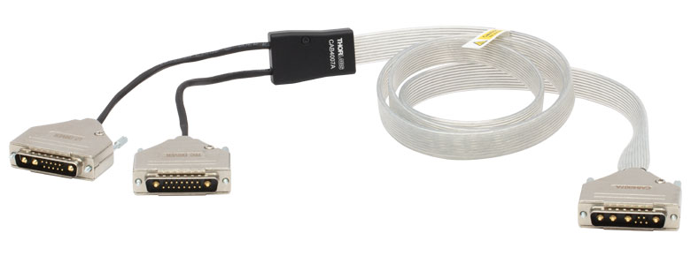 | 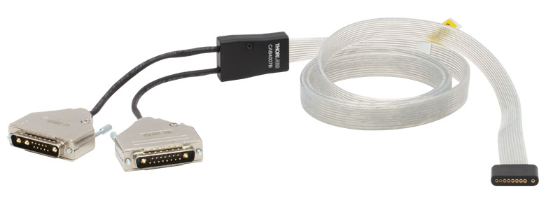 | |
| Description | Hi-Flex LD / TEC Cable for LCM100(/M) Mount | Hi-Flex LD / TEC Cable for 10-Pin HHL Packages | |
| Max Currenta | Pin A1, A2, A3, A4 | 11 A | 10 A |
| Pin 1, 2, 3, 4, 5 | 5 A | 5 A | |
| Connector Type | 17W2 Male and 13W3 Male to 9W4 Male | 17W2 Male and 13W3 Male to a Flat 10-Pin HHL Female Connector | |
| Length | 1.5 m | 1.5 m | |
HHLレーザーパッケージ用コネクターケーブルCAB4007xは、Hi-Flex™†アンシールドケーブルで、一般的なケーブルの許容電流を超える半導体レーザ/TEC用の高電流の用途向けです。
ケーブルCAB4007Aは、9W4コネクタでマウントLCM100/MをITC400xQCLシリーズコントローラに接続します。ケーブルCAB4007Bは、フラット10ピンメス型コネクタであらゆる10ピンHHLレーザを直接ITC400xQCLシリーズコントローラに接続します。 コネクターケーブルCAB4007Bは、LCM100/Mの上部冷却プレートが使用されているときのみご使用いただけます。ケーブルCAB4007A ならびにCAB4007Bのピン配列については「 ピン配列」のタブをご覧ください。
コネクターケーブルCAB4007AまたはCAB4007BをITC400xQCLシリーズコントローラ以外のコントローラに使用するときには、コントローラの仕様に注意し、安全にご使用ください。
†Hi-Flex™はCicoil社の登録商標です。
| Item # | CAB4005 | CON4005 |
|---|---|---|
| Click Image to Enlarge |  | 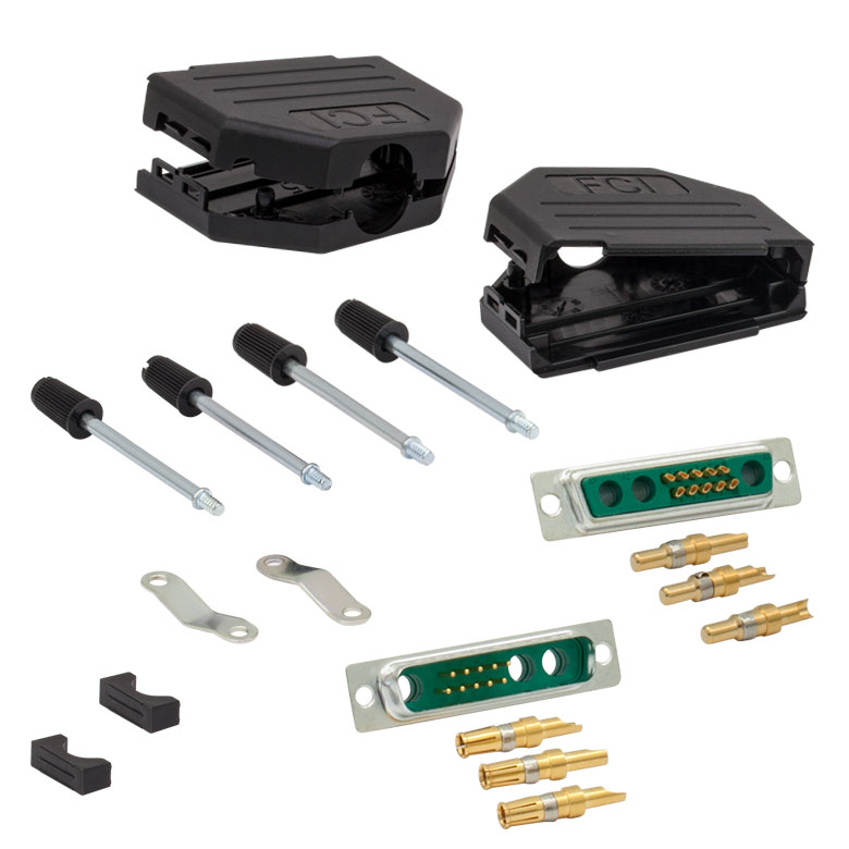 |
| Description | Standard Laser Diode Cable | 13W3 Male and Female Connector Kit (One Each) |
| Max Current | 5 A | 20 A |
| Connector Type | 13W3 Male to DB-9 Male | Loose 13W3 Connectors, Male and Female |
ケーブルCAB4005は、コントローラ ITC4000シリーズと半導体レーザの接続にお使いいただけます。 ご自身でケーブルのカスタマイズを行われるお客様向けにコネクタ13W3のキットもご用意しています。 ケーブルCAB4005ならびにCAB4006のピン配列については「ピン配列」のタブをご覧ください。
ベンチトップ型コントローラITC4002QCLならびにITC4005QCLには、ケーブルCAB4005が1本と、コネクターキットCON4005が付属します(詳細は「発送リスト」タブをご覧ください)。
| Item # | CAB4000 | CAB4001 | CON4001 |
|---|---|---|---|
| Click Image to Enlarge | 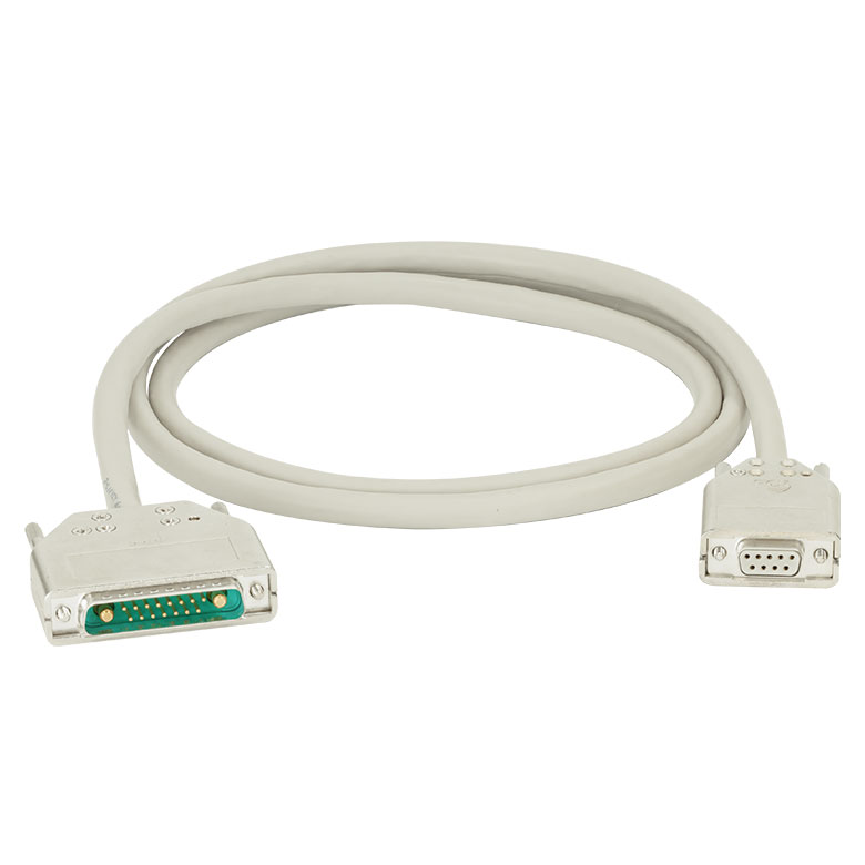 | 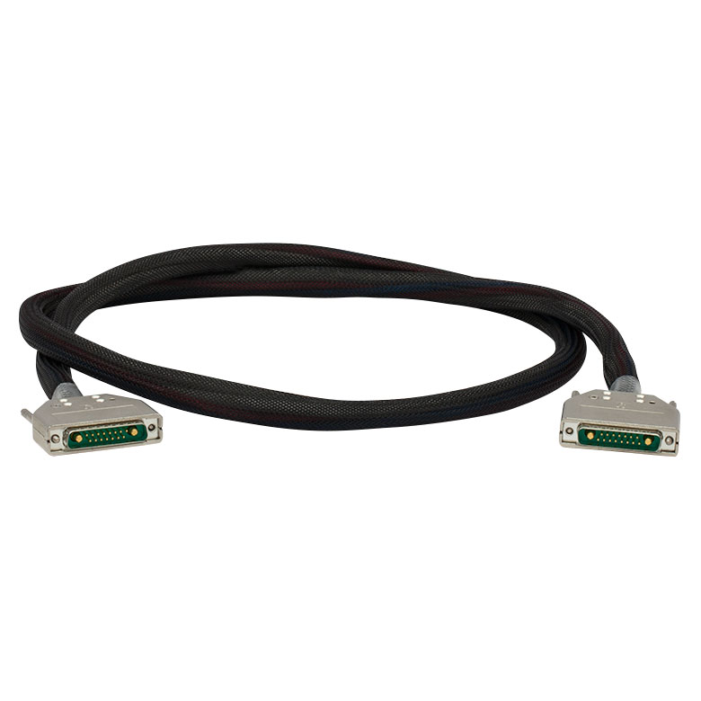 |  |
| Description | Standard TEC Element Cable | High Current TEC Element Cable | 17W2 Male and Female Connector Kit (One Each) |
| Max Current | 5 A | 20 A | 20 A |
| Connector Type | 17W2 Male to DB-9 Female | 17W2 Male to 17W2 Male | Loose 17W2 Connectors, Male and Female |
このケーブルは、コントローラITC4000シリーズとTEC素子の接続にお使いいただけます。 ご自身でケーブルのカスタマイズを行われるお客様向けにコネクタ17W2のキットもご用意しています。 ケーブルCAB4000ならびにCAB4001のピン配列については「ピン配列」のタブをご覧ください。
ベンチトップ型コントローラITC4002QCLならびにITC4005QCLには、ケーブルCAB4000が1本と、コネクターキットCON4001が付属します(詳細は「発送リスト」タブをご覧ください)。
| Calibration Service Item # | Compatible Controllers |
|---|---|
| CAL-ITC4 | ITC4001, ITC4002QCL, ITC4005, ITC4005QCL, ITC4020 |
Thorlabs offers recalibration services for our ITC4000 Series Combined Laser Diode and TEC Controllers. To ensure accurate measurements, we recommend recalibrating the devices every 24 months. The table to the right lists the controllers for which the CAL-ITC4 recalibration service is available.
Requesting a Calibration
Thorlabs provides two options for requesting a calibration:
- Complete the Returns Material Authorization (RMA) form. When completing the RMA form, please enter your name, contact information, the Part #, and the Serial # of the item being returned for calibration; in the Reason for Return field, select "I would like an item to be calibrated." All other fields are optional. Once the form has been submitted, a member of our RMA team will reach out to provide an RMA Number, return instructions, and to verify billing and payment information.
- Enter the Part # and Serial # of the item that requires recalbration below and then Add to Cart. A member of our RMA team will reach out to coordinate return of the item for calibration. Should you have other items in your cart, note that the calibration request will be split off from your order for RMA processing.
Please Note: To ensure your item being returned for calibration is routed appropriately once it arrives at our facility, please do not ship it prior to being provided an RMA Number and return instructions by a member of our team.