 Products Home
Cマウント型レーザ用マウント、温度安定化機能付き
- Laser Mount for C-Mount Semiconductor Lasers
- TEC Cooled with Temperature Stabilization for >20 W of Heat Dissipation
- SM1, 30 mm & 60 mm Cage System, and 1/4"-20 (M6) Post Compatible
LDMC20
Application Idea
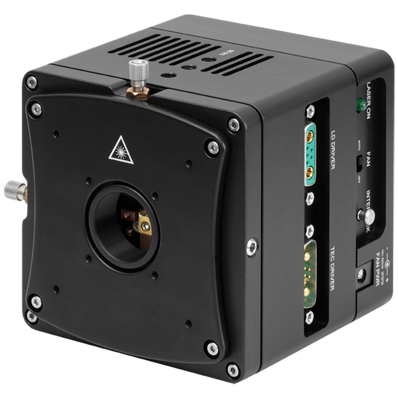
LDMC20 with C-Mount Laser and C037TME-E Lens in a S1TM09 Adapter


Please Wait

Click to Enlarge
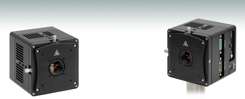
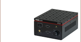
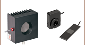
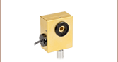
図1: LDMC20(/M)の取付けプラットフォームおよび銅製のヒートシンク
Click to Enlarge
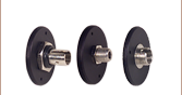
図2: 側面から見たLDMC20(/M)
特長
- Cマウント半導体レーザ用レーザーマウント
- 当社のQCLコントローラと併用すると、内蔵のTEC素子によるアクティブ温度コントロールが可能
- 25 °Cにおいて>20 Wの放熱が可能
- 1タブおよび2タブのCマウントレーザ構成に対応(詳細は「仕様」タブ参照)
- 30 mmおよび60 mmケージシステムに取付け可能
- SM1ネジ付きで非球面レンズアダプタ、ファイバーアダプタ、Ø25 mm~Ø25.4 mm(Ø1インチ)レンズチューブに対応
- ポスト取付け用に6つのM6タップ穴
- QCLコントローラ用の電流ケーブルおよびTECケーブル、ならびにファン用の外部電源が付属
当社のCマウント型レーザーマウントLDMC20/Mは、当社のファブリペロー型(FP)および分布帰還型(DFB)のCマウント半導体レーザを組み込めるように設計されています。内蔵されている電子回路がアクティブな温度制御を行い、25 °Cにおいて20 W以上の放熱が可能です。そのため、このマウントはCマウント型レーザの温度コントロールが必要な際にお使いいただけます。Cマウントレーザは、銅製のヒートシンクに接触させて取り付け、マウントに付属のキャップスクリュで固定します(組立手順は「取付け」タブをご参照ください)。LDMC20/Mは、1タブおよび2タブのレーザ構成の一部に対応します。対応するCマウントデバイスの図は「仕様」タブ内でご覧いただけます。
TEC制御回路がレーザに安定した温度環境をもたらしています。また、ファンの自動スピード制御機能を利用してヒートシンクをアクティブに冷却することで、マウントが空冷されます。このファンは振動隔離されており、振動を最小限に抑えるよう、温度安定化が必要なときのみの駆動となるように設計されています。このマウントを適切な電流でコントロールすれば、レーザの波長を安定化、またはチューニングすることができます。使用中のTECドライバがファンに電源を供給できない場合は、付属の外部電源を用いて作動させることができます。
レーザの出射面は、SM1ネジポートの中心に来るように設定されています。このポートは適切なアダプタを用いてコリメート用非球面レンズを取り付けられるようになっています。Z軸の移動は、SM1ポート内のアダプタをスパナレンチで回転させて行います。刻み付きノブを用いてこのポートのXY軸の精密調整が可能なので、出射したレーザ光をポートの中心に正確に位置決めできます。したがって、レーザ光をコリメート光学素子の中心に素早くかつ簡単に照射することができます。この移動は、フレクシャ設計を利用して行われます。LDMC20/Mの前面カバープレートには、ケージロッドと取り付けるためのタップ穴が8つあり、30 mmまたは60 mmケージステムに対応可能です。
レーザ保護機能として、カスタムの接地構成や、TECコントローラが運転停止中にレーザを駆動しないようにするTECロックアウト回路*があります。内蔵の熱電冷却器により、半導体レーザの温度制御が可能です。
*TECロックアウト機能は、当社の電流および温度コントローラでのみ有効で、必要がない場合は無効にすることができます。
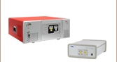
推奨の電流および温度コントローラ
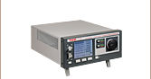
温度および電流のコントロールには、電流コントローラと温度コントローラが組み合わさったITC4002QCLまたはITC4005QCLをこのマウントと一緒にお使いいただくことをお勧めいたします。これらのコントローラはそれぞれ17 Vもしくは20 Vの高いコンプライアンス電圧、2 Aまたは5 Aの最大駆動電流で、当社の中赤外Cマウントレーザに対応する設計になっています。
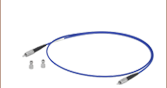
マウントLDMC20/Mには、当社のLDCシリーズ電流コントローラならびにITC4002QCLおよびITC4005QCLを含むITCシリーズ半導体レーザ/TECコントローラすべてに対応する電流ケーブルおよびTECケーブルが付属しています。
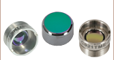
Cマウント型レーザの取扱いについて
Cマウント型レーザは、適切な取扱い方法、ならびに使用方法を守る必要があります。このレーザは静電気により簡単に壊れてしまうので、常に静電気防止策を講じなければなりません。また、このレーザにはモニタ用フォトダイオードが内蔵されていないため、半導体レーザ用に設計された高品質定電流ドライバを使用する必要があります。
TO-CAN型やバタフライ型パッケージとは異なり、Cマウント型レーザのチップは、空気にさらされており、繊細なチップに対する保護がないため、レーザ端面の汚染を防ぐ必要があります。レーザに息を吹きかけたり、煙、埃、油、放熱グリースまたは粘着フィルムに触れさせないようご注意ください。特に埃の蓄積に敏感です。 このパッケージに放熱グリースを使用すると、グリースがしみ出し、レーザ端面を汚染する要因となりますのでご使用にならないでください。放熱グリースの代わりに熱分解グラファイトやはんだは使用可能です。
| LDMC20 Specifications | |
|---|---|
| Supported Laser Diode Packagesa | Single-Tab C-Mount Dual-Tab C-Mount |
| Laser Current (Max) | 20 A |
| TEC Current (Max)b | 11.1 A |
| TEC Voltage (Max) | 14.5 V |
| Heat Dissipation Capacityc | >20 W at 25° C |
| X-Y Translation Range | ±1.0 mm |
| X-Y Translation Resolution | 250 µm/rev |
| Center Threads | SM1 (1.035"-40) Threads 0.535" (13.5 mm) Deep |
| Temperature Sensorsd | 10 kΩ ± 2.2% Thermistor @ 25 °C β = 3984 |
| Operating Temperature | 10 to 40 °C (Non-Condensing) |
| Electrical and Physical Specifications | |
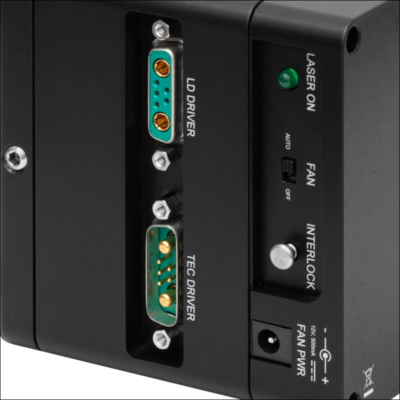
| Laser Interface | 7W2 Mixed Female D-Sub Jack |
| TEC Interface | 7W2 Mixed Male D-Sub Jack |
| Fan Input | 12 VDC, 500 mA |
| Power Supply Connector | 2.1 mm Power Jack |
| Interlock Connector | 2.5 mm Phono Jack |
| Indicators | Green LED when Laser Enabled |
| Size (L × W × D) | 4.00" × 4.00" × 4.05" (101.6 mm × 101.6 mm × 102.9 mm) |
| Weight | 1543 g (3.4 lbs) |
Click to Enlarge
LDMC20の概略図
対応するCマウントレーザの構成
Click to Enlarge
対応しないCマウントレーザの構成
Click to Enlarge
Click to Enlarge
上のグラフは、ファンのスイッチを切った時のLDMC20の放熱を示しています。 データは、3種類の異なる環境温度下で取得されました。
Click to Enlarge
上のグラフは、ファンのスイッチを入れた時のLDMC20の放熱を示しています。 データは、3種類の異なる環境温度下で取得されました。
Click to Enlarge
上のグラフは、温度に対するLDMC20のサーミスタの抵抗値を示しています。 このサーミスタでは、β = 3984です。
Click to Enlarge
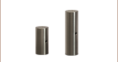
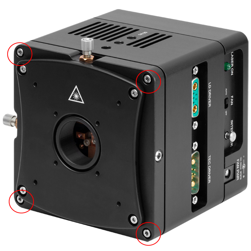
図1:はじめに、付属の5/64インチ六角レンチを用いて、前面の四隅にある六角穴付きネジを取り外します。

Click to Enlarge
図2: Cマウント型レーザをマウント内の所定の位置に慎重に挿入します。 その際、5/64インチ六角レンチを用いてレーザを#2-56六角穴付きネジで固定します。
Click to Enlarge
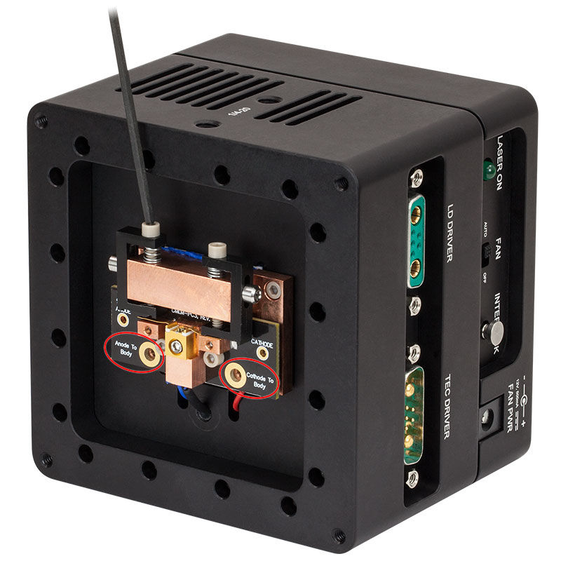
図3: 上の写真にある黒色のプラスチック製ブラケットにより、CマウントのタブとLDMC20(/M)が適切に電気接続されます。 3/32インチの六角レンチ(付属)を使い、タブが小さな銅製のブロックに確実に固定されるまで#4-40六角穴付きネジを締めます。 これらのネジがぴったりとねじ込まれていることをご確認ください。 ネジを強く締めすぎるとマウントやレーザが破損する原因となりますのでご注意ください。シングルタブCマウントレーザでは、付属の#4-40ネジとワッシャを赤い円で示された"Anode To Body"もしくは"Cathode To Body"(レーザの構成によって異なります)の位置に入れてください。
Click to Enlarge
図4: マウントの前面カバーを元に戻します。

Click to Enlarge
図5: ご所望のレンズやアダプタを取り付けます。 この写真ではLDMC20(/M)に、非球面レンズアダプタS1TM09 に取り付けた非球面レンズC037TME-Eを取り付けています。 アダプタをSM1ネジポートに挿入する際には、SPW909をお使いいただけます。このポートは適切なアダプタを用いてコリメート用非球面レンズを取り付けられるようになっています。刻み付きノブを用いてこのポートのXY軸の精密調整が可能なので、出射したレーザ光をポートの中心に正確に位置決めできます。Z軸の調整は、スパナレンチで1度に1/4または1/2回転させた後、LDMC20(/M)から少し離れたところからビーム品質を(できればカメラで)確認しながら行ってください。
注意:Z軸の調整の際はご注意ください。アダプタを回転させ過ぎるとレンズアセンブリとCマウントレーザが接触し、損傷につながる可能性があります。レーザ駆動中は特にご注意ください。詳細は マニュアルのSection 5.7をご参照ください。
レーザのピン接続
D-Subミックスドコンタクトコネクタ 7W2(メス型)
| Pin | Connection | Pin | Connection |
|---|---|---|---|
| A1 | Laser Cathode | 3 | Not Connected |
| A2 | Laser Anode | 4 | Laser Voltage (Anode) |
| 1 | Interlock and Status Return | 5 | Laser Voltage (Cathode) |
| 2 | Interlock and Status Pin |
TECのピン接続
D-Subミックスドコンタクトコネクタ 7W2(オス型)
| Pin | Connection | Pin | Connection |
|---|---|---|---|
| A1 | TEC (+) | 3 | Fan Power |
| A2 | TEC (-) | 4 | TEC Lockout (+) |
| 1 | Thermistor (+) | 5 | Ground |
| 2 | Thermistor (-) |
| Posted Comments: | |
user
(posted 2024-12-05 11:48:23.107) Hi. On page 13, Section 5.4. Active Fan Cooling System, I can see that the mount only has the 2 options: 1) Off and 2) Auto. But in Auto mode, the fan switches On and Off every few minutes. Is there a way to set the fan to "Always On" mode? Is this recommended for my QCL that is operates at 0.6 A and has a forward voltage of around 12 V? Thanks! ksosnowski
(posted 2024-12-10 10:31:35.0) Thank you for reaching out to us. The LDMC20 fan only activates when the heatsink surpasses 30C, so depending on the thermal load this may switch on and off periodically, this is normal. Vibrations from fans can potentially disturb optical setups, so our design allows the fan to only activate as needed during Auto mode, or it can remain Off for smaller heat loads. Our Graphs tab above has the max heat dissipation performance plots both with, and without, the fan activated. LDMC20 can dissipate >20W in a 25C environment so your QCL is well within the thermal limits. I have reached out directly to discuss your application in more detail. Sam Rubin
(posted 2023-06-13 15:23:42.55) would be useful to know the distance from the laser diode to the front of the SM1 thread ksosnowski
(posted 2023-06-13 04:09:05.0) Hello Sam, thanks for reaching out to Thorlabs. For LDMC20 we directly specify the mounting surface as 19.4mm deep from the front flange with the optic threads. As different lasers could have different physical dimensions, the laser chip length should be subtracted from this flange depth to get the emitter depth when using this mount. user
(posted 2022-09-14 17:36:57.15) I wonder if it's possible to see the laser diode facet from the top after removing the Taps? Thanks! ksosnowski
(posted 2022-09-22 04:55:05.0) Thanks for reaching out to Thorlabs. The clamp above the diode securing its pins extends 6mm past the face of the PCB, so this would likely block the top of any installed diode. The images from the "Installation" Tab show above the mechanism that would block this, and the mount wouldn't be operable if this were removed. lukas.perner
(posted 2018-06-23 16:17:37.923) Just a remark on the Imperial C-Mount laser mount: Mounting to any base, e.g. kinetic or magnetic, or even a ball-bearing stage, would be a lot easier if the spacing of the outside 1/4"-20 threads on the side would be 1.00" instead of 1.05". Construction-wise this can't be a problem, as the metric ones have a 25.0mm spacing for their respective threads (being M6 on them).
This change would result in a far better compatibility with ThorLabs mountig options as the standard spacing of breadboards, stages, mounts etc. is 1". YLohia
(posted 2018-06-25 12:23:11.0) Hello, thank you for your valuable feedback. I have posted this on our internal engineering forum for further consideration. user
(posted 2018-05-06 15:05:23.557) Does the integrated LDMXY make this product suitable for vertical mounting using the 60 mm cage system or will the weight (heat sink etc.) press the slip plate against the xy-positioner and prevent the latter from being moved with the screws? YLohia
(posted 2018-05-07 04:26:46.0) Hello, thank you for contacting Thorlabs. The integrated LDMXY is suitable for vertical mounting using the cage system. The screws are as adjustable in this configuration as they are in a typical post-mounted configuration. |