4チャンネルファイバー出力レーザー光源
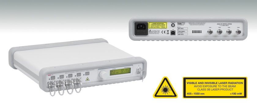
- 4 Laser Output Channels with FC/PC Connectors
- TEC and Controller for Each Channel
- Stable, Low Noise Output
- 31 Power/Wavelength Options Available
MCLS1-CUSTOM
View of Back Panel

Please Wait
特長
- FC/PCコネクタ付きの4つのレーザ出力チャンネル
- 独立した温度制御による高い温度安定性
- 低ノイズ出力
- USBインターフェイス
- 薄型パッケージ、高さ64 mm
- 32の波長から選択可能(Table 1.1参照)
当社の4チャンネルファイバ出力光源は波長の組み合わについてカスタマイズが可能な製品です。また、制御を容易に行うことができ、ファイバ結合も簡単です。レーザ光源はTable 1.1のピグテール付き半導体レーザに対応する構成です。これらの半導体レーザのラインナップは406~1550 nmのスペクトル範囲の波長をもち、光源内であらゆる組み合わせが可能です。この光源では1つ以上のチャンネルを同時にON状態にできますが、前面パネルからの出力調整は同時にはできません。
各半導体レーザは、独立した高精度で低ノイズの定電流電源および温度制御ユニットで駆動されます。直感的なLCDインターフェイスで、各レーザの電流設定と温度制御をモニタリングしながら独立して操作できます。ディスプレイ画面では、選択されたチャンネル番号、光源の出力波長、半導体レーザ用のモニタリング用PDの値から計算して得られる出力パワー、レーザの実際の設定温度が表示されます。
このデバイスには、システムをモニタリングし、 レーザの光強度と温度を制御するマイクロコントローラが付属しています。このレーザ光源はUSB接続に対応し、パワーや温度の調整や、ENABLE/DISABLE状態の選択を遠隔操作できます。背面パネルのアナログ入力部を使えば、外部で生成された波形でレーザを変調できます。損傷を防ぐため、アナログ入力と内部設定ポイントの加算値がレーザのリミットを超えた場合、内蔵のマイクロコントローラが出力を無効にします。
当社では、より多くの波長種類に対応可能で、スーパールミネッセントダイオード(SLD)もお選びいただける、カスタマイズ可能なファイバ出力型の4チャンネル光源MCLS2-CUSTOMもご用意しています。MCLS2-CUSTOMはタッチパネル式で、変調帯域幅は200 kHzとなっています。
安全性
このシステムはクラス3Bの要件を満たすように設計されています。背面パネルにはインターロックがあり、レーザ駆動時にはこれを短絡させる必要があります。レーザが安全ではない条件下では DISABLE状態となるように、扉の開閉によってインターロックをかけることも可能です。電源スイッチは、事故や不要時での作動を防ぐためのキーロックシステムです。光源には、マスタースイッチに加えて各光源を独立して駆動させるENABLEボタンもあり、ご使用の際は個別の光源を自由に選択してENABLE状態にすることができます。各チャンネルに付き1つずつ緑色LEDが付いているので、電流の状態を簡単に認識できます。レーザが動作するまで3秒の遅れがあり、その間はLEDが点滅します。ファイバを出力ポートに接続、または取り外す際には、レーザの電源は必ずお切りください。パワーが10 mWを超える場合は特にご注意ください。
筐体内
MCLS1-CUSTOMにはユニバーサル電源が内蔵されており、電源電圧を選択しなくても100~240 VACで動作します。ヒューズは使いやすいように背面に配置されています。このユニットには、日本用の電源ケーブルが含まれています。選択されたレーザが組み込まれた状態の光源がマニュアルと共に出荷されます。
Table 1.1は、提供可能な波長毎のレーザのリストです。レーザの出力とピグテール付きファイバの種類も示しています。Table 1.1にはない波長と構成については当社までお問い合わせください。Table 1.1に従いご希望のピグテール付き半導体レーザとその位置をご選択ください。
注: MCLS1-CUSTOMはチャンネル1から順に、必ず1つ以上のチャンネルにピグテール付き半導体レーザをお選びの上、ご購入ください。つまり、チャンネル2のレーザを選択する前に必ずチャンネル1を選択しなければなりません。後につづくチャンネルを空欄にした場合、ユニットはそのチャンネルにレーザが組み込まれない状態で出荷されます。空欄のチャンネルについてはご購入後、当社にてレーザを追加することも可能です。その際は事前に当社までご連絡ください。
下記の半導体レーザはMCLS1-CUSTOMとして注文する以外、別途ご購入いただくことはできません。ファイバ出力半導体レーザを単体でご購入を希望する場合、当社ではTO Can型ならびにバタフライパッケージ付きのピグテール付き半導体レーザを豊富に取り揃えております。
| Table 1.1 Specifications | |||||||
|---|---|---|---|---|---|---|---|
| Diode Name | Typical λ | Wavelength Range | Minimum Powera | Typical Power | Laser Type | Monitor Photodiodeb | Fiber |
| MCLS1-406 | 406 nm | 395 - 415 nm | 4.0 mW | 6.0 mW | Fabry-Perot | Yes | S405-XP |
| MCLS1-473-20 | 473 nm | 468 - 478 nm | 15.0 mW | 20 mW | Fabry-Perot | Yes | 460HP |
| MCLS1-488 | 488 nm | 483 - 493 nm | 18.0 mW | 22 mW | Fabry-Perot | Yes | 460HP |
| MCLS1-520A | 520 nm | 510 - 530 nm | 10.0 mW | 15.0 mW | Fabry-Perot | Yes | 460HP |
| MCLS1-635 | 635 nm | 630 - 640 nm | 2.5 mW | 3.5 mW | Fabry-Perot | Yes | SM600 |
| MCLS1-638 | 638 nm | 628 - 648 nm | 10.0 mW | 15.0 mW | Fabry-Perot | Yes | SM600 |
| MCLS1-642 | 642 nm | 635 - 645 nm | 15.0 mW | 20.0 mW | Fabry-Perot | Yes | SM600 |
| MCLS1-658 | 658 nm | 648 - 668 nm | 9.5 mW | 14.0 mW | Fabry-Perot | Yes | SM600 |
| MCLS1-660 | 660 nm | 653 - 663 nm | 15.0 mW | 17.0 mW | Fabry-Perot | No | SM600 |
| MCLS1-670 | 670 nm | 660 - 680 nm | 1.5 mW | 2.5 mW | Fabry-Perot | Yes | SM600 |
| MCLS1-670-4 | 670 nm | 660 - 680 nm | 4.0 mW | 5.0 mW | Fabry-Perot | Yes | SM600 |
| MCLS1-685 | 685 nm | 675 - 695 nm | 10.0 mW | 13.5 mW | Fabry-Perot | Yes | SM600 |
| MCLS1-705 | 705 nm | 695 - 715 nm | 10.0 mW | 15.0 mW | Fabry-Perot | Yes | SM600 |
| MCLS1-730 | 730 nm | 720 - 740 nm | 12.5 mW | 15.0 mW | Fabry-Perot | Yes | SM600 |
| MCLS1-785 | 785 nm | 770 - 800 nm | 6.0 mW | 7.5 mW | Fabry-Perot | Yes | 780HP |
| MCLS1-785-25 | 785 nm | 780 - 790 nm | 20.0 mW | 25.0 mW | Fabry-Perot | No | 780HP |
| MCLS1-808-20 | 808 nm | 803 - 813 nm | 20.0 mW | 25.0 mW | Fabry-Perot | Yes | SM800-5.6-125 |
| MCLS1-830 | 830 nm | 820 - 840 nm | 8.0 mW | 10.0 mW | Fabry-Perot | Yes | SM800-5.6-125 |
| MCLS1-850 | 850 nm | 840 - 860 nm | 7.5 mW | 10.5 mW | Fabry-Perot | Yes | SM800-5.6-125 |
| MCLS1-850-MM | 850 nm | 847 - 857 nm | 45.0 mW | 50.0 mW | Fabry-Perot | Yes | GIF625 |
| MCLS1-852 | 852 nm | 847 - 857 nm | 20.0 mW | 25.0 mW | Fabry-Perot | Yes | SM800-5.6-125 |
| MCLS1-915 | 915 nm | 910 - 920 nm | 30.0 mW | 40.0 mW | Fabry-Perot | Yes | SM800-5.6-125 |
| MCLS1-940 | 940 nm | 930 - 950 nm | 25.0 mW | 30.0 mW | Fabry-Perot | Yes | SM800-5.6-125 |
| MCLS1-980 | 980 nm | 965 - 995 nm | 6.0 mW | 9.0 mW | Fabry-Perot | Yes | 980HP |
| MCLS1-1064 | 1064 nm | 1059 - 1069 nm | 20.0 mW | 25.0 mW | Fabry-Perot | Yes | HI1060 |
| MCLS1-1310-15 | 1310 nm | 1290 - 1330 nm | 13.0 mW | 15.0 mW | Fabry-Perot | No | SMF-28e+ |
| MCLS1-1310DFB | 1310 nm | 1307 - 1313 nm | 1.5 mW | 2.0 mW | DFB | Yes | SMF-28e+ |
| MCLS1-1550 | 1550 nm | 1520 - 1580 nm | 1.5 mW | 2.0 mW | Fabry-Perot | Yes | SMF-28e+ |
| MCLS1-1550-10 | 1550 nm | 1530 - 1570 nm | 8.0 mW | 10.0 mW | Fabry-Perot | No | SMF-28e+ |
| MCLS1-1550DFB | 1550 nm | 1540 - 1560 nm | 1.5 mW | 2.0 mW | DFB | Yes | SMF-28e+ |
| MCLS1-1625 | 1625 nm | 1605 - 1645 nm | 10 mW | 15 mW | Fabry-Perot | No | SMF-28e+ |
| Performance Specifications | |
|---|---|
| Display Power Accuracy | ±10% |
| Current Set Point Resolution | 0.01 mA |
| Laser Drive Current per Channel (Max) | 120 mA |
| Temperature Adjust Range | 20.00 to 30.00 °C |
| Temp Set Point Resolution | ±0.01 °C |
| Noise | <0.5% Typical (Source Dependent) |
| Rise/Fall Time | <5 µs |
| Modulation Input | 0 - 5 V = 0 - Full Power |
| Modulation Bandwidth | 80 kHz Full Depth of Modulation |
| General Specifications | |
|---|---|
| AC Input | 100 - 240 VAC, 50 - 60 Hz |
| Input Power | 35 VA Max |
| Fuse Ratings | 250 mA |
| Fuse Type | IEC60127-2/III (250V, Slow Blow Type 'T') |
| Fuse Size | 5 mm x 20 mm |
| Dimensions (W x H x D) | 12.6" x 2.5" x 10.6" (320 mm x 64 mm x 269 mm) |
| Weight | 8.5 lbs (3.9 kg) |
| Operating Temperature | 15 to 35 °C |
| Storage Temperature | 0 to 50 °C |
| Connections and Controls | |
| Interface Control | Optical Encoder with Pushbutton |
| Enable and Laser Select | Keypad Switch Enable with LED Indication |
| Power On | Key Switch |
| Fiber Ports | FC/PC |
| Display | LCD, 16x2 Alphanumeric Characters |
| Input Power Connection | IEC Connector |
| Modulation Input Connector | BNC (Referenced to Chassis) |
| Interlock | 2.5 mm Mono Phono Jack |
| Communications | |
| Communications Port | USB 2.0 |
| Com Connection | USB Type B connector |
| Required Cable | 2 m USB Type A to Type B Cable (Replacement Part Number USB-A-79) |
操作手順の詳細については取扱説明書(Operating Manual)をご参照ください。こちらのマニュアルはレーザ光源MCLS1の出荷時に同梱されます。
Click to Enlarge
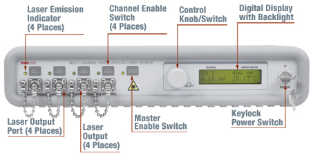
Figure 3.2 前面パネル
Click to Enlarge
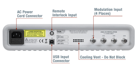
Figure 3.3 背面パネル
ディスプレイ表示について
当社のマルチチャンネルレーザ光源(MCLS)には、各出力チャンネル情報にアクセスするための、画面表示が4分割されているLCDディスプレイが搭載されています(詳細についてはFigure 3.1を参照)。 ディスプレイの左側にある制御ノブで、ご希望のチャンネルをスクロール選択できます。 この制御ノブは、レーザ電流と温度のパラメータにアクセスする選択スイッチでもあります(詳細についてはFigure 3.1を参照)。

Figure 3.1 LCDディスプレイ
- 左上:選択したチャンネルを表示
- 右上:選択したチャンネルの波長を表示
- 左下:半導体レーザ出力のパワーレベルを表示 disableの場合、出力レベルは「0.00 mW」と表示されます。 選択されたレーザにモニタ用PDがない場合、「No PD」と表示されます。
- 右下: 実際のレーザ温度(°C)が表示されます。 初期設定は25 °Cになっていますが、調節可能です。 温度制御は常にアクティブ状態です。また、起動から安定するのに5~10分かかります。
レーザの光出力パワーおよび温度の調節
チャンネル選択後、その選択されたレーザの出力パワーと温度が調節できます。 制御ノブにより、制御速度の調整が可能です。 微調整はノブをゆっくりと回し、粗調整はノブを素早く回します。 レーザの電流調整により、出力パワーがリアルタイムで調整できます。 最初にレーザ光源のユニットの電源を入れた時の初期設定は、出力パワーが完全にオフになっています。 レーザ発光は、光源ごとに異なる閾値の電流値で起こることにご注意ください。
ご希望のチャンネルを選択すると、レーザ電流と温度のパラメータは制御ノブを押すことで調節できます。 制御ノブを1回押すと、レーザ電流の選択、2回押すと温度設定点の選択ができ、3回押すとディスプレイモードに戻ります。 調節の対象となるパラメータは、文字が点滅表示されます。 電流の調節分解能は0.1 mA、温度の調節分解能は0.01 °Cです。
レーザ出力変調
アナログ入力をレーザ出力の変調に使用するか、外部の5 V電源を使用したレーザ出力の遠隔設定が可能です。 最大の5 V電源入力時には、各チャンネルの最大出力が対応します。 実際の出力は、電流の設定と動作温度に依存します。 さらに出力制御ノブの不感帯をなくすには、ユニットの出力を半導体レーザの閾値電流までオフセットします。 ノブを閾値以下に調整すると、すぐに電流が0.0 mA(すなわち、待機モード)になります。 そのため2つの調整モードが可能です。 1つ目の調整モード:スタンバイモードに設定することにより、0~5 Vの入力範囲でアナログ変調が可能となります。 閾値電流以上の作動のために、最小電圧とすることが必要になることが、この調整モードの難点です。 2つ目の調整モード: 制御ノブを調整し、電流をレーザの閾値以上にします。 アナログ変調電圧は5 Vよりも小さくする必要がありますが、DCオフセットは不要です。 実際の入力電圧範囲に制限があるため、変調入力を使用する際にはDCオフセットにご留意ください。
安全インターロックの接続
レーザ光源のMCLSシリーズは、背面パネルにリモートインターロックコネクタが装備されています。 すべての装置はFDAおよびIEC分類にかかわらず、この機能を有しています。 MCLS光源を有効にするには、リモートインターロックコネクタ端子間をショートさせます。 この機能によって、遠隔作動スイッチをコネクタに接続させることができるようになります(オープンドア表示など)。 この機能を使用できるようにするには、Normally Openのスイッチを閉じる必要があります。 スイッチを開いている状態にすると、MCLS光源は自動的に停止します。 またスイッチを閉じる状態に戻すと、MCLS光源はMaster Enableスイッチを押すことで再度操作ができるようになります。

Figure 3.4 インターロックコネクタ
| Specification | Value |
|---|---|
| Type of Mating Connector | 2.5 mm Mono Phono Jack |
| Open Circuit Voltage | +5 VDC with Respect to Chassis Ground |
| Short Circuit Current | ~8 mA DC |
| Connector Polarity | Tip is +5 V, Barrel is Ground |
| Interlock Switch Requirementa | Must be Normally Open Dry Contacts |
レーザの安全性とクラス分類
レーザを取り扱う際には、安全に関わる器具や装置を適切に取扱い、使用することが重要です。ヒトの目は損傷しやすく、レーザ光のパワーレベルが非常に低い場合でも障害を引き起こします。当社では豊富な種類の安全に関わるアクセサリをご提供しており、そのような事故や負傷のリスクの低減にお使いいただけます。可視域から近赤外域のスペクトルでのレーザ発光がヒトの網膜に損傷を与えうるリスクは極めて高くなります。これはその帯域の光が目の角膜やレンズを透過し、レンズがレーザーエネルギを、網膜上に集束してしまうことがあるためです。
安全な作業および安全に関わるアクセサリ
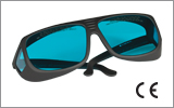
- クラス3または4のレーザを取り扱う場合は、必ずレーザ用保護メガネを装着してください。
- 当社では、レーザのクラスにかかわらず、安全上無視できないパワーレベルのレーザ光線を取り扱う場合は、ネジ回しなどの金属製の器具が偶然に光の方向を変えて再び目に入ってしまうこともあるので、レーザ用保護メガネを必ずご使用いただくようにお勧めしております。
- 特定の波長に対応するように設計されたレーザ保護眼鏡は、装着者を想定外のレーザ反射から保護するために、レーザ装置付近では常に装着してください。
- レーザ保護眼鏡には、保護機能が有効な波長範囲およびその帯域での最小光学濃度が刻印されています。
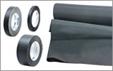
- レーザ保護カーテンやレーザー安全保護用布は実験室内での高エネルギーレーザの遮光にご使用いただけます。
- 遮光用マテリアルは、直接光と反射光の両方を実験装置の領域に封じ込めて外に逃しません。
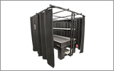
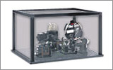
- 当社の筺体システムは、その内部に光学セットアップを収納し、レーザ光を封じ込めて危険性を最小限に抑えます。
- ピグテール付き半導体レーザは、他のファイバに接続、もしくは他のファイバとの接続を外す際には、レーザ出力をOFFにしてください。パワーレベルが10 mW以上の場合には特にご注意ください。
- いかなるビーム光も、テーブルの範囲で終端させる必要があります。また、レーザ使用中には、研究室の扉は必ず閉じていなければなりません。
- レーザ光の高さは、目線の高さに設定しないでください。
- 実験は光学テーブル上で、全てのレーザービームが水平を保って直進するように設定してください。
- ビーム光路の近くで作業する人は、光を反射する不要な装飾品やアクセサリ(指輪、時計など)をはずしてください。
- レンズや他の光学装置が、入射光の一部を、前面や背面で反射する場合がありますのでご注意ください。
- あらゆる作業において、レーザは必要最小限のパワーで動作するようにご留意ください。
- アライメントは、可能な限りレーザの出力パワーを低減して作業を行ってください。
- ビームパワーを抑えるためにビームシャッタや フィルタをお使いください。
- レーザのセットアップの近くや実験室には、適切なレーザ標識やラベルを掲示してください。
- クラス3Rやクラス4のレーザ(安全確保用のインターロックが必要となるレーザーレベルの場合)で作業する場合は、警告灯をご用意ください。
- ビームトラップの代用品としてレーザービュワーカードを使用したりしないでください。
レーザ製品のクラス分け
レーザ製品は、目などの損傷を引き起こす可能性に基づいてクラス分けされています。国際電気標準会議(The International Electrotechnical Commission 「IEC」)は、電気、電子工学技術関連分野の国際規格の策定および普及を行う国際機関で、IEC60825-1は、レーザ製品の安全性を規定するIEC規格です。レーザ製品のクラス分けは下記の通りです
| Class | Description | Warning Label |
|---|---|---|
| 1 | ビーム内観察用の光学機器の使用を含む、通常の条件下での使用において、安全とみなされているクラス。このクラスのレーザ製品は、通常の使用範囲内では、人体被害を及ぼすエネルギーレベルのレーザを発光することがないので、最大許容露光量(MPE)を超えることはありません。このクラス1のレーザ製品には、筐体等を開かない限り、作業者がレーザに露光することがないような、完全に囲われた高出力レーザも含まれます。 |  |
| 1M | クラス1Mのレーザは、安全であるが、望遠鏡や顕微鏡と併用した場合は危険な製品になり得ます。この分類に入る製品からのレーザ光は、直径の大きな光や拡散光を発光し、ビーム径を小さくするために光を集束する光学素子やイメージング用の光学素子を使わない限り、通常はMPEを超えることはありません。しかし、光を再び集光した場合は被害が増大する可能性があるので、このクラスの製品であっても、別の分類となる場合があります。 |  |
| 2 | クラス2のレーザ製品は、その出力が最大1 mWの可視域での連続放射光に限定されます。瞬目反射によって露光が0.25秒までに制限されるので、安全と判断されるクラスです。このクラスの光は、可視域(400~700 nm)に限定されます。 |  |
| 2M | このクラスのレーザ製品のビーム光は、瞬目反射があるので、光学機器を通して見ない限り安全であると分類されています。このクラスは、レーザ光の半径が大きい場合や拡散光にも適用されます。 |  |
| 3R | クラス3Rのレーザ製品は、直接および鏡面反射の観察条件下で危険な可視光および不可視光を発生します。特にレンズ等の光学機器を使用しているときにビームを直接見ると、目が損傷を受ける可能性があります。ビーム内観察が行われなければ、このクラスのレーザ製品は安全とみなされます。このクラスでは、MPE値を超える場合がありますが、被害のリスクレベルが低いクラスです。可視域の連続光のレーザの出力パワーは、このレベルでは5 mWまでとされています。 |  |
| 3B | クラス3Bのレーザは、直接ビームを見た場合に危険なクラスです。拡散反射は通常は有害になることはありませんが、高出力のクラス3Bレーザを使用した場合、有害となる場合もあります。このクラスで装置を安全に操作するには、ビームを直接見る可能性のあるときにレーザ保護眼鏡を装着してください。このクラスのレーザ機器にはキースイッチと安全保護装置を設け、さらにレーザ安全表示を使用し、安全照明がONにならない限りレーザがONにならないようにすることが求められます。Class 3Bの上限に近いパワーを出力するレーザ製品は、やけどを引き起こすおそれもあります。 |  |
| 4 | このクラスのレーザは、皮膚と目の両方に損傷を与える場合があり、これは拡散反射光でも起こりうるとみなされています。このような被害は、ビームが間接的に当たった場合や非鏡面反射でも起こることがあり、艶消し面での反射でも発生することがあります。このレベルのレーザ機器は細心の注意を持って扱われる必要があります。さらに、可燃性の材質を発火させることもあるので、火災のリスクもあるレーザであるとみなされています。クラス4のレーザには、キースイッチと安全保護装置が必要です。 |  |
| 全てのクラス2以上のレーザ機器には、上記が規定する標識以外に、この三角の警告標識が表示されていなければいけません。 |  | |
| Posted Comments: | |
Benjamin Gesemann
(posted 2025-09-16 09:35:02.947) How to change the threshold settings? They are set way to High. For example. 520nm turns on with a minimum of 2mW at the threshold current. To be honest: This is an absolutley unwanted "feature", that the current can not be set to values down to zero. Usefull operation of the Unit is not possible with this setttings. Can you provide Software or serial commands to change the threshold settings? ksosnowski
(posted 2025-09-16 12:07:48.0) Hello Benjamin, thanks for reaching out to us, and sorry to hear of your issues. The minimum and maximum current levels are tuned on the MCLS1's driver during assembly based on the individual laser pigtails installed. Lowering the operating temperature will lower the threshold current of the laser. There is not a way for the user to edit this minimum current through software unfortunately, however a ‘threshold’ of 2mW would be considered excessive with the TEC set at 25C. I have reached out directly to discuss your application further and see if an RMA is necessary. Subhrajit Mukherjee
(posted 2024-11-25 12:36:11.547) I would like to know the actual pulse period of the Laser by applying a square wave of 80KHz using a Keithley Function generator. I need to modify the duty cycles as per requirements. It may vary fro 5%-95% for 80 KHz. is it possible to generate optical pulse in that range using this system? ksosnowski
(posted 2024-11-25 01:33:05.0) Hello Subhrajit, thanks for reaching out to us. 80kHz is the Full Depth Analog Modulation bandwidth for a sinusoidal waveform. The typical modulation rise and fall times of the MCLS1 are <5us, which would unfortunately prohibit shorter pulse durations like this at 80kHz repetition rate. To preserve the sharp edges on a square waveform, one would need to extend the pulse duration to be significantly longer than the rise time and fall time of the driver. I have reached out directly to discuss your application further. Errol Korpinen
(posted 2024-04-24 09:15:30.757) Is there a way to rack mount this unit? or are there any accessible mounting holes? cdolbashian
(posted 2024-04-26 01:27:48.0) Thank you for reaching out to us with this inquiry. Unfortunately this does not have any specific mounting holes, and instead is designed as a benchtop unit. We do sell some empty rack shelves which could be used in conjunction with the MCLS unit if rack mounting is a necessity. I have contacted you to further such a discussion user
(posted 2023-10-13 06:30:06.373) Do you have similar product with multiple lasers which can be selected without reconnecting fiber? ksosnowski
(posted 2023-10-13 12:02:55.0) Thanks for reaching out to Thorlabs. We do not currently have a multi channel laser source with an internal coupler like this. Each channel uses an individually fiber-pigtailed laser diode. However depending on the specific wavelengths used there may be couplers one might use on the output channels to combine the wavelengths to a single channel. Isolators may be useful in that configuration to prevent any possible reflections between channels. ksosnowski
(posted 2023-10-13 12:02:55.0) Thanks for reaching out to Thorlabs. We do not currently have a multi channel laser source with an internal coupler like this. Each channel uses an individually fiber-pigtailed laser diode. However depending on the specific wavelengths used there may be couplers one might use on the output channels to combine the wavelengths to a single channel. Isolators may be useful in that configuration to prevent any possible reflections between channels. Chandramohan Samygounder
(posted 2023-04-11 20:38:10.443) Hello,
What is the power range of λ = 635 2.5 SM600 Fabry-Perot laser?
I mean the minimum to maximum variable power. I understand that the minimum power is the guaranteed power when the nob is set to its maximum. cdolbashian
(posted 2023-04-13 10:37:29.0) Thank you for reaching out to us with this inquiry. At the time of posting this I have reached out to you for clarification, but have not received a response. The min power spec is as you say above. This is the minimum guaranteed output. As far as a range is concerned, you would have a minimum of Zero mW, and a minimum-guaranteed maximum value listed as you see in the specs tab. Thus, in this case, the minimum range would be 0-2.5mW and you can expect 0-3.5 mW as this is the typical value. user
(posted 2023-03-02 16:01:28.08) Hello Can you comment on the ageing of laser diodes that can be mounted inthe MCLS1 ? I need to perform extensive use and wonder about the possibility to change the diodes from time to time. Is it possible ? Cost if you do it ? Can I do it myself ?
Thanks ksosnowski
(posted 2023-03-08 01:47:00.0) Hello, thanks for reaching out to Thorlabs. The lifetime of each diode is different and will depend strongly on the driving conditions like temperature. Operating at increased temperature can act as a catalyst to degradation and accelerate the aging process. We are able to replace the diode pigtails in MCLS1, we can also swap pigtails or upgrade an empty channel space, however the unit needs to return to our factory in NJ for this process. The price of replacing a channel is primarily dependent on the material cost of that specific diode. I have reached out directly to discuss this application further. Manuel Abreu
(posted 2022-09-14 17:25:05.597) can you please confirm that the lead time for the configuration:
MCLS1-Custom, 4-Channel Laser Source, TEC Stabilized, USB, Controller, €3731.954
Channel 1: λ = 406 4 S405-XP Fabry-Perot, €659.03
Channel 2: λ = 705 10.0 SM600 Fabry-Perot, €772.65
Channel 3: λ = 915 30.0 SM800-5.6-125 Fabry-Perot, €909
Channel 4: Empty
is actually 7-10 days ?
This is a critical factor for our decision
Best regards ksosnowski
(posted 2022-09-14 02:12:59.0) Hello Manuel, thanks for reaching out to Thorlabs. As these units are made to the user's selected configuration, there is always some build time when an order is placed. For future inquiries like this please reach us directly at techsupport@thorlabs.com regarding customs or sales@thorlabs.com regarding stock item lead times. I have reached out directly to discuss this configuration in further detail. Christian Haffner
(posted 2021-07-02 03:58:34.883) Could you please comment on the wavelength accuracy of the various laser options for the 1550nm or 16hundred wavlength ratne? YLohia
(posted 2021-07-02 09:38:05.0) Thank you for contacting Thorlabs. The wavelength range for all the component laser diodes can be found on Page 3 of the manual here: https://www.thorlabs.com/_sd.cfm?fileName=TTN182036-D02.pdf&partNumber=MCLS1-CUSTOM. Jeannine Knight
(posted 2021-01-11 12:33:05.38) Are the specified power outputs of each diode at the diode itself? If so, what is the coupling efficiency? For example for the 1310 nm, 2.5 mW diode, what power is actually coming out of the box into my fiber? asundararaj
(posted 2021-01-12 10:20:01.0) Thank you for contacting Thorlabs. The powers specified are the outputs from the MCLS1, which take into account the different losses at the diode-fiber interface. Atanu Bag
(posted 2020-11-11 21:42:30.047) Fiber patch cables are included with this product or we have to purchase separately? If so please recommend YLohia
(posted 2020-11-12 10:06:59.0) Fiber patch cables are not included with this product. The exact cable depends on the channel you intend to connect it with. Please refer to the cross reference table below and click on the hyperlinked fiber part number next to the appropriate laser. The fiber page that opens from that link will contain the list of all available stock patch cables that contain that fiber. If you have further questions, please feel free to email us directly at techsupport@thorlabs.com. user
(posted 2020-11-11 21:19:59.343) Hi, we are interested in generating pulsed light using 4-channel Fiber-Coupled Laser Source with 406 nm Diode (MCLSI-406). We understand by using an external Function Generator we can modulate the output till 80 kHz.
Is it possible to achieve 80 kHz modulation using Square wave input? We are curious about any distortion/lag in the output signals while using an external function generator for giving square wave input. I mean can we obtain exact square wave output (@406 nm) till 80 kHz.
Kindly let us know limitations and feasibility of the above source for our experiment. asundararaj
(posted 2020-12-04 02:11:39.0) Thank you for contacting Thorlabs. Square waves can be used with the MCLS1 however, it is still limited by the system bandwidth. This means that rise and fall time will be bandwidth limited and can be estimated by rise time = 0.35/BW. If the square wave is close to the analog bandwidth, the signal will start to distort and look like a sine wave. A square wave is a combination of the fundamental frequency and higher order secondary frequencies to create a short rise and fall edge. These secondary frequencies will be filtered out leaving just the primary frequency. In reality the square wave signal should be 10X less than the limit to produce a square wave output, in this case ~8kHz. Atanu Bag
(posted 2020-11-10 22:15:42.28) Hi,
We are interested in generating pulsed light using 4-channel Fiber-Coupled Laser Source with 406 nm Diode (MCLSI-406).
Is it possible to connect external Function Generator to modulate the output light pulse with high frequency (e.g., 1kHz and beyond). Kindly let us know limitations and feasibility of the above source for our experiment. YLohia
(posted 2020-11-11 09:45:16.0) Hello, these units are specified for 80 kHz full-depth modulation bandwidth when used with a 0 - 5 V signal from a function generator (see Specs tab). Fur further information, please refer to the "Modulating the Laser Output" section on the "Operation" tab. asundararaj
(posted 2020-12-04 01:34:55.0) Thank you for contacting Thorlabs. Square waves can be used with the MCLS1 however, it is still limited by the system bandwidth. This means that rise and fall time will be bandwidth limited and can be estimated by rise time = 0.35/BW. If the square wave is close to the analog bandwidth, the signal will start to distort and look like a sine wave. A square wave is a combination of the fundamental frequency and higher order secondary frequencies to create a short rise and fall edge. These secondary frequencies will be filtered out leaving just the primary frequency. In reality the square wave signal should be 10X less than the limit to produce a square wave output, in this case ~8kHz. Daniel Bivolaru
(posted 2020-07-24 09:58:55.24) Please add detailed product specifications. Thanks. asundararaj
(posted 2020-07-25 12:26:04.0) Thank you for your feedback. We will look into adding additional details about the individual MCLS1-CUSTOM diodes. markus.thomas.reichel
(posted 2018-09-06 11:14:30.47) Hi, I used the 1550 nm DFB option to set up a fibre based Mach-Zehnder-interferometer. For symmetric path length it worked well. For asymmetric path length (2 meter difference) the interference signal was fluctuating rapidly. I transformed the signal to the frequence spectrum and observed very high noises from 200Hz to 400Hz. It seems that this is due to wavelength fluctuations of the laser. So do you have some information about the wavelength drift of the 1550nm DFB source? YLohia
(posted 2018-10-29 01:05:16.0) Hello, thank you for contacting Thorlabs.
1. Could you please confirm your laser source is the LP1550-SAD2 inside our MCLS1 4-channel source?
2. Would it be possible for you to use a fast-sampling spectrometer (>400 Hz) to see if there are any wavelength fluctuations?
3. At what time are you taking measurements? The temperature control on the MCLS1 for example takes 5-10 minutes to properly stabilize.
4. Are you taking measurements at 25°C? Any particularly humid environment? You can try a few different operating temperatures to find a a more stable point.
5. What power and current are you operating this diode at? If operating close to the lasing threshold this may greatly affect stability.
6. Could you send a picture of your setup in case there are any other components that may be influencing the issue?
We tried reaching out to you via email to troubleshoot but we never heard back from you. philip.dumont
(posted 2018-04-12 15:35:22.383) Hi,
I am trying to model the performance of a test bed that is using:
4-Channel Fiber-Coupled Laser Source, MCLS1
as a light source. I would like to know if the output is polarized. If it is polarized, is the polarization linear or elliptical.
Thanks,
Philip Dumont YLohia
(posted 2018-04-16 10:21:51.0) Hello Philip, thank you for contacting Thorlabs. The output will be polarized, but to a random polarization state which will most likely be elliptical. The MCLS1 contains for separate laser diodes that are linearly polarized and coupled into their individual single mode fibers (non-polarization maintaining). This essentially "scrambles" the polarization and depends on any external stress imposed on the fiber as well as the ambient temperature. Thus, we cannot guarantee a specific polarization state on the output. ax1c15
(posted 2017-09-07 20:58:55.103) Dear Sir/Madam,
I have a 4-Channel Fibre-Coupled laser source.
https://www.thorlabs.com/newgrouppage9.cfm?objectgroup_id=3800
One of the channels is 808nm. What is the coherent length of the laser (~10cm?)?
Also, I have the following laser
https://www.thorlabs.com/thorproduct.cfm?partnumber=S1FC1550PM
I found out that when I increase the power more than a certain level (~0.32mW)
the beam it is not coherent anymore (I am doing interferometric experiments with modulated signals etc.).
What is the coherent length of this source?
What is happening if I overcome this power level? The coherent length changing with power? tfrisch
(posted 2017-09-26 04:14:31.0) Hello, thank you for contacting Thorlabs. Coherence length will be related to the linewidth, so for a Fabry-Perot diode at 808nm, I would expect a coherence length on the order of 0.3mm to 3mm. The optical path length for each arm should be matched to within this. As for the change of coherence with power, it is possible that either temperature or back reflections in the system are causing a change in coherence. I will reach out to you to troubleshoot this as coherence is not directly related to power. user
(posted 2017-05-25 12:41:17.697) Hey, looking for some nice laser source and this looks perfect. What is the coherence length (typical or order) of these LDs (Fabry-Perot)? Thank you! Paul nbayconich
(posted 2017-06-08 05:42:07.0) Thank you for contacting Thorlabs. The coherence length is determined by the longitudinal mode structure of the fabry perot diodes which is a function of the temperature and current of the fabry perot diode. Since the spectrum is a series of discrete narrow peaks corresponding to the cavity modes it is difficult to determine the coherence length. The typical coherence length for the fabry perot diodes will be only a few cm. I will contact you directly with more information about the coherence length of these fabry perot diodes. cbrideau
(posted 2014-04-04 18:01:53.923) Hey guys, my argon laser looks like it is about to quit and I am in the market for a replacement. The two lines we use are 488 and 457nm. I see 488 is standard, but do you offer 457, or 454nm as an option? I have seen a 454nm direct diode from other vendors and was wondering if Thor has access to this wavelength. jvigroux
(posted 2014-04-09 08:55:03.0) A resposne from Julien at Thorlabs: Thank you for your inquiry! The two wavelengths you mention could be efficiently covered using a 490nm and a 455nm. The current filters we use hwoever do not allow for simultaneous operation of those two wavelengths. In order to see if we could use another one, we would need to know all the wavelenths that would be needed in your configuration. I iwll contact you directly. antony.galea
(posted 2013-09-25 09:25:52.387) Dear Sir/Madam,
I am required to complete a laser safety survey by my organization, in which I specify the class of all devices I work with. The MCLS1 is rated as a IIIB device however, it is stated that many of the sources are class IIIR, please specify which sources are considered class IIIR/B.
In specific I am presently interested in the 473nm and 488nm sources.
Thanks jlow
(posted 2013-09-26 14:10:00.0) Response from Jeremy at Thorlabs: We will contact you directly to provide the laser class rating for your laser. sharrell
(posted 2013-01-15 17:20:00.0) Response from Sean at Thorlabs: Thank you for your feedback. We have added a download page for this driver package: http://www.thorlabs.com/software_pages/ViewSoftwarePage.cfm?Code=MCLS1, as well as a new "Software" tab on this page with a link. We will also add this page to our dowload section located under the "Services" menu at the top of the page shortly. ashaw
(posted 2013-01-15 13:33:59.307) Hello,
I can't find the CD containing the driver for my MCLS1. Is there a way to download the driver from the internet?
Thanks tcohen
(posted 2012-07-10 14:42:00.0) Response from Tim at Thorlabs: The minimum power spec references the power that can be guaranteed in an individual unit being run at the operating current. The maximum power out will be the power achieved on the operating current of an individual unit and is best represented by our typical power specification. In this case, it would be 10.5mW. lumz04
(posted 2012-07-06 02:33:48.0) hi, for each channel of laser source, I got the parameter of "Minimum Power", for example
Channel 1: MCLS1-850, ? = 850 7.5 mW SM800-5.6-125 Fabry-Perot, $385
So what is the Maximum power of this channel?
Thanks. tmorgus
(posted 2011-11-23 15:59:00.0) Any chance of getting a 535nm or similar green line on this system? I know the green laser diodes have just become available, but it would be extremely useful for microscopy to have this line available on this unit. My dream system would be 404/488/535/638nm. These would match the wavelengths commonly used on confocal microscope systems. user
(posted 2011-11-23 15:56:21.0) Response from Tyler at Thorlabs: I think that this is a great idea and the only potential hurdle I can see is that availability of a green laser diode, which I need to check on. I will contact you to get more information about your application and the power requirements for the green channel. Thank you for providing us with this product idea. cbrideau
(posted 2011-11-22 17:54:13.0) Any chance of getting a 535nm or similar green line on this system? I know the green laser diodes have just become available, but it would be extremely useful for microscopy to have this line available on this unit. My dream system would be 404/488/535/638nm. These would match the wavelengths commonly used on confocal microscope systems. bdada
(posted 2011-10-26 00:22:00.0) Response from Buki at Thorlabs:
Thank you for your feedback. We are working on getting this data and will update our website with additional data soon. rhs
(posted 2011-09-08 11:06:25.0) I would like to know the spectrum (or at the very least the linewidth) of the two 780 nm modules and of the 1064 nm module. jjurado
(posted 2011-08-01 09:58:00.0) Response from Javier at Thorlabs to md.hai: Thank you very much for contacting us! The linewidth of the laser diode used in the MCLS1-850 modules is 0.60 nm. md.hai
(posted 2011-07-29 17:27:15.0) What is the linewidth of the MCLS1-850 laser modules? Thorlabs
(posted 2010-11-30 09:11:53.0) Response from Javier at Thorlabs to kotov: There are a couple of options to consider. We could perhaps modify the firmware of the MCLS1 to integrate a trigger feature, or you could use a USB DAQ card with four analog outputs. You could provide the modulation signal this way and develop the trigger through your own application. I will contact you directly to discuss your requirements. kotov
(posted 2010-11-23 11:30:46.0) I would like to use MOD IN inputs and Ive tested manually with TTL pulse and attenuator the usable range of amplitude attenuation.
But I would like to use a USB unit with one trigger input and 4 independent amplitude modulated outputs with time width of the input signal (USB controllable). Can you recommend me what device will work for me? USB is prefferable but Ethernet, RS232, RS485 devices can be used as well.
What are limitations on the MOD IN signal pulse width? steffen.michaelis
(posted 2010-10-25 17:56:52.0) For the 4-ch fiber coupled laser source (MCLS1), is it possible to change a laser diode at a later date? Or add another channel if it is initially bought with 2-ch installed? klee
(posted 2009-12-09 14:50:05.0) A response from Ken at Thorlabs to moweirong: The highest guaranteed output power we can do is 8 mW for 658 nm and 10 mW for 785nm. moweirong
(posted 2009-12-09 14:03:12.0) Thanks, klee. Then is it possible to get a smaller optical power value around 660 nm and 780nm, like 10-20 mW? klee
(posted 2009-12-09 11:14:01.0) A response from Ken at Thorlabs to moweirong: The MCLS1 has laser pigtails inside and our typical coupling efficiency is 20%, meaning the output power at the fiber tip is only 20% of the power of the laser diode. Therefore, in order to have 30mW at the fiber output, we will need to use diodes with 150mW. Unfortunately, we do not have the laser diodes with such high power at the wavelengths that you are interested in. moweirong
(posted 2009-12-08 19:15:36.0) For this 4-ch fiber coupled laser source (MCLS1), is it possible to costomize the laser diodes so that the power at wavelength around 660 nm (or 658 nm) and 780 nm (or 785 nm) to be about 30 mW? klee
(posted 2009-09-15 12:51:29.0) A response from Ken at Thorlabs to dtmiller: You can have more than one channel turned on simultaneously. However, you can only adjust the power output one at a time. Please refer to Section 4 of the operating manual for details. dtmiller
(posted 2009-09-14 22:08:57.0) For the 4-channel fiber-coupled laser source (MCLS1), can two or more channels operate simultaneously? cyryl.abidi
(posted 2009-05-21 14:36:38.0) qd |
 Products Home


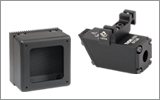


 4チャンネル、レーザ構成カスタマイズ可能