 Products Home
シリコンおよびブラックシリコン増幅フォトディテクタ、自由空間光用
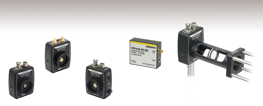
- Wavelength Ranges from 200 nm to 1170 nm
- Maximum Bandwidths Up to 1.5 GHz
- Sensitivities Down to Femtowatt Powers
- Fixed and Switchable Gain Versions
PDA36A2
Switchable Gain
12 MHz Max Bandwidth
Application Idea
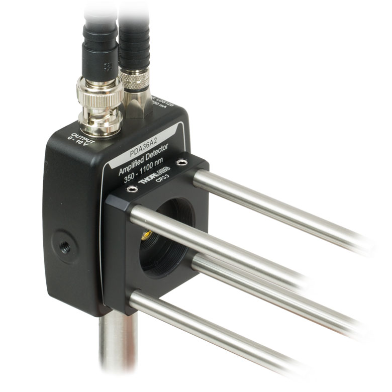
PDA Series Detector with Ø1" Lens Tube Attached to a 30 mm Cage System
PDA10A2
Fixed Gain
150 MHz Max Bandwidth
FPD610-FS-VIS
Fixed Gain
600 MHz Max Bandwidth
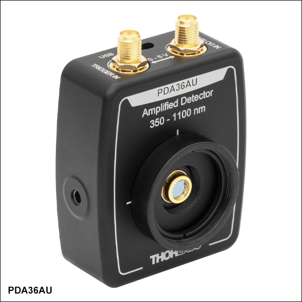
PDA36AU
USB DAQ with Switchable Gain
1 MS/s Sampling Rate


Please Wait
| Table 1.1 Si and Black Si Photodetector Selection Guide | |||
|---|---|---|---|
| Item # | Wavelength Range | Bandwidth | NEP |
| Fixed Gain | |||
| PDA10A2 | 200 - 1100 nm | DC - 150 MHz | 29.2 pW/Hz1/2 |
| PDA10X2 | 240 - 1170 nm | DC - 21 MHz | 21.1 pW/Hz1/2 |
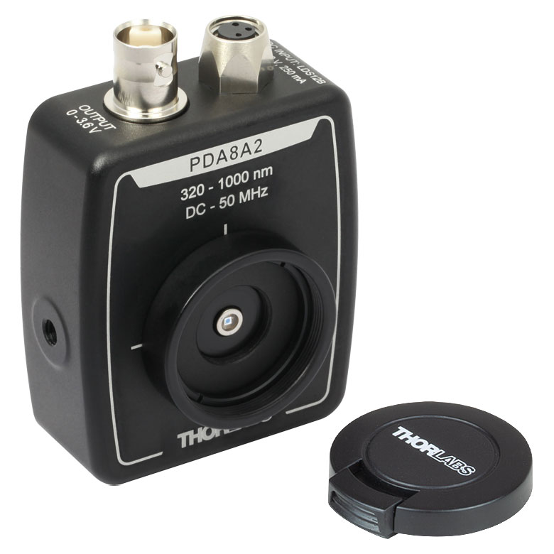
| PDA8A2 | 320 - 1000 nm | DC - 50 MHz | 7.8 pW/Hz1/2 |
| PDF10A2 | 320 - 1100 nm | DC - 20 Hz | 3.0 x 10⁻³ pW/Hz1/2 |
| PDA015A2 | 400 - 1000 nm | DC - 380 MHz | 36 pW/Hz1/2 |
| FPD510-FS-VIS | 400 - 1000 nm | DC - 250 MHz | 6.0 pW/Hz1/2 |
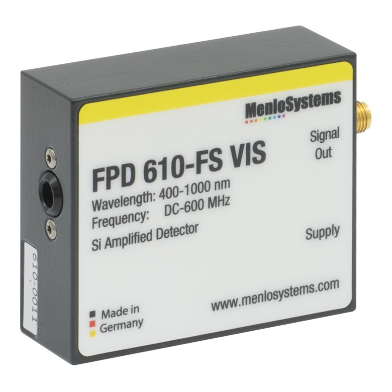
| FPD610-FS-VIS | 400 - 1000 nm | DC - 600 MHz | 11.2 pW/Hz1/2 |
| Switchable Gain | |||
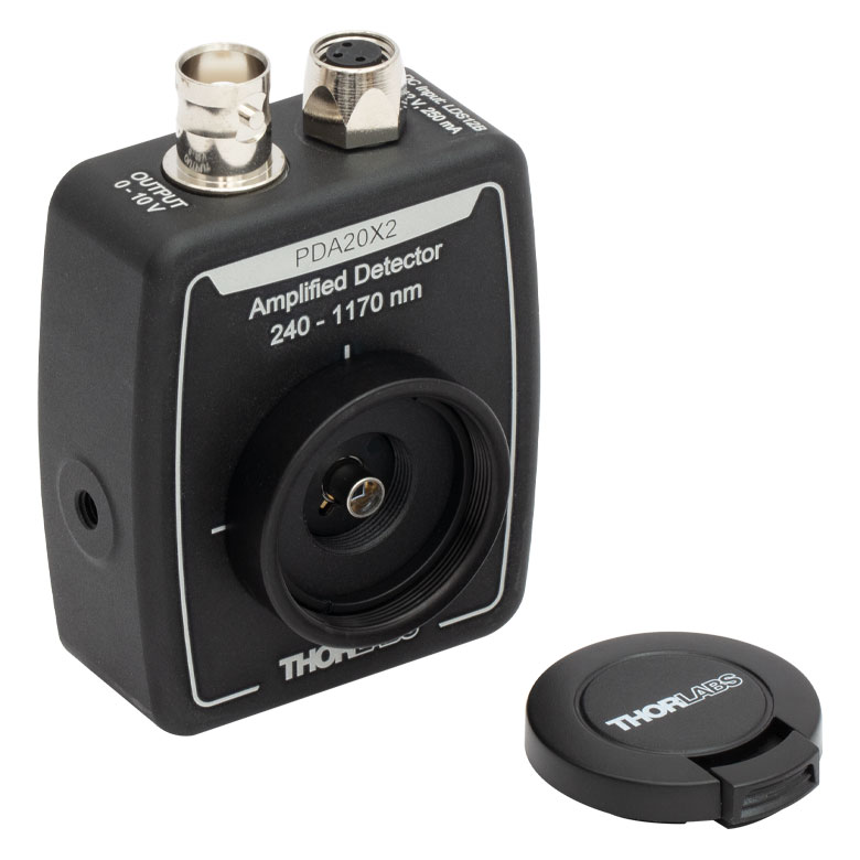
| PDA20X2a | 240 - 1170 nm | DC - 11 MHz | 3.27 - 60 pW/Hz1/2 |
| PDA100A2a | 320 - 1100 nm | DC - 11 MHz | 2.67 - 71.7 pW/Hz1/2 |
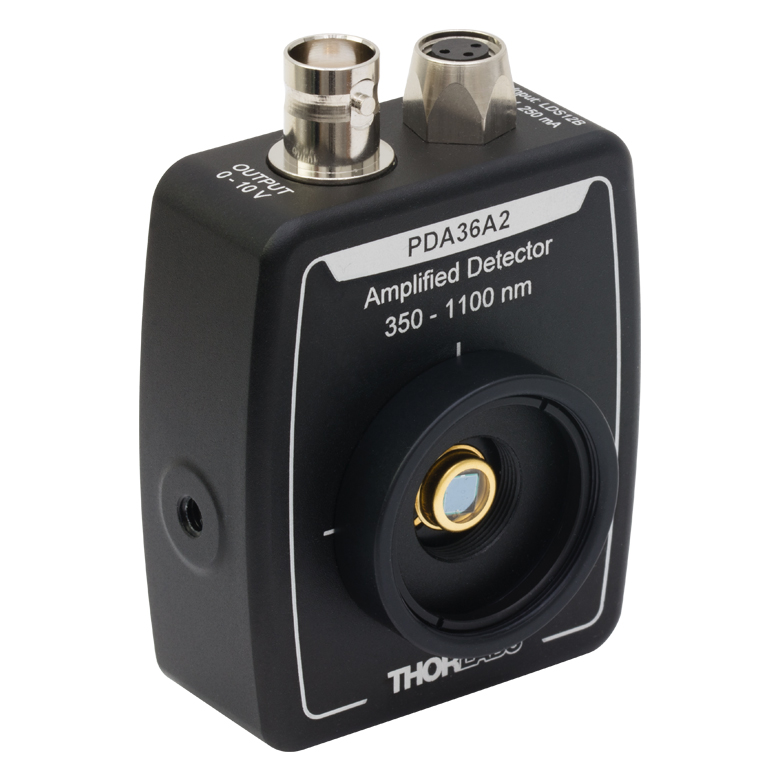
| PDA36A2a | 350 - 1100 nm | DC - 12 MHz | 3.25 - 75.7 pW/Hz1/2 |
| FPD310-FS-VISb | 400 - 1000 nm | 1 - 1500 MHz | 24.0 pW/Hz1/2 |
| Switchable Gain USB DAQ | |||
| PDA36AUa | 350 - 1100 nm | Limited by 1 MS/s ADC Sampling Rate | 3.25 - 75.7 pW/Hz1/2 |
特長
- 波長範囲:200~1170 nm
- 低ノイズ増幅器付き:利得は固定タイプと切り替え可能タイプをご用意
- AC電源アダプタが付属
- 制御用のWindows®PCから電源供給可能なUSBデータ収集(DAQ)デバイスもご用意
- 当社のPDAソフトウェアは、ディテクタの信号と外部アナログ信号の読み取り機能のほか、データ取得のタイミングと表示設定の制御機能を有し、仮想2チャンネルのオシロスコープとしてご使用いただけます。
- 帯域幅≥3 kHzのモデル(型番PDA36AUを除く)の負荷インピーダンス: ≥50 Ω
- 自由空間光結合
Click to Enlarge
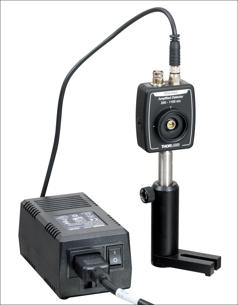
Figure 1.2 PDA10A2と付属の±12 V電源。交換用の電源については下記をご参照ください。
自由空間光用のシリコン(Si)およびブラックシリコン(b-Si)増幅フォトディテクタとして、紫外(UV)から近赤外(NIR)の波長域でご使用いただける製品をご用意しています。当社の増幅フォトディテクタには増幅器が内蔵されており、FPDシリーズの増幅フォトディテクタにはRF増幅器またはトランスインピーダンスアンプが内蔵されています。利得については、固定利得型(最大帯域幅と全トランスインピーダンス利得が固定)と、可変利得型(2段階または8段階で切り替え可能)をご用意しています。
当社のフォトディテクタは、Table 1.1の選択ガイド表でご覧ただけるように、様々なご要求に応えられるように設計されています。インパルス応答1 nsで帯域幅380 MHzのPDA015A2、最小雑音等価電力(NEP)3.0 fW/Hz1/2の高感度なPDF10A2、約400~1000 nmで感度が直線的に変化する利得切り替え可能なブラックシリコン増幅フォトディテクタPDA20X2、利得(帯域幅)の組み合わせが1.51 kV/A(11 MHz)~4.75 MV/A(3 kHz)の間で8段階の切り替えが可能なPDA100A2など、様々な特性や機能の製品がございます。
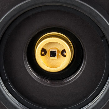
Click to Enlarge
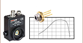
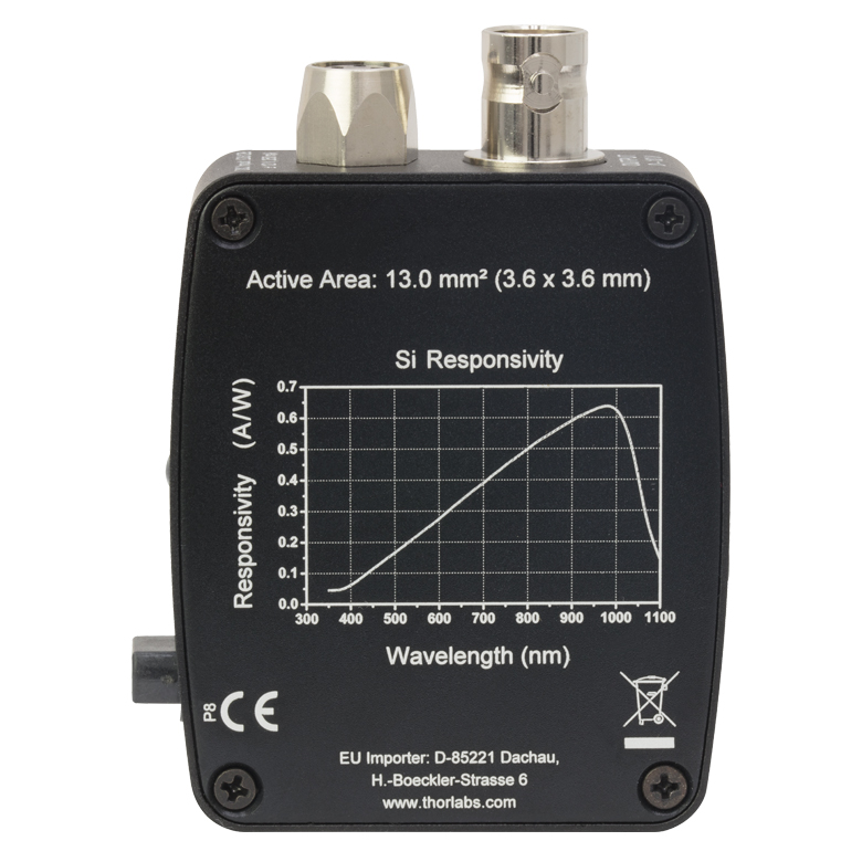
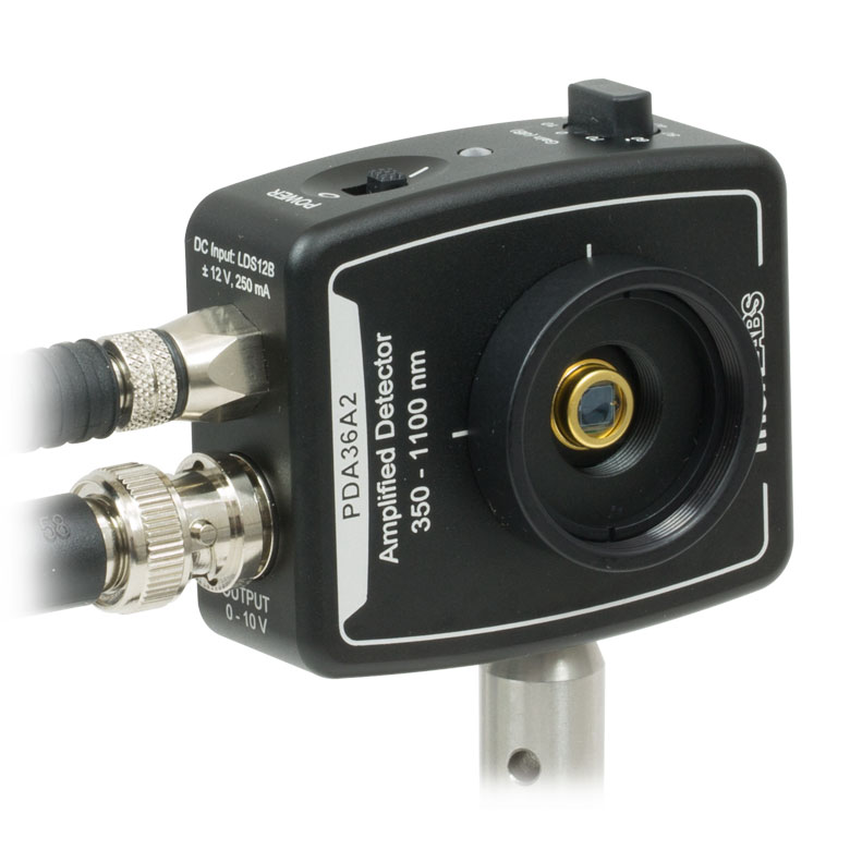
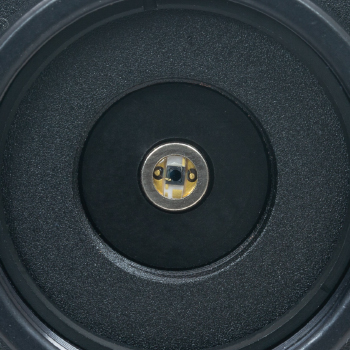
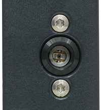
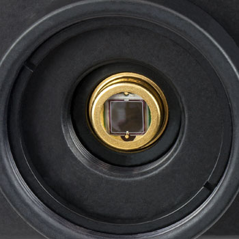
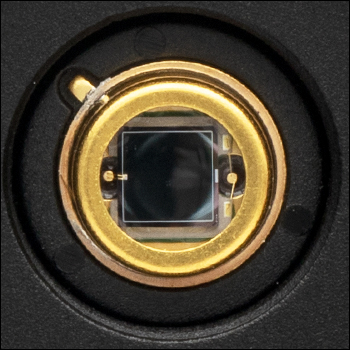
Figure 1.4 ディテクタPDA36A22の背面。PDAシリーズディテクタには分光感度曲線が表示されています。

Click to Enlarge
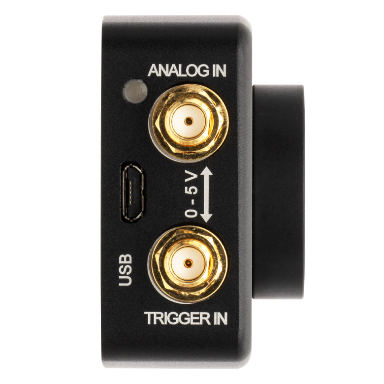
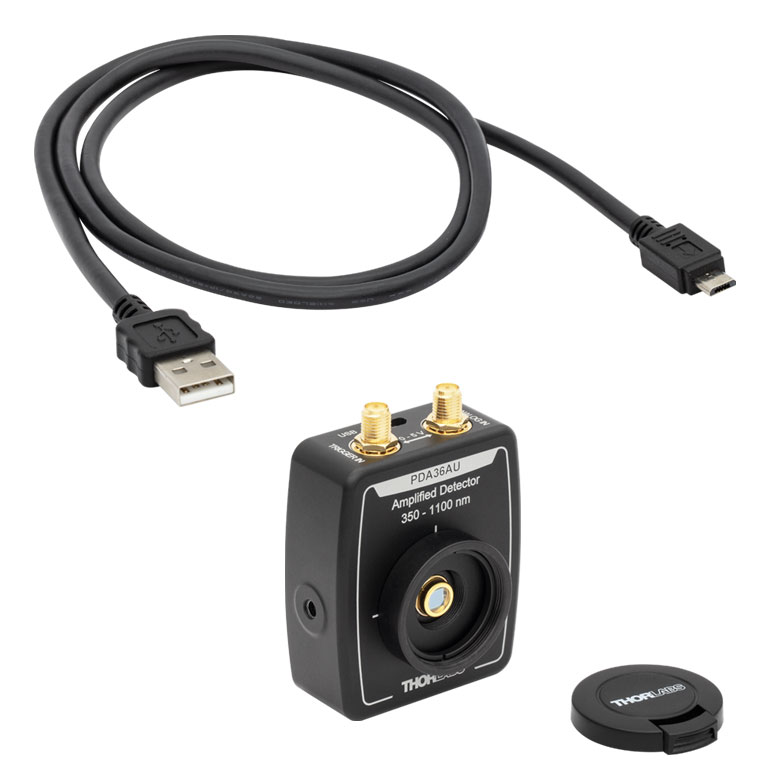
Figure 1.3 USB DAQディテクタPSA36AUは、PCとのUSB 2.0接続により電力が供給され、上の写真のようにSMAコネクタを介してアナログ信号とトリガ信号を入力することができます。付属のソフトウェアは仮想2チャンネルオシロスコープとして機能し、またディテクタの利得とトリガの設定、ディテクタおよびアナログ入力信号の読み取りとデータの保存、保存データの表示などを行うことができます。詳細は「ソフトウェア」タブをご参照ください。
そのほかに、最大利得(帯域幅)の組合せとして、1.51 kV/A (11MHz、PDA36Axは12MHz)~4.75MV/A(3kHz)の範囲で8段階の利得切り替えが可能な、320~1100nm用のPDA100Aと、350~1000nm用のPDA36A2およびPDA36AUをご用意しています。ディテクタPDA36AUはUSB給電方式で、1 MS/sサンプリングの16ビットDAQが内臓されています。Windows PCでPDAソフトウェアを使用すれば、ディテクタの信号と追加されたアナログ入力信号の読み取りのほか、利得やトリガーの設定などができます。 ソフトウェアは仮想2チャンネルオシロスコープとしても機能します。詳細は「ソフトウェア」タブをご覧ください。フェムトワットの感度を有するPDF10A2は低周波数用のデバイスですが、これに接続できる負荷は高インピーダンス(Hi-Z)のみです。その他のSi増幅フォトディテクタは50 Ω~Hi-Zの負荷を接続できます。各デバイスの詳細な仕様は「仕様」タブをご参照ください。
PDAおよびPDFシリーズの全てのディテクタにはSM05内ネジとSM1外ネジが付いており、筐体にはM4および#8-32の両方のネジに対応するタップ穴が付いています。取付け位置や取付け方法については「筐体の特長」タブをご覧ください。各ディテクタには、レンズチューブSM1T1、固定リングSM1RR、および非使用時に検出部を保護するためのプラスチック製ダストキャップ(交換用品の型番はSM1EC2B,、5個入りで別途販売)が付属します。また、デバイスの背面には検出器の分光感度曲線が表示されています(Figure 1.4参照)。
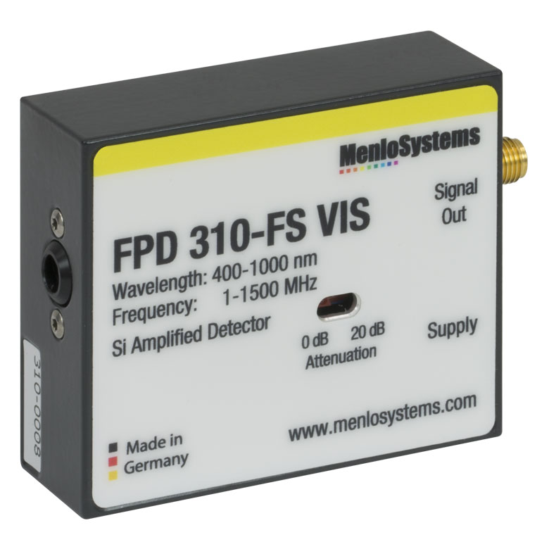
FPDシリーズのフォトディテクタ
FPDシリーズのフォトディテクタには高利得・低ノイズのRF増幅器内蔵型(FPD310-FS-VIS)とトランスインピーダンス増幅器内蔵型(FPD510-FS-VIS、FPD610-FS-VIS)があり、いずれも使いやすいパッケージに納められています。 FPD310-FS-VISは広い帯域幅と極めて短い立ち上がり時間(<1 ns)を必要とする実験用に適しています。その利得は0 dB(0.13 kV/W)と20 dB(1.3 kV/A)の2段階で切り替えられ、帯域は1~1500 MHzです。 FPD510-FS-VISおよびFPD610-FS-VISは利得が固定されており、それぞれの帯域幅は250 MHzおよび600 MHzです。いずれも低レベルの光ビート信号を非常に高い信号対雑音比で検出できるように最適化されています。立ち上がり時間は、FPD510-FS-VISでは2 ns、FPD610-FS-VISでは1 nsです。これらのDC結合型デバイスの3 dB帯域幅は、FPD510-FS-VISでは200 MHz、FPD610-FS-VISでは500 MHzです。FPDシリーズのディテクタはコンパクトなため、組み込み用途(OEM用途)にも適しています。筐体にはポスト取付け用にM4タップ穴が1つ付いています。筐体についての詳細は「 筐体の特長」タブをご覧ください。FC/PCコネクタによるファイバ結合型ディテクタについては、ファイバ結合型Si増幅ディテクタをご覧ください。
電源
電源当社のPDAおよびPDFシリーズの増幅フォトディテクタ(PDA36AUを除く)には±12 Vのリニア電源が付属します。ディテクタPDA36AUはUSB給電方式で、付属のUSB Type-A - Micro-Bケーブルを用いて制御用PCから給電します(Figure 1.3参照)。交換用の電源も別途ご用意しております(下記参照)。USBケーブルの交換用品としては市販の製品をご使用いただけます。電源をAC電源に接続する前に、電源モジュールのAC入力電圧選択スイッチが適切な電圧に設定されていることをご確認ください。電源の投入/切断は、必ず電源のスイッチを使って行ってください。本体のスイッチを入れたままAC電源に接続することはお勧めしません。
FPD510-FS-VIS、FPD610-FS-VIS、FPD310-FS-VISには±15 Vの低ノイズ電源が付属します。
| Table 2.1 Performance Specifications | |||||||
|---|---|---|---|---|---|---|---|
| Item # | Wavelength | Bandwidth | Rise Time | Peak Responsivity | Noise Equivalent Power (NEP)a | Active Area | Operating Temperature Range |
| Fixed Gain | |||||||
| PDA10A2b | 200 - 1100 nmc | DC - 150 MHz | 2.3 ns | 0.44 A/W @ 730 nm | 29.2 pW/Hz1/2 | 0.8 mm2 (Ø1 mm) | 10 to 50 °C |
| PDA10X2 | 240 - 1170 nm | DC - 21 MHz | 20 ns | 0.73 A/W @ 1010 nm | 21.1 pW/Hz1/2 | 1.0 mm2 (1 mm x 1 mm) | 10 to 40 °C |
| PDA8A2 | 320 - 1000 nm | DC - 50 MHz | 7 ns | 0.56 A/W @ 820 nm | 7.8 pW/Hz1/2 | 0.5 mm2 (Ø0.8 mm) | 10 to 50 °C |
| PDF10A2 | 320 - 1100 nm | DC - 20 Hz | 22 ms | 0.6 A/W @ 960 nm | 3.0 x10⁻³ pW/Hz1/2 | 1.2 mm2 (1.1 mm x 1.1 mm) | 10 to 50 °C |
| PDA015A2b | 400 - 1000 nm | DC - 380 MHz | 1.0 ns | 0.47 A/W @ 740 nm | 36 pW/Hz1/2 | 0.018 mm2 (Ø150 µm) | 10 to 40 °C |
| FPD510-FS-VIS | 400 - 1000 nm | DC - 250 MHz | 2 ns | - | 6.0 pW/Hz1/2 | 0.13 mm2 (Ø0.4 mm) | 10 to 40 °C |
| FPD610-FS-VIS | 400 - 1000 nm | DC - 600 MHz | 1 ns | - | 11.2 pW/Hz1/2 | 0.13 mm2 (Ø0.4 mm) | 10 to 40 °C |
| Switchable Gain | |||||||
| PDA20X2 | 240 - 1170 nm | DC - 11 MHzd | N/Ae | 0.73 A/W @ 1010 nm | 3.27 - 60 pW/Hz1/2 | 4 mm2 (2 mm x 2 mm) | 10 to 40 °C |
| PDA100A2b | 320 - 1100 nm | DC - 11 MHzd | N/Ae | 0.72 A/W @ 960 nm | 2.67 - 71.7 pW/Hz1/2 | 75.4 mm2 (Ø9.8 mm) | 10 to 40 °C |
| PDA36A2b | 350 - 1100 nm | DC - 12 MHzd | N/Ae | 0.65 A/W @ 970 nm | 3.25 - 75.7 pW/Hz1/2 | 13 mm2 (3.6 mm x 3.6 mm) | 10 to 40 °C |
| FPD310-FS-VIS | 400 - 1000 nm | 1 - 1500 MHz | 0.5 ns | - | 24.0 pW/Hz1/2 | 0.13 mm2 (Ø0.4 mm) | 10 to 40 °C |
| Switchable Gain USB DAQ | |||||||
| PDA36AU | 350 - 1100 nm | DC - 12 MHzd,f | N/Ae | 0.65 A/W @ 970 nm | 3.25 - 75.7 pW/Hz1/2 | 13 mm2 (3.6 mm x 3.6 mm) | 10 to 40 °C |
利得の仕様
| Table 2.2 Fixed Gain Detectors | |||||
|---|---|---|---|---|---|
| Item # | Gain w/ Hi-Z Load | Gain w/ 50 Ω Load | Offset (±) | Output Voltage w/ Hi-Z Load | Output Voltage w/ 50 Ω Load |
| PDA10A2 | 10 kV/A | 5 kV/A | 10 mV | 0 - 10 V | 0 - 5 V |
| PDA10X2 | 60 kV/A | 30 kV/A | 10 mV | 0 - 10 V | 0 - 5 V |
| PDA8A2 | 100 kV/A | 50 kV/A | 10 mV (Max) | 0 - 3.6 V | 0 - 1.8 V |
| PDF10A2a | 1 x 10⁹ kV/A | - | <75 mV | 0 - 10 V | - |
| PDA015A2 | 50 kV/A | 25 kV/A | 20 mV | 0 - 10 V | 0 - 5 V |
| FPD510-FS-VIS | - | 1.5 x 10⁵ Vpp/Wb 2.5 x 10⁴ V/Wc | - | - | 0 - 1 V |
| FPD610-FS-VIS | - | 2 x 10⁶ Vpp/Wb 2.5 x 10⁵ V/Wc | - | - | 0 - 1 V |
| Table 2.3 Switchable Gain Detectors | |||||||||
|---|---|---|---|---|---|---|---|---|---|
| Item # | Gain Step (dB) | Gain w/ Hi-Z Loada | Gain w/ 50 Ω Loada | Bandwidth | Noise (RMS) | NEPb | Offset (±) | Output Voltage w/ Hi-Z Load | Output Voltage w/ 50 Ω Load |
| PDA20X2 | 0 | 1.51 kV/A | 0.75 kV/A | 11 MHz | 234 µV | 60 pW/Hz1/2 | 8 mV (12 mV Max) | 0 - 10 V | 0 - 5 V |
| 10 | 4.75 kV/A | 2.38 kV/A | 1.3 MHz | 238 µV | 6.15 pW/Hz1/2 | ||||
| 20 | 15 kV/A | 7.5 kV/A | 1.4 MHz | 249 µV | 3.27 pW/Hz1/2 | ||||
| 30 | 47.5 kV/A | 23.8 kV/A | 430 kHz | 246 µV | 3.9 pW/Hz1/2 | ||||
| 40 | 151 kV/A | 75 kV/A | 110 kHz | 245 µV | 3.36 pW/Hz1/2 | ||||
| 50 | 475 kV/A | 238 kV/A | 40 kHz | 250 µV | 5.95 pW/Hz1/2 | ||||
| 60 | 1.5 MV/A | 750 kV/A | 11 kHz | 253 µV | 7.52 pW/Hz1/2 | ||||
| 70 | 4.75 MV/A | 2.38 MV/A | 4 kHz | 265 µV | 5.01 pW/Hz1/2 | ||||
| PDA100A2 | 0 | 1.51 kV/A | 0.75 kV/A | 11 MHz | 268 µV | 71.7 pW/Hz1/2 | 8 mV (12 mV Max) | 0 - 10 V | 0 - 5 V |
| 10 | 4.75 kV/A | 2.38 kV/A | 1.4 MHz | 195 µV | 6.75 pW/Hz1/2 | ||||
| 20 | 15 kV/A | 7.5 kV/A | 800 kHz | 219 µV | 3.36 pW/Hz1/2 | ||||
| 30 | 47.5 kV/A | 23.8 kV/A | 260 kHz | 222 µV | 2.83 pW/Hz1/2 | ||||
| 40 | 151 kV/A | 75 kV/A | 90 kHz | 229 µV | 2.67 pW/Hz1/2 | ||||
| 50 | 475 kV/A | 238 kV/A | 28 kHz | 271 µV | 4.2 pW/Hz1/2 | ||||
| 60 | 1.5 MV/A | 750 kV/A | 9 kHz | 423 µV | 6.24 pW/Hz1/2 | ||||
| 70 | 4.75 MV/A | 2.38 MV/A | 3 kHz | 1.22 mV | 7.88 pW/Hz1/2 | ||||
| PDA36A2 | 0 | 1.51 kV/A | 0.75 kV/A | 12 MHz | 258 µV | 75.7 pW/Hz1/2 | 8 mV (12 mV Max) | 0 - 10 V | 0 - 5 V |
| 10 | 4.75 kV/A | 2.38 kV/A | 1.6 MHz | 192 µV | 5.8 pW/Hz1/2 | ||||
| 20 | 15 kV/A | 7.5 kV/A | 1 MHz | 207 µV | 3.4 pW/Hz1/2 | ||||
| 30 | 47.5 kV/A | 23.8 kV/A | 260 kHz | 211 µV | 3.4 pW/Hz1/2 | ||||
| 40 | 150 kV/A | 75 kV/A | 90 kHz | 214 µV | 3.25 pW/Hz1/2 | ||||
| 50 | 475 kV/A | 238 kV/A | 28 kHz | 234 µV | 3.69 pW/Hz1/2 | ||||
| 60 | 1.5 MV/A | 750 kV/A | 9 kHz | 277 µV | 4 pW/Hz1/2 | ||||
| 70 | 4.75 MV/A | 2.38 MV/A | 3 kHz | 388 µV | 4.29 pW/Hz1/2 | ||||
| FPD310-FS-VIS | 0 | - | 2 x 10⁴ Vpp/Wc 1.3 x 10³ V/Wd | 1 - 1500 MHz | -e | 24.0 pW/Hz1/2 | N/A (AC Coupling) | - | ~1 V |
| 20 | - | 2 x 10³ Vpp/Wc 1.3 x 10² V/Wd | |||||||
| Table 2.4 Switchable Gain USB DAQ Detectora | ||||||||||||
|---|---|---|---|---|---|---|---|---|---|---|---|---|
| Item # | Amplifier GBP | Gain Step (dB) | Gainb | Bandwidthc,d | ADC Sampling Rate | ADC Resolution | Noise (RMS) | NEPe | Offset (±) | ANALOG IN | TRIGGER IN | Powerf |
| PDA36AU | 600 MHz | 0 | 1.51 kV/A | 12 MHz | 1 MS/s | 16 bit | 258 µV | 75.7 pW/Hz1/2 | 8 mV (12 mV Max) | SMA, 0 - 5 V, 50 Ω Input Impedance | SMA, 5 V TTL, 2.3 V High, 1.0 V Low, 1000 Ω Input Impedance | USB 2.0 Type Micro-B |
| 10 | 4.75 kV/A | 1.6 MHz | 192 µV | 5.8 pW/Hz1/2 | ||||||||
| 20 | 15 kV/A | 1 MHz | 207 µV | 3.4 pW/Hz1/2 | ||||||||
| 30 | 47.5 kV/A | 260 kHz | 211 µV | 3.4 pW/Hz1/2 | ||||||||
| 40 | 151 kV/A | 90 kHz | 214 µV | 3.25 pW/Hz1/2 | ||||||||
| 50 | 475 kV/A | 28 kHz | 234 µV | 3.69 pW/Hz1/2 | ||||||||
| 60 | 1.5 MV/A | 9 kHz | 277 µV | 4 pW/Hz1/2 | ||||||||
| 70 | 4.75 MV/A | 3 kHz | 388 µV | 4.29 pW/Hz1/2 | ||||||||
Click to Enlarge
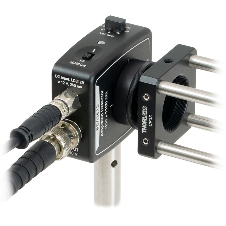
Figure 3.3 PDAおよびPDFシリーズのディテクタ筐体上面(PDA36AUを除く)。筐体上面には電源コネクタ、出力用BNCコネクタ、および電源表示用LEDがあります。 この写真はディテクタPDA20X2です。
Click to Enlarge
Figure 3.2 USB DAQディテクタPDA36AUの筐体上面。筐体上面には、USB 2.0 Micro-Bコネクタ、アナログ入力用SMA端子、トリガ信号入力用SMA端子、および電源表示用LEDが付いています。
Click to Enlarge
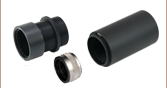
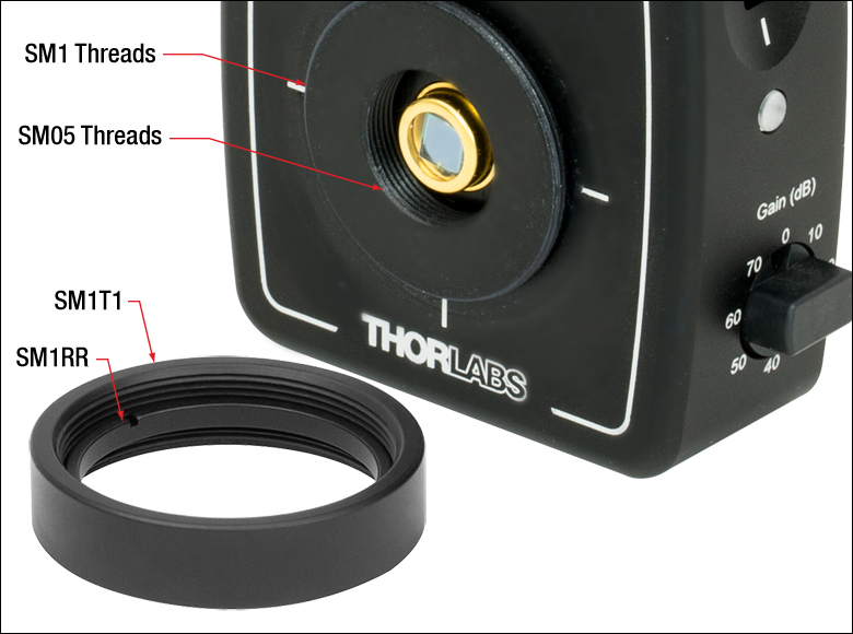
Figure 3.1 PDAおよびPDFシリーズのディテクタには、SM05内ネジとSM1外ネジが付いています。各増幅フォトディテクタにはSM1内ネジ付きアダプタSM1T1が1個付属します。また、PDA015A2、PDA10A2、PDA36A2、PDA100A2、PDF10A2、PDA36AUには固定リングSM1RRが1個付属します。
Si増幅フォトディテクタの筐体の特長
各ディテクタの詳細な図はTable 3.8をご覧ください。
PDAおよびPDFシリーズディテクタ
PDAおよびPDFシリーズディテクタの筐体は薄型で、多くの共通化された要素で構成されています。 Figure 3.1に示すように、各筐体の光入射部にはSM05内ネジとSM1外ネジが付いており、また取り外し可能なSM1内ネジ付きアダプタSM1T1が1個付属しています。SM1T1は厚さ2.8 mmまでの光学素子を保持できます。 各ディテクタには固定リングSM1RRも1個付属します。Figure 3.4~3.7でご覧いただけるように、各ディテクタはØ12 mm~12.7 mm(Ø1/2インチ)ポストを使用して取り付けることができます。 タップ穴がミリ・インチ規格共用のディテクタ(Table 3.8参照)は、筐体が新しく設計された製品です。検出面が筐体の前面と同一平面になるように設計されており、そのためオプトメカニクスシステム内でのアライメントが容易になります。これらのディテクタの背面パネルには、各フォトダイオードの分光感度曲線が刻印されています。 すべてのPDAおよびPDFシリーズディテクタには、ディテクタの保護用にスナップオン式のプラスチック製ダストキャップが1個付属します。交換用のキャップは5個入りで別途販売しています(型番SM1EC2B)。
レンズチューブへの取り付けについて
こちらのディテクタは、SM05内ネジとSM1外ネジを使用して、様々なオプトメカニクスシステムに組み込むことができます。SM1ネジにはレンズチューブを直接取り付けられるため、レンズチューブシステムにも対応します。アダプタSM1T1を使用すれば、Ø25 mm~Ø25.4 mm(Ø1インチ)の光学フィルタ やレンズなどの光学部品を取り付けられます。
ケージシステムへの取り付けについて
ディテクタは、Figure 3.5、3.6、3.7でご覧いただけるように、ケージシステムにも取り付けられます ケージプレートCP33/Mは直接SM1ネジに取り付けられます。この取り付け方は、アダプタを使用する必要がないため、フォトダイオードをケージプレートの近くに配置できるという利点があります。この利点は光が発散する光学系では重要になることがあります。そのほか、付属のSM1T1とアダプタSM1T2を使用してディテクタをケージシステムに組み込む方法があります。この方法ではディテクタの取り付け方向の自由度が大きくなります。 また、これらのディテクタにはSM1ネジ付きファイバーアダプタもご使用いただけます(下記参照)。
ポストへの取り付けについて
ディテクタをØ12 mm~12.7 mm(Ø1/2インチ)ポストを使用して取り付ける際、筐体の取付用ネジ穴を選択することで、ユニットを水平方向にも垂直方向にも取り付けることができます。 取付方向を選ぶことで、電源ケーブルとBNCケーブルを上から出したり、光路に沿って這わせたりすることができます(Figure 3.4参照)。当社ではミリ規格とインチ規格のディテクタのほかに、M4と#8-32の両方のネジが嵌合するユニバーサル規格の取付穴を有するディテクタもご用意しています。各ディテクタのタップ穴についてはTable 3.8をご覧ください。
Click to Enlarge
Figure 3.4 水平方向に取り付けられたPDAフォトディテクタ
Click to Enlarge
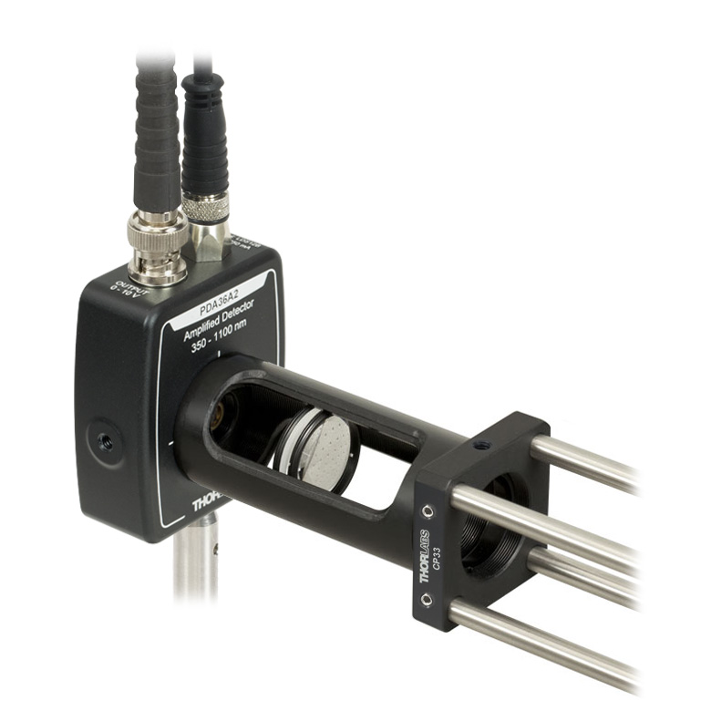
Figure 3.5 30 mmケージシステム内のSM1レンズチューブに接続されたPDAフォトディテクタ
Click to Enlarge
Figure 3.6 SM1外ネジで30 mmケージシステムに接続されたPDAフォトディテクタ
FPDシリーズディテクタ
FPDシリーズディテクタの各筐体の底面には、ポスト取付け用のM4タップ穴が1つ付いています。電源用コネクタと出力用SMAコネクタは、筐体の側面に付いています。このSMAコネクタは、入力インピーダンス50 Ωのモニタリングデバイス(オシロスコープやRFスペクトラムアナライザなど)に接続してご利用いただけます。
| Table 3.8 Housing Features | |||||
|---|---|---|---|---|---|
| Detectors | Housing Drawing (Click Icon for Details) | Mounting Taps | SM Thread Compatibility | Dimensions | Output Connector |
| PDA/PDF Fixed Gain | |||||
| PDA8A2, PDA10A2 |  | Two Universal Taps for 8-32 and M4 | Internal SM05 (0.535"-40) External SM1 (1.035"-40) | 1.96" x 0.89" x 2.79" (49.8 mm x 22.5 mm x 70.9 mm) | BNC |
| PDF10A2 |  | Two Universal Taps for 8-32 and M4 | 1.96" x 0.89" x 2.79" (49.8 mm x 22.5 mm x 70.9 mm) | ||
| PDA015A2 |  | Two Universal Taps for 8-32 and M4 | 1.96" x 0.89" x 2.79" (49.8 mm x 22.5 mm x 70.9 mm) | ||
| PDA10X2 |  | Two Universal Taps for 8-32 and M4 | 1.96" x 0.89" x 2.79" (49.8 mm x 22.5 mm x 70.9 mm) | ||
| FPD Fixed Gain | |||||
| FPD510-FS-VIS, FPD610-FS-VIS | 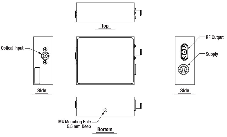 | One M4 Tap | N/A | 2.36" x 0.79" x 1.97" (60.0 mm x 20.0 mm x 50.0 mm) | SMA |
| PDA Switchable Gain | |||||
| PDA36A2, PDA100A2 |  | Two Universal Taps for 8-32 and M4 | Internal SM05 (0.535"-40) External SM1 (1.035"-40) | 2.07" x 0.89" x 2.79" (52.5 mm x 22.5 mm x 70.9 mm) | BNC |
| PDA20X2 |  | Two Universal Taps for 8-32 and M4 | Internal SM05 (0.535"-40) External SM1 (1.035"-40) | 2.09" x 0.89" x 2.79" (53.0 mm x 22.5 mm x 70.9 mm) | BNC |
| FPD Switchable Gain | |||||
| FPD310-FS-VIS | 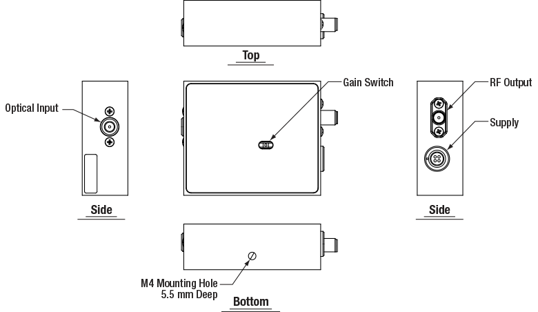 | One M4 Tap | N/A | 2.36" x 0.79" x 1.97" (60.0 mm x 20.0 mm x 50.0 mm) | SMA |
| PDA Switchable Gain USB DAQ | |||||
| PDA36AU |  | Two Universal Taps for 8-32 and M4 | Internal SM05 (0.535"-40) External SM1 (1.035"-40) | 2.65" x 0.89" x 1.96" (67.4 mm x 22.5 mm x 49.8 mm) | USB Type |
PDAおよびPDFシリーズディテクタ(型番PDA36AUを除く)
オス型(電源ケーブル)
メス型電源コネクタ(フォトディテクタ)
FPDシリーズディテクタ
メス型(電源ケーブル)
オス型電源コネクタ(フォトディテクタ)
PDAソフトウェア
バージョン1.0.0
下のSoftwareをクリックするとPDA制御ソフトウェアをダウンロードできます。

利得切り替え型USB DAQディテクタPDA36AU用ソフトウェア
PDA制御ソフトウェア:仮想2チャンネルオシロスコープ
PDAソフトウェアはディテクタPDA36AU用に設計されています。このソフトウェアは、ディテクタからのデータおよびディテクタへのアナログ入力信号を、仮想2チャンネルオシロスコープとして実時間(Live)表示するほかに、信号の記録・保存とその再生表示ができます。ソフトウェアはオシロスコープに共通する多くの一般的な機能を備えており、例えば両チャンネルの時間軸・電圧軸のズームおよび中心位置の選択、水平および垂直方向のドラッグ可能なカーソル、残像表示とスムージング表示のオプション、データ取得のための調整可能な時間・電圧・トリガの設定、信号の統計処理、データおよび画面のエクスポートなどの機能を有します。デバイスの利得は、このソフトウェア内で0 dB~70 dBの間を8段階(10 dB刻み)で設定できます。
PDA制御ソフトウェアの操作モード
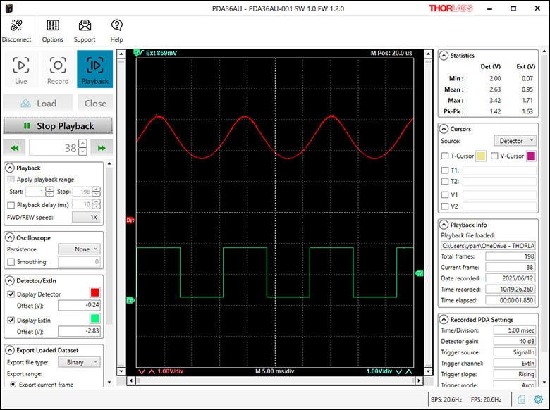
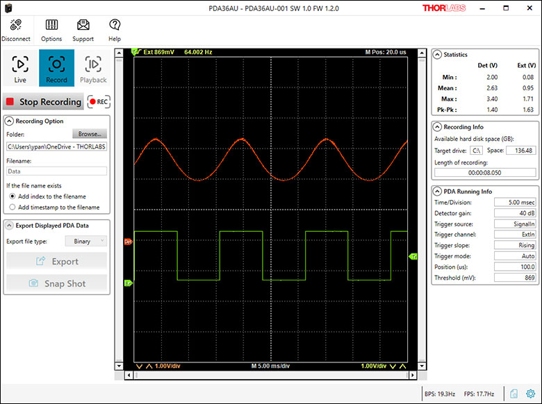
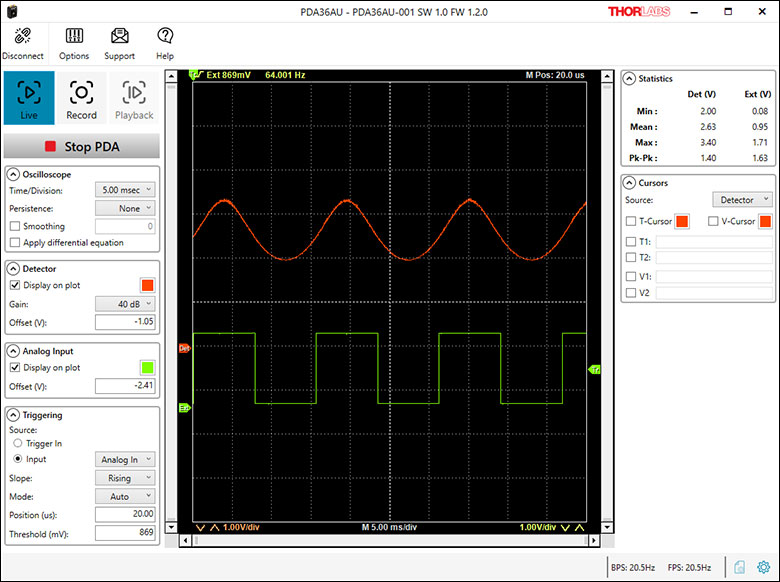
Figure 5.1、5.2、5.3は、ディテクタPDA36AUをライブモード、記録モード、および再生モードで使用したときのPDAソフトウェアの例を示しており、脚注にそれぞれの要約が記載されています。詳細はソフトウェアマニュアルをご参照ください。
Click to Enlarge
Figure 5.3 再生(Playback)モード
再生モードでは、記録モードで事前に保存したデータファイルを、仮想2チャンネルオシロスコープで再生表示できます。再生速度の選択、残像表示とスムージング表示の設定、2チャンネルの表示設定なども可能です。このモードではドラッグ可能なカーソルも使用できます。ファイル情報、記録の設定、2チャンネルの信号の統計量も表示されます。
Click to Enlarge
Figure 5.2 記録(Record)モード
記録モードでは、ライブモードで選択した取得設定を使用して、ディテクタおよびアナログ入力の信号データを制御用PC上のファイルに記録することができます。そのファイルの保存先フォルダを選択できるほか、表示データをファイルにエクスポートしたり、現在の仮想オシロスコープの表示のスナップショットを保存したりすることもできます。
Click to Enlarge
Figure 5.1 ライブ(Live)モード
ライブモードでは、デバイスPDA36AUを動作させるとともに、ディテクタ信号とアナログ入力信号を仮想2チャンネルオシロスコープとして連続的にストリーミング表示します。オシロスコープとしての設定、ディテクタおよびアナログ入力の設定、トリガ設定、およびドラッグ可能なカーソルについては、このソフトウェア内で調整できます。このモードでは両チャンネルの信号の統計値が表示されます。
フォトダイオードのチュートリアル
動作原理
接合型フォトダイオードは、通常の信号ダイオードと似た動作をする部品ですが、接合半導体の空乏層が光を吸収すると、光電流を生成する性質があります。フォトダイオードは、高速なリニアデバイスで、高い量子効率を達成し、様々な用途で利用することが可能です。
入射光の強度に応じた、出力電流レベルと受光感度を正確に把握することが必要とされます。Figure 100Aは、接合型フォトダイオードのモデル図で、基本的な部品要素が図示されており、フォトダイオードの動作原理が説明されています。
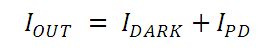
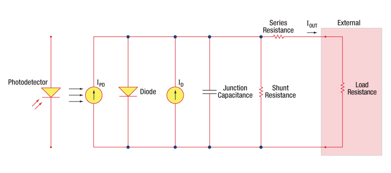
Figure 100A フォトダイオードの概略図
フォトダイオード関連用語
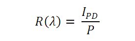
受光感度
フォトダイオードの受光感度は、規定の波長における、生成光電流 (IPD)と入射光パワー(P)の比であると定義できます。
Photoconductiveモード(光導電モード)とPhotovoltaicモード(光起電力モード)
フォトダイオードは、Photoconductiveモード(逆バイアス) またはPhotovoltaicモード(ゼロバイアス)で動作できます。 モードの選択は、使用用途で求められる速度と、許容される暗電流(漏れ電流)の量で決まります。
Photoconductiveモード(光導電モード)
Photoconductiveモードでは、逆バイアスが印加されますが、これが当社のDETシリーズディテクタの基本です。回路で測定できる電流量はフォトダイオードに照射される光の量を反映します。つまり、測定される出力電流は、入射される光パワーに対しリニアに比例します。逆バイアスを印加すると、空乏層を広げて反応領域が広くなるため、接合容量が小さくなり、良好な線形応答が得られます。このような動作条件下では、暗電流が大きくなりがちですが、フォトダイオードの種類を選ぶことで、暗電流を低減することもできます。(注:当社のDETディテクタは逆バイアスで、順方向バイアスでは動作できません。)
Photovoltaicモード(光起電力モード)
Photovoltaicモードでは、フォトダイオードはゼロバイアスで使用されます。デバイスからの電流の流れが制限されると電位が上昇します。このモードでは光起電力効果が引き起こされますが、これが太陽電池の基本です。Photovoltaicモードでは、暗電流は小さくなります。
暗電流
暗電流とは、フォトダイオードにバイアス電圧が付加されている時に流れる漏れ電流です。Photoconductiveモードで使用する場合に暗電流の値は高くなりがちで、温度の影響も受けます。 暗電流は、温度が10°C上昇するごとに約2倍となり、シャント抵抗は6°C の上昇に伴い倍になります。高いバイアスを付加すれば、接合容量は小さくなりますが、暗電流の量は増大してしまいます。
暗電流の量はフォトダイオードの材料や検出部の寸法によっても左右されます。ゲルマニウム製のデバイスでは暗電流は高くなり、それと比較するとシリコン製のデバイスは一般的には低い暗電流となります。Table 100Bではいくつかのフォトダイオードに使用される材料の暗電流の量と共に、速度、感度とコストを比較しています。
| Table 100B Photodiode Materials | ||||
|---|---|---|---|---|
| Material | Dark Current | Speed | Spectral Range | Cost |
| Silicon (Si) | Low | High Speed | Visible to NIR | Low |
| Black Silicon (B-Si) | Low | Medium Speeda | Visible to NIR | Moderate |
| Germanium (Ge) | High | Low Speed | NIR | Low |
| Indium Gallium Arsenide (InGaAs) | Low | High Speed | NIR | Moderate |
| Indium Arsenide Antimonide (InAsSb) | High | Low Speed | NIR to MIR | High |
| Extended Range Indium Gallium Arsenide (InGaAs) | High | High Speed | NIR | High |
| Mercury Cadmium Telluride (MCT, HgCdTe) | High | Low Speed | NIR to MIR | High |
接合容量
接合容量(Cj)は、フォトダイオードの帯域幅と応答特性に大きな影響を与えるので、フォトダイオードの重要な特性となります。ダイオードの面積が大きいと、接合容量が大きくなり、電荷容量は大きくなります。逆バイアスの用途では、接合部の空乏層が大きくなるので、接合容量が小さくなり、応答速度が速くなります。
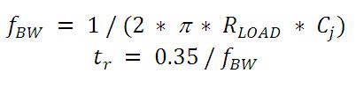
帯域幅と応答性
負荷抵抗とフォトディテクタの接合容量により帯域幅が制限されます。最善の周波数応答を得るには、50 Ωの終端装置を50 Ωの同軸ケーブルと併用します。接合容量(Cj)と負荷抵抗値(RLOAD)により、帯域幅(fBW)と立ち上がり時間応答(tr)の概算値が得られます。
雑音等価電力
雑音等価電力(NEP:Noise Equivalent Power)とは、出力帯域幅1 Hzでの信号対雑音比(SNR)が1になる入力信号のパワーです。NEPによって、ディテクタが低レベルの光を検知する能力を知ることができるので、この数値は便利です。一般には、NEPはディテクタの検出部の面積増加に伴って大きくなり、下記の数式で求めることができます。

この数式において、S/Nは信号対雑音比、Δf はノイズの帯域幅で、入射エネルギ単位はW/cm2となっています。詳細は、当社のホワイトペーパー「NEP – Noise Equivalent Power」をご覧ください。
終端抵抗
オシロスコープでの測定を可能にするためには、生成された光電流を電圧(VOUT)に変換する必要がありますが、負荷抵抗を用いて電圧変換します。
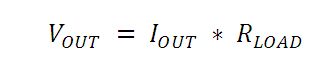
フォトダイオードの種類によっては、負荷抵抗が応答速度に影響を与える場合があります。最大帯域幅を得るには、50 Ωの同軸ケーブルを使用して、ケーブルの反対側の終端部で50 Ωの終端抵抗器の使用を推奨しています。このようにすることで、ケーブルの特性インピーダンスとマッチングできて共鳴が最小化できます。帯域幅が重要ではない特性の場合は、RLOADを増大させることで、所定の光レベルに対して電圧を大きくすることができます。終端部が不整合の場合、同軸ケーブルの長さが応答特性に対して大きな影響を与えます。したがってケーブルはできるだけ短くしておくことが推奨されます。
シャント抵抗
シャント抵抗は、ゼロバイアスフォトダイオード接合の抵抗を表します。理想的なフォトダイオードでは、シャント抵抗は無限大となりますが、実際の数値はフォトダイオードの材料の種類によって、10Ωのレベルから 数千MΩの範囲となる場合があります。例えばInGaAsディテクタのシャント抵抗は、10 MΩのレベルですが、GeディテクタはkΩのレベルです。このことは、フォトダイオードのノイズ電流に大きく影響を与える可能性があります。しかしながらほとんどの用途では、ある程度高い抵抗値であればその影響は小さく、無視できる程度です。
直列抵抗
直列抵抗は半導体材料の抵抗値で、この低い抵抗値は、通常は無視できる程度です。直列抵抗は、フォトダイオードの接触接続部とワイヤ接続部で発生し、ゼロバイアスの条件下でのフォトダイオードのリニアリティの主な決定要因になります。
一般的な動作回路
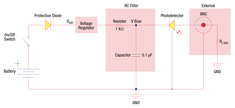
Figure 100C 逆バイアス回路(DETシリーズディテクタ)
Figure 100Cの回路はDETシリーズのディテクタをモデル化したものです。ディテクタは、入射光に対して線形の応答を得るために逆バイアス状態になっています。ここで生成された光電流の量は、入射光と波長に依存し、負荷抵抗を出力端子に接続すると、オシロスコープでモニタリングできます。RCフィルタの機能は、出力に雑音を載せてしまう可能性のある供給電力からの高周波雑音のフィルタリングです。

Figure 100D 増幅ディテクタ回路
高利得用途でアンプとともにフォトディテクタを使用できます。動作時には、PhotovoltaicモードまたはPhotoconductiveモードのいずれも選択可能です。このアクティブ回路はいくつかの利点があります。
- Photovoltaicモード:オペアンプで、点Aと点Bの電位が同じに維持されているので、フォトダイオードでは回路全体では0 Vに保たれています。このことで暗電流は発生しなくなります。
- Photoconductiveモード: フォトダイオードは逆バイアス状態であるので、接合容量を低下させ、帯域幅の状態を改善します。ディテクタの利得は、フィードバック素子(Rf)に依存します。ディテクタの帯域幅は、下記の数式で計算することができます。
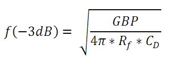
GBPが利得帯域幅積で、CDは接合容量と増幅器の静電容量の和です。
チョッパ入力周波数の影響
光導電信号は時定数の応答限界までは一定となりますが、PbS、 PbSe、HgCdTe (MCT)、InAsSbなどのディテクタにおいては、1/fゆらぎ(チョッパ入力周波数が大きいほどゆらぎは小さくなる)を持つため、低い周波数の入力の場合は影響が大きくなります。
低いチョッパ入力周波数の場合は、ディテクタの受光感度は小さくなります。周波数応答や検出性能は下記の条件の場合において最大となります。
![]()
Table 99Aは当社のPDA、PDFならびにDETディテクタの旧製品と現製品の一覧です。
| Table 99A Previous Generation Cross Reference of PDA and DET Detectors | |||||
|---|---|---|---|---|---|
| Wavelength | Material | Biased Detector | Amplified Detector | ||
| Current Generation | Previous Generation | Current Generation | Previous Generation | ||
| 200 - 1100 nm | Si | DET10A2 | DET10A(/M) | PDA10A2 | PDA10A(-EC) |
| 320 - 1000 nm | Si | - | - | PDA8A2 | PDA8A |
| 400 - 1000 nm | Si | - | - | PDA015A2 | PDA015A(/M) |
| 320 - 1100 nm | Si | DET100A2 | DET100A(/M)a | PDA100A2 | PDA100A(-EC)b |
| Si | - | - | PDF10A2 | PDF10A(/M) | |
| 350 - 1100 nm | Si | DET36A2 | DET36A(/M) | PDA36A2 | PDA36A(-EC) |
| 500 - 1700 nm | InGaAs | DET10N2 | DET10N(/M) | - | - |
| 800 - 1700 nm | InGaAs | DET20C2 | DET20C(/M) | PDA20CS2 | PDA20CS(-EC) |
| - | - | PDA05CF2 | PDA10CF(-EC) | ||
| - | - | PDA015C2 | PDA015C(/M) | ||
| - | - | PDF10C2 | PDF10C(/M) | ||
| - | - | PDA20C2 | PDA20C(/M) | ||
| 800 - 1800 nm | Ge | DET30B2 | DET30B(/M) | PDA30B2 | PDA30B(-EC) |
| DET50B2 | DET50B(/M) | PDA50B2 | PDA50B(-EC) | ||
| 900 - 1700 nm | InGaAs | DET10C2 | DET10C(/M) | PDA10CS2 | PDA10CS(-EC) |
| 900 - 2600 nm | InGaAs | DET05D2 | DET05D(/M)c | PDA10D2 | PDA10D(-EC)c |
| DET10D2 | DET10D(/M)c | - | - | ||
パルスレーザ:パワーとエネルギーの計算

パルスレーザからの放射光が、使用するデバイスや用途に適合するかどうかを判断する上で、レーザの製造元から提供されていないパラメータを参照しなければならない場合があります。このような場合、一般には入手可能な情報から必要なパラメータを算出することが可能です。次のような場合を含めて、必要な結果を得るには、ピークパルスパワー、平均パワー、パルスエネルギ、その他の関連するパラメータを必要とすることがあります。
- 生物試料を損傷させないように保護する
- フォトディテクタなどのセンサにダメージを与えることなくパルスレーザ光を測定する
- 物質内で蛍光や非線形効果を得るために励起を行う
パルスレーザ光のパラメータはFigure 170AおよびTable 170Bに示します。参照用として、計算式の一覧を以下に示します。資料を ダウンロードしていただくと、これらの計算式のほかに、パルスレーザ光の概要、異なるパラメータ間の関係性、および計算式の適用例がご覧いただけます。
計算式 | ||||
 | 、 |  | ||
 | ||||
 | ||||
 | ||||
平均パワーから算出するピークパワー、ピークパワーから算出する平均パワー : | ||||
 | 、 |  | ||
| 平均パワーおよびデューティーサイクルから算出するピークパワー*: | ||||
 | *デューティーサイクル( ) はレーザのパルス光が放射されている時間の割合です。 ) はレーザのパルス光が放射されている時間の割合です。 | |||
Click to Enlarge
Figure 170A パルスレーザ光の特性を記述するためのパラメータを、上のグラフとTable 170Bに示します。パルスエネルギ (E)は、パルス曲線の下側の黄色の領域の面積に対応します。このパルスエネルギは斜線で表された領域の面積とも一致します。
| Table 170B パルスのパラメータ | |||||
|---|---|---|---|---|---|
| パラメータ | シンボル | 単位 | 説明 | ||
| パルスエネルギ | E | ジュール[J] | レーザの1周期中に放射される1パルスの全放射エネルギ。 パルスエネルギはグラフの黄色の領域の面積に等しく、 これは斜線部分の面積とも一致します。 | ||
| 周期 | Δt | 秒 [s] | 1つのパルスの開始から次のパルスの開始までの時間 | ||
| 平均パワー | Pavg | ワット[W] | パルスとして放射されたエネルギが、1周期にわたって 均一に広がっていたと仮定したときの、 光パワーの大きさ(光パワー軸上の高さ) | ||
| 瞬時パワー | P | ワット[W] | 特定の時点における光パワー | ||
| ピークパワー | Ppeak | ワット [W] | レーザから出力される最大の瞬時パワー | ||
| パルス幅 |  | 秒 [s] | パルスの開始から終了までの時間。一般的にはパルス形状の 半値全幅(FWHM)を基準にしています。 パルス持続時間とも呼ばれます。 | ||
| 繰り返し周波数 | frep | ヘルツ [Hz] | パルス光が放射される頻度を周波数で表示した量。 周期とは逆数の関係です。 | ||
計算例
下記のパルスレーザ光を測定するのに、最大入力ピークパワーが75 mW
のディテクタを使用するのは安全かどうかを計算してみます。
- 平均パワー: 1 mW
- 繰り返し周波数: 85 MHz
- パルス幅: 10 fs
1パルスあたりのエネルギは、

と低いようですが、ピークパワーは、

となります。このピークパワーはディテクタの
最大入力ピークパワーよりも5桁ほど大きく、
従って、上記のパルスレーザ光を測定するのに
このディテクタを使用するのは安全ではありません。
| Posted Comments: | |
Michele Epis
(posted 2025-09-16 08:24:28.237) Does the PDA100A2 photdiode come with a factory calibration certificate or test report? ksosnowski
(posted 2025-09-16 11:03:09.0) Hello Michele and thanks for reaching out to us. The photodiodes in the PDA series are not calibrated for spectral responsivity during our production process. Each assembly is tested individually to ensure the device meets our specifications however these are not serialized and they do not ship with a report. Our S120C sensor is an off the shelf alternative for PDA100A2 that comes with a spectral calibration. I have reached out directly to discuss your application in further detail. Zeyan Zhang
(posted 2025-08-25 10:17:06.407) Hello. Can I install a power amplifier from Mini-Circuits at the output end of PDA10A2? ksosnowski
(posted 2025-08-25 10:10:46.0) Hello Zeyan, thanks for reaching out to us. The PDA10A2 produces an amplified voltage output however it is possible to use additional voltage amplification on the signal. This can be useful if the PDA output signal is above the 1.5mVrms typical noise floor of this detector but too small to trigger your measurement device's threshold. For optimum performance, the PDA10A2 output should be connected to a device with 50 Ohm input impedance. I have reached out directly to discuss your application in further detail. 国智 许
(posted 2025-04-23 08:06:50.093) For NIR wavelengths, the rise time of the photodiode element will become slower which may limit the effective bandwidth of the amplified detector.What are the specific reasons for this phenomenon. ksosnowski
(posted 2025-04-23 10:10:37.0) Hello, thanks for reaching out to us. The RC time constant is the limiting factor in time response of most photodiodes. In larger photodiodes, the relatively higher total sheet resistance leads to slower diffusion effects in the signal generated by NIR photons. This is because NIR photons can also absorb outside the biased layer, where there is no electric field to pull these into the measurement. The slow diffusion time through the material leads to a time constant that is no longer dominated by RC effects. This effect has only been noticeable in large area silicon photodiodes, and only above 800nm. I have reached out directly to discuss your application in further detail. Luis Soares
(posted 2025-04-10 14:05:48.39) I would like to know what low-intensity light source options you offer with this product. ksosnowski
(posted 2025-04-23 11:52:42.0) Hello Luis, thanks for reaching out to us. We offer a variety of stabilized light sources depending on your exact requirements. Some examples to consider are our SLS201L broadband lamp or HRS015B stabilized HeNe. I have reached out directly to discuss your application in further detail. Dogan Sinar
(posted 2025-04-01 13:33:51.147) Hi,
What is the angle of acceptance for the incoming light for the PDA100A2?
Could we use this detector to observe background light levels in the environment or do we need a normal AOI? ksosnowski
(posted 2025-04-01 04:42:00.0) Hello Dogan, thanks for reaching out to us. As there is no lens in this detector we do not specify angle of acceptance or NA. PDA100A2 has a wide aperture and detector area so it is possible to couple light in from a variety of angles. Higher angles can have a small impact on the response due to difference in reflection and absorption effects and at very high angles the housing will block some of the active sensor area. A condenser lens can be helpful for coupling in divergent sources but if the signal is coming from all directions then there will naturally be high loss. We specify the noise floor for each gain setting on the detector which you would need to overcome in order to resolve the background light signal. The large aperture size, broad response range of silicon, and broad power range due to switchable gain amplifier makes the PDA100A2 a very common starting point for optic sensors if the amount of light is previously unclear. I have reached out directly to discuss your application further. Alex Tupchenko
(posted 2025-03-27 16:42:03.3) Hi, could you pick up a kit that includes an avalanche photodector and all the necessary optical components for the previously described tasks? ksosnowski
(posted 2025-04-03 12:28:43.0) Hello Alex, thanks for reaching back out to us. I have contacted you directly to discuss the best selections for your application, as well as best practices to utilize these devices. Alex Tupchenko
(posted 2025-03-24 17:54:12.767) Hello, I am preparing a project for students, as part of the project I am developing a method for determining the saturation pressure of liquids using the light scattering method. The experimental setup includes a closed vessel with the liquid under study, into which a measuring sensor is introduced through a small sapphire window.
The essence of the method is as follows: with a gradual decrease in pressure in the system, gas bubbles are released from the solution. The moment of cavitation onset is determined by the change in the optical signal passing through the liquid.
At the moment, I have purchased the following equipment
ThorLabs RP22 optical sensor
M850F3 radiation source
T-Cube LED Driver LEDD1B driver
The main task is to select additional components of the optical system to improve the accuracy of measurements. In particular, it is required:
Select a suitable photodetector
Determine the need to use an optical isolator
Please share your recommendations on the configuration. ksosnowski
(posted 2025-03-25 11:43:08.0) Hello Alex, thanks for reaching out to us. Isolators would not be necessary for an LED source as they are not sensitive to optic reflections. Scattering results in high losses, so a high gain and/or low NEP detector may be necessary to see your signal. Depending on the bandwidth needed to see the rise and fall of your signal, this can potentially limit the suitable detectors. If your amount of optic signal is completely unknown, PDA100A2 may be a good starting point as the switchable gain feature allows use of a wide range of input powers. If a higher gain-bandwidth product or lower noise is required than what is covered by our PDA series, then an avalanche photodetector may be worth considering. The large sensor area of PDA100A2 also makes fiber coupling as trivial by using a mechanical adapter plate. I have reached out directly to discuss your application further. user
(posted 2025-03-13 07:52:40.0) Hello,
I am looking to measure the output pulse width of an Nd:YAG laser medical device. I would like to connect a photodetector to an oscilloscope to measure the laser pulse width.
The specifications of the laser I intend to measure are as follows:
Wavelength: 1064 nm
Maximum Energy: 500 mJ
Maximum Frequency: 10 Hz
Pulse Duration: 300 ps
Would it be possible to measure a 300 ps pulse width using the PDA10A2 photodetector? If not, could you kindly recommend a suitable photodetector capable of measuring pulse widths in the picosecond range?
Additionally, when measuring a 300 ps pulse width, I understand that a high-bandwidth photodetector is required. Could you also advise on the appropriate oscilloscope bandwidth needed for accurate measurement?
I would greatly appreciate any insights or recommendations you can provide.
Thank you in advance for your support. ksosnowski
(posted 2025-03-13 03:15:35.0) Hello, thanks for reaching out to us. The rise/fall time of the detector and oscilloscope must be faster than the optic pulse's rise/fall in order to prevent simply measuring the time limited response of the electronics. A rise time <100ps would be necessary to preserve a 300ps sinusoidal pulse period. PDA10A2 is not fast enough for such purposes, and while the sensor responsivity is low at 1064nm for this model, the high power of this laser will require significant attenuation with any photodiode to prevent saturation and damage. Our DET08 series may be an option to use here. Faster photodiodes tend to have a much smaller active area so alignment becomes critical to performance with DET08 series. I have reached out directly to discuss your application in further detail. user
(posted 2025-02-06 22:17:00.74) Hi, I am interested in PDA100A2 to use for my kid science project, I stumbled upon your product while researching for the items I needed to showcase a Glow worm attack or lamphone scenario. I had attended electronics tech course way back in the late 80's and have scant idea with it. I have an old telescope I could use for the project but have no idea what other equipment I needed to convert the signal from the pda100a2 into a digital signal before I plugged it in my laptop and use apps to show the result. cdolbashian
(posted 2025-02-14 04:10:27.0) Thank you for reaching out to us with this inquiry! I have contacted you directly to ask a few clarifying questions, as well as share some ideas regarding your application. Yuchen Xiang
(posted 2024-07-04 10:41:47.623) Hi there,
I currently have a PDA10A2 for some ultrafast imaging experiment that we are hoping to do. I note that the bandwidth of which can only be either 20 or 100 MHz, is there a way to access slower bandwidth? (using NI hardware and controlling from Matlab/Python). We would also be interested in purchasing a PDA100A2 for the larger detector area, so also wanted to check whether the bandwidth is tunable there.
Thanks in advance! ksosnowski
(posted 2024-07-09 12:50:52.0) Hello Yuchen, thanks for reaching out to Thorlabs. The bandwidth on our PDA series amplifier detectors is fixed by the photodiode and amplifier gain used in each model. With the switchable gain models you will see a lower bandwidth at higher gain values. However you could use a lowpass filter directly on the output perhaps like our coaxial filter EF526. You could also consider using a DET10A2 which has no amplifier but then a different termination resistance can be used to directly effect the gain and bandwidth. At higher gains you will expect lower bandwidths and with the DET series the termination resistance directly effects the RC time constant and lowpass cutoff frequency of the detector which we call the bandwidth. Our VT2 termination resistor can be a helpful tool for switching the gain/bandwidth of a detector like DET10A2. I have reached out directly to discuss this application in further detail. sukhyun CHOI
(posted 2024-03-06 11:35:35.973) currently i have PDA100A-EC old model.
Is there any example to get data with Labview? ksosnowski
(posted 2024-03-06 12:12:12.0) Hello Sukhyun, thanks for reaching out to Thorlabs. The PDA detector series have amplified analog voltage outputs and do not include any analog to digital converter (ADC). For use in Labview, typically a Data Acquisition card (DAQ) will be used to read the output voltage to a PC. The choice of DAQ often depends on things like the number of channels, bandwidth, and sample rate required in your setup. National Instruments has many guides on setting up a voltage measurement with the NI-DAQmx package. There is not any specific DAQ or ADC that we have at this time for digitizing the measurements. With our calibrated power meter and consoles systems like PM100D, those have built-in amplifier and ADC and provide a digital measurement which can be interfaced to Labview with our Optical Power Meter SDK. However our Calibrated Power Meter systems use sensors like our S120C and will not interface directly with the purely analog PDA100A2. I have reached out directly to discuss this application further. Abhirami Murugavel
(posted 2024-01-24 11:07:43.487) Respected Sir/Madam,
We bought this product long back and now we are facing some problem. Can you calibrate or rectify it? Is there anything we can do to rectify it? ksosnowski
(posted 2024-01-24 10:13:28.0) Hello, thanks for reaching out to Thorlabs. We do not calibrate this series of detectors however depending on the issue we may be able to fix the item. For issues like this I recommend reaching out directly to techsupport@thorlabs.com. I have reached out to discuss your application further. Zhang Yao
(posted 2023-06-17 17:21:33.707) What is the maximum input optical power PDA10A2 can withstand? ksosnowski
(posted 2023-06-20 11:30:21.0) Thanks for reaching out to Thorlabs. PDA10A2 uses our FDS010 photodiode which has max photocurrent of 5mA. You should also stay below saturation which will occur at 10V in HiZ or 5V in 50 Ohm measurements. The optical power at which this occurs depends on the gain and the responsivity at your wavelength. Due to the wide responsivity range, we do not list a single optical power limit as it does not well represent all scenarios. However for example in HiZ, PDA10A2 has ~0.45A/W @750nm, and 10kV/A gain, then the saturation power would be around 2mW. Saturation leads to nonlinear measurements and degrades the diode. Reducing optical power will bring you back below saturation, however prolonged saturation can increase the device noise permanently. feng xuehong
(posted 2022-09-27 20:25:39.207) good ksosnowski
(posted 2022-09-28 04:54:34.0) Hello Feng, thanks for reaching out to Thorlabs. Your positive feedback is very encouraging and we are glad to hear of your satisfaction. Christian M
(posted 2022-07-15 16:02:32.883) Greetings,
we noticed that the LDS12B power supply is quite bad for our coherence times, most likely through stray magnetic fields caused by it. Do you have any info on the spectral properties of its noise? Is it a switching power supply and if so, at what frequency does it switch?
Cheers cdolbashian
(posted 2022-07-26 02:44:51.0) Thank you for you inquiry regarding our product. To address the straightforward question, this is a linear supply. As far as the spectral distribution of the noise, we do not have this on hand. I have reached out to you to discuss potential approaches to acquiring these data! Paul Chen
(posted 2022-01-06 00:29:37.773) Hello Sir,
I'm Paul from UL Taiwen. I have few question need your support.
1.I saw the cost from your website is USD356.04. Does it correct?
2.PDA36A2 be listed on VESA AdaptiveSync spec. Because I couldn't find how to setup and use it to test in your user guide.
could you please share any document how to use it to test, such as how to test gray to gary.
3.Does PDA36A2 need "USB DAQ" to analysis data?
Looking forward your feedback.
thanks!! cdolbashian
(posted 2022-01-14 01:53:57.0) Thank you for contacting us Paul. I have contacted you directly to discuss your specific application. Bryan Zhu
(posted 2021-08-11 21:25:45.687) I am a memeber in Prof Cui's group of HKU. We want to obtain the real power of our White laser by PDA36-EC-Si Detector. Do you have the data of the responsitiity in a text file? Thanks very mych! Bryan Zhu
(posted 2021-08-11 21:18:51.83) I am a memeber in Prof Cui's group of HKU. We want to obtain the real power of our White laser. Do you have the data of the responsitiity in a text file? Thanks very mych! YLohia
(posted 2021-08-27 03:00:20.0) Hello, we have reached out to you directly with "typical" raw data for the component photodiode. These should not be taken as absolute responsivities due to production variations. Especially since there is an OP-amp in this device, converting a current output to a Voltage output. 明露 李
(posted 2021-08-09 16:42:11.66) 你好,我这边有一个贵公司的PDA36A2传感器,需要一个配套的采集卡,
请问贵公司可以推荐下型号吗?我在贵公司网站上没有发现 cdolbashian
(posted 2021-08-19 02:00:47.0) Thank you for contacting us here at Thorlabs. You asked the following question:
Hi, I have one of your PDA36A2 sensors and I need a matching capture card. Can you recommend a model number? I can't find it on your website.
Unfortunately, we do not carry these types of products. I have reached out to you directly to discuss other options. Fabrice Jaques
(posted 2021-01-13 06:20:38.493) question about electronic schematic of PDA100A2 :
in the drawing of manual.pdf, the photodetector is connected either to GND or "-V". Is it selectable ?
I'd like to get -12V on the anode to get higer current ...
Thank's for your answer
Best regards
Fabrice asundararaj
(posted 2021-01-19 11:12:13.0) Than you for contacting Thorlabs. No, the bias on the PDA is not selectable. Most PDA’s have some bias voltage that is chosen based on the photodiode installed. There are a few that do not have bias voltages so they would be anode GND instead. The bias on the detectors is part of the design of the detector and is chosen to maximize and match the performance to the amplifier. asundararaj
(posted 2021-01-19 11:12:13.0) Thank you for contacting Thorlabs. No, the bias on the PDA is not selectable. Most PDA’s have some bias voltage that is chosen based on the photodiode installed. There are a few that do not have bias voltages so they would be anode GND instead. The bias on the detectors is part of the design of the detector and is chosen to maximize and match the performance to the amplifier. Ramprakash Ananth
(posted 2020-11-12 21:09:11.02) Hi, I have PDA36A2 and works fine. I need to know the threshold of the laser power which can be withstand by this photodetector when operated at 0 dB gain and at high impedence setting. I am planning to use a 200 mW CW laser. If you suggest a neural density filter kindly recommend a suitable filter with the damage threshold value. asundararaj
(posted 2020-12-29 03:19:15.0) Thank you for contacting Thorlabs. We do not spec a damage threshold for our detectors. We recommend that the PDAs are not operated the beyond saturation which happens at a few mW. You can estimate the saturation power for a given wavelength and for max voltage (10 V for Hi-Z),using the following equation,
Maximum Optical Input (in W) * Responsivity (in A/W) * Transimpedance Gain (in V/A) = Bias Voltage (in V). You may need to attenuate your beam using an ND filter which can be found in this link - https://www.thorlabs.com/navigation.cfm?guide_id=2185 Yachel Ben Shalom
(posted 2020-10-01 08:15:42.267) We use in our setup the model PDA8A2.
In our setup all of the components work 24/7 even when no experiment runs. My question is if it is good for the photo-diode to be connected 24/7 or it will be better to turn it off by switch when no experiment runs? dpossin
(posted 2020-10-02 09:37:04.0) Dear Yachel,
Thank you for your feedback. In general the PDA8A2 should be suitable for long therm operation. However to switch off the detector when not in use could extend the lifetime. Stephen Yates
(posted 2020-08-10 22:26:39.457) If possible, what adapters would I need to mount the PDA10A2 to a standard 0.96" or 1.25" telescope eyepiece tube? asundararaj
(posted 2020-08-12 09:05:11.0) Thank you for contacting Thorlabs. The PDA10A2 has both an external SM1 and an internal SM05 threads, which can be used for mounting in addition to the mounting hole in the bottom. As for attaching to the telescope, you will require an adapter that will depend on the threads on the telescope. I have reached out to you via email to discuss this further. Mitchell Bierschenk
(posted 2020-07-24 16:39:37.86) I am trying to use the PDA10A2 to measure white to black transitions on an LCD but am unable to see any change on my oscilloscope that is terminated to 50 ohms. I can point my flashlight from my phone at the PDA10A2 and the oscilloscope will jump up to around 1V. Is the PDA10A2 not sensitive enough to measure my LCD or are there other devices or lenses that are capable of measuring lower? YLohia
(posted 2020-09-24 03:54:47.0) Thank you for contacting Thorlabs. The PDA can reliably detect powers down to a few µW. It is quite likely that you're not able to collect a sufficient amount of power from your LCD. That being said, you can use a higher impedance termination to see a higher signal for the same power incident (higher gain) on the detector. We had reached out to you directly at the time of your original posting to discuss this further. Steve Colavito
(posted 2020-02-13 14:25:12.413) The PDA100A2 that I have seems to have a step response with significant overshoot and ringing. I did not expect this with such a sensor. I'm not sure if there is something wrong with my detector. Is any information available on the step response of this photodetector? asundararaj
(posted 2020-02-21 08:29:38.0) Thank you for contacting Thorlabs. I have contacted you directly via email to troubleshoot. Everett Ramer
(posted 2019-11-13 15:34:08.7) My PDA10A2 gives an output voltage of -8mV with the lens cap on. Do I assume this is an offset voltage and add it to readings taken when the lens cap is removed? YLohia
(posted 2019-11-14 12:31:12.0) Hello, thank you for contacting Thorlabs. That is correct, this is just a DC offset voltage that comes from the tuning of the internal electronics/amplifier. The tolerance on this spec is +/-10 mV, so you can simply add the 8 mV factor to your readings. user
(posted 2019-11-12 19:16:32.63) Dear Mada or Sir,
I am considering a PDF10A photodetector to measure and calibrate a light source that has an average power of ~10pw, composed of 50ps pulses. The accuracy of the measurement is crucial in my application. Could you please let me know if this photo detector is available with NIST or NIST tractable calibration?
Additionally, what kind of uncertainties can I expect from this photodetector? is 2 or 3% achievable?
Best Regards, MKiess
(posted 2019-11-14 08:17:45.0) This is a response from Michael at Thorlabs. Thank you for the inquiry. The detector’s response is not NIST calibrated. If we consider the maximum conversion gain with regard to the deviation, it is 0.6 x 10^(12)V/W ±10%. If you want to resolve the ps pulses of your laser in time you should also note that the rise/fall time of the detector is 20ms and the bandwidth is DC-20Hz. We also have detectors with shorter rise/fall time and larger bandwidth. I contacted you directly to discuss your application and find the most suitable detector together with you. Kristof Reynkens
(posted 2019-06-27 05:04:48.54) I wondered if the FPD610-FS-VIS can be cooled and how the NEP would change with temperature. asundararaj
(posted 2019-08-01 01:20:00.0) Thank you for contacting Thorlabs. We expect the NEP to decrease with a decrease in temperature, but unfortunately, we do not have any data for the temperature dependence of NEP for this detector. As for the cooling of the detector, these do not have a built in cooling element. The photodiode itself is not optimized to be thermally coupled to the exterior mount. user
(posted 2019-05-17 11:46:03.53) What are the output impedances of PDA10A2 and PDA36A2? Also, can you provide a detailed frequency response for these devices? I need to know the bandwidth if I ask for 1% response flatness. asundararaj
(posted 2019-05-20 07:34:49.0) Thank you for contacting Thorlabs. The output impedance of PDA10A2 and PDA36A2 are 50 Ohms.
I have contacted you directly about the frequency responses for the two amplified photodetectors. Due to the inherent nature of the Si-Photodiode, the frequency response would not be flat over the entire bandwidth. Also, please note that the bandwidth and the frequency response of the PDA36A2 will depend on the gain setting. carlo.desanti
(posted 2018-12-18 15:38:26.053) Dear Thorlabs staff,
I need the responsivity data of the PDF10A outside the limits already reported in the website (i.e. above 1100nm and below 320 nm). Are you able to provide them? If not, even a guess based on data of other Si-based detectors would be helpful. swick
(posted 2019-01-11 03:39:26.0) This is a response from Sebastian at Thorlabs. Thank you for the inquiry.
For PDF10A we have no data about sensitivity outside 320 - 1100 nm.
Below 320 nm absorption of protection window gets significant and above 1100 nm absorption coefficient of active area decrease.
I contacted you directly for further discussion. john.w.easton
(posted 2018-12-04 11:51:56.953) I am a little confused by the "Hi-Z" references for higher (0-10 V) output on the PDA10A2. Just how high-Z is "hi-z"? I understand the 50-ohm resistor gives a 0-5V output, but what resistance is needed for 0-10V? Does the device internally compensate for higher impedences, or is there something in a voltage divider I'm missing? YLohia
(posted 2018-12-05 04:18:17.0) Hello, there is no discrete point of transition between 5V max output and 10V max output. This is entirely dependent on the scale factor due to the voltage divider mentioned in the manual. For example, if the load impedance used is 150 Ohms, the scale factor then becomes 150/(150 + 50) = 0.75, which means that the voltage output range will be 0 to 7.5V. The device does not internally compensate for impedance levels. yongqi.shi
(posted 2018-11-27 18:16:43.07) Dear sir, I'm using a PDA36A2 photodetector to measure a beam with power around 0.4mW. When I set to 0dB gain, the output voltage is exactly P*R(780nm)*Gain=140mV. Considering there is stub-style 50 ohm terminator connected, why I didn't see any voltage distribution (this scaling factor from manual) of output? YLohia
(posted 2018-12-27 04:04:24.0) Hello, thank you for contacting Thorlabs. The gain factor of 0.75 kV/A you used in the calculation already accounts for the 0.5 voltage distribution factor. We are working on making this information more clear in the manual. benjamin.franz
(posted 2018-05-07 15:37:59.407) Dear Thorlabs-Team,
We have issues opening the PDA10A2 .step file. It looks very buggy with intersecting planes and volumes. Do you have alternatives or a fixed model for us?
(Also, Parasolid does not work for us)
Best regards,
Ben YLohia
(posted 2018-05-09 08:03:49.0) Hi Ben, thank you for contacting Thorlabs. The .step and .sldprt files work for us using Solidworks Premium 2016 and eDrawings. I will reach out to you directly with a .igs file. florio
(posted 2018-01-05 14:06:15.767) Dear Thorlabs team,
in some of my applications, I calculated that the detector PDA100A will be exposed to a light power (at different wavelengths) up to 300 mW. Is there a filter I can buy to make valuable measurements in this range, without damaging the detector?
Thank you in advance.
Best regards,
Kevin nbayconich
(posted 2018-02-21 09:58:12.0) Thank you for contacting Thorlabs. The transimpedance amplifiers of these detectors will saturate before being damaged and at the lowest gain setting when using a 50 ohm terminating resistor the amplifier of the PDA100-EC will saturate at around 21.3mW. Since you have a 300mW source I suggest using a neutral density filter that has an optical density of at least OD 1.2 or higher, something like NE513B-A can be suitable. I'll reach out to you directly to discuss the damage thresholds of our ND filters. soshenko.v
(posted 2017-10-02 16:47:53.717) Hello thorlabs. I want to supply PDA100A from two Pb batteries. Could you provide me with partnumber of cable plug to fit PDA power input? tfrisch
(posted 2017-11-14 03:04:30.0) Hello, thank you for contacting Thorlabs. If you want to wire your own power supply, you can use PDA-C-72 which is lower down on this page. zif3ng.wu
(posted 2017-07-04 11:54:04.23) Hello, I am interested in buying either the PDA015A or PDA10A. My application is for optical wireless communications, thus I would like to have the flexibility of mounting different focusing lenses onto the front of the detector. Which products can you recommend for this purpose? tfrisch
(posted 2017-08-04 10:16:18.0) Hello, thank you for contacting Thorlabs. I will reach out to you directly to discuss your application, but likely a plano-convex lens just to collect light and focus it onto the detector would improve signal strength. tanmaybhwmk3
(posted 2017-06-09 22:54:49.703) In the safety guide, it is mentioned about the scale factor. And, after calculating maximum incident light intensity from that formula we got 22 mW for PDA100A-EC.
But, without scale-factor it is coming 10.7 mW.
Kindly give your valuable reply regarding which answer is correct. tfrisch
(posted 2017-06-26 10:11:56.0) Hello, thank you for contacting Thorlabs. There is not a maximum incident power spec for several reasons. One is that the responsivity is dependent on wavelength, so the power would change. Another is that saturation of the detector occurs before damage. I will reach out to you with more details on estimating these values given the Max Output Current (100mA) and the other details of your setup. christian.schuster
(posted 2017-06-09 14:06:41.517) Does the PDF10A has any coatings on the sensor area, such as an anti-reflective layer ? wskopalik
(posted 2017-06-13 05:18:30.0) This is a response from Wolfgang at Thorlabs. Thank you very much for your inquiry.
The photodiode in the PDF10A has a protective window made of borosilicate glass, but no anti-reflective coating.
I will contact you directly to provide further assistance. mebert
(posted 2017-05-17 22:22:25.577) Hi, can the voltage regulators on the PDA36A work with +/-15 V?
We have a +/-15 V distribution system and I would like to get rid of the bulky AC/DC converters provided with the units we have. nbayconich
(posted 2017-05-22 04:29:42.0) Thank you for contacting Thorlabs. The input voltage of the PDA36A must be kept at ±12V. Driving at 15V can damage the output drive when operating 50 ohm load. A Techsupport representative will contact you directly. jona.beysens
(posted 2017-01-18 09:19:54.95) Hi,
We have a PDA10A in our laboratory in Belgium and we measure strange values. In the data sheet, it is mentioned that the output voltage of the photodiode is in the range 0V->10V. However, if we connect the output of the PDA10 directly to an oscilloscope, we measure values of -180mV when there is almost no light. Can you help us out with this problem?
Best regards,
Jona Beysens tfrisch
(posted 2017-01-19 02:51:04.0) Hello Jona, thank you for contacting Thorlabs. I will reach out to you directly to troubleshoot your PDA10A. brian.markey
(posted 2016-12-01 11:09:02.007) Your tutorial indicates that these Si photodetectors are highly linear. Can you quantify the linearity and dynamic range? i.e. how linear and over what range? swick
(posted 2016-12-07 03:05:17.0) This is a response from Sebastian at Thorlabs. Thank you very much for your inquiry. The maximum output voltage swing of PDF10A is +10V. Saturation of the output will occur at optical input power greater than CW Saturation Power (16pW for PDF10A).
Saturation of the Photodiode will cause nonlinear behavior. ND filters can be used to reduce the optical power and extend the operation range.
The minimal detectable power, calculated from NEP at 960nm and SNR=1 , is 6fW. I have contacted you directly to provide further assistance. Ludovic.BERNARD
(posted 2016-07-18 09:31:07.223) Hello, I'm using the PDA36A-EC to detect light pulses from 1 to 10 µs.
I observe a charging time of 1.8 µs for the photodetector response signal and I was wondering if it was a normal value.
If not can it come from the photodetector?
Thank you. jlow
(posted 2016-07-18 10:52:36.0) Response from Jeremy at Thorlabs: The rise time is going to be dependent on the gain setting that you choose. Also, if the detector is saturated, the rise time will be longer than usual as well. We will contact you directly to troubleshoot this. kangsongbai83
(posted 2016-06-13 20:05:32.29) Hello,I have a PDA36A Si detector which does not work now. I wonder how to repair it? Should I just send it back to Thorlabs? I think it is under warranty but not very sure. besembeson
(posted 2016-06-15 10:52:17.0) Response from Bweh at Thorlabs USA: I have contacted you directly. goncharovv
(posted 2016-03-25 15:53:47.357) What is the maximum amount of optical power that the PDA36A and PDA100A can withstand before the damage occurs (not saturation). besembeson
(posted 2016-03-25 05:01:36.0) Response from Bweh at Thorlabs USA: You should keep the power below 100mW to prevent damage. For typical use, under 1mW is recommended to keep the detector in the linear regime as these are amplified detectors. liuhong_ayj
(posted 2015-03-31 16:39:31.477) I want to use PDA10A for detection of rapid fluorescence signals (60MHz)from organic dyes in cell membranes. this PDA10A can go to work? jlow
(posted 2015-03-31 01:17:33.0) Response from Jeremy at Thorlabs: We will have to get more information about your application before being able to recommend a specific detector. I will contact you directly about this. alaaeldin12
(posted 2014-10-16 15:17:43.007) Hello,
I want to ask about the output of the PDA10A detector.
What is the compatible power meter?
Please contact me via email. Thank you. jlow
(posted 2014-10-16 02:35:46.0) Response from Jeremy at Thorlabs: The PDA10A outputs a voltage signal but the detector's response is not NIST calibrated. We do offer power meter system which can be found at http://www.thorlabs.com/navigation.cfm?guide_id=37. I will contact you directly about our power meter system. adavies78
(posted 2014-10-08 09:36:17.2) Is there any certification that the responsivity is linear across intensity range?
i.e. is dV/dP the same for output in the 0-1V range as the 9-10? jlow
(posted 2014-10-08 04:04:38.0) Response from Jeremy at Thorlabs: The response of the detector is linear for output below the maximum voltage (10V with Hi-Z load). lesundak
(posted 2014-08-22 18:28:19.383) hello, I cannot obtain more than 0,45V output from my PDA8A. Under this value detector works good, but at 0,45V looks like it is saturated. What can be wrong? Thanks shallwig
(posted 2014-08-26 07:38:27.0) This is a response from Stefan at Thorlabs. Thank you very much for your inquiry. I am sorry that you face problems with the PDA8A. I will contact you directly to troubleshoot this problem. vkogotkov
(posted 2014-07-18 12:44:03.447) Dear Sirs, We would want to use one of your Amplified Photodetectors for detecting radiation of N2-laser. Beam characteristics: LengthxWidth-20x10mm, Pulse intensity-0,5 mJ, pulse duration-100ns. What Amp. Photodetector is best for our application? As I understand we'd need additional focusing and filtering components for this system... What can You advise? jlow
(posted 2014-08-01 01:49:35.0) Response from Jeremy at Thorlabs: There are a few details missing from your setup description. We will contact you directly to discuss about this. hha07
(posted 2014-03-28 17:31:22.757) The datasheet for the PDA8A/M specifies the output voltage for terminations of Hi-Z and 50 Ohm. I have an application where I'd like to connect the detector to a Mini-circuits mixer (tuf-3lh) which has an input impedance given by a coil connected to ground such that at DC the impedance is 0 Ohm. This will of course force the signal to 0 at DC. Will this damage the PDA8A/M detector by drawing to much current.
What is the output impedance of the PDA8A/M and how is it connected, in series or in parallel?
Regards,
Hans Harhoff Andersen. jvigroux
(posted 2014-04-14 05:01:57.0) A response from Julien at Thorlabs: Thank you for your inquiry! The connection to the coil will not damage the detector. This being said, one could of course use a coupling capacitance before the balun to achieve separation from the DC path. The output impedance is 47Ohms series. paul.hamilton
(posted 2013-09-06 17:49:33.61) I'm having a hard time reproducing the numbers in the manual of the PDA36A for the NEP. I would have assumed that NEP = Noise_rms / Sqrt(BW) / Gain / Responsivity, but when I put in these numbers I get a NEP more than an order magnitude higher. Am I doing something incorrectly? jlow
(posted 2013-09-11 14:38:00.0) Response from Jeremy at Thorlabs: You are correct that NEP = Vrms/(Gain*Responsivity*vbandwidth). The bandwidth used in the calculation is the bandwidth of the measuring system and not the bandwidth of the detector. yuby2010
(posted 2013-08-28 14:19:19.92) There is a response curve in the Manual of PDA10A,but I can't find the detail spectrum response data, the responsivity of each wavelength. Would you please give me this? sharrell
(posted 2013-08-29 16:35:00.0) Response from Sean at Thorlabs: Thank you for your feedback. I emailed you the data file directly, and we are in the process of adding the data for all of our Amplified Detectors directly to the website. leon.islas
(posted 2013-05-09 13:33:28.323) I am planing on using this PDA for detection of rapid (msec) fluorescence signals from organic dyes in cell membranes but I am not sure that about the sensitivity. Do you have any experience with this type of measurement (voltage clamp fluorometry) or can recommend references? jlow
(posted 2013-05-09 15:00:00.0) Response from Jeremy at Thorlabs: I will get in contact with you directly do discuss about the details in your experiments. lixx1878
(posted 2013-04-05 12:09:53.973) I have a question about PDA36A. I plan to do photoluminescence experiment with it under low temperature (>77K). Does PDA36A work at that range? Do you have a responsitivity curve for that? jlow
(posted 2013-04-08 09:52:00.0) Response from Jeremy at Thorlabs: The operating temperature for the PDA36A is 0-40°C. adamaller
(posted 2013-03-27 05:19:04.92) Why the maximum incident light intensity is not indicated clearly, please? cdaly
(posted 2013-04-02 16:04:00.0) Response from Chris at Thorlabs: Thank you for using our web feedback. The saturation point can be found by dividing the max voltage output for it's corresponding gain and responsivity. So for example with a 50Ohm resistance, the PDA8A can ouput up to 5V, dividing by 50kV/A and 0.5A/W (at peak responsivity), we end up with 64.3mW on the lowest gain setting. The same can be done for the other detectors as well. Each on the lowest settings, the PDA10A would be 2.22mW. The PDFF10A would be 2nW, the PDA36A and PDA100A would both be 10.3mW. adavies78
(posted 2013-03-15 09:07:24.04) I have a DC sensing application where i use 4 PDA36A detectors at the highest gain setting.
When I turn off the light source, there is a wide range of dark level--understandable for different chips. But some are negative. I don't understand why there would be negative dark signal unless an offset is built into the output...can you explain? jlow
(posted 2013-03-18 14:35:00.0) Response from Jeremy at Thorlabs: The negative value that you see is the amplifier offset, which can be negative (for PDA36A, the offset should be within ±10mV at 70dB gain). For the recently purchased PDA36A (after July 2012), and PDA100A (after October 2012), there is a way to adjust the amplifier offset. If you remove the back cover of the PDA, there is a trimmer potentiometer which sets the offset. You can set the offset to what your desire value by covering up, and then adjusting the offset at 70dB gain setting. sharrell
(posted 2012-12-06 15:58:00.0) Response from Sean at Thorlabs: Thank you for your feedback. For the PDA36A(-EC), the bandwidth at the 70 dB gain setting is 5 kHz. Complete specifications at each gain setting can be found on page 9 of the manual (http://www.thorlabs.com/Thorcat/13000/PDA36A-Manual.pdf). I have already updated the webpage to refer future customers to that location. We are in the process of developing a new website feature that will allow us to provide the complete set of specifications for detectors and other products in a more convinient way, and I will make sure that this page is one of the first to utilize the new feature. graham.naylor
(posted 2012-12-06 15:17:45.83) What is the bandwidth at full gain - it is not clear from the web site and I have an inkling that you reduce the bandwidth at higher gain.
thanks
Graham jjurado
(posted 2011-06-28 17:09:00.0) Response from Javier at Thorlabs to Veinardi.Suendo: Thank you very much for contacting us. Although it would be recommendable to place the FEL1200 filter at the input of the collimator, the structure of the setup you propose might work without the lens. The only concern is, of course, the space between the tip of the fiber and the lens. In principle, you could use the following path: Collimator-> Fiber-> SM1SMA Fiber Adapter-> Filter-> Detector. However, since the overall thickness of the filter is 6.3 mm, this added distance between the fiber and the active area of the detector, which is 1.1 mm x 1.1 mm, could cause some loss, since the output from the fiber will be divergent. You could perhaps use an aspheric lens pair to focus the output from the fiber onto the detector (link below), but this would add to the overall length and complexity of the setup. I will contact you directly to discuss this and other possibilities for your application.
Aspheric lens pairs: http://thorlabs.com/NewGroupPage9.cfm?ObjectGroup_ID=278
SM1SMA adapter: http://www.thorlabs.com/NewGroupPage9.cfm?ObjectGroup_ID=69&pn=SM1SMA#3182 Veinardi.Suendo
(posted 2011-06-28 15:59:21.0) Dear Sirs,
We planned to purchase your product (PDF10C/M) for our lab. in Indonesia. I believed that they have already launched the project. However, we need your assistance to connect this detector to optical fiber with SMA termination and a long wave pass filter (FEL1200). Would you mind telling us, which part is needed. Personally, I have in my mind this kind of setup:
(collimator)-->
(Optical Fiber)-->
(fiber adapter)-->
(SM1 tube)-->
(lens?)-->
(filter)-->
(detector).
Is it possible? Do we really need a lens in this case? Thank you very much for your assistance.
Yours Sincerely,
Dr. Veinardi Suendo Customer Email: Veinardi.Suendo@polytechnique.edu This customer would like to be contacted. jjurado
(posted 2011-04-20 09:11:00.0) Response from Javier at Thorlabs to last poster: Thank you very much for your feedback. We have updated the Overview tab in order to clarify the different transimpedance specs for these detectors. Please do not hesitate to contact us at techsupport@thorlabs.com if you have any further questions or comments. user
(posted 2011-04-19 17:21:14.0) Transimpedance gain for the PDF10A is mentioned in the Overview tab, but the wording seems to indicate that both this and the PDF10C share a common gain value. |
下表は、当社のフォトダイオードタイプのディテクタ、フォトコンダクティブ型ディテクタ、焦電ディテクタの一覧です。同一の列に記載されている型番の検出素子は同じです。
| Item #a | Housing Featuresb | Wavelength Range | Bandwidth Range | Rise Time | Gain | NEP | Typical Performance Graphs | Active Areac | Operating Temperature Range | Power Supply Included | |
|---|---|---|---|---|---|---|---|---|---|---|---|
| Hi-Z Load | 50 Ω Load | ||||||||||
| PDA10A2d |  | 2.3 ns | 10 kV/A | 5 kV/A | 29.2 pW/Hz1/2 | 0.8 mm2 (Ø1 mm)f | 10 to 50 °C | Yes | |||
| PDA8A2 |  | 320 - 1000 nm | DC - 50 MHz | 7 ns | 100 kV/A | 50 kV/A | 7.8 pW/Hz1/2 | 0.5 mm2 (Ø0.8 mm) | 10 to 50 °C | Yes | |
| PDF10A2 | | 320 - 1100 nm | DC - 20 Hz | 22 ms | 1 x 10⁹ kV/A | - | 1.2 mm2 | 10 to 50 °C | Yes | ||
| PDA015A2 | | 400 - 1000 nm | DC - 380 MHz | 1.0 ns | 50 kV/A | 25 kV/A | 36 pW/Hz1/2 | 0.018 mm2 (Ø150 µm) | 10 to 40 °C | Yes | |
| 400 - 1000 nm | DC - 250 MHz | 2 ns | - | 1.5 x 10⁵ Vpp/Wg 2.5 x 10⁴ Vpp/Wh | 6.0 pW/Hz1/2 | 0.13 mm2 (Ø0.4 mm) | 10 to 40 °C | Yes | |||
| FPD610-FS-VIS | 400 - 1000 nm | DC - 600 MHz | 1 ns | - | 2 x 10⁶ Vpp/Wg 2.5 x 10⁵ Vpp/Wh | 11.2 pW/Hz1/2 | 0.13 mm2 (Ø0.4 mm) | 10 to 40 °C | Yes | ||
| Item #a | Housing Featuresb | Wavelength Range | Bandwidth Rangec | Gain | Noise Equivalent Power (NEP)d | Typical Performance Graphs | Active Area (Click Link for Image) | Operating Temperature Range | Power Supply Included | |
|---|---|---|---|---|---|---|---|---|---|---|
| Hi-Z Load | 50 Ω Load | |||||||||
| PDA10X2e | | 240 - 1170 nm | DC - 21 MHz | 60 kV/A | 30 kV/A | 21.1 pW/Hz1/2 | 1 mm2 (1 mm x 1 mm) | 10 to 40 °C | Yes | |
| Item #a | Housing Featuresb | Wavelength Range | Bandwidth Rangec | Gain | Noise Equivalent Power (NEP)d | Typical Performance Graphs | Active Area (Click Link for Image) | Operating Temperature Range | Power Supply Included | |
|---|---|---|---|---|---|---|---|---|---|---|
| Hi-Z Load | 50 Ω Load | |||||||||
| PDA20X2e | | 240 - 1170 nm | DC - 11 MHzf | 1.51 kV/A - 4.75 MV/A | 0.75 kV/A - 2.38 MV/A | 3.27 - 60 pW/Hz1/2 | 4 mm2 (2 mm x 2 mm) | 10 to 40 °C | Yes | |
| Item #a | Housing Featuresb | Wavelength Range | Bandwidth Range | Gain | NEP | Typical Performance Graphs | Active Area (Click Link for Image) | Operating Temperature Range | Power Supply Included | |
|---|---|---|---|---|---|---|---|---|---|---|
| Hi-Z Load | 50 Ω Load | |||||||||
| PDA100A2c |  | 320 - 1100 nm | DC - 11 MHz | 1.51 kV/A - 4.75 MV/Ad | 0.75 kV/A - 2.38 MV/Ad | 2.67 - 71.7 pW/Hz1/2 | 75.4 mm2 (Ø9.8 mm) | 10 to 40 °C | Yes | |
| PDA36A2e |  | 350 - 1100 nm | DC - 12 MHz | 1.51 kV/A - 4.75 MV/Ad | 0.75 kV/A - 2.38 MV/Ad | 3.25 - 75.7 pW/Hz1/2 | 13 mm2 | 10 to 40 °C | Yes | |
| FPD310-FS-VIS | - | 2 x 10³ - 2 x 10⁴ Vpp/Wg | 24.0 pW/Hz1/2 | 0.13 mm2 (Ø0.4 mm) | 10 to 40 °C | Yes | ||||
増幅フォトディテクタ、USB DAQ内臓、利得切替可能")
 ズーム
ズームClick to Enlarge
Figure G4.1 PDA制御ソフトウェアのライブモードでは、デバイスPDA36AUを動作させるとともに、ディテクタとアナログ入力の出力信号をソフトウェアの仮想2チャンネルオシロスコープ機能により連続的にストリーミング表示します。
- USB DAQ内臓型シリコン(Si)増幅フォトディテクタ、350~1100 nm、利得は8段階切替可能
- ADCサンプリングレート(16ビット分解能): 1 MS/s
- アナログ信号およびトリガ信号の入力
- ダウンロード可能なPDAソフトウエアは仮想2チャンネルオシロスコープとして機能
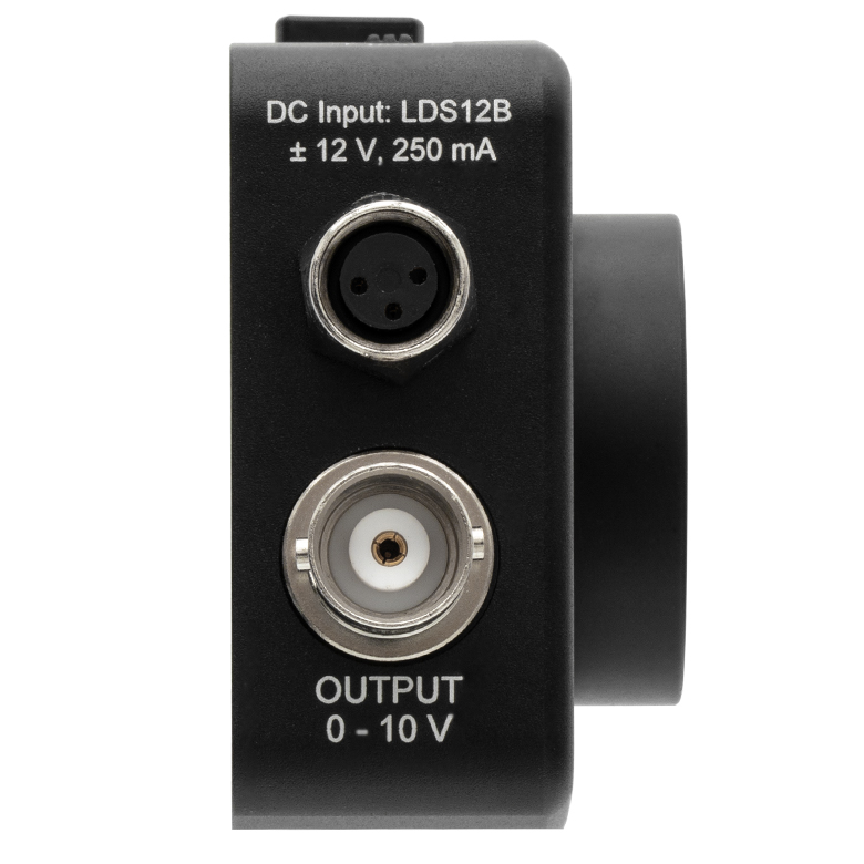
利得切り替えが可能な USB DAQ SiディテクタPDA36AUは、サンプリングレート 1 MS/sの16ビットDAQ機能を備えたシリコンディテクタです。 「ソフトウェア」タブからダウンロードできるPDAソフトウェアを用いて、ディテクタからの信号とユニット上部のSMAコネクタ(ANALOG IN)に入力されるアナログ信号を読み取ることができます。PCとはUSB Type Micro-Bコネクタを介してUSB 2.0で接続できます。この接続により、デバイスへの電源供給とともに、ソフトウェアを用いたDAQからの信号とアナログ入力信号の読み取り、およびそれらの表示が可能になります。もう1つのSMAコネクタ(TRIGGER IN)を介してトリガ信号を入力することができ、そのトリガの設定もソフトウェアで行うことができます。コネクタの位置については「筐体の特長」タブのFigure 3.2をご覧ください。
PDAソフトウェアは仮想2チャンネルオシロスコープとして機能し、ライブモード、記録モード、再生モードの3つのモードで動作します。これらの動作により、ディテクタ信号とアナログ入力信号を時系列で読み取って表示したり、データを保存してそれを再生表示したりすることができます(ライブモードのスクリーンショットはFigure G4.1参照)。またこのソフトウェアでは、トリガーレベルを適切に設定したり、時間軸や電圧軸に沿ってウィンドウをズーム調整して表示範囲や中心位置を適切に設定したりするなど、様々な調整ができます。そのほかにも、時間・電圧に対応する水平・垂直方向のカーソル、残像表示やスムージング表示、調整可能な時間・電圧・トリガ設定、信号の統計処理、データや画面のエクスポートなど、オシロスコープとしての様々な機能を装備しています。 デバイスの利得も、このソフトウェアで0 dB~70 dBの範囲を8段階(10 dB刻み)で設定できます。各利得設定についての詳細は「仕様」タブをご覧ください。ソフトウェアで表示される信号の帯域幅は、ADCサンプリングレートによって制限されていることにご注意ください。PDA制御ソフトウェアの詳細については「ソフトウェア」タブを参照してください。
ディテクタPDA36AUには、カプラSM1TI、固定リングSM1RR、USB 2.0 Type-A - Micro-Bケーブル、スナップオン式プラスチック製ダストキャップ(型番SM1EC2B、交換用は5個入りで別途販売)が付属します。
| Item #a | Housing Featuresb | Wavelength Range | ADC Sampling Rate | ADC Resolution | Gainc | NEP | Typical Performance Graph | Active Area (Click Link for Image) | Operating Temperature Range | Power |
|---|---|---|---|---|---|---|---|---|---|---|
| PDA36AUc |  | 350 - 1100 nm | 1 MS/s | 16 bit | 1.51 kV/A ±2% - 4.75 MV/A ±5% | 4.29 - 75.7 pW/Hz1/2 | 13 mm2 (3.6 mm x 3.6 mm) | 10 to 40 °C | USB Micro-B |

 ズーム
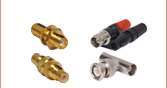
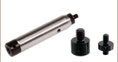
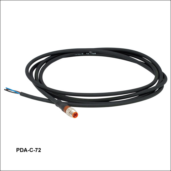
ズーム Figure 304A ケーブルのオスコネクタ
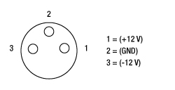
PDA-C-72はPDAシリーズの増幅フォトディテクタ用の電源コードで、ディテクタに付属している電源以外の電源を接続する際にご使用いただけます。コードの片端はリード線が、反対側にはPDAに対応した3ピンコネクタが付いています。このケーブルにより、適切なDC電圧を供給する電源であれば、PDAシリーズの増幅フォトディテクタに使用することができます。ピン情報はFigure 304をご参照ください。

 ズーム
ズーム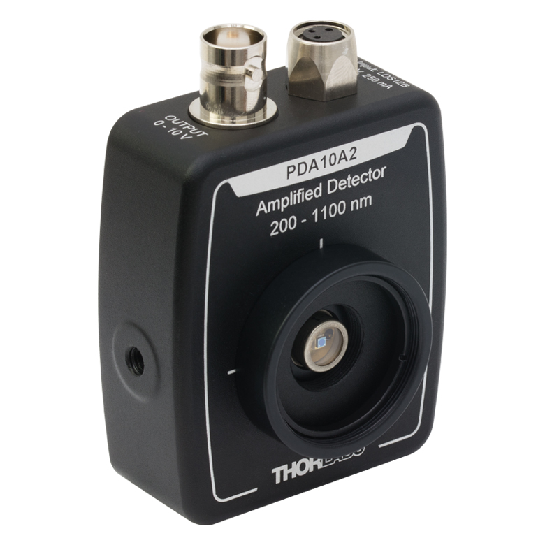
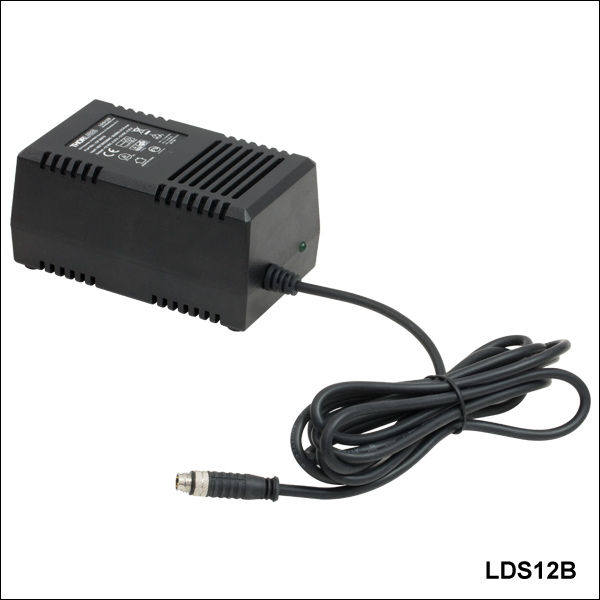
 Figure 506A 電源ケーブル
- PDAシリーズ、PDFシリーズの増幅フォトディテクタ(上記掲載)の交換用電源
- ±12 VDC出力
- 短絡回路を保護しオーバーロードを防ぐ電流リミット機能
- LED表示付きのOn/Offスイッチ
- AC入力電圧はスイッチ切り替え可能(100/120/230 VAC)
- 長さ2 mのケーブルはLUMBERG製オス型コネクタRSMV3付き
この±12 VDC安定化リニア電源LDS12Bは、上記掲載のPDAおよびPDFシリーズの増幅フォトディテクタに付属する電源の交換用製品です。ケーブルに付いているコネクタは3ピンで、グランド用、+12 V用、-12 V用となっています(Figure 506A参照)。日本国内仕様の電源ケーブルが付属します。また、この電源は当社のPDBシリーズの差分ディテクタ(バランスディテクタ)、PMMシリーズの光電子増倍管モジュール、APDシリーズのアバランシェフォトディテクタ、フェムト秒レーザ用オートコリレータFSACにも対応しています。
- FC/PC(ナローキーまたはワイドキー)、FC/APC(ナローキーまたはワイドキー)、SMA、ST®*/PC、SC/PC、 LC/PC、またはØ2.5 mmフェルールレセプタクル付き
- SM1レンズチューブとの組み合わせで遮光可能
- 当社の多くのフォトダイオードパワーセンサに対応
注: APCアダプタの前面には 2つの窪みがあり、スパナレンチSPW909またはSPW801を用いて締め付け可能です。このアダプタをSM1レンズチューブと遮光用途でお使いいただけるように、窪みはディスクを貫通していません。
FC/PCおよびFC/APCアダプタには、ナローキー(2.0 mm)とワイドキー(2.2 mm)の2種類のコネクタをご用意しております。ナローキーとワイドキーの詳細については、光ファイバとは のページをご覧ください。
フェルール用アダプタS120-25は、ロッキングコネクタ機構無しの設計になっています。Ø2.5 mmフェルール付きのファイバーパッチケーブルに対応し、フォトディテクタやパワーセンサを用いた測定を迅速に行うことができます。
| Item # | S120-FC2a | S120-FCa | S120-APC2b | S120-APCb | S120-SMA | S120-ST | S120-SC | S120-LC | S120-25a |
|---|---|---|---|---|---|---|---|---|---|
| Adapter Image (Click the Image to Enlarge) | 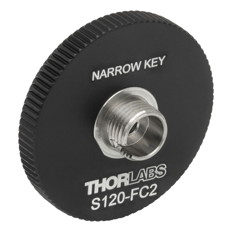 | 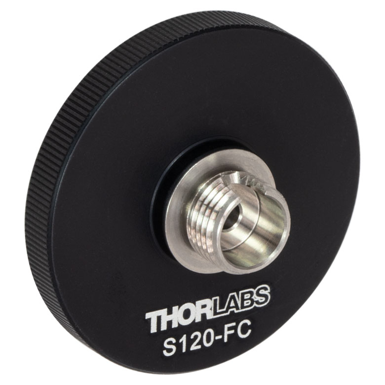 | 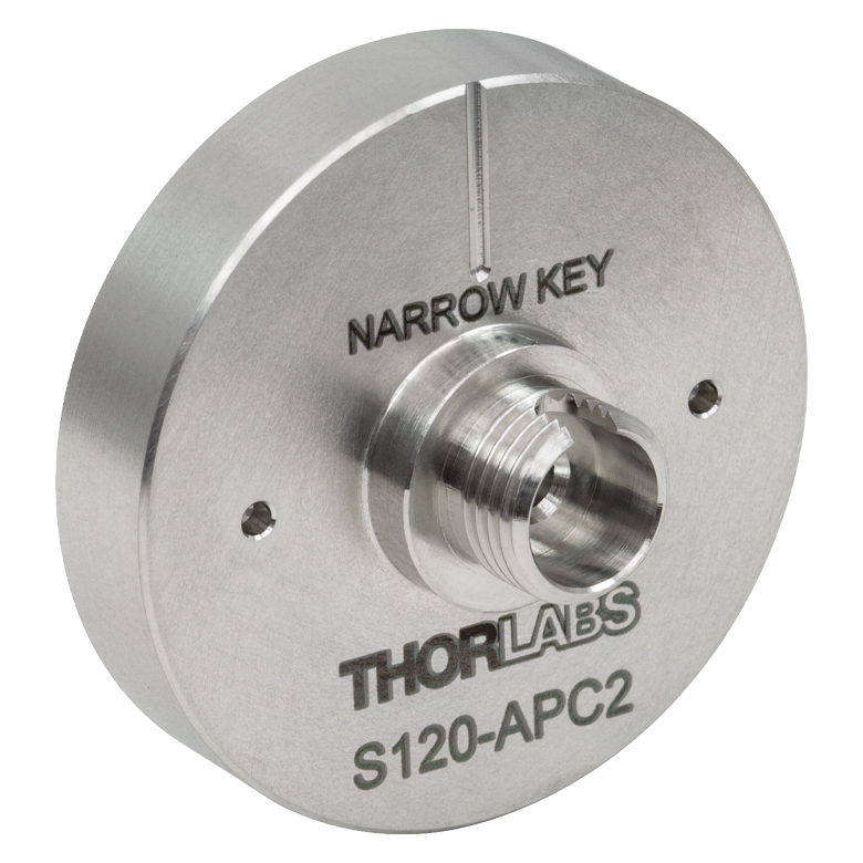 | 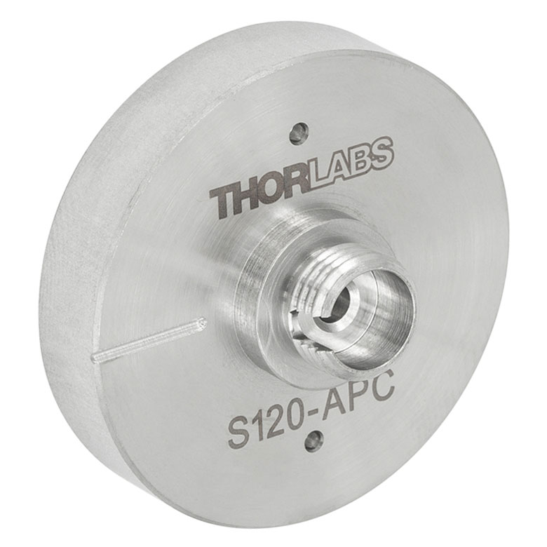 | 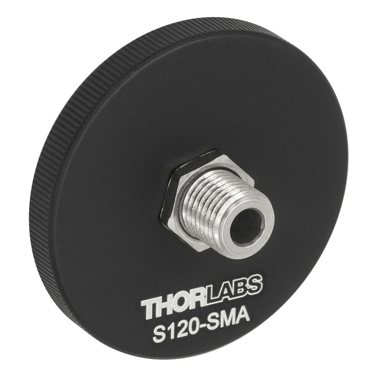 | 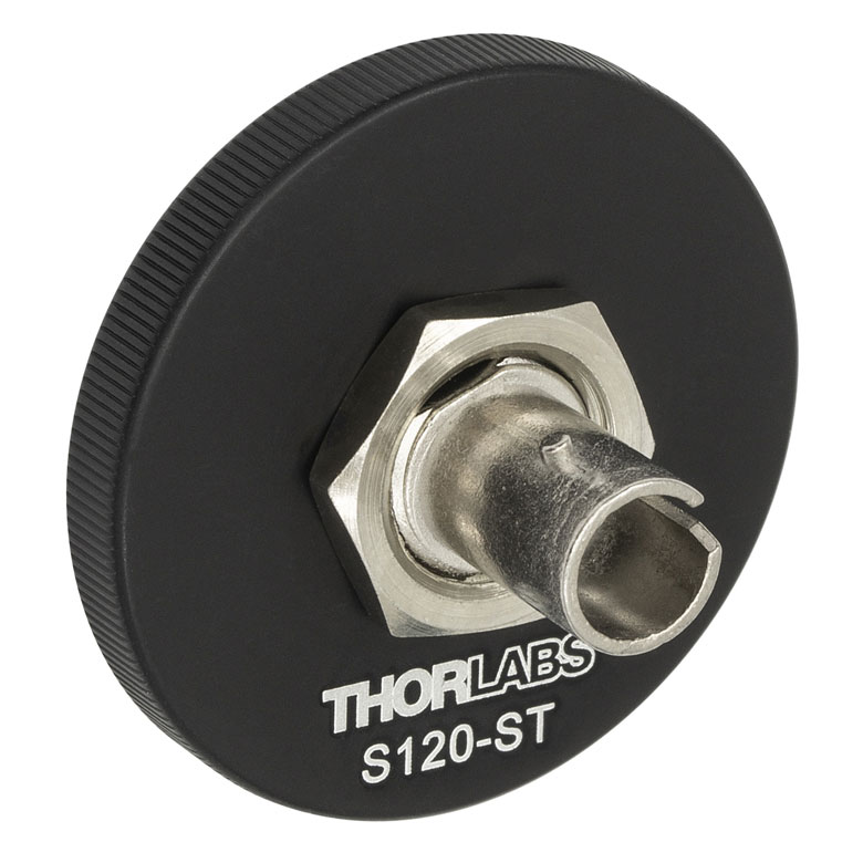 | 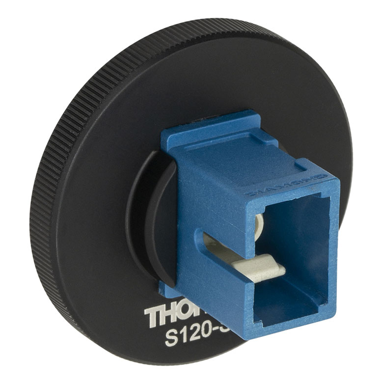 | 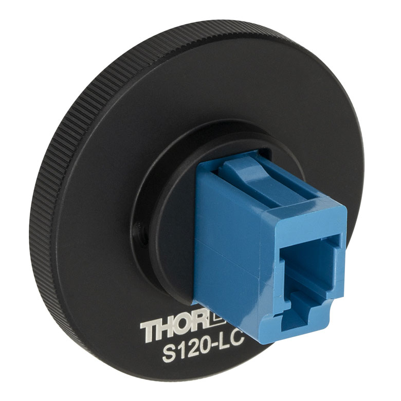 |  |
| Fiber Connector Type | FC/PC, 2.0 mm Narrow Key | FC/PC, 2.2 mm Wide Key | FC/APC, 2.0 mm Narrow Key | FC/APC 2.2 mm Wide Key | SMA | ST/PC | SC/PCc | LC/PC | Ø2.5 mm Ferrule |
| Threading | Internal SM1 (1.035"-40) | ||||||||
*ST®はLucent Technologies社の登録商標です。
- FC/PC(ナローキーまたはワイドキー)、FC/APC(ナローキーまたはワイドキー)、SMA、ST®*/PC、SC/PC、 LC/PCレセプタクル付き
- FC/PC(ワイドキー)とSMAレセプタクルは真空対応の製品もご用意
- SM1レンズチューブとの組み合わせで遮光可能
- 当社の多くの30 mmケージプレートならびにフォトディテクタに対応
注: 各ディスクには4つの窪み(前面と背面に2つずつ)があり、どちらの面からもスパナレンチSPW909またはSPW801で締め付け可能です。アダプタをSM1レンズチューブと遮光用途で使用できるよう、窪みはディスクを貫通していません。アダプタの位置確定後は、固定リングSM1RRで固定してください。
FC/PCおよびFC/APCアダプタには、ナローキー(2.0 mm)とワイドキー(2.2 mm)の2種類のコネクタをご用意しております。ナローキーとワイドキーの詳細については、光ファイバとはのページをご覧ください。
| Item # | SM1FC2 | SM1FC | SM1FCV | SM1FCA2a | SM1FCAa | SM1SMA | SM1SMAV | SM1ST | SM1SC1b | SM1LCb |
|---|---|---|---|---|---|---|---|---|---|---|
| Adapter Image (Click the Image to Enlarge) | 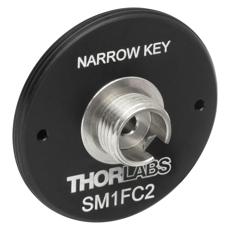 | 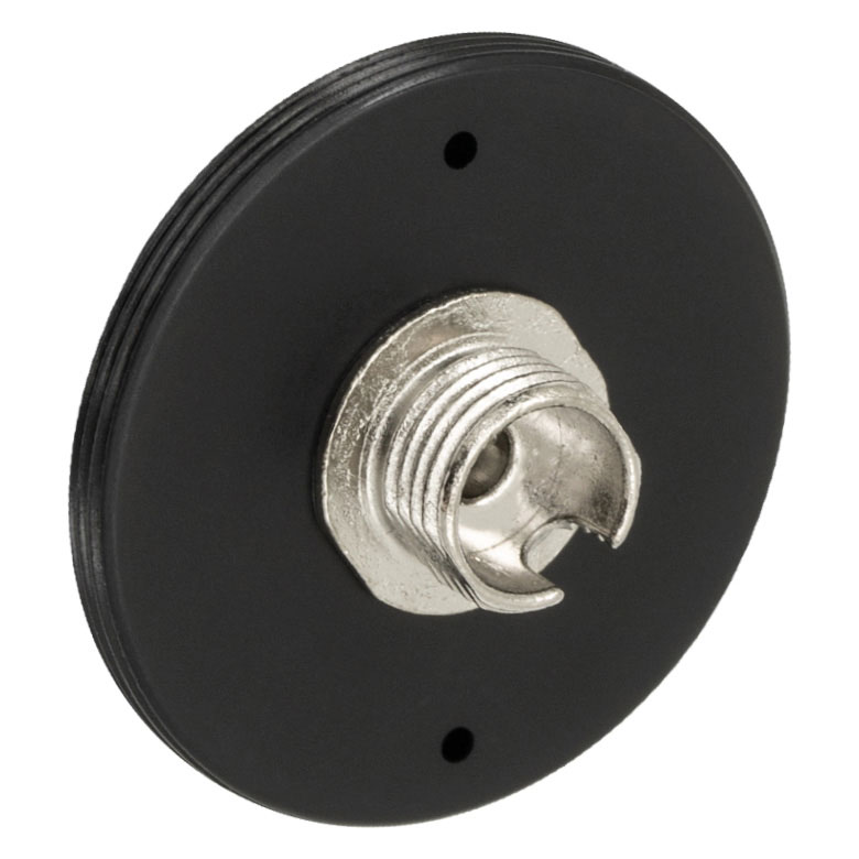 | 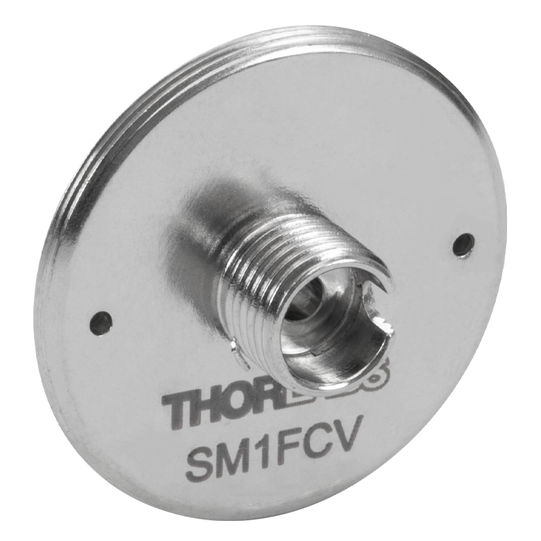 |  |  | 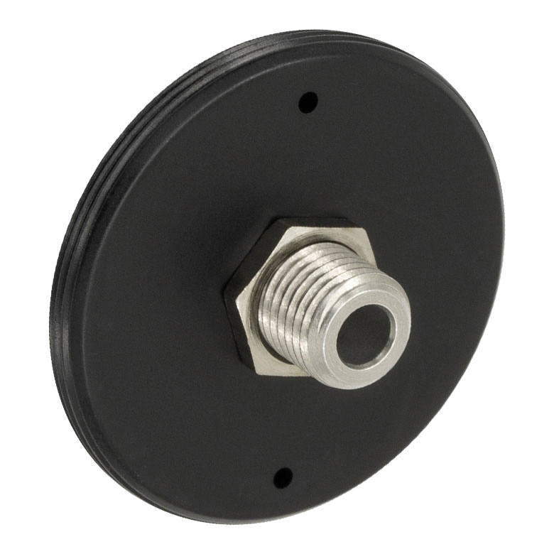 | 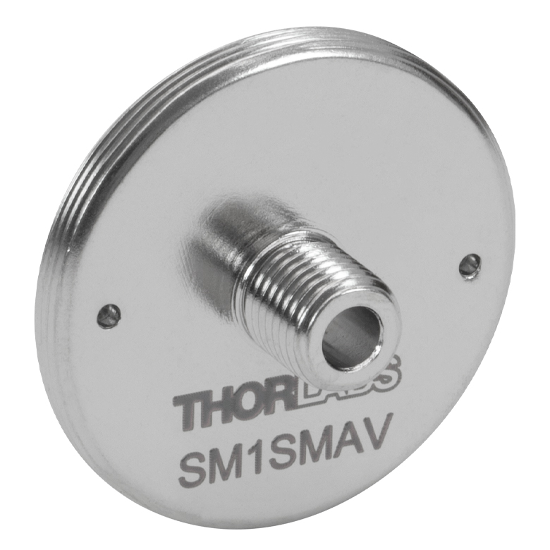 | 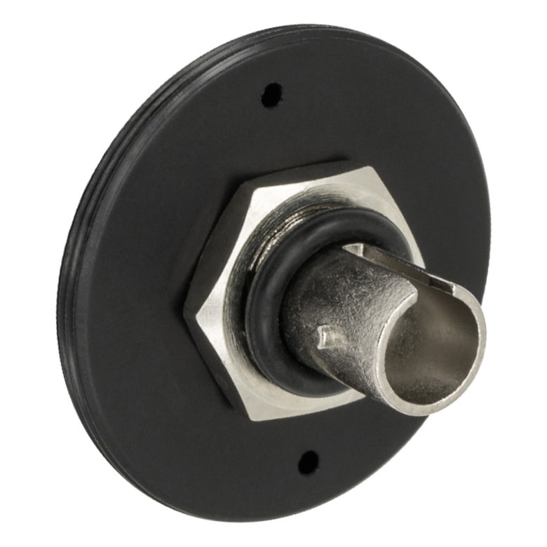 | 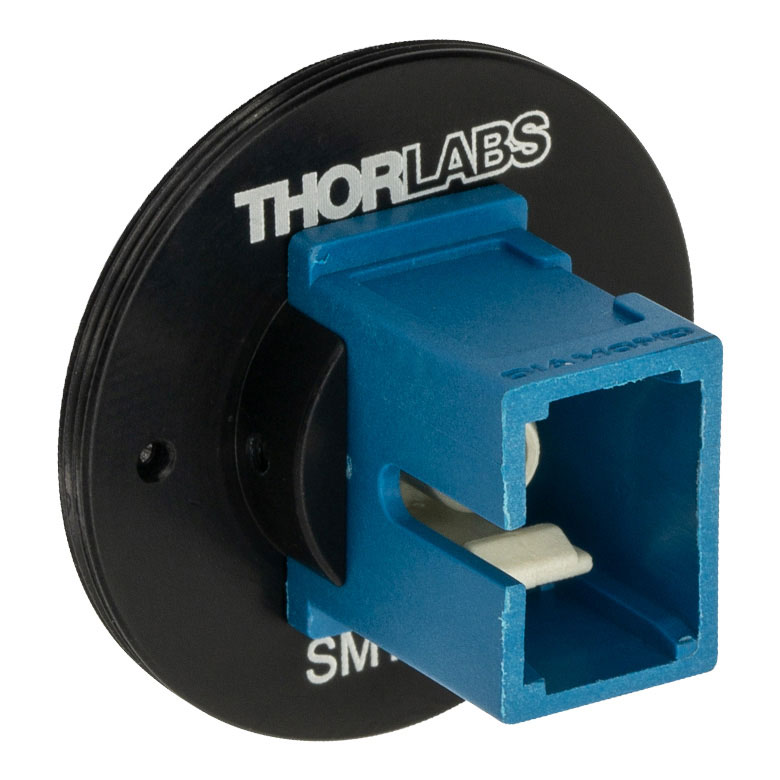 |  |
| Connector Type | FC/PC, 2.0 mm Narrow Key | FC/PC, 2.2 mm Wide Key | FC/PC, 2.2 mm Wide Key | FC/APC, 2.0 mm Narrow Key | FC/APC, 2.2 mm Wide Key | SMA | SMA | ST/PC | SC/PCc | LC/PC |
| Vacuum Compatibility | - | >10-10 Torr | - | >10-10 Torr | - | |||||
| Threading | External SM1 (1.035"-40) | |||||||||
*ST®はLucent Technologies社の登録商標です。