 Products Home
蛍光イメージングフィルタ
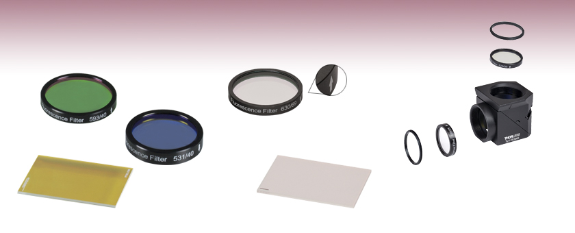
- Excitation, Emission, and Dichroic Filters for Imaging Applications
- Matched Filter Sets Designed for Wavelength Ranges of Common Fluorophores
MD568
Dichroic Mirror
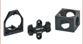
MDF-TOM
Filter Set
MF630-69
Emission Filter
Arrow Indicates
Direction of Light
Propagation
Etched Corner Indicates Dichroic-Coated Side
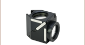
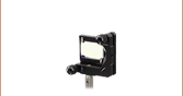
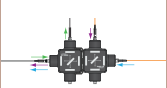
Exploded View of a Filter Set Installed Into a Filter Cube
Dichroic
Mirror
Inside Cube
Excitation
Filter
Emission
Filter
Image Plane
Retaining
Ring
Retaining
Ring


Please Wait
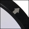
励起フィルタおよび吸収フィルタは、推奨する光の伝搬方向がマウント上に矢印で示されています。
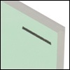
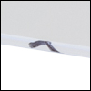
ダイクロイックフィルタはダイクロイックコーティングが施されている側に印が付いています。 コーティング面から光を入射することをお勧めします。
特長
- 蛍光イメージング用の励起フィルタ、吸収フィルタ、ダイクロイックフィルタ
- 設計波長で>90%の透過率
- 透過帯域外でシャープなカットオフ (T< 0.001%)
- 多くの一般的な蛍光物質に対応するフィルターセット
- BFP
- CFP
- WGFP
- GFP
- FITC
-Alexa Fluor®∗ 488- YFP
- tdTomato
- TRITC
- Texas Red®*
- mCherry
- Cy®†3.5- Cy5
- Cy5.5
- Cy7
- LI-COR IRDye®‡ 800CW - 励起フィルタや吸収フィルタは黒アルマイト処理を施した筐体にマウント
- ダイクロイックフィルタはマウント無し
- フィルターセットは単品でお買い求めいただく場合よりも割引価格でご提供
こちらでご紹介している励起フィルタ、吸収フィルタ、ダイクロイックフィルタは、蛍光イメージング用に特別に設計されています。 業界標準のサイズなので、主要メーカのフィルターキューブにお使いいただけます。 フィルタおよびフィルターセットは一般的な蛍光色素分子(BFP、CFP、WGFP、GFP、FITC、Alexa Fluor 488、YFP、tdTomato、TRITC、Texas Red、mCherry、Cy3.5、Cy5、Cy5.5、Cy7、LI-COR IRDye 800CW)に対応するラインナップです。フィルタの多くは単体でご提供していますが、励起フィルタ、吸収フィルタ、およびダイクロイックフィルタの3枚セットでのみご提供しているフィルタもございます。詳細は「仕様」タブをご覧ください。これらのフィルタは顕微鏡用フィルターキューブに取付け済でもご用意しています。
フィルタ設計
当社のフィルタは高性能の光学仕様で、耐久性の高い設計となっています。 高精度溶融石英基板上に誘電体多層膜を蒸着して製造されています。 この基板は高品質の画像を維持するために研磨されています。 このような光学素子では、電子ビーム蒸着法で作られたものよりフィルタ層は高密度になります。高密度フィルタは、水分吸収が少ないので、フィルタの耐久性、安定性そして性能が格段に良くなります。 各フィルタ層は形成中に厚さをモニタリングしているので、設計仕様で定められた厚さからのズレが最小限に抑えられ、結果としてフィルタの全般的な性能が維持されます。
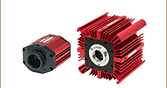
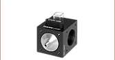
励起フィルタと吸収フィルタは、黒色アルマイト処理されたØ25 mmリングに取り付けられているため取扱いが容易で、またそれにより散乱光が制限されるため透過阻止性能(OD値)も向上します。これらのフィルタは、当社の様々なフィルターマウントやフィルターホイールに取り付けることができます。アルミニウム製リングにはネジが切られていないため、Ø25 mmフィルタを当社の内ネジ付きSM1レンズチューブに取り付ける際は、固定リングが必要になります。これらのフィルタを当社製、Olympus製、またはNikon製の蛍光顕微鏡でお使いになる場合には、ドロップイン式顕微鏡用フィルターキューブをご利用いただけます。また、マウント無しの25 mm x 36 mmダイクロイックフィルタは、キネマティックマウントKM2536に取付けることができます。このマウントは厚さ1 mmの長方形光学素子を最小の取付け負荷で固定できるように設計されています。
∗Alexa Fluor とTexas RedはMolecular Probes社の登録商標です。
†CyはGlobal Life Sciences Solutions Germany社の登録商標です。
‡IRDyeはLI-COR Biotech社の登録商標です。
| Item # | Size | Clear Aperture | Angle of Incidence | Thickness | Surface Quality | Substrate |
|---|---|---|---|---|---|---|
| Excitation Filters | ||||||
| MDF-GFP2, MDF-TOM, MDF-MCHC, & MDF-MCHA Kits | Ø25 +0.0/-0.1 mm | >Ø21 mm | 0° ± 5 | 5.0 ± 0.1 mm | 60-40 Scratch-Dig | Fused Silica |
| MDF-CY5, MDF-CY55, MDF-CY7, & MDF-NIR Kits | Ø25.0 ± 0.1 mm | ≥Ø22 mm | Alkaline Earth Boro-Aluminosilicate | |||
| All Other Excitation Filters | Ø25 ± 0.1 mm | >Ø21 mm | Fused Silica | |||
| Emission Filters | ||||||
| MDF-GFP2, MDF-TOM, MDF-MCHC, & MDF-MCHA Kits | Ø25 +0.0/-0.1 mm | >Ø22 mm | 0° ± 5° | 3.5 ± 0.1 mm | 60-40 Scratch-Dig | Fused Silica |
| MDF-CY5, MDF-CY55, MDF-CY7, & MDF-NIR Kits | Ø25.0 ± 0.1 mm | ≥Ø22 mm | ||||
| All Other Excitation Filters | Ø25 ± 0.1 mm | >Ø21 mm | ||||
| Dichroic Filters | ||||||
| MDF-GFP2, MDF-TOM, MDF-MCHC, & MDF-MCHA Kits | 25.2 mm x 35.6 mm | 80% of Area | 45° ± 1.5° | 1.05 ± 0.05 mm | 60-40 Scratch-Dig | Fused Silica |
| MDF-CY5, MDF-CY55, MDF-CY7, & MDF-NIR Kits | 25.0 mm x 35.8 mm | ≥22 mm x 33 mm (Elliptical) | 1.0 ± 0.1 mm | |||
| All Other Excitation Filters | 25.0 mm x 36.0 mm | >(22.5 mm x 32.4 mm) | ||||
| Item # | Kit Item # | Fluorophore | Filter Type | Center Wavelength | FWHM | Reflection Band | Transmission Band | AR Coatinga | Transmission Datab |
|---|---|---|---|---|---|---|---|---|---|
| MF390-18 | MDF-BFP | BFP | Excitation | 390 nm | 18 nm | - | - | - | |
| MF460-60 | Emission | 460 nm | 60 nm | - | - | - | |||
| MD416 | Dichroic | - | - | Ravg > 90% 360 - 407 nm | Tabs > 90% 425 - 575 nm | Rabs < 2% from 400 to 800 nm | |||
| MF434-17 | MDF-CFP | CFP | Excitation | 434 nm | 17 nm | - | - | - | |
| MF479-40 | Emission | 479 nm | 40 nm | - | - | - | |||
| MD453 | Dichroic | - | - | Ravg > 90% 423 - 445 nm | Tabs > 90% 460 - 610 nm | Rabs < 2% from 400 to 800 nm | |||
| MF445-45 | MDF-WGFP | WGFP | Excitation | 445 nm | 45 nm | - | - | - | |
| MF510-42 | Emission | 510 nm | 42 nm | - | - | - | |||
| MD480 | Dichroic | - | - | Ravg > 90% 415 - 470 nm | Tabs > 90% 490 - 720 nm | Rabs < 2% from 400 - 800 nm | |||
| MF469-35 | MDF-GFP | GFP | Excitation | 469 nm | 35 nm | - | - | - | |
| MF525-39 | Emission | 525 nm | 39 nm | - | - | - | |||
| MD498 | Dichroic | - | - | Ravg > 90% 452 - 490 nm | Tabs > 90% 505 - 800 nm | Rabs < 2% from 400 to 800 nm | |||
| MF475-35 | MDF-FITC | FITC | Excitation | 475 nm | 35 nm | - | - | - | |
| MF530-43 | Emission | 530 nm | 43 nm | - | - | - | |||
| MD499 | Dichroic | - | - | Ravg > 90% 470 - 490 nm | Tabs > 90% 508 - 675 nm | Rabs < 2% from 400 to 800 nm | |||
| - | MDF-GFP2 | GFP Alexa Fluor® 488 | Excitation | 482 nm | 18 nm | - | - | - | |
| - | Emission | 520 nm | 28 nm | - | - | - | |||
| - | Dichroic | - | - | Ravg > 93% 350 - 488 nm | Tavg > 93% 502 - 950 nm | - | |||
| MF497-16 | MDF-YFP | YFP | Excitation | 497 nm | 16 nm | - | - | - | |
| MF535-22 | Emission | 535 nm | 22 nm | - | - | - | |||
| MD515 | Dichroic | - | - | Ravg > 90% 490 - 510 nm | Tabs > 90% 525 - 700 nm | - | |||
| - | MDF-TOM | tdTomato | Excitation | 531 nm | 40 nm | - | - | - | |
| - | Emission | 593 nm | 40 nm | - | - | - | |||
| - | Dichroic | - | - | Ravg > 98% 350 - 555 nm | Tavg > 93% 569 - 950 nm | - | |||
| MF542-20 | MDF-TRITC | TRITC | Excitation | 542 nm | 20 nm | - | - | - | |
| MF620-52c | Emission | 620 nm | 52 nm | - | - | - | |||
| MD568 | Dichroic | - | - | Ravg > 90% 525 - 556 nm | Tabs > 90% 580 - 650 nm | Rabs < 2% from 400 to 800 nm | |||
| MF559-34 | MDF-TXRED | Texas Red® | Excitation | 559 nm | 34 nm | - | - | - | |
| MF630-69 | Emission | 630 nm | 69 nm | - | - | - | |||
| MD588d | Dichroic | - | - | Ravg > 90% 533 - 580 nm | Tabs > 90% 595 - 800 nm | Rabs < 2% from 400 to 800 nm | |||
| - | MDF-MCHC | mCherry | Excitation | 562 nm | 40 nm | - | - | - | |
| - | Emission | 641 nm | 75 nm | - | - | - | |||
| - | Dichroic | - | - | Ravg > 98% 350 - 585 nm | Tavg > 93% 601 - 950 nm | - | |||
| MF565-24 | MDF-CY3.5 | Cy®3.5 | Excitation | 565 nm | 24 nm | - | - | - | |
| MF620-52c | Emission | 620 nm | 52 nm | - | - | - | |||
| MD588d | Dichroic | - | - | Ravg > 90% 533 - 580 nm | Tabs > 90% 595 - 800 nm | Rabs < 2% from 400 to 800 nm | |||
| - | MDF-MCHA | mCherry | Excitation | 578 nm | 21 nm | - | - | - | |
| - | Emission | 641 nm | 75 nm | - | - | - | |||
| - | Dichroic | - | - | Ravg > 98% 350 - 588 nm | Tavg > 93% 603 - 950 nm | - | |||
| - | MDF-CY5 | Cy5 | Excitation | 619 nm | 60 nm | - | - | - | |
| - | Emission | 700 nm | 71 nm | - | - | - | |||
| - | Dichroic | - | - | Ravg ≥ 98% 500 - 648 nm | Tavg ≥ 95% 666 - 890 nm | - | |||
| - | MDF-CY55 | Cy5.5 | Excitation | 650 nm | 44 nm | - | - | - | |
| - | Emission | 720 nm | 59.5 nm | - | - | - | |||
| - | Dichroic | - | - | Ravg > 98% 520 - 674 nm | Tavg ≥ 95% 692 - 1000 nm | - | |||
| - | MDF-CY7 | Cy7 | Excitation | 709 nm | 75.5 nm | - | - | - | |
| - | Emission | 813 nm | 96 nm | - | - | - | |||
| - | Dichroic | - | - | Ravg > 98% 570 - 746 nm | Tavg ≥ 95% 766 - 1100 nm | - | |||
| - | MDF-NIR | LI-COR IRDye® 800CW | Excitation | 741 nm | 41 nm | - | - | - | |
| - | Emission | N/Ae | - | - | - | - | |||
| - | Dichroic | - | - | Ravg > 98% 580 - 760 nm | Tavg ≥ 95% 780 - 1100 nm | - |
- 背面に入射角45°のARコーティングが施されたダイクロイックフィルタ
-
 をクリックすると、プロット図やダウンロード可能なデータをご覧いただけます。
 - TRITCおよびCY3.5用
- CY3.5およびTXRED用
- この吸収フィルタのカットオン波長は780 nm、790~1000 nmでの平均透過率は≥94%です。
 Click to Enlarge
蛍光顕微鏡用フィルタ
蛍光色素
蛍光色素は蛍光を生み出す分子または分子の一部です。分子が基底状態から励起状態まで移るのに必要な周波数の光を受けることで、励起が生じます。しかし、分子はいったん励起状態になると不安定になります。短い時間(通常10-15~10-9秒)の後、光子(フォトン)はリリースされ、分子は低い励起状態に戻ります。振動や音、熱エネルギのような多様なメカニズムによるエネルギの損失を通じて、放射光は吸収光より長い波長(低いエネルギ)になります。
単体の蛍光色素分子はフォトブリーチングによる破壊(光励起のケミカルダメージや共有結合修飾による不可逆破壊)がなければ、連続して励起することが可能です。フォトブリーチングの前に特定の蛍光色素が受ける励起および発光サイクルの平均的な数は、蛍光色素の分子構造と局所的環境により変わります。数個の光子を放出した直後にフォトブリーチングする蛍光色素分子もあれば、ずっと強固でブリーチする前に何千あるいは何億ものサイクルを経験する蛍光色素分子もあります。
蛍光顕微鏡用フィルタ
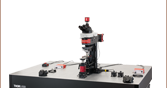
右の実験セットアップは、励起光と蛍光の両方が顕微鏡対物レンズを通過する落射蛍光顕微鏡で使われている一般的なフィルタを示しています。用途に合わせて適切なフィルタとミラーを慎重に選ぶことによって、信号対雑音比は最大化されます。右図のように、不要な放射を最小に抑えながら蛍光信号を最大にするために3種類のフィルタが使われています。各光学素子の解説は、下に掲載されています。
励起フィルタ
励起フィルタは、蛍光色素の励起のピーク波長近傍の狭い波長範囲しか透過しません。例えば右のグラフのように、YFP励起フィルタ(MF497-16)の90%を超える透過率に対応するバンドパス領域は489~505 nmです。この範囲外の入射は一部(透過領域に近い領域で)または全部(バンドパス領域から離れた領域で)がフィルタによって阻止されます。
ダイクロイックミラー
ダイクロイックミラーは、特定の波長(カットオフ波長)よりも短い波長の光を反射しますが、それ以外の波長はすべてそのまま通過するよう設計されています。顕微鏡では、ダイクロイックミラーによって適切な波長が試料および像面に向けられます。 各ミラーに対応したカットオフ波長の値は透過の50%に対応する波長を示しています。例えば、右図に示されているように、YFPダイクロイックミラー(MD515)のカットオフ波長は約515 nmとなります。 「仕様」タブには各ダイクロイックミラーの反射率および透過率に関する情報がごらんいただけます。
ダイクロイックミラー1枚を実験セットアップで入射に対して45°に配置することにより、励起光(上図内に青色で表示)はダイクロイックミラーの表面から反射され、試料と顕微鏡対物レンズへと向かいます。一方、試料から発する蛍光(上図内に赤色で表示)はミラーを透過して検出システムへと向かいます。
ダイクロイックミラーは蛍光顕微鏡で重要な役割を果たしますが、不要な光を遮断することとなると完璧とは言えません。一般に、ダイクロイックミラーにより、カットオフ波長より短い波長の光の約90%は反射され、これより長い波長の光の約90%は透過されます。そのため、試料によって放射される(励起光より)長波長の蛍光と一緒に、励起光の一部もダイクロイックミラーを透過してしまいます。 この不要な光が検出システムに届くのを防ぐために、ダイクロイックフィルタのほかに吸収フィルタが使われます。
吸収フィルタ
吸収フィルタは不要な励起光を遮断しながら試料からの蛍光をディテクタに届ける役割を果たします。励起フィルタ同様に、このフィルタは蛍光色素の発光のピーク波長近傍の狭い帯域幅しか透過しません。例えば、右のグラフのように、YFP吸収フィルタ(MF535-22)の90%を超える透過率に対応するバンドパス領域は524~546 nmです。この範囲外の入射は一部(透過領域に近い領域で)または全部(バンドパス領域から離れた領域で)がフィルタによって阻止されます。
| Posted Comments: | |
Sashank Sriram
(posted 2025-03-30 21:06:51.65) Hi, I am curious if the dichroic mirrors presented here are polarisation sensitive. Since the mirrors are typically aligned at 45 degrees with the incoming beam of light, the electric fields can be either in-plane or out of the plane of the mirror. I would expect the two polarisations to interact differently with the components. Is there a significant difference in the performance of your dichroic mirrors versus the polarisation of light? blarowe
(posted 2025-03-31 03:37:27.0) Thank you for contacting Thorlabs. Generally, we would expect some polarization dependence from these filters. I've reached out to you directly with more details. Yuan Gong
(posted 2023-12-28 12:08:46.28) Hi,
May I ask about the absorption of the filters, like MF525-39? I would like to buy a pair of this product, and I care about its reflection in the stop band. Can I roughly calculate the reflection at a specific wavelength by R=1-T?
Many thanks! Have a nice one!
Yuan jpolaris
(posted 2024-01-16 04:30:35.0) Thank you for contacting Thorlabs. In general, R = 1-T is not a reliable estimate for reflectance in the stop band because it ignores the effects of absorption and interference which could be part of the blocking mechanism. I have reached out to directly with reflectance data. Priyanka Jangra
(posted 2023-09-13 22:19:46.323) We want to know about the product FMF003 availability and price jdelia
(posted 2023-09-13 01:33:48.0) Thank you for reaching out. FMF003 was obsoleted and replaced by MF535-22. You can find pricing and availability information for this product directly on the product family page. Kevin Cappa
(posted 2020-03-04 17:50:33.503) If I had the option to get a 2"/50mm filter set for FITC fluorescent imaging I would... nbayconich
(posted 2020-03-05 01:03:35.0) Thank you for your feedback, I will log your request in our internal engineering forum for future reference. We can provide custom sized filters upon request, I will reach out to you directly to discuss our custom capabilities. tcohen
(posted 2012-09-13 11:44:00.0) Response from Tim at Thorlabs: Thank you for your interest in our custom capabilities. We should be able to provide this as a special and I have contacted you to go over your requirements. densta
(posted 2012-09-13 12:33:11.0) Dear Madam/Sir
I want to perform some preliminary fluorescence tests for a project of ours.
I am interested in buying one of the following emission filters
MF525-39: GFP
MF530-43: FITC
I noticed from your records that the outer diameter of the filter is 25 mm.
In our system we need a filter with outer diameter 17 mm. The filter could be bare glass without an outer support ring. Is it possible to have one of the above mentioned filters in this form? What would be the cost?
Best regards,
Dimosthenis Stamopoulos bdada
(posted 2012-02-24 17:13:00.0) Response from Buki at Thorlabs to
Thank you for your interest in our imaging dichroic filters.
Testing has shown no signs of degradation when exposed to at least 6 W of power from an unfiltered xenon arc lamp over a 25 mm diameter (corresponding to 1.2 W/cm2) for over 500 hours.
Please contact TechSupport@thorlabs.com if you have any questions. user
(posted 2012-02-10 13:05:04.0) Can you please provide laser damage threshold ratings for the dichroic filters? jjurado
(posted 2011-03-22 16:05:00.0) Response from Javier at Thorlabs to flickingerd: Thank you for your feedback. Our filters follow that same convention as that of Semrock's. The arrow points to the recommended direction of light propagation. The reason for this is although the filter will function with either side facing the source, it is recommended to place the coated side toward the source. This will minimize any thermal effects or possible thermal damage that blocking intense out-of-band radiation might cause due to absorption by the substrate or colored glass filter layers. lmorgus
(posted 2011-03-21 18:23:00.0) A response from Laurie at Thorlabs to flickingerd: As a follow-up to the response you received earlier today from Javier in our technical support group, I wanted to also reach out to you to thank you for your feedback. We have updated our web presentation to provide information about what the arrow on these optic mounts indicates. As a further step, we have made a list of other web pages on our site that need some attention for similar reasons. In the coming days, we will be updating those pages to clarify our engravings so that our customers can efficiently find the information they need to use our products effectively. Again, thank you for taking the time to drop us a note with a suggestion for improvement. flickingerd
(posted 2011-03-21 14:29:07.0) I couldnt find info on proper filter orientation. There are arrows on the filters, but Ive seen different conventions on what these mean (Chroma says point arrow towards specimen for emission filters, yet Semrock convention is always point arrow in direction of light propagation, I think). How about your filters? This should be in "Tutorial" section, Id think. Please contact me with proper orientation rules. (Although Im still not sure exactly why this matters...I guess I can think of some minor reasons...) apalmentieri
(posted 2010-02-18 09:42:22.0) A response from Adam at Thorlabs to pludowise: I believe we should be able to offer this item as a custom option. I would like to contact you directly to get more information about your application, the quantity necessary, and the exact size of the optic. pludowise
(posted 2010-02-18 00:01:38.0) I am interested in finding a dichroic filter similar to MDF-TXRED, but shifted to loger wavelengths. Specifically, I need a dichroic for a Cy5 dye, which needs to transmit at 640 nm, and reflect at 690 nm. I also need this in a 1 mm thickness mounted at 45 deg AOI. Thank you. |

 ズーム
ズーム| Item # | Transmission Dataa | Design Fluorophore | Center Wavelength | FWHM |
|---|---|---|---|---|
| MF390-18 | Blue Fluorescent Protein (BFP) | 390 nm | 18 nm | |
| MF434-17 | Cyan Fluorescent Protein (CFP) | 434 nm | 17 nm | |
| MF445-45 | Wild Type GFP (WGFP) | 445 nm | 45 nm | |
| MF469-35 | Green Fluorescent Protein (GFP) | 469 nm | 35 nm | |
| MF475-35 | Fluorescein isothiocyanate (FITC) | 475 nm | 35 nm | |
| MF497-16 | Yellow Fluorescent Protein (YFP) | 497 nm | 16 nm | |
| MF542-20 | Tetramethylrhodamine Isothiocyanate (TRITC) | 542 nm | 20 nm | |
| MF559-34 | Texas Red (TXRED) | 559 nm | 34 nm | |
| MF565-24 | Cyanine (CY3.5) | 565 nm | 24 nm |
 をクリックすると、プロット図やダウンロード可能なデータをご覧いただけます。
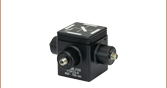
これらの励起蛍光イメージングフィルタは、顕微鏡およびイメージング用途専用に設計されています。Ø25 mmのフィルタは、厚さ 5 mmの黒色アルマイト加工の筐体に取り付けられています。この筐体には推奨する光の伝搬方向を示す矢印が刻印されています。
これらのフィルタは所定の励起波長で優れた透過率(>90%) を、範囲外の波長で鋭いカットオフ特性と低い透過率(<0.001%)を示します。製品ごとの透過率データの詳細に関しては、上のアイコン![]() をクリックしてください。
をクリックしてください。

 ズーム
ズーム| Item # | Transmission Dataa | Design Fluorophore | Center Wavelength | FWHM |
|---|---|---|---|---|
| MF460-60 | Blue Fluorescent Protein (BFP) | 460 nm | 60 nm | |
| MF479-40 | Cyan Fluorescent Protein (CFP) | 479 nm | 40 nm | |
| MF510-42 | Wild Type GFP (WGFP) | 510 nm | 42 nm | |
| MF525-39 | Green Fluorescent Protein (GFP) | 525 nm | 39 nm | |
| MF530-43 | Fluorescein isothiocyanate (FITC) | 530 nm | 43 nm | |
| MF535-22 | Yellow Fluorescent Protein (YFP) | 535 nm | 22 nm | |
| MF620-52 | Tetramethylrhodamine Isothiocyanate/ Cyanine (TRITC/CY3.5) | 620 nm | 52 nm | |
| MF630-69 | Texas Red (TXRED) | 630 nm | 69 nm |
 をクリックすると、プロット図やダウンロード可能なデータをご覧いただけます。
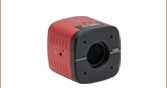
これらの吸収蛍光イメージングフィルタは、顕微鏡およびイメージング用途専用に設計されていて、高速フィルタと使用することによって独自の顕微鏡セットアップを構築することができます。Ø25 mmのフィルタは、厚さ 3.5 mmの黒色アルマイト加工の筐体に取り付けられています。この筐体には推奨する光の伝搬方向を示す矢印が刻印されています。
これらのフィルタは所定の励起波長で優れた透過率 (>90%)を、範囲外の波長で鋭いカットオフ特性と低い透過率(<0.001%)を示します。製品ごとの透過率データの詳細に関しては、上のアイコン![]() をクリックしてください。
をクリックしてください。

 ズーム
ズーム| Item # | Transmission Dataa | Design Fluorophore | Reflection Bandb | Transmission Bandc |
|---|---|---|---|---|
| MD416 | Blue Fluorescent Protein (BFP) | 360 - 407 nm | 425 - 575 nm | |
| MD453 | Cyan Fluorescent Protein (CFP) | 423 - 445 nm | 460 - 610 nm | |
| MD480 | Wild Type GFP (WGFP) | 415 - 470 nm | 490 - 720 nm | |
| MD498 | Green Fluorescent Protein (GFP) | 452 - 490 nm | 505 - 800 nm | |
| MD499 | Fluorescein isothiocyanate (FITC) | 470 - 490 nm | 508 - 675 nm | |
| MD515 | Yellow Fluorescent Protein (YFP) | 490 - 510 nm | 525 - 700 nm | |
| MD568 | Tetramethylrhodamine Isothiocyanate (TRITC) | 525 - 556 nm | 580 - 650 nm | |
| MD588 | Cyanine/Texas Red (CY3.5/TXRED) | 533 - 580 nm | 595 - 800 nm |
 をクリックすると、プロット図やダウンロード可能なデータをご覧いただけます。
- この範囲内での平均反射率は90%以上
- この範囲内での絶対透過率は90%以上
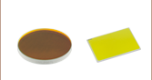
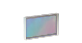
当社のダイクロイックフィルタは波長の異なる光を分離するように設計されています。フィルタに光を45°の角度で入射すると、励起光とそれに伴う後方反射光が反射され、波長の長い蛍光信号は透過します。これらのフィルタにはマウントが付いていませんが、光を入射するフィルタのコーティング面には印が付いています。各フィルタは25.0 mm x 36.0 mmです。円形のマウント付きダイクロイックフィルタが用途に適している場合には、当社の円形ダイクロイックフィルタのご使用をお勧めします。製品ごとの透過データに関しては、上のアイコン![]() をクリックしてください。
をクリックしてください。

 ズーム
ズーム| Item # | Transmission Dataa | Design Fluorophore | Excitation Band | Emission Band | Dichroic (Reflection / Transmission Band) |
|---|---|---|---|---|---|
| MDF-BFP | Blue Fluorescent Protein (BFP) | 390 ± 9 nm | 460 ± 30 nm | 360 - 407 nm / 425 - 475 nm | |
| MDF-CFP | Cyan Fluorescent Protein (CFP) | 434 ± 8.5 nm | 479 ± 20 nm | 423 - 445 nm / 460 - 610 nm | |
| MDF-WGFP | Wild Type GFP (WGFP) | 445 ± 22.5 nm | 510 ± 21 nm | 415 - 470 nm / 490 - 720 nm | |
| MDF-GFP | Green Fluorescent Protein (GFP) | 469 ± 17.5 nm | 525 ± 19.5 nm | 452 - 490 nm / 505 - 800 nm | |
| MDF-FITC | Fluorescein Isothiocyanate (FITC) | 475 ± 17.5 nm | 530 ± 21.5 nm | 470 - 490 nm / 508 - 675 nm | |
| MDF-GFP2 | Green Fluorescent Protein (GFP)/ Alexa Fluor® 488 | 482 ± 9 nm | 520 ± 14 nm | 350 - 488 nm / 502 - 950 nm | |
| MDF-YFP | Yellow Fluorescent Protein (YFP) | 497 ± 8 nm | 535 ± 11 nm | 490 - 510 nm / 525 - 700 nm | |
| MDF-TOM | tdTomato | 531 ± 20 nm | 593 ± 20 nm | 350 - 555 nm / 569 - 950 nm | |
| MDF-TRITC | Tetramethylrhodamine Isothiocyanate (TRITC) | 542 ± 10 nm | 620 ± 26 nm | 525 - 556 nm / 580 - 650 nm | |
| MDF-TXRED | Texas Red® (TXRED) | 559 ± 17 nm | 630 ± 34.5 nm | 533 - 580 nm / 595 - 800 nm | |
| MDF-MCHC | mCherry | 562 ± 20 nm | 641 ± 37.5 nm | 350 - 585 nm / 601 - 950 nm | |
| MDF-CY3.5 | Cy®3.5 | 565 ± 12 nm | 620 ± 26 nm | 533 - 580 nm / 595 - 800 nm | |
| MDF-MCHA | mCherry | 578 ± 10.5 nm | 641 ± 37.5 nm | 350 - 588 nm / 603 - 950 nm | |
| MDF-CY5 | Cy5 | 619 ± 30 nm | 700 ± 35.5 nm | 500 - 648 nm / 666 - 890 nm | |
| MDF-CY55 | Cy5.5 | 650 ± 22 nm | 720 ± 30 nm | 520 - 674 nm / 692 - 1000 nm | |
| MDF-CY7 | Cy7 | 709 ± 38 nm | 813 ± 48 nm | 570 - 746 nm / 766 - 1100 nm | |
| MDF-NIR | LI-COR IRDye® 800CW | 741 ± 20.5 nm | 780 nm (Cut-On) | 580 - 760 nm / 780 - 1100 nm |
 をクリックすると、プロット図やダウンロード可能なデータをご覧いただけます。
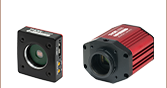
蛍光イメージング用途では、信号対雑音比(S/N比)を最大に高めるために、一般的に3種類のフィルタ(励起フィルタ、吸収フィルタ、ダイクロイックフィルタ)が、組み込まれています。当社ではこれらのフィルタをそれぞれ単品でお買い求めいただくよりもお得なフィルターセットをご用意しています。
注: 励起&吸収フィルタの筐体には推奨する光の伝搬方向を示す矢印が刻印されています。ダイクロイックフィルタでは、ビームスプリッターコーティングが付いている側に印が付いています。最適性能を得るためには光をこの印がある側から入射させる必要があります。