対物レンズ用ピエゾスキャナー
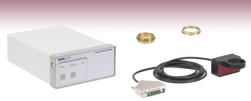
- Enables Objective Positioning and Z-Stack Acquisition with Resolution Down to 1 nm
- Travel Range: 600 µm ± 10% in Open Loop; 450 µm in Closed Loop
- Support for Heavy Objectives up to 500 g
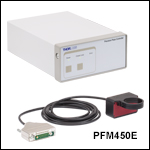
PFM450E
Piezo Objective Scanner and Paired Controller
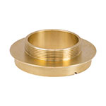
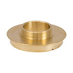
PFMA01
M32 x 0.75 Microscope Adapter
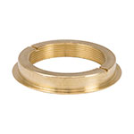
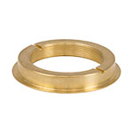
PFMA02
M32 x 0.75 Objective Adapter

Please Wait

Click for Details
対物レンズ用ピエゾスキャナPFM450Eを取り付けたBergamo顕微鏡で取得した脳深部画像(画像ご提供:RIKEN Brain Science Institute, Wako, Japan)
用途
- オートフォーカスシステム(高速タイムラプスやZスタックイメージング用)
- 光学切片(3Dイメージング用)
- 焦点距離の微調整
- 走査型干渉法
- 表面の形状測定と解析
- 半導体・ウェハ検査
Click to Enlarge
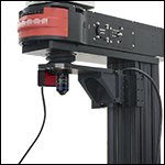
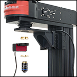
組立て後
スキャナを取り付けるには、付属のスパナレンチで真鍮製アダプタを顕微鏡の対物レンズホルダにねじ込み、アダプタ外側のフレクシャークランプを付属の2 mm六角レンチで締め付けます。 対物レンズは別の真鍮製アダプタとフレクシャークランプを用いてスキャナに取り付けます。
特長
- 25 msの整定時間(典型値)により高速データ取得および高フレームレートを実現
- 最大Ø29.0 mmの開口部が広視野対物レンズをサポート
- 静電容量フィードバックセンサにより1 nmの分解能を実現し、ドリフトをアクティブに補正
- 簡単脱着式のフレクシャークランプにより対物レンズを素早く交換可能
- 正立、倒立および回転顕微鏡との互換性
- 独立型Kinesis®またはAPT™インターフェイス、ThorImage®LSとの統合、外部電圧による制御
- ソフトウェアが重量の異なる対物レンズを容易にチューニング
対物レンズ用ピエゾポジショナPFM450Eは、焦点の精密調整およびZスタックの高速取得が可能です。 当社のBergamo® IIシリーズ多光子励起顕微鏡、共焦点イメージングシステム、Cerna®シリーズ顕微鏡プラットフォームのほか、サードパーティの顕微鏡にも対応しており、顕微鏡に内蔵されているステッピングモータを使用することなく、3次元の走査を素早く取得することができます。 内蔵型の静電容量フィードバックセンサにより、スキャナの分解能は開ループ動作時は1 nm、閉ループ動作時は3 nmで、短期および長期ドリフトをアクティブに補正します。
ピエゾ式対物レンズホルダの開口部は最大Ø29.0 mm、最大許容荷重は500 gとなっており、多光子顕微鏡や共焦点顕微鏡によく用いられる視野の広い対物レンズを簡単に取り付けられます。 ピエゾステージは、対物レンズが簡単に交換できるよう、別々のアダプタを用いて顕微鏡と対物レンズに取り付けます。 この設計により、アセンブリ内のほかの部品を取り外さないまま、対物レンズのみ取り外すことができます。 アダプタはM32 x 0.75、M27 x 0.75、SM1、M26 x 0.706、M25 x 0.75ならびにRMSネジ用をご用意しています。
スキャナは、工場で校正済みのピエゾコントローラと共に出荷されます。 対物レンズの位置制御は、独立型Kinesisまたは従来の独立型APT GUI、ThorImageLS画像取得ソフトウェア、外部供給の制御電圧によって行われます。 詳細については「ソフトウェア&外部制御」のタブをご参照ください。 コントローラにはPC制御用のUSBおよびRS-232インターフェイス、正弦波、鋸波、矩形波の駆動信号用のBNC入力端子、スキャナに内蔵の静電容量センサからの位置フィードバック信号またはピエゾ駆動電圧の比例信号用BNC出力端子が付いています。 また、DB15コネクタは、外部機器との同期に使用可能な信号を提供しています。
| Piezo Objective Scanner Specificationsa | |
|---|---|
| Open-Loop Travel Range | 600 µm ± 10% |
| Closed-Loop Travel Range | 450 µm |
| Open-Loop Resolution | 1 nm |
| Closed-Loop Resolution | 3 nm |
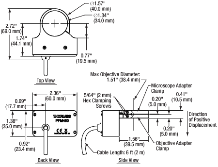
| Maximum Clear Apertureb | Ø29.0 mm (Ø1.14") |
| Maximum Objective Diameter | 38.4 mm (1.51") |
| Maximum Loadc | 500 g (1.1 lbs) |
| Settling Time | 25 ms (Typical) for 1 - 100 µm Steps |
| Resonant Frequency | 120 Hz ± 20% for 150 g Load |
| Position Linearity Error | ±0.05% |
| Tilt Angle | X-Axisd: ±35 µrad Y-Axise: ±15 µrad |
| Capacitance | 8.0 µF ± 15% |
| Cable Length | 6 ft (2 m) |
| Dimensions | 2.72" x 2.36" x 1.38" (69.0 mm x 60.0 mm x 35.0 mm) |
| Weight | 380 g (0.84 lbs) |
| Operating Temperature Range | 5 to 40 °C |
| Controller Specificationsa | ||
|---|---|---|
| Piezoelectric Output | ||
| Drive Voltage Range | -30 V to +150 V | |
| Drive Voltage Stability | 100 ppm over 24 Hours (After 30-Minute Warm-Up) | |
| Drive Voltage Noise | <0.5 mV (RMS)b | |
| Output Current | 150 mA | |
| External Input BNC | ||
| Input Voltage Rangec | -10 V to +10 V | |
| Open Loop | 1 V Input = 15 V Drive Voltage | |
| Closed Loop | 1 V Input = 45 µm Displacement | |
| Input Impedance | 10 kΩ | |
| Absolute Maximum Input Voltage | ±20 VDC | |
| External Output BNC | ||
| Output Voltage Range | 0 V to +10 V Outputs Unprocessed Feedback, Linearized Feedback, or Signal Proportional to Drive Voltage; Selectable in the Software | |
| Output Impedance | 100 Ω | |
| Minimum Recommended Output Impedance | 10 kΩ | |
| Physical Specifications | ||
| Input Powerd | Input Voltage | 24 VDC ± 5% |
| Input Current | <2 A | |
| Dimensions | 205.0 mm x 147.0 mm x 68.3 mm (8.07" x 5.79" x 2.69") | |
| Weight | 1.65 kg (3.63 lbs) | |
| Operating Temperature Range | 5 to 40 °C | |
Click to Enlarge
スキャナの寸法図面
Click to Enlarge
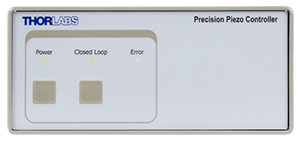
ピエゾコントローラPPC001の前面パネル
ソフトウェアで前面パネルのLED強度を強、弱、オフの3段階に設定できます。初期設定では弱モード(上の写真参照)となっています。
Click to Enlarge
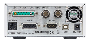
ピエゾコントローラPPC001の背面パネル
コネクタについての詳細は「ピン配列」タブをご参照ください。
ソフトウェアと外部制御
ソフトウェア
Kinesisバージョン 1.14.47
Kinesisソフトウェアパッケージには、対物レンズ用ピエゾスキャナを制御するためのGUIが付属しています。
下記もご用意しております:
- 通信プロトコル
Click to Enlarge
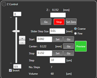
ThorImage®LSの画像取り込み設定タブ内のZ Controlパネル
Click to Enlarge
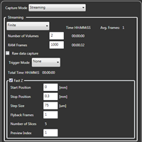
ThorImageLSの画像取り込みタブ内のFast Zパネル
スキャナは、独立型Kinesis®または従来の独立型APT™ GUI、Bergamo® IIおよび共焦点顕微鏡用ThorImage®LSソフトウェア、外部供給の制御電圧を使用して駆動できます。 また、DB15コネクタは、外部機器との同期に使用可能な信号を提供しています。制御についての詳細はKinesisおよびAPT用のマニュアル(PDFリンク)をご参照ください。
開ループ動作と閉ループ動作
対物レンズを位置制御する際は、開ループと閉ループの2種類のモードから選択できます。開ループ動作時、対物レンズの位置制御はピエゾの駆動電圧の設定で行われ、移動量が600 µm ± 10%となっています。印加された動作電圧は対物レンズのある程度の変位量に相当します。ピエゾ素子の場合、この変位量は印加電圧に対して線形変化ではなく、非線形性とヒステリシスを示しています。従って、印加電圧は単純に対物レンズの位置に転換されません。開ループ動作時において対物レンズの変位量は直接制御できませんが、変位量の測定はスキャナに内蔵されている静電容量センサにより1 nmの分解能で行うことが可能です。
閉ループ動作時、対物レンズの位置制御は変位量(µm)の設定で行われ、移動量が450 µmとなっています。スキャナに内蔵されている3 nmの分解能を有する(閉ループ動作時)静電容量センサは対物レンズの位置を測定する際に使用されています。

Click to Enlarge
Kinesis® GUIパネル

Click to Enlarge
APT™ GUIパネル
Click to Enlarge
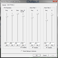
APTの「Loop Tuning」タブ。初期設定は150 gの対物レンズ用となっています。おおよその目安として、対物レンズの重量が2倍になった場合、すべてのPIDパラメータは1/2となり、ノッチフィルタは2の平方根で割られた値で設定されます。初期設定は「General」タブで回復させることができます。
独立型KinesisおよびAPT GUI
KinesisおよびAPT GUIは、開ループおよび閉ループ動作の両方をサポートします。ピエゾ駆動電圧または対物レンズの変位量は直接入力したり、出力ノブをドラッグして変更(APTのみ)して、ユーザ定義値を増加または減少させたりすることができます。
また、GUIはソフトウェアベースのPIDループチューニングも可能です。初期設定では、ほとんどの小型および中型サイズの対物レンズを安定して駆動できるようになっていますが、特定の顕微鏡と対物レンズの場合、PIDループを微調整することで、対物レンズの設定位置付近でのオーバーシュートやリンギングを低減することができるようになります。
左のスクリーンショットをご参照ください。
ThorImageLSイメージ取得ソフトウェア
ThorImageLSは、閉ループ動作をサポートしています。このソフトウェアにより、対物レンズ用スキャナの作動を当社のBergamo IIおよび共焦点顕微鏡と同じインターフェイスから制御できるため、実験統合を大幅に簡素化できます。対物レンズ用ピエゾスキャナの制御は、Capture SetupならびにCaptureタブの両方で行うことができます。右のスクリーンショットをご参照ください。
外部制御電圧
このモードでは、スキャナは開ループおよび閉ループ動作の両方をサポートします。この電圧は外部入力BNCコネクタを使用してコントローラに供給されます。開ループ動作において、入力電圧が1 V変化すると駆動電圧は15 V変化します。一方、閉ループ動作では、入力電圧が1 V変化すると対物レンズの位置は45 µm変位します。入力電圧によって決定する駆動電圧または対物レンズの変位量は、APT GUIの設定値に追加されます。合計電圧が-30 V~+150 V の駆動電圧範囲を超えても、制限によりこの範囲外の出力ができません。
通常、外部入力BNCコネクタには、正弦波、鋸波または矩形波の駆動信号を入力します。印加信号の最大周波数は波形に依存します。周期の大きな波形(つまり、合計変位量>200 µmの正弦波)の推奨駆動周波数は以下のようになります。
- 150 g以下の負荷:≤25 Hz
- 150 g~250 gの負荷:≤20 Hz
- 250 g~400 gの負荷:≤15 Hz
- 400 g~500 gの負荷:≤10 Hz
ステップサイズ50 µm以下の階段波形の場合、ステップの最低間隔は整定時間の典型値である25 msとなります。
DB15コネクタ
光刺激や電気生理学、オプトジェネティクスの用途において、コントローラ上のDB15コネクタは数種類の電気信号を提供させて、対物レンズ用ピエゾスキャナの動作を多光子イメージング用レーザ、パッチクランプ電極またはLED光源などの装置の動作と同期させます。このコネクタの詳細は、マニュアル(PDFリンク)内の追加情報A.2に記載されています。
外部制御電圧の例
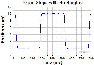
Click to Enlarge
当社のピエゾコントローラに矩形波の駆動信号を送り、16倍の生理学用対物レンズ(型番:N16XLWD-PF)を10 µm刻みで動かしました。 スキャナに内蔵されている静電容量センサによって、25 msの整定時間(典型値)以内にリンギング無しで目標の位置に達することが
示されました。
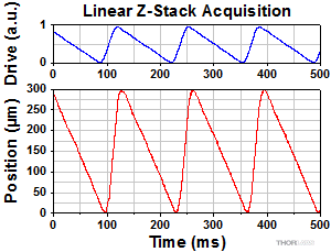
Click to Enlarge
16倍の生理学用対物レンズ(型番:N16XLWD-PF)でZスタック画像を取得するために、鋸波の駆動信号を用いました。内蔵の静電容量センサによって示されているように、300 µmの走査範囲にわたって良好なリニアリティが得られ、均等な間隔でスライス像が生成されました。
ピエゾコントローラのピン配列
ステージコネクタ

| Pin | Description | Pin | Description |
|---|---|---|---|
| 1 | HV Ground (Return) | 8 | HV Ground (Return) |
| 2 | Not Used | 9 | Not Used |
| 3 | Not Used | 10 | Stage IDb |
| 4 | Sine Wave Drive Output | 11 | Low Voltage Ground |
| 5 | Not Used | 12 | Low Voltage Ground |
| 6 | +15 V (Preamp Supply)a | 13 | Piezo ID (Legacy Stages)b |
| 7 | Low Voltage Ground | 14 | Position Sense Input (Strain Gauge) |
| Coaxial Male | Position Sense Input (Capacitive) | 15 | -15 V (Preamp Supply)a |
| Coaxial Female | HV Output |
ユーザーコネクタa
メス型DB15

| Pin | Description | Return | Pin | Description | Return |
|---|---|---|---|---|---|
| 1 | Digital Output 1 | 5, 9, 10 | 9 | Digital Ground | - |
| 2 | Digital Output 2 | 5, 9, 10 | 10 | Digital Ground | - |
| 3 | Digital Output 3 | 5, 9, 10 | 11 | For Future Use (Trigger Out) | 5, 9, 10 |
| 4 | Digital Output 4 | 5, 9, 10 | 12 | For Future Use (Trigger In)b | 5, 9, 10 |
| 5 | Digital Ground | - | 13 | Digital Input 4 | 5, 9, 10 |
| 6 | Digital Input 1 | 5, 9, 10 | 14 | 5 V Supply Output | 5, 9, 10 |
| 7 | Digital Input 2 | 5, 9, 10 | 15 | 5 V Supply Output | 5, 9, 10 |
| 8 | Digital Input 3 | 5, 9, 10 |
RS-232を介したPC制御
オス型DB9
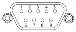
| Pin | Description | Pin | Description |
|---|---|---|---|
| 1 | Not Connected | 6 | Not Connected |
| 2 | RX (Controller Input) | 7 | Not Connected |
| 3 | TX (Controller Output) | 8 | Not Connected |
| 4 | Not Connected | 9 | Not Connected |
| 5 | Ground |
USBを介したPC制御
USB B型メス

外部入力
BNCメス型
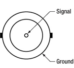
入力電圧:-10 V~+10 V
入力インピーダンス:10 kΩ
外部出力
BNCメス型

出力電圧:0 V~+10 V
出力インピーダンス:100 Ω
最小出力インピーダンス(推奨):10 kΩ
ジョイスティックコネクタ
メス型ミニDIN
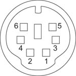
| Pin | Description | Pin | Description |
|---|---|---|---|
| 1 | RX (Controller Input) | 4 | +5 V, 100 mA Supply for Joystick |
| 2 | Ground | 5 | TX (Controller Output) |
| 3 | Ground | 6 | Ground |
Click to Enlarge
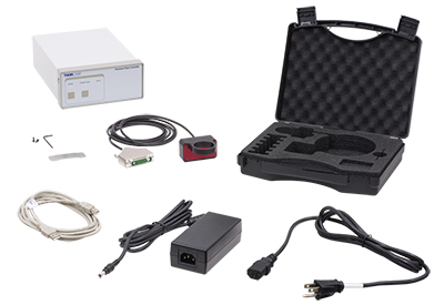
PFM450Eに付属するアイテム(写真には北米対応の電源コードが表示されています)
PFM450Eには以下のアイテムが含まれています:
- 対物レンズ用ピエゾスキャナPFM450
- ピエゾコントローラPPC001
- アダプタ取付け用スパナレンチ
- フレクシャークランプ用の予備キャップスクリュ2個ならびに2 mm六角レンチ
- 電源と電源コード(日本国内用)
- PC接続用USBケーブル
- 対物レンズ用ピエゾスキャナ、スパナレンチ、真鍮製アダプタを収納可能な保管ケース
対物レンズ用ピエゾスキャナを顕微鏡および対物レンズに接続する際に必要な真鍮製アダプタは別売りとなっています。
| Posted Comments: | |
Clemens Alt
(posted 2024-01-08 10:47:21.993) Good morning,
I am looking for a microscope objective positioner. But for our application, the axis of light propagation is horizontal, i.e., the objective is mounted horizontally and needs to move horizontally to shift the focus. Our objective weighs almost 300 g and is 90 mm long, so the center of gravity would be 10s of mm away from the mounting ring.
Can the PFM450E support such a load?
Thank you. cstroud
(posted 2024-01-10 11:16:15.0) Thank you for your enquiry. The maximum load for this stage is 500g in any orientation, and we recommend that the centre of mass is as close as possible to the stage. I will reach out to you directly to discuss your particular application. Charlie O'Mahony
(posted 2023-08-21 12:49:13.287) Hi there, I've been using the PFM450 for a couple of year now, but today it started making a crunching noise, followed by an error showing up on the controller, without any movement. The controller is probably fine, but I fear the piezo objective controller has burnt out. Firstly is there any recommendations for remedying it, but more than likely what I'm asking is it possible to price just the objective controller alone, not the piezo controller box?
Best regards,
Charlie do'neill
(posted 2023-08-22 04:46:25.0) Response from Daniel at Thorlabs. I will reach out to you directly to discuss the best options to remedy this for you as the stages are paired with their controllers. user
(posted 2023-08-08 13:11:49.07) Hi,
Can you add mounting holes for e.g. 8-32 or 1/4-20 screws to this? We do not have a microscope to which we are mounting this holder and it is not convenient to mount it as shown in your example using the circular adapter. fguzman
(posted 2023-08-14 07:51:04.0) Thanks for your enquiry. The PFM450E Piezo Objective Positioner is designed and engineered for compatibility with Thorlabs' Bergamo® II Multiphoton Microscopes, our Confocal Imaging System, our Cerna® Microscopy Platform, and third-party microscope. You could use the microscope adapters and use some other optomechanical components to use it for your application. Lee In jae
(posted 2022-01-21 00:26:12.9) Dear engineers of Thorlabs,
Hi, our labratory recently bought your product PFM450E, Piezo Objective Scanner and paired Controller.
We have two inquiries about your products.
At first, Is there any way we can see measured distance in three-digits nanometer level in closed loop mode? We are using external signal for input voltage of controller in closed loop mode. We want to see corresponding position data in more precise level such as 32.358 micrometer not 32.36 micrometer.
Secondly, can we take position data through your software(APT), or in any other ways? We are using external stepped voltage signal as a controller input. So we want to acquire position data corresponding to each step.
Thank you. DJayasuriya
(posted 2022-01-24 04:29:07.0) Thank you for your inquiry. We will get in touch with you directly to resolve your issue. DJayasuriya
(posted 2021-09-27 05:39:50.0) Thank you for your inquiry. We will get in touch with you directly. fredrik pettersson
(posted 2021-06-01 05:12:21.463) Hello,
I'm trying to figure out what this system uses as a feedback signal for detecting the substrate. Does it use a camera image? How can I set this up in a system where I replace the camera signal during measurements with an emission signal, that does not correspond the topography of the sample?
Cheers, Fredrik cwright
(posted 2021-06-02 08:32:14.0) Response from Charles at Thorlabs: Thank you for your query. The PFM450E does not have an inbuilt way of detecting a substrate but the controller used in the PFM450E has the option of being controlled by an external source supplying a voltage of -10V to +10V, which is summed with the software demanded position. If using the external input alone then 0V to +10V would correspond to the full travel range of the device. This allows the PFM450E to be controlled by another device which could detect the substrate. Soham Pal
(posted 2021-03-24 20:00:31.393) Hello,
I am a postdoc at Cavendish Laboratory, University of Cambridge and we are setting up a new confocal setup. Please provide a formal quote for PFM450E - Piezo Objective Scanner and Paired Controller, along with a M25 adapter for the microscope objective, as soon as possible. YLohia
(posted 2021-03-25 10:51:46.0) Hello, formal quotes can be requested by contacting your local Thorlabs Sales Team (sales.uk@thorlabs.com in your case) or by adding the item to your cart and selecting "Request a Quote" in the cart view. We will reach out to you directly. craig.brideau
(posted 2017-09-22 14:31:54.19) It would be nice to have a way to store the PID constants for different objectives into the system. Having to re-enter them from a notebook every time the objective is changed works but some sort of memory or storage (even in the app) would be nice. tfrisch
(posted 2017-09-26 05:37:48.0) Hello, thank you for contacting Thorlabs. PID settings can be stored in Kinesis. We will reach out to you about this functionality. kwestla
(posted 2016-07-26 14:43:12.873) Any plans on making M26 adapters for mitutoyo/motic systems? bhallewell
(posted 2016-07-29 11:22:16.0) Response from Ben at Thorlabs: Thank you for your question here. This is an option that we are looking into bringing into our range of objective adapters in the coming weeks. |

Click to Enlarge
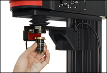
フレクシャークランプが独立した構造になっているため、スキャナを取り外さずに対物レンズを交換できます。
Click to Enlarge
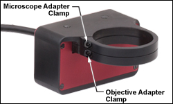
顕微鏡用および対物レンズ用アダプタは、2つの独立したフレクシャークランプを利用してスキャナに取り付けます。クランプはユニットに付属している2 mm六角レンチを用いて締め付けます。
- 「PFM450Eの発送リスト」タブ内に記載されている全アイテムが付属
- 顕微鏡用アダプタならびに対物レンズ用アダプタ(どちらも下記掲載)が必要
対物レンズ用ピエゾスキャナPFM450ならびにピエゾコントローラPPC001は、適合ペアとして工場で校正された状態で販売しております(型番PFM450E)。スキャナとコントローラには同一のシリアル番号がラベル表記されています。この対物レンズ用ピエゾスキャナを別のコントローラを使用して操作することはお勧めいたしません。
周期の大きな波形(つまり、合計変位量>200 µmの正弦波)の推奨駆動周波数は以下のようになります。
- 150 g以下の負荷:≤25 Hz
- 150 g~250 gの負荷:≤20 Hz
- 250 g~400 gの負荷:≤15 Hz
- 400 g~500 gの負荷:≤10 Hz

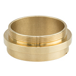
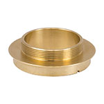
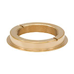
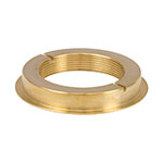
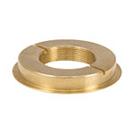
こちらの外ネジ付き真鍮製アダプタを使用してスキャナを顕微鏡対物レンズホルダに接続します。底部にはアダプタを取り付けるためのスパナレンチ用スロットが2つあります。PFM450Eに付属するスパナレンチをご使用いただけます。
M32 x 0.75ネジ付き顕微鏡用アダプタPFMA01Eは、PFMA01よりフランジ幅が厚く、当社のBergamo IIシリーズ顕微鏡をはじめとする対物レンズに窪み付きのネジがある顕微鏡にご使用いただけます。PFMA01Eは内側にも刻みがあり、多光子顕微鏡向けに集光性能を向上させています。
Click to Enlarge
PFMA01E
M32 x 0.75ネジ付き顕微鏡用アダプタ、幅広フランジ

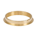
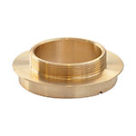
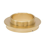
こちらの内ネジ付き真鍮製アダプタを使用してスキャナを対物レンズに接続します。 上部にはアダプタを取り付けるためのスパナレンチ用スロットが2つあります。 PFM450Eに付属するスパナレンチをご使用いただけます。
Click to Enlarge
PFMA02
M32 x 0.75ネジ付き対物レンズ用アダプタ
 Products Home


 ズーム
ズーム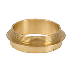
 対物レンズ用ピエゾスキャナ