 Products Home
Multispectral Imaging System
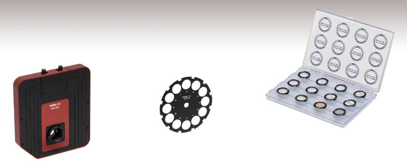
- Multispectral Imaging System with 12 Spectral Channels
- Monochrome CMOS Camera with a 2.3 MP Sensor
- Global Shutter for Imaging Fast-Moving Objects
- Filters Available for VIS, VIS/NIR, and NIR Applications
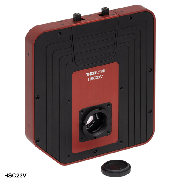
HSC23V
Multispectral Imaging System
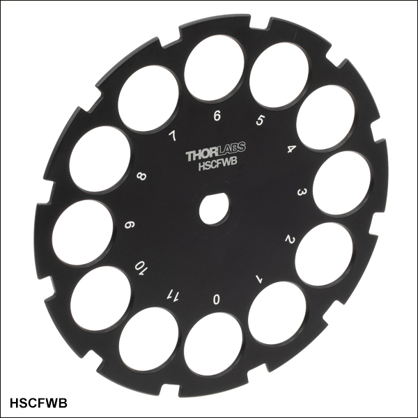
HSCFWB
Empty Filter Wheel for Multispectral Imaging System
HSCFW2
VIS/NIR Filter Kit,
10 nm FWHM


Please Wait
Building a Complete Multispectral Imaging System
A complete multispectral imaging system must include:
- 1x HSC23V Multispectral Imaging System
- 1x C-Mount Lens
- 1x Filter Kit
- 1x PC for Running the Multispectral Imaging System Software (User Supplied)
Applications
- Multispectral Imaging
- Materials Inspection
- VIS/NIR Imaging
- Machine Vision
- Security and Defense
- Medical Imaging
- Screening, Measurement, and Authentication
Features
- 1/1.2" Format, Monochrome CMOS 1936 x 1216 Pixel (2.3 MP) Sensor
- High Quantum Efficiency (71%)
- Global Shutter
- USB 3.0 Interface
- Software for Windows® 10 (64-Bit), and 11 Operating Systems
- Compatible with 30 mm or 60 mm Cage Systems
- 1/4"-20 Tapped Holes for Post Mounting
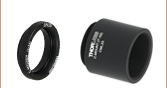
Thorlabs' HSC23V multispectral imaging system features a 1/1.2" format, monochrome CMOS sensor, and is designed to simplify the capture of spectral images (data cubes) with the help of user-configurable filter sets. The system features a 12-slot wheel (see Figure 1.2), which allows the imaging system to generate a data cube with 12 spectral channels. These data cubes enable spatial spectroscopy of a user’s samples. By selecting wavelengths relevant to an application, users can develop a measurement system capable of classifying various analytes or quantifying the response in a particular wavelength range. The global shutter of the imaging system scans the entire field of view simultaneously, allowing for imaging of fast-moving objects. The imaging system is powered by a 12 VDC, 4 A input. A DS12 power supply is provided with each imaging system; see the Shipping List tab for a complete list of items included with the device.
Click to Enlarge
Figure 1.1 The HSC23V Multispectral Imaging System used to detect pieces of nutshells (orange) among edible nuts (blue).
 Click to Enlarge
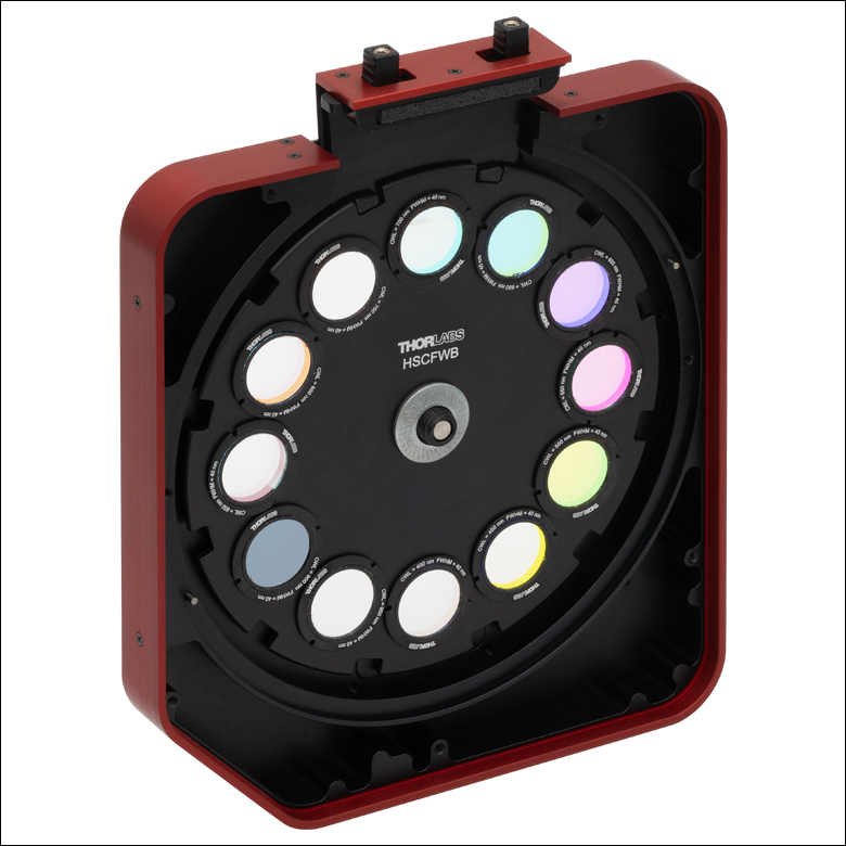
Figure 1.2 The 12-slot filter wheel of the HSC23V Multispectral Imaging System
12-Slot Filter Wheel and Filter Kits
The HSC23V imaging system features a 12-slot filter wheel, that allows customers to tailor their system to their own application. Filter kits are sold separately as sets of twelve (12) filters for various wavelength ranges (VIS, VIS/NIR, or NIR), as well as various full width at half maximum (FWHM) bandwidths. Filters from different kits can be mixed if not all filters are required from a single set to customize the system for a given application. Transmission spectra for the different filter kits can be found in the Filter Graphs tab, while more detailed specifications on each filter may be found below. An extra HSCFWB empty filter wheel may be purchased to make swapping between sets easier.
Note: The dimensions of the filters in these kits have been optimized to be compatible with the multispectral imaging system. Other Thorlabs filters are not compatible with the HSC23V Multispectral Imaging System. Only filters from the kits sold below should be used with the imaging system.
Mounting Options
The imaging system can be attached directly to our 30 mm and 60 mm cage systems via the 4-40 mounting holes on the front of the housing. Four 1/4"-20 tapped holes (two on the bottom with a spacing of 2", two on the side with a spacing of 1") on the housing provide compatibility with imperial Ø1/2" Posts, Ø1" Posts and many standard tripod mounts. For more information about mounting the HSC23V imaging system, see the Mounting Options tab.
Multispectral Imaging System Software
Each imaging system includes a USB 3.0 interface for compatibility with most computers. With the 12-slot wheel, the imaging system can generate a data cube with 12 spectral channels. This image capture is performed using the Thorlabs Multispectral Imaging System software. The software can also be used for easier replacement of filters in the filter wheel of the imaging system. Visit the Software tab to download the latest software.
Click for Details
Figure 2.2 Mechanical Drawing of the HSC23V Multispectral Imaging System
| Table 2.1 CMOS Sensor Specifications | |||||
|---|---|---|---|---|---|
| Item # | HSC23V | ||||
| Sensor Type | Monochrome CMOS | ||||
| Wavelength Range | 400 - 1000 nm | ||||
| Number of Active Pixels | 1936 (W) x 1216 (H) | ||||
| Pixel Size | 5.86 µm x 5.86 µm | ||||
| Imaging Area | 11.34 mm (W) x 7.13 mm (H) | ||||
| Optical Format | 1/1.2" (13.4 mm Diagonal) | ||||
| Peak Quantum Efficiency | 71% at 500 nm | ||||
| Shutter Type | Global | ||||
| ADCa | 12 Bit | ||||
| Max Frame Rate at Full Resolution | 40 fps | ||||
| Dark Current Compensation | Automatic | ||||
| Table 2.3 Imaging Specifications | |||||
|---|---|---|---|---|---|
| Item # | HSC23V | ||||
| Filter-to-Filter Time | 160 ms | ||||
| Exposure Time | 0 - 10000 ms (0.1 ms Increments) | ||||
| ADCa Resolution | 12 Bit | ||||
| Vertical and Horizontal Digital Binning |
1 x 1 to 5 x 5 | ||||
| Region of Interest (ROI) | 1936 (W) x 1216 (H) Pixels Max | ||||
| Table 2.4 General Specifications | |||||
|---|---|---|---|---|---|
| Item # | HSC23V | ||||
| Power Consumptiona | 2.1 W | ||||
| Operating Temperatureb | 10 °C to 40 °C | ||||
| Storage Temperature | 0 °C to 55 °C | ||||
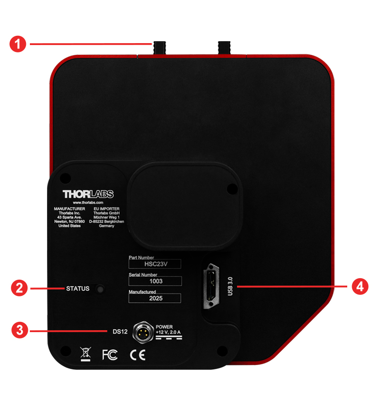
Click to Enlarge
Figure 3.2 HSC23V Multispectral Imaging System Back Panel
| Callout | Description |
|---|---|
| 1 | Filter Hatch |
| 2 | Power Indicator LED |
| 3 | Four-Pin Power Connector |
| 4 | USB 3.0 Connector |
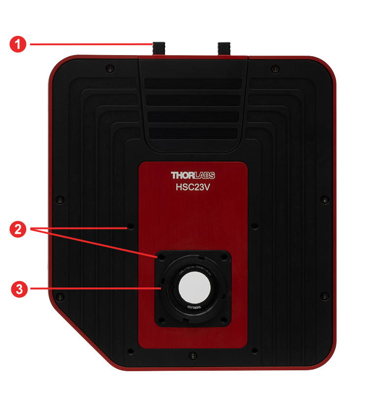
Click to Enlarge
Figure 3.1 HSC23V Multispectral Imaging System Front Panel
| Callout | Description |
|---|---|
| 1 | Filter Hatch |
| 2 | Cage Assembly Rod Holes (4-40 Tapped Holes, 8 Total) |
| 3 | C-Mount Adapter |
Figures 4.1 to 4.4 show the transmission plots for filters included in the HSCFW1, HSCFW2, HSCFW3, and HSCFW4 filter kits.
Click to Enlarge
Click for Raw Data
Figure 4.2 The plot above shows the transmission of filters in the HSCFW2 filter kit.
Click to Enlarge
Click for Raw Data
Figure 4.1 The plot above shows the transmission of filters in the HSCFW1 filter kit.
Click to Enlarge
Click for Raw Data
Figure 4.4 The plot above shows the transmission of filters in the HSCFW4 filter kit.
Click to Enlarge
Click for Raw Data
Figure 4.3 The plot above shows the transmission of filters in the HSCFW3 filter kit.
Multispectral Imaging System Mounting Features |
||||
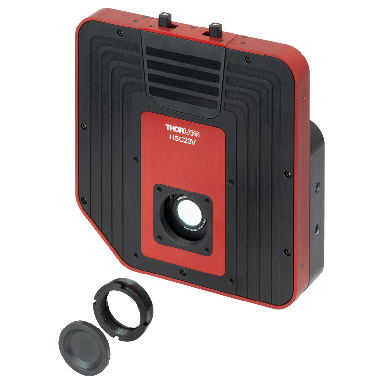 Click to Enlarge Figure 5.1 Removing the C-mount adapter and locking ring exposes the SM1 (1.035"-40) threading that can be used for custom assemblies using standard Thorlabs components. |
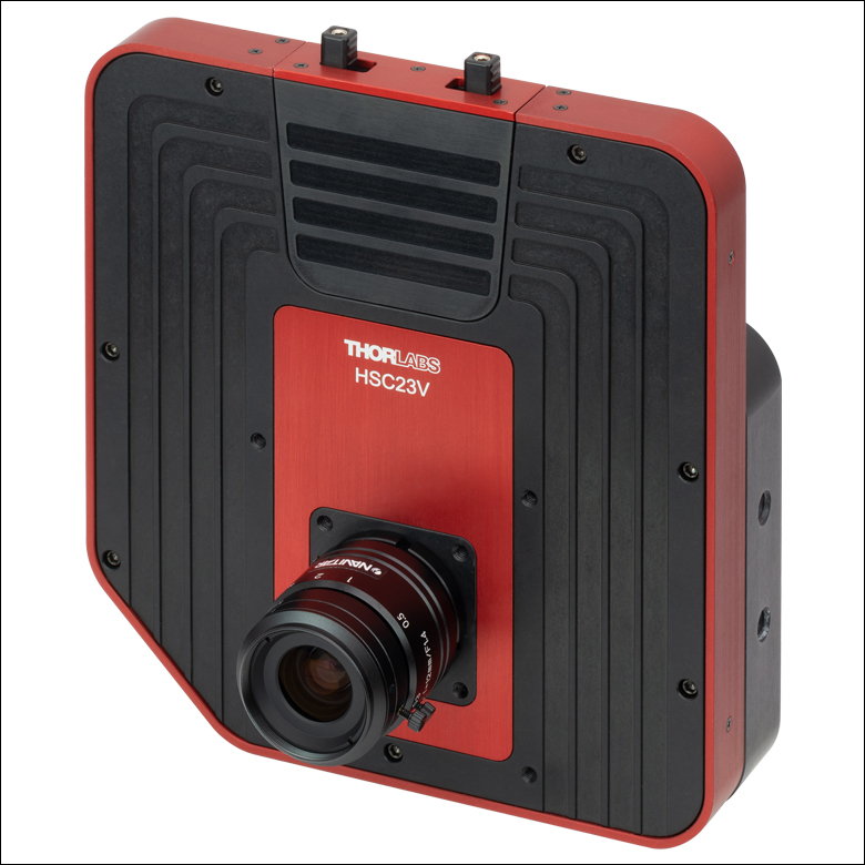 Click to Enlarge Figure 5.2 Our multispectral imaging system with an MVL12M1 Machine Vision Lens installed. |
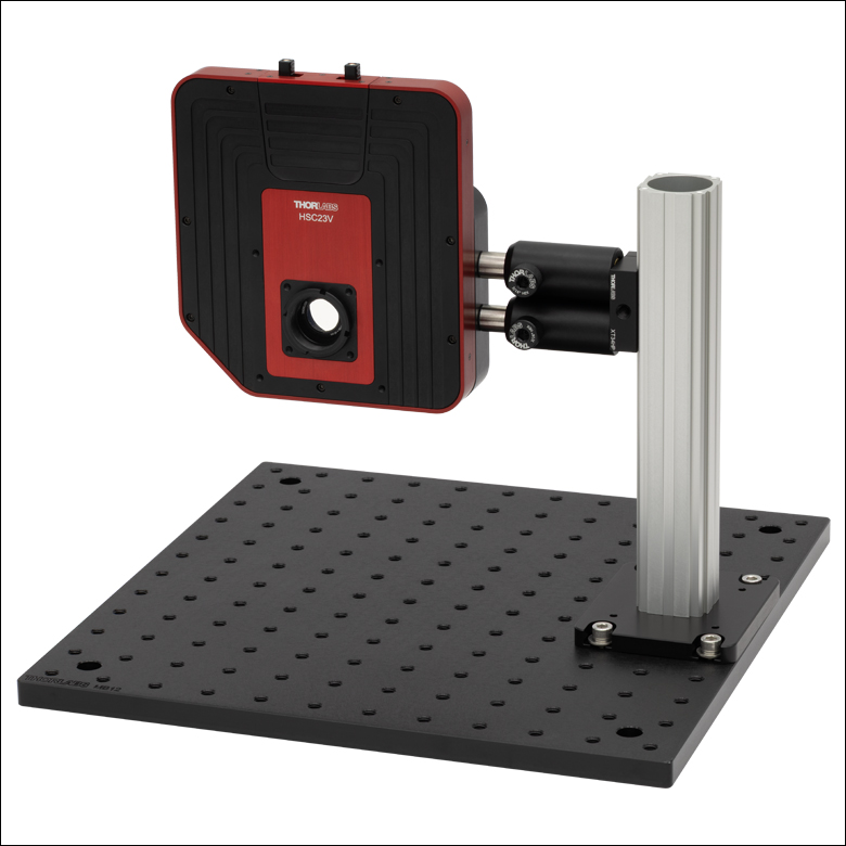 Click to Enlarge Figure 5.3 The pairs of 1/4"-20 tapped holes on the bottom and side of the imaging system can be used to provide repeatable positioning and protect against rotation of the imaging system while mounted. |
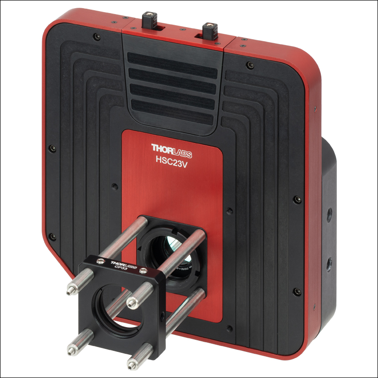 Click to Enlarge Figure 5.4 Four 4-40 tapped holes allow 30 mm Cage System components to be attached to the imaging system. Pictured is our CP33 Cage Plate with SM1 threading. |
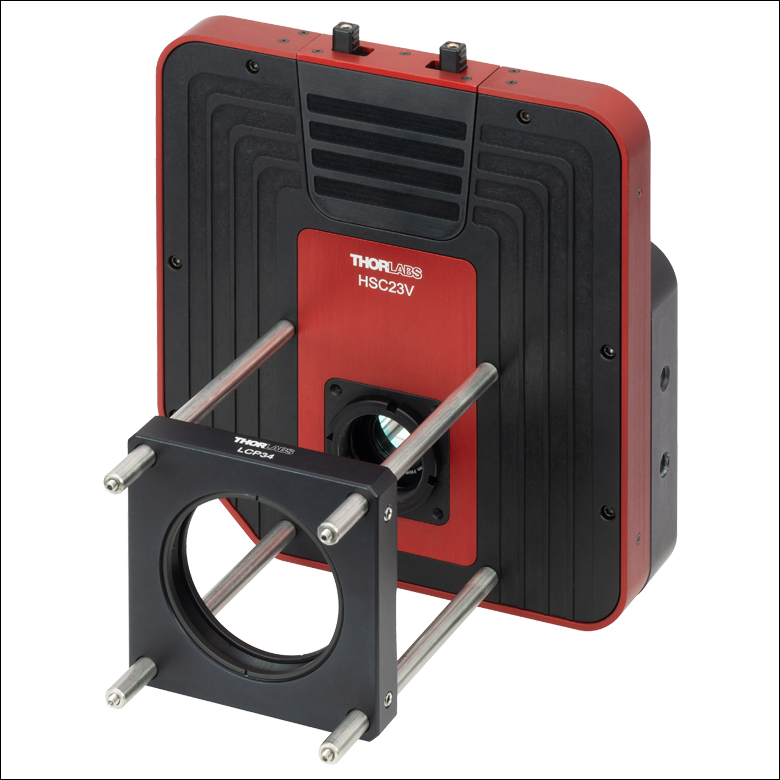 Click to Enlarge Figure 5.5 Four 4-40 tapped holes allow 60 mm Cage System components to be attached to the imaging system. Pictured is our LCP34 Cage Plate with SM2 threading. |
Software
Version 1.0.0
Click the button to visit the Multispectral Imaging System software page.
| Table 6.1 Minimum Requirements | |
|---|---|
| Operating System | Windows® 10 or Windows 11 |
| Processor (CPU) | Intel Core i5 or AMD Athlon II |
| Memory (RAM) | 8 GB |
| Hard Drive | 2 GB of Available Disk Space |
| Interface | Free High-Speed USB 3.0 Port |
The HSC23V Multispectral Imaging System software allows a user to view a Live output from the camera, capture individual images from a single filter (Single), and capture all filters in the wheel (Full Stack). Please refer to the software manual on the software page for further details on how to use these functions.
Click to Enlarge
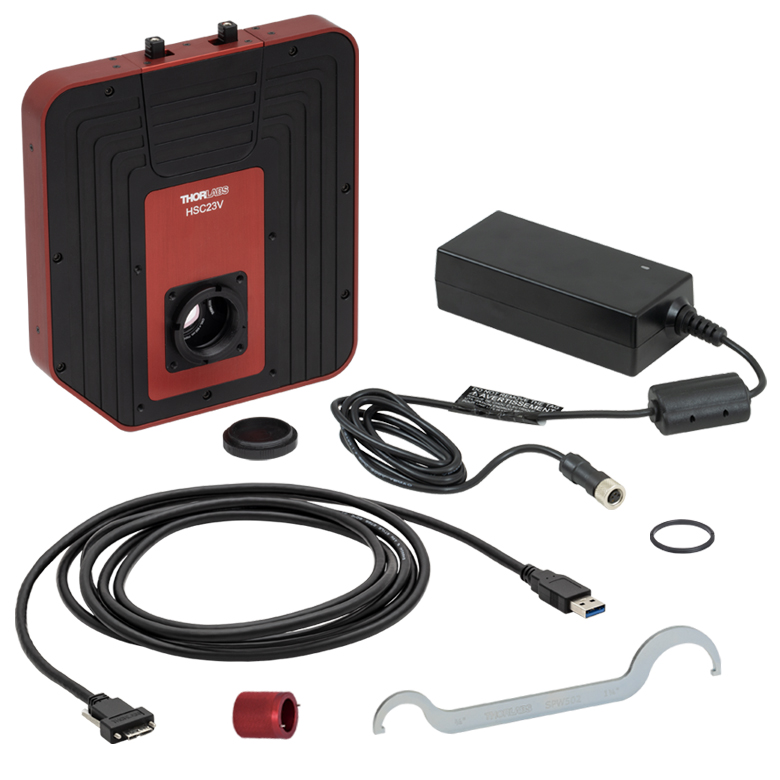
Figure 7.1 The HSC23V Multispectral Imaging System is shipped with the components shown above.
The HSC23V multispectral imaging system ships with the following components:
- HSC23V Multispectral Imaging System
- HSCFWB Filter Wheel (Mounted Inside the Multispectral Imaging System)
- DS12 Power Supply with Region Specific Power Adapter
- CABU31 USB 3.1 Type Type-A to Micro B Cable, Locking Screws, 3 m (118") Long
- SPW502 Spanner Wrench for C-Mount Adapter
- SPW909 Spanner Wrench for HSC Series Filters and Hub Nut
- SM1RR Retaining Ring

Insights:当社のサイエンティフィックカメラへのレンズの取付けについて
ここでは、当社のサイエンティフィックカメラを中心に、カメラのマウントとレンズの互換性についてご覧いただけます。
- CマウントとCSマウントのカメラとレンズに互換性はあるか
- 当社のサイエンティフィックカメラにアダプタは必要か
- フランジバックがカメラのフランジとセンサ間の距離よりも短くなり得る理由は
実験および機器についての「Insights-ヒント集」はこちらからご覧いただけます。
CマウントとCSマウントのカメラとレンズに互換性はあるか
Click to Enlarge
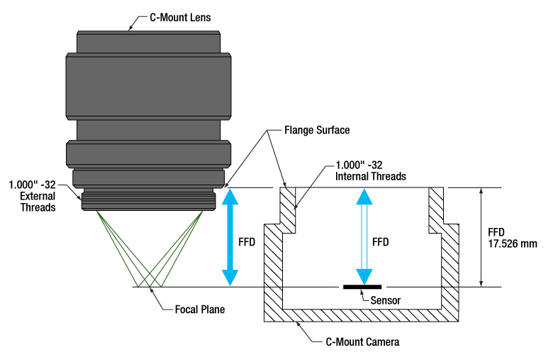
Figure 194A Cマウントのレンズとカメラのフランジバックは同じで、17.526 mmです。そのためレンズを通る光は必ずカメラのセンサ上に焦点を結びます。どちらのコンポーネントにも1.000"-32ネジが付いており、これらは「C-マウントネジ」とも呼ばれます。
Click to Enlarge
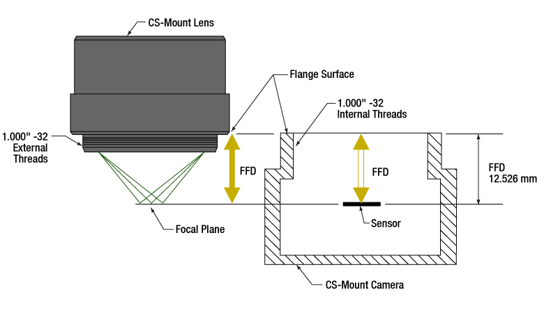
Figure 194B CSマウントのレンズとカメラのフランジバックは同じで、12.526 mmです。そのためレンズを通る光は必ずカメラのセンサ上に焦点を結びます。1.000"-32ネジはCマウントのコンポーネントに付いているネジと同じで、これらは「Cマウントネジ」とも呼ばれます。
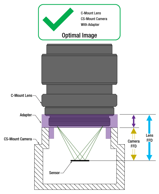
CマウントとCSマウントのカメラシステムにはどちらも1.000"-32ネジが付いていますが、この2つのマウントのフランジバック(フランジ焦点距離/FFD、フランジ焦点深度、フランジ-フィルム間距離などとも呼ばれる)は異なります。Cマウントのフランジバックは17.526 mm(Figure 194A)、CSマウントのフランジバックは12.526 mm(Figure 194B)です。
フランジバックが異なるため、CマウントとCSマウントのコンポーネントには互換性がありません。しかしアダプタを用いることによってCマウントレンズをCSマウントカメラに使用することは可能です。
CマウントとCSマウントの組み合わせ
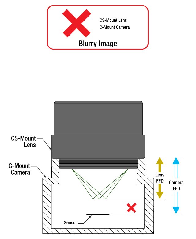
CマウントとCSマウントのネジ規格は同じですが、マウントの種類が異なるレンズとカメラを直接取り付けることはできません。直接取り付けると、フランジバックが異なるためレンズの焦点面がカメラのセンサ面と一致せず、象がぼやけます。
アダプタを使用することで、CマウントレンズをCSマウントカメラに使用することはできます(Figure 194Cと 194D)。アダプタによりレンズとカメラのセンサの間隔が5.0 mmだけ長くなり、レンズの焦点面を確実にカメラのセンサ面に一致させることができます。
一方、フランジバックの短いCSマウントレンズは、Cマウントカメラには使用できません(Figure 194E)。レンズとカメラの筐体が干渉してカメラのセンサに焦点が合う位置までレンズを近づけることができず、またレンズを近づけられるようなアダプタはありません。
レンズとカメラのパラメータを確認し、互換性のあるコンポーネントなのかどうか、アダプタが必要かどうか、また互換性を持たせる手段はないかを判断することが重要です。
1.000"-32ネジ
インチ規格のネジは、その径とTPI(1インチあたりのネジ山数)によって正確に表現されています。これらの両方のマウントのネジ径は1.000インチ、TPIは32です。Cマウント製品の普及により、1.000"-32ネジは「Cマウントネジ」と呼ばれることがあります。しかし、CSマウントデバイスにも同じネジが用いられているため、この用語は混乱を招く場合があります。
フランジバックについて
フランジバックの値はレンズとカメラの両方について与えられます(Figure 194Aと194B。レンズの場合、フランジバックはレンズのフランジ面から焦点面までの距離です。フランジ面はレンズ後方のフラットな面で、1.000"-32外ネジとその起点で交差しています。カメラの場合、フランジバックはカメラの前面からセンサ面までの距離です。 レンズがアダプタ無しでカメラに取り付けられているとき、カメラ前方のフランジ面とレンズ後方の面は接触しています。
Click to Enlarge
Figure 194E CSマウントレンズをCマウントカメラに直接取り付けると、光はカメラのセンサの手前で焦点を結びます。この場合はフランジバックを青色の矢印の距離だけ短くする必要がありますが、これはアダプタなどでは対処できません。
Click to Enlarge
Figure 194D 紫色の矢印が示す距離に相当する適切な厚さのアダプタを使用すると、Cマウントレンズの位置はCSマウントカメラのセンサから最適な位置に配置されます。これによりフランジバックが異なっても、光はカメラのセンサ上に焦点を結ぶことができます。

Click to Enlarge
Figure 194C マウントレンズとCSマウントカメラは、レンズのフランジバック(青色の矢印)とカメラのフランジバック(黄色の矢印)が異なるため、直接取り付けることはできません。光はカメラのセンサ上に焦点を結ばす、像がぼやけます。
最終更新日:2020年7月21日
当社のサイエンティフィックカメラにアダプタは必要か
Click to Enlarge
Figure 194F アダプタを使用することで、フランジバックが17.526 mmよりも短いカメラに対して、Cマウントレンズを適切な位置に配置することができます。この図は、ZeluxカメラとアダプタSM1A10Zをもとに描かれています。
Click to Enlarge
Figure 194G アダプタを使用することで、フランジバックが12.526 mmよりも短いカメラに対して、CSマウントレンズを適切な位置に配置することができます。この図は、ZeluxカメラとアダプタSM1A10をもとに描かれています。
当社のサイエンティフィックカメラKiralux™およびQuantalux®は、すべてCマウントレンズに対応するように予め設定されています。これらのパッシブ冷却方式のカメラからCマウントアダプタを取り外すと、フランジ内のSM1内ネジがご利用いただけます。サイエンティフィックカメラZeluxの取付けフランジにもSM1内ネジが付いています。またCマウントアダプタやCSマウントアダプタもご利用いただけます。
カメラ筐体にはSM1ネジが付いており、これによって当社のコンポーネントで構成されたレンズアセンブリを容易に使用することができます。アダプタを使用すれば、カメラのCマウント構成を変えることも可能です。用途に特化したレンズアセンブリを設計する場合や、そのカメラ用に設計されたものではないアダプタを使用しようとする場合には、カメラとレンズのフランジバック(FFD)が一致し、またカメラセンサのサイズが視野に適していることを確認することが重要です。
カメラとそのアダプタ
ZeluxカメラをCマウントやCSマウント規格に適合する構成に変換するための固定式アダプタをご用意しております(Figure 194Fと194G)。これらのアダプタは、パッシブ冷却方式のKiraluxおよびQuantaluxカメラに付属する調整機能付きCマウントアダプタと同様に、それぞれのカメラ専用に設計されています。
SM1ネジを1.000"-32ネジに変換するアダプタであれば、どの様なものでもカメラにCマウントやCSマウントのレンズを取り付けることが可能ですが、すべてのネジアダプタがレンズの焦点面を特定のカメラのセンサ面に一致させることができるわけではありません。場合によっては、それらの面を一致させられるアダプタが無いことがあります。例えば、こちらのサイエンティフィックカメラでは、ZeluxカメラだけがCSマウントレンズ用の構成にすることができます。
レンズの焦点面の位置は、空気中で測定されるレンズのフランジバックと、レンズとカメラセンサ間に置かれた屈折率を有する全ての光学素子との組み合わせで決定されます。レンズによって集光される光が屈折率を有する光学素子を透過すると、空気中を伝搬する場合とは異なり、焦点面はより遠い位置に移動します(この距離は算出可能)。 このアダプタは、カメラのフランジバックが短いときに、そのフランジバックの長さと、レンズとセンサ間のウィンドウやフィルタによって生じる焦点移動の両方を補正するのに十分な距離を付加するものでなければなりません。
調整機能付きCマウントアダプタ
パッシブ冷却方式のカメラKiraluxおよびQuantaluxは、SM1内ネジ付きカメラ、固定リングで固定されたウィンドウまたはフィルタ(センサの覆い)、および調整機能付きCマウントアダプタから構成されています。
調整機能付きCマウントアダプタの利点は、ウィンドウまたはフィルタと固定リングが取り付けられている時に、レンズとカメラ間の距離を1.8 mmの範囲で調整できることです。調整可能なことで、カメラのセンサ面とレンズの焦点面のミスアライメントによる様々な影響を補正することができます。それらの影響には、温度変化による材料の膨張や収縮、累積公差による位置誤差、異なる厚さや屈折率のウィンドウまたはフィルタに交換したことに伴う焦点シフトなどが含まれます。
無限遠にある物体の鮮明な像を得るためには、カメラのアダプタの調整が必要な場合があります。物体が無限遠にある場合には入射光は平行光であり、レンズのフランジバックは焦点の位置で決定されます。レンズやカメラの実際のフランジバックが意図したフランジバックと一致していない場合があり、無限遠の物体が焦点を結ぶ面がセンサ面からシフトし、そのため像がぼやけてしまうことがあります。
レンズの焦点調整をしても無限遠の物体の鮮明な像が得られない場合には、カメラのアダプタで調整してみてください。アダプタで調整することで公差や環境によるシフトが補正され、像の焦点を合わせることができます。
最終更新日:2020年8月2日
フランジバックがカメラのフランジとセンサ間の距離よりも短くなり得る理由は
Click to Enlarge
Figure 194J 屈折率の違い(θm vs. θo )により光線が屈折するため、光線の光軸に対する角度は空気中よりも媒質内で浅くなります(nm vs. no )。媒質内でdの距離を伝搬したとき、光線は hm しか光軸に近くなりません。そのため、光線はfの位置よりもΔfだけ遠い位置で光軸と交差します。
Click to Enlarge
Figure 194H 空気中を通る光線は、f.位置で光軸と交差します。光線は距離dを伝搬すると、hoだけ光軸に近くなります。空気の屈折率はno です。
| Table 194L Example of Calculating Focal Shift | |||
|---|---|---|---|
| Known Information | |||
| C-Mount FFD | f | 17.526 mm | |
| Total Glass Thickness | d | ~1.6 mm | |
| Refractive Index of Air | no | 1 | |
| Refractive Index of Glass | nm | 1.5 | |
| Lens f-Number | f / N | f / 1.4 | |
| Parameter to Calculate | Exact Equations | Paraxial Approximation | |
| θo | 20° | ||
| ho | 0.57 mm | --- | |
| θm | 13° | --- | |
| hm | 0.37 mm | --- | |
| Δf | 0.57 mm | 0.53 mm | |
| f + Δf | 18.1 mm | 18.1 mm | |
| Table 194K Equations for Calculating the Focal Shift (Δf ) | ||
|---|---|---|
| Angle of Ray in Air, from Lens f-Number ( f / N ) |  | |
| Change in Distance to Axis, Travelling through Air (Figure 194H) |  | |
| Angle of Ray to Axis, in the Medium (Figure 194J) | 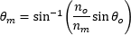 | |
| Change in Distance to Axis, Travelling through Optic (Figure 194J) |  | |
| Focal Shift Caused by Refraction through Medium (Figure 194J) | Exact Calculation |  |
| Paraxial Approximation |  | |
Click to Enlarge
Figure 194N 公差や温度の影響により、レンズとカメラのフランジバックが異なることがあります。レンズのフランジバックの方が短い場合には、無限遠の物体の像は焦点調整範囲外になります。このシステムでは焦点を合わせられないため、像はぼやけます。
Click to Enlarge
Figure 194M カメラとレンズのフランジバックが同じときは、カメラのセンサ面とレンズの焦点面は完全に一致しています。無限遠の物体の鮮明な像は、システムの焦点調整範囲の一端で得られます。
カメラとレンズのフランジバック(FFD)を決めるときは、レンズとカメラのセンサ面の間にあるのは空気のみであることを仮定しています。レンズとカメラのセンサの間にウィンドウまたはフィルタ、あるいはその両方が挿入されている場合は、カメラのフランジとセンサ面の間の距離を仕様で指定されたフランジバックよりも長くする必要があるかもしれません。ウィンドウやフィルタにより光路が屈折して焦点面がより遠い位置にシフトするため、フランジバックと同じ距離では短すぎる場合があります。
レンズとカメラセンサの間の光学素子を変更するなら、焦点面のシフト量を計算し、アライメントを保つためにレンズとカメラ間の距離を調整する必要があるかどうか判断してください。焦点の合った像を得るには、適切なアライメントは必要です。理由は、光学素子を変更することで収差やその他の影響が現れ、画像品質が許容できないレベルに低下することがあるためです。
屈折による焦点移動
光が固体媒質を通るときの光路は直線です(Figure 194H)。光が焦点に集光していく過程で、光線の光軸に対する角度
平行平面を有する屈折率の高い
光学素子を通るときの光線は、同じ距離だけ空気を通る光線に比べて、光軸に向かう速さは遅くなります。光学素子から出た後の光線の光軸に対する角度は、また光学素子を通過していないときの角度θoになります。しかし、光学素子から出る光線の位置は、光学素子を通らない場合には決して通ることのない、光軸からより遠く離れた位置になります。光学素子によって屈折された光線は光軸からより遠くなるため、光軸と交差する位置は光学素子を通らない光線よりもΔfだけ先にシフトします。光学素子の厚さが増すと、2つの光線の間は広がり、Δfは増大します。
無限遠およびそれを超えた調整
カメラシステムでは、多くのアプリケーションにおいて、無限遠の物体の高品質な像を得ることが要求されます。これらの物体からの光線は平行光で、近い物体からの光線よりもよりレンズに近い位置で焦点を結びます(Figure 194J)。カメラとレンズのフランジバックは、無限遠の位置にある物体からの光線の焦点が、カメラのセンサ面と一致するように決められています。レンズに焦点の調整範囲があるときには、その範囲の一端は無限遠の物体に、もう一端はそれよりも近い物体に焦点が合うように調整されています。
温度変化や累積公差などの影響により、レンズやカメラのフランジバックが仕様を満たさない場合があります。レンズの実際のフランジバックがカメラのフランジバックよりも短いときには、カメラのシステムは無限遠の物体の鮮明な像を得ることはできません(Figure 194N)。このオフセットは、レンズとカメラセンサの間にある光学素子を取り外したときも生じることがあります。
これを補正するために、レンズによっては焦点を結ぶ物体の位置を、無限遠を「超えて」設定できるようにしています。これは物理的な距離を意味しているわけではなく、単にレンズの焦点面をより遠くまで移動できるようにしているだけです。当社のKiralux™とQuantalux®カメラに付属する調整機能付きCマウントアダプタは、必要に応じて距離を調整できるようになっています。
レンズのフランジバックがカメラのフランジバックよりも長い場合には、無限遠の物体の像はシステムの焦点調整範囲内にありますが、本来は焦点調整範囲内にあるべき近い物体がその範囲外になります。この状況は、レンズとカメラセンサの間に光学素子を挿入することで生じる場合があります。無限遠の物体のイメージングが可能であるならば、この状況はしばしば許容されることがあります。
カメラの設計例
ハーメチックシールされたTE冷却型のCマウントQuantaluxカメラには、フランジ面とセンサ面の間に18.1 mmの固定された距離があります。しかし、Cマウントカメラシステムのフランジバック(f )は17.526 mmです。フランジバックよりも長い距離が必要であることは、ハーメチックカバーにはんだ付けされているウィンドウとセンサを覆うガラスによる焦点移動を考慮すると明白です。Table 194Lに記載されている結果は、厳密な式でも近軸近似の式でも、必要な全体の距離として18.1 mmという値が得られることを示しています。
最終更新日:2020年7月31日
| Posted Comments: | |
| No Comments Posted |

 ズーム
ズームClick to Enlarge
Figure G1.1 Our multispectral imaging system with an MVL12M1 Machine Vision Lens installed.
- Max Frame Rate: 40 fps (Full Sensor)
- Compatible with 30 mm and 60 mm Cage Systems
- SM1-Threaded (1.035"-40) Aperture with Adapter for Standard C-Mount (1.000"-32) Compatibility
The HSC23V multispectral imaging system features a 1/1.2" format, monochrome CMOS 2.3 MP sensor. The global shutter of the imaging system scans the entire field of view simultaneously, allowing for the imaging of fast-moving objects. A C-mount (1.000"-32) adapter is included for compatibility with many machine vision camera lenses and C-mount extension tubes. A replacement C-Mount adapter, SM1A10A, is available separately. Removing this adapter exposes SM1 (1.035"-40) threading that can be used to attach a Ø1" Lens Tube or SM1-Threaded Adapter. Please note that dust and debris may collect on the sensor face plate while the clear window is removed. Care must be taken when cleaning this face plate to avoid damaging the sensor.
Thorlabs’ HSC23V multispectral imaging system features a 12-slot filter wheel, that allows customers to tailor their system to their own application. The filter wheel can be removed to replace filters mounted in the wheel. For that, the filter hatch needs to be removed from the system and the front panel of the imaging system needs to be taken off. Then, the filter wheel can be removed, using the provided SPW909 spanner wrench to remove the lock nut for the hub of the wheel. Further information on filter replacement can be found in the imaging system manual. Filter kits are sold separately as sets of twelve (12) filters for various wavelength ranges (VIS, VIS/NIR, or NIR), as well as various full width at half maximum (FWHM) bandwidths. An extra HSCFWB empty filter wheel may be purchased to make swapping between filter sets easier.
The imaging system can be attached directly to our 30 mm and 60 mm cage systems via the 4-40 mounting holes on the front of the housing. Four 1/4"-20 tapped holes (two on the bottom with a spacing of 2", two on the side with a spacing of 1") on the housing provide compatibility with imperial Ø1/2" Posts, Ø1" Posts, and many standard tripod mounts. For more information about mounting the HSC23V imaging system, see the Mounting Options tab.
Click to Enlarge
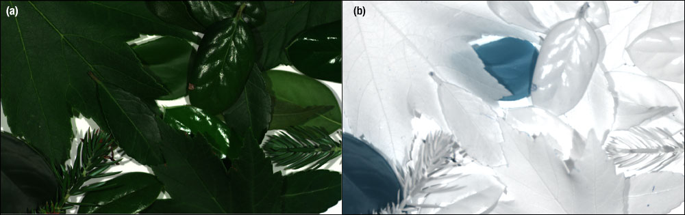
Figure G1.2 Images of foliage using the HSC23V Multispectral Imaging System with 3 different filters to generate an RGB image (a) and the HSC23V Multispectral Imaging System with an 800 nm filter (b). The left image (a) shows the leaves in RGB, where the artificial leaves are indistinguishable from natural leaves, while in the image on the right (b) the artificial leaves can be clearly distinguished (shown in blue).

 ズーム
ズームAdditional HSCFWB filter wheels are available to make swapping between sets easier, allowing users to capture multispectral images using a wider variety of Thorlabs bandpass filters. The 12-slot wheel can be populated with a pre-configured layout using off-the-shelf filter sets (available separately below) or customized to meet the needs of a user’s particular application.

 ズーム
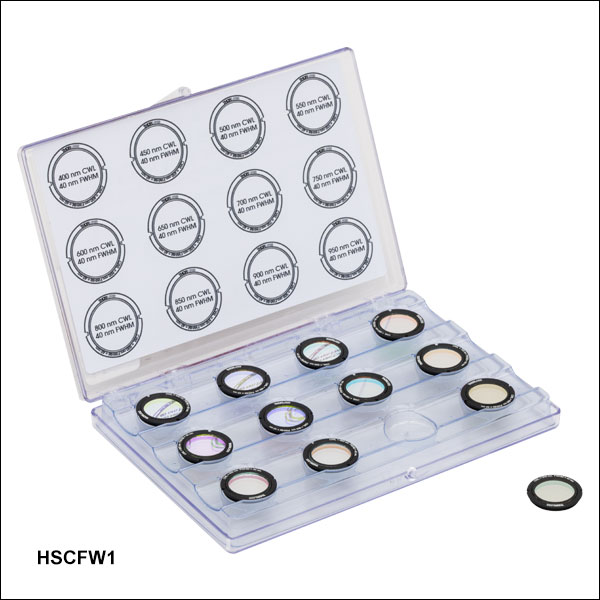
ズームThorlabs' Hard-Coated Bandpass Filter Kits contain 12 mounted hard-coated bandpass filters that can be used with the HSC23V Multispectral Imaging System to transmit well-defined wavelength bands in the VIS/NIR or NIR, while rejecting other unwanted radiation. Each filter is mounted in a M20 x 0.6-threaded Ø20.3 mm black-anodized aluminum ring that can be placed into the HSCFWB filter wheel. An extra HSCFWB filter wheel may be purchased separately to make swapping between sets easier. The filter kits come in a convenient plastic box for storage and transportation. Expand Tables G3.1, G3.2, G3.3, and G3.4 for more information on the individual filters contained in each kit.
Note: The dimensions of filters in these kits have been optimized to be compatible with the multispectral imaging system. Other Thorlabs filters are not compatible with the HSC23V Multispectral Imaging System. Only filters from the kits sold here should be used with the imaging system.
| Table G3.1 HSCFW1: VIS/NIR CWLs, 40 nm FWHM |
|---|
| Table G3.2 HSCFW2: VIS/NIR CWLs, 10 nm FWHM |
|---|


| Table G3.3 HSCFW3: VIS CWLs, 10 nm FWHM |
|---|


| Table G3.4 HSCFW4: NIR CWLs, 10 nm FWHM |
|---|
