 Products Home / 半導体レーザ用電流コントローラ(LDドライバ)、温度コントローラ、LDマウント / 光デバイスマウント / TO-Can型半導体レーザ(LD)用マウント / TO-Can型半導体レーザー用温度制御付きマウント
TO-Can型半導体レーザー用温度制御付きマウント
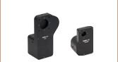
- Ø5.6 mm and Ø9.0 mm Laser Diode Mount with TEC
- Compact Housing Compatible with SM1 and 30 mm Cage System Products
- Compatible Pin Configurations: Style A, B, C, D, E, and H
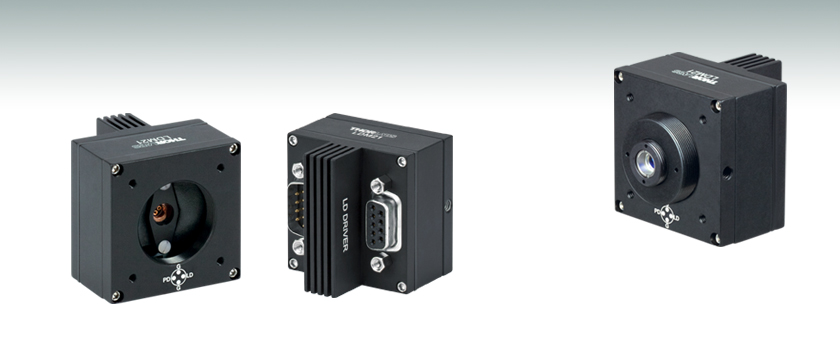
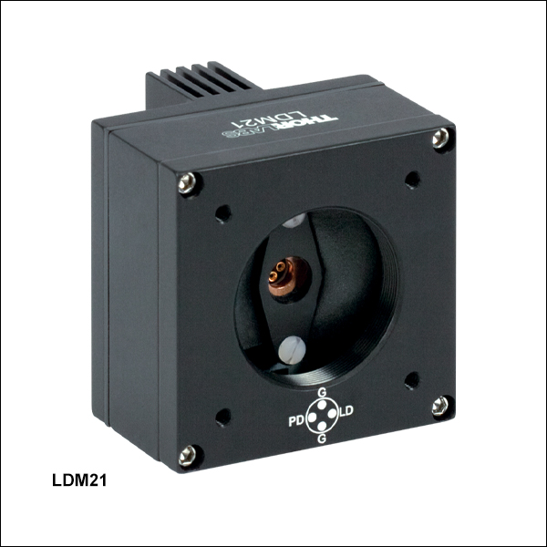
LDM21
Front
Back
Application Idea
LDM21 Mount, SM1A6T and
S05TM08 Adapters, and Aspheric Lens


Please Wait
| Item # | LDM21(/M) |
|---|---|
| Laser Diode Package | 5.6 mm and 9 mm |
| Supported Pin Configurations | A, B, C, D, E, and H |
| Maximum Laser Current | 500 mA |
| Maximum Laser Input Powera | 600 mW |
| Laser Interface | DB9 Female |
| Polarity of Laser Diode | Selectable |
| Polarity of Monitor Diode | Selectable |
| Maximum TEC Current | 2.5 A |
| Maximum TEC Voltage | 1.8 V |
| TEC Heating / Cooling Capacity | 2 W |
| TEC Interface | DB9 Male |
| Temperature Sensor | 10 kΩ NTC Thermistor |
| Temperature Range (@ 25 °C) | 20 - 30 °C |
| Dimensions (W x H x D) | 1.75" x 1.75" x 1.66" (44.5 mm x 44.5 mm x 42.1 mm) |
特長
- Ø5.6 mmとØ9 mm用小型LDマウント
- ピン配列A、B、C、D、E、Hに対応
- SM1ネジ切り加工付きで30 mmのケージシステムに接続可能
小型TEC素子付き半導体レーザーマウントLDM21/Mは、Ø5.6 mmとØ9 mmの半導体レーザーパッケージの両方でご使用いただけます。 内蔵された熱電冷却(TEC)素子および10 kΩサーミスタを使って、このマウントはケース温度を0.2°C以内に精密に維持することによって、レーザ波長を安定に保ちます。詳細と温度管理の限界については「コントローラ」タブをご参照ください。LDM21/Mは小型のため、設置場所が限られている場合の光学システムのセットアップに適したマウントです。
この製品は当社の豊富なラインナップ半導体レーザおよびTECコントローラと接続可能で、A、B、C、D、E、Hのピン配列を持つ全ての半導体レーザでお使いいただけます。 詳細については「ピン配置」 のタブをご参照ください。 マウントの前面には、標準の SM1シリーズネジが付いており、当社のØ25 mm~Ø25.4 mm(Ø1インチ)光学素子用レンズチューブに対応し、コリメートあるいは集光用光学素子を追加することができます。 背面には、レーザ電流源と TEC コントローラとの接続用のDB9コネクタが付いています。筐体にはØ12 mmまたはØ12.7 mm(Ø1/2インチ)ポスト取付け用のM4 x 0.7タップ穴が付いています。LDM21(インチ規格)にはミリ規格ポスト対応のM4内ネジが付いたアダプタAS4M8Eが付いています。
当社の標準的なオプトメカニクス部品を使用すれば、コリメート用などの光学素子を簡単に取り付けられます。 光学素子の取付けや半導体レーザを制御するための詳しい手順については、マニュアル(取扱説明書)の他に上記のタブで「コントローラ」や「LD出力光コリメート」のタブ内をご参照ください。さらなる詳細は、当社までお問い合わせください。
ピンコード
Figure 1.1 マウントLDM21/Mが対応するピンコードはA、B、C、D、E、Hです。上記は実際の配線図を表したものではありません。
Figure 2.1 対応可能ならびに非対応のピン配置
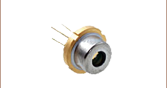
半導体レーザーピン配置
当社はUV、可視、近赤外域用途で様々な半導体レーザをご提供しています。多くの半導体レーザーパッケージではモニタ用フォトダイオードを内蔵しています。電気接続端子の配置はパッケージの内部配線によって異なります。当社ではこの異なるピン配置をFigure 2.1のようにピンスタイルA~Hに分類しています。ご提供している半導体レーザのピン配置のスタイルは、当社ウェブサイトに掲載している仕様表ならびに半導体レーザとともに発送する仕様書にも記載されています。半導体レーザーパッケージのピンスタイルは、Figure 2.1のピン配列図でご確認いただけます。ピンスタイルの種類、ピン配置、そして下記情報をもとに半導体レーザに正しく電源供給を行ってください。
Figure 2.2のようにLDM21/Mの前面には半導体レーザの向きが刻印されています。
マウントLDM21/Mの互換性
半導体レーザーマウントLDM21/Mは、Ø5.6 mm、Ø9 mmでピン配置がA、B、Cのすべての3ピン型半導体レーザーパッケージに対応します。このピン配置のパッケージには半導体レーザとモニタ用フォトダイオードが内蔵されており、半導体レーザ(LD)用のピン、フォトダイオード(PD)用のピン、共通の接地ピンがあります。
Figure 2.2 LDM21/Mは標準的な
4ピン配置です
このマウントは、ピンスタイルE、Hのモニタ用フォトダイオードが付いていない半導体レーザにも対応します。 これらのレーザは3ピン型のパッケージでFigure 2.1のように半導体レーザ用のピンと接地ピンが3ピン中に含まれています。
マウントLDM21/Mは、当社が現在ご提供しているピンスタイルD(Figure 2.1参照)の4ピン型半導体レーザすべてにも対応します。ピンスタイルA、B、Cと同様に、スタイルDの半導体レーザーパッケージには半導体レーザとモニタ用フォトダイオードが付いています。ただし、スタイルDのパッケージについてはフォトダイオードはケースに接続していません(フロートの状態です)。
マウントLDM21/Mは、スタイルFとGの半導体レーザには接続できません。これらのピンスタイルは、マウントLDM21/M内では使用できないピン配列となっております。これらのピン配列に対応する高出力半導体レーザ用マウントはこちらをご覧ください。
LDM21/Mの電子部品の構成と動作の詳細については、取扱説明書をご参照ください。
| Label | Descriptiona |
|---|---|
| GND | Ground |
| LD | Laser Diode Cathode or Anode |
| PD | Photodiode Cathode or Anode |
LDドライバ
9ピン、D型、メス
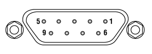
| Pin | Signal | Description |
|---|---|---|
| 1 | Interlock (LDC Specific) | This pin is the input to the Interlock Circuits. When using Thorlabs LDCs no external circuitry is required. |
| 2 | Photodiode Cathode | This pin is connected to the 9 o'clock pin on the laser socket when the PD Polarity Switch is set to AG1. It is attached to ground and the 12 o'clock and 6 o'clock pins on the laser socket when the PD Polarity Switch is set to CG2. |
| 3 | Laser Ground (Case) | This pin is connected to the 12 o'clock and 6 o'clock pins on the laser socket and corresponds to the settings of the LD and PD polarity switches. i.e. If the LD and PD switches are set to AG then this pin grounds the Anodes of the laser and photo diodes. |
| 4 | Photodiode Anode | This pin is connected to the 9 o'clock pin on the laser socket when the PD Polarity Switch is set to CG. It is attached to ground and the 12 o'clock and 6 o'clock pins on the laser socket when the PD Polarity Switch is set to AG. |
| 5 | Interlock Return | This pin is the return side of the Interlock circuitry. Pin 1 and 5 are shorted internally in the LDM21. |
| 6 | N.C. | Not Used. |
| 7 | Laser Diode Cathode | This pin is connected to the 3 o'clock pin on the laser socket when the LD Polarity Switch is set to AG . Otherwise it is floating. |
| 8 | Laser Diode Anode | This pin is connected to the 3 o'clock pin on the laser socket when the LD Polarity Switch is set to CG . Otherwise it is floating. |
| 9 | N.C. | Not Used. |
TECコントローラ
9ピン、D型、オス
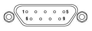
| Pin | Signal | Description |
|---|---|---|
| 1 | N.C. | Not Used |
| 2 | +Thermistor | The 10 kΩ at 25 °C NTC thermistor (provided for temperature feedback). |
| 3 | -Thermistor | The thermistor return pin. |
| 4 | +TEC | This pin is connected to the positive terminal of the TEC element. |
| 5 | -TEC and TEC Lockout (-) | This pin is connected to the negative terminal of the TEC element. |
| 6 | N.C. | Not Used. |
| 7 | AD592(-) | The negative terminal of the AD592 temperature transducer. When using Thorlabs TEDs no external circuitry is required. To use this device with third party controllers it must be properly biased. Refer to Analog Devices AD592 Data for application information. |
| 8 | N.C. | Not Used. |
| 9 | AD592(+) | The positive terminal of the AD592 |
半導体レーザ電流コントローラ
半導体レーザの電流コントローラは、半導体レーザの仕様と用途を考慮してお選びください。当社では、低出力(低電流かつ低電圧)から高出力(高電流かつ・または高電圧)まで様々な半導体レーザーコントローラをご用意しております。また半導体レーザ駆動電流コントローラと温度コントローラが1つまたはセットになった製品もいくつかご提供しています。温度コントローラについては下記のTECコントローラのセクションをご覧ください。
当社のLDC2xxCシリーズのコントローラは、多くの半導体レーザに適用できます。LDC200CVは、特にVCSELに適した設計がなされており、扱いが比較的難しいVCSELを安全に動作させることができます。また、LDC201CUは超低ノイズ(<0.2 μA RMS)の電流供給を特長としています。青色または短波長の半導体レーザを駆動するためによく用いられる高電圧用途には、コントローラLDC202C、 LDC205CまたはLDC210Cをご検討ください。高出力半導体レーザの駆動用には、それぞれ駆動電流が2 Aまたは4 Aの LDC220CおよびLDC240Cをお使いいただけます。高電流対応の製品(5 Aと 20 A)、T-Cubeに接続可能な製品やラックマウント型の製品もあります。これらのコントローラはすべて同じように動作します。こちらではLDC2xxCシリーズのコントローラについてのみご説明いたします。
TECコントローラ
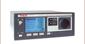
当社ではTECコントローラとして、スタンドアローン型、半導体レーザーコントローラ/温度コントローラ一体型やセットなど、様々な種類および形態でご提供しております。TED200Cのベンチトップ型温度コントローラは、半導体レーザーマウントLDM21にマウント済みの半導体レーザの温度管理に適しています。この製品の特長は幅広い動作温度範囲と、12 Wの冷却、そして高い温度安定性です。さらに大きな冷却力と高い温度安定性が必要な場合には、225 Wの温度コントローラTED4015 をご使用いただけます。
こちらのマウント内のTEC素子は、ユニット側面のメス型DB9コネクタを介して温度コントローラに接続可能です。他のコネクタータイプに対応した温度コントローラに対しては、アダプターケーブルのご用意があります。当社以外のメーカのコントローラをご使用の場合、取扱説明書に記載されているピン配列や詳細をご参照ください。TECコントローラは手順通りに使用し、マウント内蔵のTEC素子がオーバードライブしないようご注意ください。
TECの動作限界
マウントLDM21は、25 °Cの固定温度で動作されることを想定して設計されていますが、半導体レーザの入力パワー(LD電流 x LD電圧)が、周囲温度と入力パワーの関係を表わした安全動作曲線(Figure 4.1)で示された数値を超えない範囲であれば、20 °Cまでの低温でも動作が可能です。なお、LDM21駆動の際には、入力パワーが600 mWを超えること、20 °C未満の温度に設定すること、または周囲温度が 35 °Cを超える環境で動作することは推奨いたしません。安全動作領域(Figure 4.1の曲線の下の領域)から外れてLDM21を動作することは、 半導体レーザに損傷を加える可能性があります。
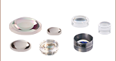
半導体レーザに合ったコリメート用レンズと非点隔差補正光学素子の選択
半導体レーザ(LD)の出力は大きく拡散するので、コリメートには光学素子が必要となります。非球面レンズは、球面収差を補正する能力に優れているので、コリメート後のレーザ光線の径を1~5 mmとしたい場合は非球面レンズを用いるのが一般的です。 希望のビームの大きさと透過帯域は、使用するレンズに依存するため、半導体レーザ出力光をコリメートするためには、最適な非球面レンズを選ぶことが不可欠です。 半導体レーザのコリメート光の大きさを計算するに当たって、まず拡散について理解する必要があります。
端面発光半導体レーザの出力にもまた、かなりの非点隔差があります。ビーム発散角は、平行および垂直方向において異なり、楕円ビームをもたらします。 コリメート後にアナモフィックプリズムペアやシリンドリカルレンズを挿入することによって、この楕円率を補正することができます。半導体レーザ出力の拡散は、チップの2軸の「ビーム発散角(FWHM) - 平行」と「ビーム発散角(FWHM) - 垂直」により典型値として規定されています。 半導体レーザは、ロットごとにバラツキがありますが、典型的な発散角を用いることにより、より多くの用途に適合できます。
ここでは目的の用途に合った適切なレンズを選定する上で重要な仕様について簡単な例をあげてご説明します。
例:785 mm、25 mWの半導体レーザL785P25、コリメート後のビーム径:Ø3 mm
ステップ1: レーザ出力光をコリメートする
半導体レーザ L785P25の仕様書によれば、光線の垂直と平行方向における典型的な発散角はそれぞれ30oと8oです。大きい(垂直の)ビーム発散角はFigure 66Aに示されています。小さい(平行の)ビーム発散角はFigure 66Bに示されています。 2軸のこの非点隔差または非対称性により、光が発散するにつれて、光線は楕円形になっていきます。 コリメートの段階でできるだけ多くの光を集光するためにどの計算においても2つの発散角のうち、大きな方の数値を使ってください(この場合は30o)。
注: 平行と垂直表記は、半導体レーザの接合面に対して規定されます。
Figure 66A L785P25からの垂直方向のビーム発散角、スタイルBのLD
Figure 66B L785P25からの平行方向のビーム発散角、スタイルBのLD
Figure 66Aと66Bでは、LDは半導体レーザ、 と
と  は、それぞれ平行および垂直方向のビーム径、
  と
と は、それぞれ平行および垂直方向の発散角を表します。 Figure 66Aと66Bの中の切り込み(Notch)は、パッケージ内部の半導体レーザの方向を決定するために利用できます。半導体レーザは通常、切り込み(Notch)に対し平行方向に設置されます。しかし、特に異なる半導体パッケージについては、多くの例外があります。 半導体レーザとその発光方向には、十分にご注意ください。
Ø3 mmのコリメート後のビーム径を得るために必要なレンズの焦点距離を計算する上で、下記の計算式を使用できます。
 は焦点距離で 、目的とする垂直方向のビーム径 をもたらすLDとレンズ間の距離です。 30oの発散ビームをØ3 mmのコリメート光にコリメートするために、必要なレンズの焦点距離は、 = 5.6 mmです。
計算式では、目的とする(垂直方向の)主軸径を得るための焦点距離を計算します。 次に、式から得られた焦点距離に最も近い焦点距離の非球面レンズを選定します。 ここで、レンズの直径は、目的とする主要軸のビーム径よりも大きくなければならないことにご注意ください。
当社では数多くの種類の非球面レンズをご用意しています。 この使用例における理想的なレンズは、-B ARコーテイングの施されたモールドレンズで焦点距離が約5.6 mmのものとなります。C171TMD-B (マウント付き)または354171-B (マウント無し)の非球面レンズの焦点距離は6.20 mmです。次に半導体レーザの開口数(NA)がレンズのNAより小さいことを確認してください。これは半導体レーザの放出する光がレンズに蹴られることを防ぐためです。
0.30 = NALens > NADiode ~ sin(15) = 0.26
Figure 66C 楕円形から円形のビームに変換するための、アナモフィックプリズムペアと光線追跡図
実際の焦点距離と主要軸の発散角を使って上記の式を解くことにより、実際の主要軸のビーム径が得られます。
ステップ2:非点隔差を補正する
Figure 66Aと66Bに示されている通り、端面発光半導体レーザからの発光には非点隔差があります(2つの異なる軸に対して非対称です)。 これを補正し円形ビームにするには、コリメート後にアナモフィックプリズムペアやシリンドリカルレンズを使って、短軸径を拡大することが必要です。 Figure 66Cは、目的とする対称ビームを得るために、短軸の楕円ビームを拡大しているアナモフィックプリズムペアを示しています。
![]() = 6.20 mm = 8oを使って式を解きます。この結果、短軸径 = 0.9 mmが得られます。 と を比較すると、短軸ビームを3.5倍率拡大する必要があることが分かります。この3.5倍拡大は、マウント付きアナモフィックプリズムペアPS881-Bを使って行うことができます。
= 6.20 mm = 8oを使って式を解きます。この結果、短軸径 = 0.9 mmが得られます。 と を比較すると、短軸ビームを3.5倍率拡大する必要があることが分かります。この3.5倍拡大は、マウント付きアナモフィックプリズムペアPS881-Bを使って行うことができます。
レンズチューブの取付け
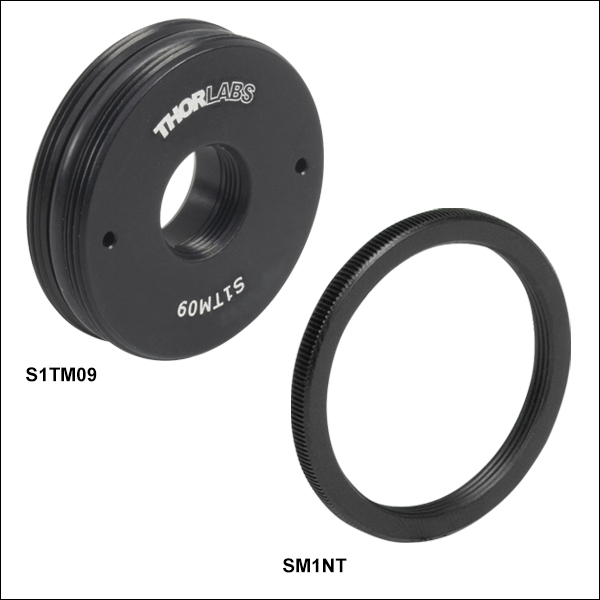
マウント付き非球面レンズには、当社のアダプタSM05TxxまたはS1TMxxをご使用いただけます。レンズが半導体レーザに接触しないようご注意ください。アダプタSM05TxxはSM1-SM05変換アダプタSM1A6Tをお使いいただく必要があります。
マウント無しの非球面レンズは、アダプタLMRAxxにエポキシ樹脂で接着することができ、その後SM1-SM05変換アダプタSM1A6T に取付けることができます。 アダプタのSM1ネジ切り部は、レンズ/マウント/アダプタのアセンブリを半導体レーザーマウントの前面プレートに装着するのに利用できます。 アダプタSM1A6Tには10 mmの取付け部があるため、当社の非球面レンズのほぼすべてにお使いいただけます。
上の例では、マウント付きレンズC171TMD-BにM8 x 0.5 のネジ切りが付いているので、ネジ付きアダプタS05TM08が必要となります。M8-SM05変換アダプタS05TM08は、SM1-SM05 変換アダプタSM1A6T を使って、半導体レーザーマウントに取り付けることができます。 アダプタS05TM08とSM1A6Tの両方を調整することで、半導体レーザとレンズの間の距離を補正することができます。
マウント無しの非球面レンズ354171-Bをご使用の場合は、最初にアダプタLMRA5に接着する必要があります。 その後、SM1-SM05アダプタSM1A6T に取り付けることができます。 ここでも、非球面レンズの調整はアダプタLMRA8とSM1A6Tで行うことができます。
ケージシステムへの取付け
焦点距離が8 mm以上のマウント付きまたはマウント無しの非球面レンズは、当社の30 mmケージシステムを用いてケージに取り付けることができます。 ケージロッドは、半導体レーザーマウントの前面プレートに直接取り付けることができます。ケージプレートCP33/Mを用いると、マウント付き非球面レンズが取付けられたアダプタS1TMxxを保持したり、マウント無し非球面レンズが接着されたアダプタLMRAxxをアダプタSM1A6Tに取付けて保持したりすることができます。
より長距離の移動調整には、移動量13 mmの移動ステージCT1A/Mをご使用いただけます。 CT1A/Mには直線移動距離13 mm、最小目盛10 µm(0.001インチ)のマイクロメータが付いています。キャリッジの最小移動量は約1 µmです。
アナモフィックプリズムペアの取付け
半導体レーザからの出力ビームの非点隔差は、アナモフィックプリズムまたはシリンドリカルレンズのいずれかを使って補正できます。 上記の例で選定されたように、円形ビームプロファイルを生成するには、3.5倍率のマウント付きアナモフィックプリズムペア(PS881-B)が必要になります。 マウント無しのプリズムを使用することも可能です。
マウント付きアナモフィックプリズムペアPS881-Bは、出光端にSM05ネジ切り加工ほどこされているか、あるいはSM1レンズチューブ内部に取り付けられています。 アナモフィックプリズムペアの入力光および出力光は互いに相殺し合うため、プリズムは別のケージまたはレンズチューブの光軸に取り付ける必要があります。
Video Insights(How-to動画集):TO-Can型半導体レーザのセットアップ
TO-Can型半導体レーザをマウント内に取り付けて、温度と電流の制御下で動作するように設定する際、誤ってレーザに損傷を与えたり破損したりする可能性が多くあります。動画では、人体と半導体レーザを損傷の危険から守る方法を順を追って説明しています。
そのほかにも実験室でお使いいただけるヒント、工夫や方法などの動画がこちらからご覧いただけます。また、ウェビナーでは、当社の様々な製品に関する理論や実用的な事柄などをご紹介しています。
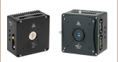
| Laser Diode Mount Selection Guide | |||||||
|---|---|---|---|---|---|---|---|
| Item # | LDM38(/M) | LDM56(/M) | LDM56F(/M) | LDM90(/M) | LDM21 | LDM9T(/M) | |
| Click Photo to Enlarge |  | 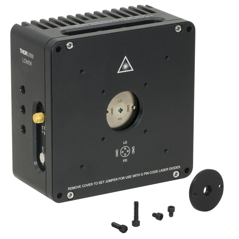 | 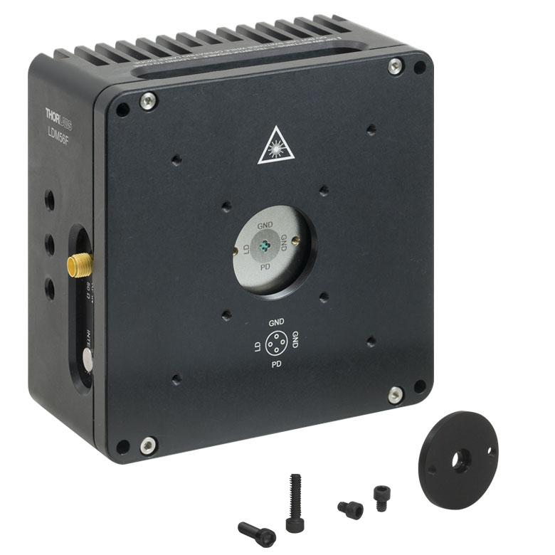 | 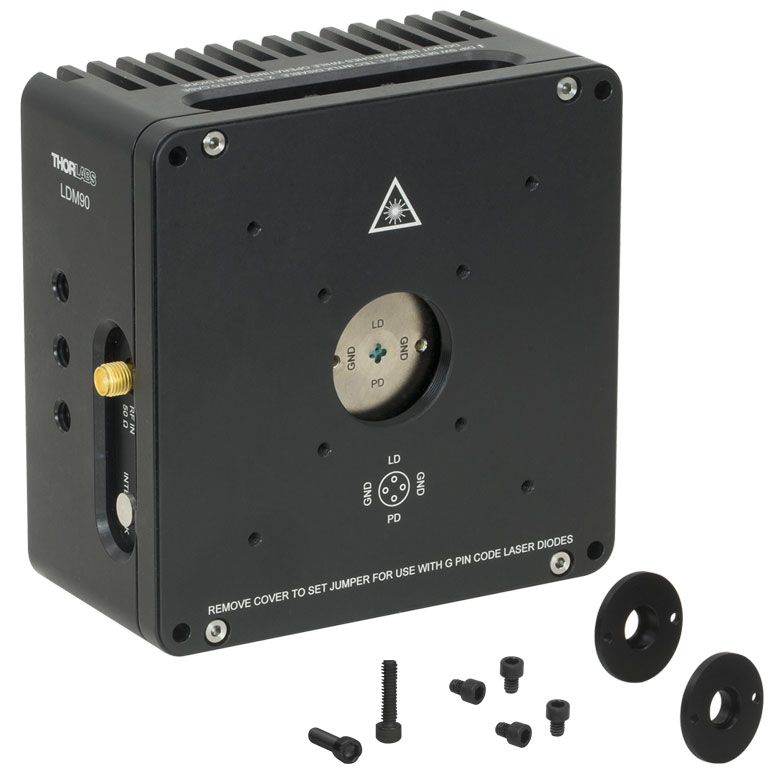 |  | 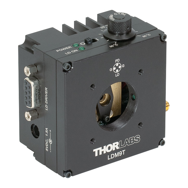 | |
| Laser Diode | |||||||
| Supported Laser Diode Package(s) | Ø3.8 mm | Ø5.6 mm | Ø5.6 mm | Ø9 mm | Ø5.6 mm and Ø9 mm | Ø5.6 mm and Ø9 mm | |
| Supported Pin Configuration(s) | G | A, B, C, D, E, Ga, H (Switch Selectable) | F and G (Switch Selectable) | A, B, C, D, E, Ga, H (Switch Selectable) | A, B, C, D, E, and H | A, B, C, D, E, G, and H (Some Modification Necessary for G Style)b | |
| Maximum Laser Current (Tambient = 25 °C) | 1 A | 2 A | 500 mA | 200 mA | |||
| RF Modulation Frequency Rangec | 100 kHz to 500 MHz | 100 kHz to 600 MHz | N/A | 200 kHz to 1 GHz | |||
| Temperature Controller | |||||||
| TEC Heating/Cooling Capacity (Tambient = 25 °C) | 8 W | 8 W | 2 W | 0.5 W | |||
| Temperature Adjustment Range | - | 0 to 70 °C | 20 to 30 °C | ||||
| General Specifications | |||||||
| Laser Interface | DB9 Female | ||||||
| TEC Interface | DB9 Male | N/Ad | |||||
| Compatible Current and Temperature Controllers | LDC Series and T-Cube LD Controllerse, ITC Series Combined LD/TEC Controllersf, and Temperature Controllersf | LDC Series and T-Cube LD Series Controllerse | |||||
| Mounting Features | Imperial Mounts | 1/4"-20 Tapped Hole (9 Places) | 8-32 Tapped Holeg (4 Places) | 8-32 Tapped Hole (3 Places) | |||
| Metric Mounts | M6 x 1.0 Tapped Hole (9 Places) | N/A | M4 x 0.7 Tapped Hole (3 Places) | ||||
| Accommodations for Collimating Optics | SM1 (1.035"-40) Series Internal Thread; LDMXY Flexure Adapter (Sold Separately) | SM1 (1.035"-40) Series Internal Thread | |||||
| Cage System Compatibility | 4-40 Tap (8 Places) for 30 mm and 60 mm Cage Systems | 4-40 Tap (4 Places) for 30 mm Cage System | |||||
| Dimensions | 4.00" x 4.00" x 2.07" (101.6 x 101.6 x 52.6 mm) | 1.75" x 1.75" x 1.66" (44.5 x 44.5 x 42.1 mm) | 3.09" x 2.89" x 1.79" (78.5 x 73.3 x 45.5 mm) | ||||
| Posted Comments: | |
Marina Benito-Parejo
(posted 2025-07-03 09:21:49.427) I'm using a third party controller with LDM21, and pin 1 (interlock) and pin 5 (interlock return) are not connected con mount side. I'm also using LDM56 with the same third party driver, what should I do with pins 6 and 9?? Pins 1 and 5 are ok NC??
Thanks ksosnowski
(posted 2025-07-03 12:31:53.0) Hello Marina, thanks for reaching out to us. Pin 1 and 5 do not need to be connected to use the LDM21 with third party drivers. These pins just provide a return loop for the interlock signal of our benchtop laser drivers, but they do not interface with the laser driving pins at all. With LDM56, this pair of pins also is used to power the laser status LED on the mount, but they are not required for operation with third party drivers. If they are used, the interlock current needs to be limited to 10mA, and the LDM56 TEC lockout switch must be set to bypass. Laser pins 6 and 9 are disconnected on LDM21 and do not need to be used. On LDM56, pins 6 and 9 can be used by our drivers to monitor the laser forward voltage during operation. Sandro Heuke
(posted 2025-06-16 13:06:34.73) Dear Sir or Madame,
can I use your LDM21 also for mounting PDs? I am desperately searching for a TEC cooled PD mount where I can plug and play different PD such as your FGA01. If the LDM21 is not suited, I would be more than pleased if you would consider adding a new product that does power up the PD (reverse bias), cools the PD and allows for extraction of the photo-current with potential amplification. I expect that you would have >1000 orders per year. Best regards,
Sandro jdelia
(posted 2025-06-19 04:36:48.0) Thank you for contacting Thorlabs. We do not recommend mounting a photodiode inside the LDM21 as it is only rated for laser diodes. That said, I have reached out to you directly via email to clarify your suggestion and discuss your application further. Andrea Sardella
(posted 2023-10-05 06:27:42.633) Which is the swithc configuration to support a style D laser diode? Do you have an electrical schematic ? cdolbashian
(posted 2023-10-18 04:59:59.0) Thank you for reaching out to us with this inquiry. Information regarding the configuration of the device with respect to the pin configuration of the diode, can be found within the manual and diode spec sheet. I have reached out to you directly to assist in locating such documents on our website. In general, they will be located by clicking the red "Docs" icon on the respective product page. Hugo Pereira
(posted 2022-10-27 09:14:32.4) I have a TO-46 package VCSEL and I am looking for a TEC mount. Does Thorlabs provide a solution for these packages, such as an adapter, or is able to produce a custom mount compatible with my laser diode? ksosnowski
(posted 2022-10-27 04:47:12.0) Hello Hugo, thanks for reaching out to Thorlabs. Currently we have not designed any TEC actively-cooled mounts for the TO-46 package, we only have passive mounts like S1LM46. We do carry sockets like STO46S designed for TO-46 diodes however we do not offer custom mounts for other pin types not currently covered by our products. Liam Bradshaw
(posted 2022-03-29 16:21:46.113) It would be nice if Thor Labs could provide stickers that could be affixed to their diode mounts to bring them into compliance with 21 CFR section 1040, even if the diode mounts are not required to meet these standards. Stickers such as an aperture label and a laser radiation warning are often required by laser safety programs but are difficult to make as a one-off by the end-user. ksosnowski
(posted 2022-03-31 11:38:06.0) Thanks for reaching out to us, Liam. Currently our only signage like this is our LSS10x series which are 10" x 14" placards for our LSS10 sign. Though we currently have not started developing a new sticker sign series, I have added this to our internal forum to consider in the future. I've reached out directly to discuss your application further. Jeonghun Lee
(posted 2020-08-07 09:04:55.79) If I am using a third party controller with LDM21, could you tell me what I should do with pin 1 (interlock) and pin 5 (interlock return) on the LD connector side? Can I just short-circuit them? This information is missing on the manual. asundararaj
(posted 2020-08-10 10:22:55.0) Thank you for contacting Thorlabs. The interlock circuit is designed to directly integrate with Thorlabs Laser Diode Drivers as a safety such that without the interlock circuit being complete, the laser diode drivers will not supply current. When using with 3rd party controllers, the pins 1 and 5 on the mount does not have to be connected unless required by your driver. I have reached out to you to discuss this further. s.hinckley
(posted 2017-09-25 15:01:07.993) I have a number of TO-18 5.6mm laser diodes of different wavelengths (mainly 850nm at this stage with output powers of 1 mW to 300 mW). I am looking for a TEC mount (such as the LDM21) but also need to couple the laser diodes to optical fibres. What is the best solution?
I have a laser diode controller and TEC controller.
Thanks
A/Prof Steven Hinckley nbayconich
(posted 2017-10-13 09:36:52.0) Thank you for contacting Thorlabs. Depending on the type of fiber you are using in your setup you can incorporate a fiberport collimator in a cage system and attach it to your LDM21 mount. For example after collimating your laser a fiberport collimator/coupler can be mounted to the LDM21 using the CP08FP cage plate. I will contact you directly to discuss your application requirements. p.k.molony
(posted 2017-02-21 11:21:28.467) The polarity switch settings in the manual (figure 2) are not clear. There are drawings of the switches, but I can't tell which side the switch throw is on. Does the black square represent the position of the switch, or the white rectangle? This should probably be clarified. Also, shouldn't the diagram show the same layout as the switches in the device? tfrisch
(posted 2017-02-23 09:55:51.0) Hello, thank you for pointing out this unclear diagram. Please reference the drawing on the Electronic Control tab which pictures a textured knurl on the switch. I will reach out to you directly about your layout concerns. daniel.brunner
(posted 2016-06-03 18:22:25.22) Hello, I want to mount a fiber pigtaled sm fiber with a TO56 package (LP660-SF20) into the LDM21. Do I need an adapter for that, as this laser mount has not a round shape. besembeson
(posted 2016-06-08 08:54:56.0) Response from Bweh at Thorlabs USA: The LDM21 is designed for 5.6mm and 9.6mm diameter bare laser diode packages. The LP660-SF20 has this diode in a pigtail flange so it can't be used with the LDM21. The recommended mount for your pigtail source will be the LDM9LP or the CLD1010LP if you need a mount with integrated driver and TEC control. alan.davies
(posted 2016-04-26 11:04:24.81) Is the LDM21 operable without connecting anything to the TEC input? The TCLDM9 has a jumper to bypass the TEC, is there something similar on this mount? besembeson
(posted 2016-04-28 12:04:31.0) Response from Bweh at Thorlabs USA: Yes this is possible. We don't recommend this though as the risk of damaging your laser diode will be higher. anthony.ardizzi
(posted 2014-07-11 15:35:32.567) It would be nice if the datasheet provided the equation for the thermistor resistance vs. temperature instead of a select few points in a table (is there any way for me to get my hands on it?). Also, since the diode itself is seated using only its pins, there is no guarantee that any lens you mount to the front face will align with the laser. I wasted quite some time trying to seat the diode so that it was aligned with the front face. Perhaps some way of finely adjusting the front face position would be nice. Other than that the mount has worked nicely so far. jlow
(posted 2014-07-14 11:53:30.0) Response from Jeremy at Thorlabs: We will look into updating the web presentation and the datasheet to provide this equation. With manufacturing tolerance (of the laser diode chip, lens, and mount), there can be a slight lateral misalignment. The front plate has 4 #4-40 holes for 30mm cage system. You could possibly put a XY positioner using those holes and some cage rods. Depending on the lens you want to use, you will probably need some adapter as well. myanakas
(posted 2014-07-30 03:14:30.0) Response from Mike at Thorlabs: The manual has now been updated to include the equation for the thermistor resistance vs. temperature plot. It can be found on page 10, section 4.6. gdavis
(posted 2011-04-11 12:04:00.0) A response from Greg at Thorlabs to yjlee76: The output for the HL6335G is slightly elliptical as the typical beam divergence parallel to the junction is 17 degrees, whereas the typical beam divergence perpendicular to the junction is 20 degrees. To circularize a beam, we recommend using anamorphic prism pairs to magnify one axis of the beam. More on anamorphic prism pairs can be found on this web page by viewing the LD Collimation tab (Correcting Astigmatism section) and on our anamorphic prism pair web page (http://www.thorlabs.com/NewGroupPage9.cfm?ObjectGroup_ID=149). yjlee76
(posted 2011-04-10 20:14:21.0) I have a HL6335G laser diode (Thorlabs part number HL6335G) mounted on a LDM21. I thought the laser beam from the LD is nearly circular, but when I try to collimate according to the directions shown from Thorlabs website, I get a line of light with a bright spot in the middle. Is this typical of the edge emitting LD or am I doing something wrong? The collimating aspheric lens I used is C660TME-B. apalmentieri
(posted 2010-03-26 21:00:37.0) A response from Adam at Thorlabs to pavel: Thanks for bringing this to our attention. I have looked over the design and agree with your assessment. I believe this would require a 4-5mm thicker adapter. I have asked our mechanical engineering to consider making this modification to the stock product. In the meantime, if you are interested, we can offer this item as a custom item. I will email you directly to get further information. pavel.trojek
(posted 2010-03-26 18:21:02.0) The big drawback of the LD head LDM21 is that the lens adapter S1TM09 cannot be always locked with the retaining ring SM1NT as shown at the website, so the angular positioning of the laser beam is not stable over the time. This happens always when aspheric lens with a short focal length (I guess below 6 mm) is used. In such a case the adapter S1TM09 has to be threaded far inside the head to collimate the beam, so that it is flush with the front plate of the head (or does not stick out enough above the front surface of the head) and the retaining ring SM1NT cannot be mounted.
My personal experience is with collimating the blue laser diode using the lens C671TME (f=4 mm).
To resolve this problem, the laser head or possibly the lens adapter should be redesigned. It would be probably sufficient to make the adapter S1TM09 thicker. Tyler
(posted 2009-03-12 10:22:39.0) A response from Tyler at Thorlabs to Kent: The diodes in the circuit provide some ESD protection for the laser diode and will not affect the normal operation of the laser diode mount. I will have a member of our technical support department contact you directly to discuss the circuit and answer your questions. kent
(posted 2009-03-06 19:10:47.0) Im confident that there is something wrong with the circuit board in my LDM21. To debug it would be great to have the schematic. Monday Ill bring the tools from home to disassemble the circuit board from the housing so I can see more.
My ohm meter says that the diodes are connected in series across the laser supply terminals, pins 7 & 8 and the laser ground (laser common) connects to the point where the diodes connect to each other. If that is the design, it is not going to work. Im hoping that there is a solder opps or something. It is possible that the switch is suppose to short out one of the diodes, depending upon its position, but isnt. That would make sense.
If youll get me the schematic and tell me what you are trying to do with the diodes, Ill give you some guidance.
Have a good weekend.
Kent kent
(posted 2009-03-06 18:05:47.0) The circuit board and switches are not behaving as I expected. Also there are diodes that I did not expect. Can you get me a schematic of the circuit board? That will probably answer all my questions. |

 ズーム
ズーム- Ø5.6 mmとØ9 mm半導体レーザ用小型マウント
- A、B、C、D、E、G、Hのピン配列をサポート
TO-Can型半導体レーザー用温度制御付きマウントLDM21/Mは、ピンコードがA、B、C、D、E、G、HのØ5.6 mmとØ9 mm半導体レーザーパッケージの両方に対応します。SM1ネジには当社のØ25 mm~Ø25.4 mm(Ø1インチ)レンズチューブ、#4-40ネジ穴には当社の30 mmケージシステム用にケージロッドを取り付け可能です。対応する半導体レーザやコントローラなど、マウントの詳細については上のタブからご覧ください。

 ズーム
ズーム