 Products Home
シングルモードFC/PCパッチケーブル
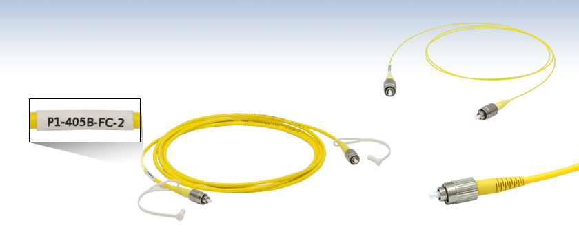
- SM Patch Cables for 320 to 2200 nm
- Terminated on Both Ends with High-Quality Ceramic FC/PC Connectors
- Low Back-Reflection at Fiber-to-Fiber Junctions
- Typical Return Loss: 50 dB (40 dB min)
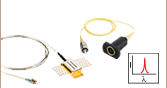
One End Labeled with Part
Number for Easy Identification
P1-405B-FC-2
405 - 532 nm Cable, Ø3 mm PVC Jacket,
2 m Long
FC/PC Connector
P1-780Y-FC-1
780 - 970 nm Cable,
Ø900 µm Hytrel® Jacket,
1 m Long


Please Wait
| Stock Single Mode Patch Cables Selection Guide | |
|---|---|
| Standard Cables | FC/PC to FC/PC |
| FC/APC to FC/APC | |
| Hybrid | |
| AR-Coated Patch Cables | |
| Thermally-Expanded-Core (TEC) Patch Cables | |
| HR-Coated Patch Cables | |
| Beamsplitter-Coated Patch Cables | |
| MIR Fluoride Fiber Patch Cables | |
特長
- 320 nm~2200 nmの透過帯域用SMパッチケーブル
- 両端のコネクタは2.0 mmのナローキーのFC/PCコネクタ
- 低い後方反射(高い反射減衰量): 50 dB (典型値)
- 標準品としてご提供
- ダストキャップが2個付属
当社では両端にFC/PCコネクタが付いたシングルモードパッチケーブルをご用意しております。全てのケーブルは当社施設の最先端の設備で製造されています。標準品としてはØ3 mm PVC被覆付き、またはØ900 µm Hytrel®*補強用チューブ付きがございます。Ø900 µmの被覆付きケーブルは径が小さいため、当社の手動型ファイバ偏光コントローラにご使用いただけます。
各パッチケーブルには、フェルール端を埃や他の異物から守るための保護キャップが2個付属しています。FC/PCコネクタ用の追加のプラスチック製保護キャップCAPFやネジ付き金属製ファイバーキャップCAPFMも別途販売しています。FC-FC、またFC-SMAコネクタの接続用のアダプタもご用意しています。アダプタを用いた接続では、後方反射が抑制され、2つのファイバコアが適切にアライメントされるので、損失も抑えられます。
また、当社ではARコーティング付きシングルモードパッチケーブルもご用意しており、ファイバから自由空間出力する用途で高い性能を発揮するために、ファイバ端に反射防止コーティングを施しています。お客様の要望に適した標準品のパッチケーブルが見つからない場合は、カスタムパッチケーブルもご用意しておりますのでお気軽にお問い合わせください。
*Hytrel®はDuPont Polymers社の登録商標です。
| Item # Prefix | P1-305A | P1-405Y | P1-405 | P1-405B | P1-460Y | P1-460B |
|---|---|---|---|---|---|---|
| Fiber | SM300 | S405-XP | SM400 | SM450 | ||
| Operating Wavelength | 320 - 430 nm | 400 - 680 nm | 405 - 532 nm | 488 - 633 nma | ||
| Cutoff Wavelength | ≤310 nm | 380 ± 20 nm | 305 - 400 nm | 350 - 470 nma | ||
| Mode Field Diameter (MFD)b | 2.0 - 2.4 µm @ 350 nm | 3.3 ± 0.5 µm @ 405 nm 4.6 ± 0.5 µm @ 630 nm | 2.5 - 3.4 µm @ 480 nm | 2.8 - 4.1 µm @ 488 nm | ||
| Cladding Diameter | 125 ± 1.0 µm | 125 ± 1.0 µm | 125 ± 1.0 µm | 125 ± 1.0 µm | ||
| Coating Diameter | 245 ± 15 µm | 245 ± 15 µm | 245 ± 15 µm | 245 ± 15 µm | ||
| Attenuation (Max)c | ≤70 dB/km @ 350 nm | ≤30.0 dB/km @ 630 nm ≤30.0 dB/km @ 488 nm | ≤50 dB/km @ 430 nm ≤30 dB/km @ 532 nm | ≤50 dB/km @ 488 nmd | ||
| NA | 0.12 - 0.14 | 0.12 | 0.12 - 0.14 | 0.10 - 0.14 | ||
| Typical Insertion Losse (Click to Enlarge) |  | |||||
| Protective Jacketing | Ø3 mm Yellow PVC Furcation Tubing | Ø900 µm Yellow Hytrel®f Tubing | Ø3 mm Yellow PVC Furcation Tubing | Ø3 mm Yellow PVC Furcation Tubing | Ø900 µm Yellow Hytrel®f Tubing | Ø3 mm Yellow PVC Furcation Tubing |
| Return Loss | 50 dB Typical (40 dB Min) | |||||
| Connectors | FC/PC Narrow Key (2.0 mm) on Both Ends | |||||
| Lengthg | 1 m (for Item #s Ending in -1) 2 m (for Item #s Ending in -2) 5 m (for Item #s Ending in -5) 10 m (for Item #s Ending in -10) | |||||
| Item # Prefix | P1-S630Y | P1-S630 | P1-630Y | P1-630A | P1-780Y | P1-780A | P1-830A | P1-980A |
|---|---|---|---|---|---|---|---|---|
| Fiber | S630-HP | SM600 | 780HP | SM800-5.6-125 | SM980-5.8-125 | |||
| Operating Wavelength | 630 - 860 nm | 633 - 780 nma | 780 - 970 nm | 830 - 980 nm | 980 - 1550 nma | |||
| Cutoff Wavelength | 590 ± 30 nm | 500 - 600 nm | 730 ± 30 nm | 660 - 800 nm | 870 - 970 nm | |||
| Mode Field Diameter (MFD)b | 4.2 ± 0.5 µm @ 630 nm | 3.6 - 5.3 µm @ 633 nm | 5.0 ± 0.5 µm @ 850 nm | 4.7 - 6.9 µm @ 830 nm | 5.3 - 6.4 µm @ 980 nm | |||
| Cladding Diameter | 125 ± 1.0 µm | 125 ± 1.0 µm | 125 ± 1 µm | 125 ± 1.0 µm | 125 ± 1.0 µm | |||
| Coating Diameter | 245 ± 15 µm | 245 ± 15 µm | 245 ± 15 µm | 245 ± 15 µm | 245 ± 15 µm | |||
| Attenuation (Max)c | ≤10 dB/km @ 630 nm | ≤15 dB/kmd | < 3.5 dB/km @ 780 nm | < 5 dB/kmd | ≤ 2.0 dB/kmd | |||
| NA | 0.12 | 0.10 - 0.14 | 0.13 | 0.10 - 0.14 | 0.13 - 0.15 | |||
| Typical Insertion Losse (Click to Enlarge) | | |||||||
| Protective Jacketing | Ø900 µm Yellow Hytrel®f Tubing | Ø3 mm Yellow PVC Furcation Tubing | Ø900 µm Yellow Hytrel®f Tubing | Ø3 mm Yellow PVC Furcation Tubing | Ø900 µm Yellow Hytrel® Tubing | Ø3 mm Yellow PVC Furcation Tubing | Ø3 mm Yellow PVC Furcation Tubing | |
| Return Loss | 50 dB Typical (40 dB Min) | |||||||
| Connectors | FC/PC Narrow Key (2.0 mm) on Both Ends | |||||||
| Lengthg | 1 m (for Item #s Ending in -1) 2 m (for Item #s Ending in -2) 5 m (for Item #s Ending in -5) 10 m (for Item #s Ending in -10) | |||||||
| Item # Prefix | P1-1064Y | P1-1064 | P1-SMF28Y | P1-SMF28E | P1-1550A | P1-1950 |
|---|---|---|---|---|---|---|
| Fiber | HI1060-J9 | SMF-28 Ultra | 1550BHP | SM1950 | ||
| Operating Wavelength | 980 - 1650 nm | 1260 - 1625 nm | 1460 - 1620 nm | 1850 - 2200 nm | ||
| Cutoff Wavelength | 920 ± 50 nm | < 1260 nm | 1400 ± 50 nm | 1720 ± 80 nm | ||
| Mode Field Diameter (MFD)a | 5.9 ± 0.3 µm @ 980 nm 6.2 ± 0.3 µm @ 1060 nm | 9.2 ± 0.4 µm @ 1310 nm 10.4 ± 0.5 µm @ 1550 nm | 9.5 ± 0.5 µm @ 1550 nm | 8.0 µm @ 1950 nm | ||
| Cladding Diameter | 125 ± 0.5 µm | 125 ± 0.7 µm | 125 ± 1 µm | 125 ± 1 µm | ||
| Coating Diameter | 245 ± 10 µm | 242 ± 5 µm | 245 ± 15 µm | 245 ± 10 µm | ||
| Attenuationb | 2.1 dB/km @ 980 nm (Max) 1.5 dB/km @1060 nm (Max) | ≤0.32 dB/km @ 1310 nm (Max) ≤0.18 dB/km @ 1550 nm (Max) | 0.5 dB/km @ 1550 nm (Max) | 5 dB/km @ 1900 nm (Typical) | ||
| NA | 0.14 | 0.14 | 0.13 | 0.20 | ||
| Typical Insertion Lossc (Click to Enlarge) | | |||||
| Protective Jacketing | Ø900 µm Yellow Hytrel®d Tubing | Ø3 mm Yellow PVC Furcation Tubing | Ø900 µm Yellow Hytrel® Tubing | Ø3 mm Yellow PVC Furcation Tubing | Ø3 mm Yellow PVC Furcation Tubing | |
| Return Loss | 50 dB Typical (40 dB Min) | |||||
| Connectors | FC/PC Narrow Key (2.0 mm) on Both Ends | |||||
| Lengthe | 1 m (for Item #s Ending in -1) 2 m (for Item #s Ending in -2) 5 m (for Item #s Ending in -5) 10 m (for Item #s Ending in -10) | |||||
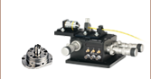
Click to Enlarge
Figure 56B ナローキー用アダプタとコネクタの接続
Click to Enlarge
Figure 56A ワイドキー用アダプタとコネクタの接続
FC/PCおよびFC/APCパッチケーブルのキーアライメント
FC/PCおよびFC/APCパッチケーブルには、接続部品のスロット部に接続できるアライメント用の2.0 mmのナローキーまたは2.2 mmのワイドキーが付いています。 これらのキーとスロットは接続したファイバーパッチケーブルのコアに正しくアライメントし、接続時の挿入損失を最小限に抑えるために重要です。
例えば、当社ではFC/PCならびにFC/APCパッチケーブル用のアダプタは、適切に使用されたとき接続損失が最小となるよう精密な仕様で設計・製造されています。パッチケーブルのアライメントキーがアダプタのナローキーまたはワイドキースロットに挿入されたとき、最適なアライメント状態となります。
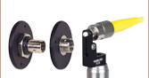
ワイドキー用スロット付きアダプタ
2.2 mmのワイドキー用スロット付きアダプタは、ワイドキーコネクタとナローキーコネクタのどちらにも対応しています。ただし、ナローキーコネクタをワイドキー用スロットに使用すると、コネクタはアダプタ内で僅かに回転します(Video 56C参照)。FC/PCコネクタ付きのパッチケーブルでは、この構成が可能ですが、FC/APCの用途において最適なアライメントを得るためにはナローキー用スロット付きアダプタのご使用をお勧めいたします。
ナローキー用スロット付きアダプタ
2.0 mmのナローキー用スロット付きアダプタは、角度付きナローキーFC/APCコネクタと接続した時に適切なアライメントができます(Video 56D参照)。したがって、2.2 mmワイドキー付きのコネクタには対応していません。なお、当社の全てのFC/PCおよびFC/APCパッチケーブルはナローキーコネクタをご使用いただけます。
ナローキー用スロット付きアダプタに挿入されたナローキーコネクタは回転しません。したがって、ナローキー付きのFC/PCまたはFC/APCコネクタとのご使用が適しています。
ナローキーコネクタをワイドキー用スロット付きアダプタに挿入すると、隙間ができてコネクタが回転してしまいます。ナローキーFC/PCコネクタはお使いいただけますが、ナローキーFC/APCコネクタをお使いになると著しい結合損失につながります。
| Quick Links |
|---|
| Damage at the Air / Glass Interface |
| Intrinsic Damage Threshold |
| Preparation and Handling of Optical Fibers |
レーザによる石英ファイバの損傷
このチュートリアルではコネクタ無し(素線)ファイバ、コネクタ付きファイバ、およびレーザ光源に接続するその他のファイバ部品に関連する損傷メカニズムを詳しく説明しています。そのメカニズムには、空気/ガラス界面(自由空間結合時、またはコネクタ使用時)ならびにファイバ内における損傷が含まれます。ファイバ素線、パッチケーブル、または溶融型カプラなどのファイバ部品の場合、損傷につながる複数の可能性(例:コネクタ、ファイバ端面、機器そのもの)があります。ファイバが対処できる最大パワーは、常にそれらの損傷メカニズムの中の最小の限界値以下に制限されます。
損傷閾値はスケーリング則や一般的なルールを用いて推定することはできますが、ファイバの損傷閾値の絶対値は利用方法やユーザ定義に大きく依存します。このガイドは、損傷リスクを最小に抑える安全なパワーレベルを推定するためにご利用いただくことができます。適切な準備と取扱い方法に関するガイドラインにすべて従えば、ファイバ部品は規定された最大パワーレベルで使うことができます。最大パワーの値が規定されていない場合は、部品を安全に使用するために下表の「実用的な安全レベル」の範囲に留めてご使用ください。 パワー処理能力を低下させ、ファイバ部品に損傷を与える可能性がある要因は、ファイバ結合時のミスアライメント、ファイバ端面の汚れ、あるいはファイバそのものの欠陥などですが、これらに限られるわけではありません。特定の用途におけるファイバのパワー処理能力に関するお問い合わせは当社までご連絡ください。
空気/ガラス界面における損傷
空気/ガラス界面ではいくつかの損傷メカニズムが存在する可能性があります。自由空間結合の時、またはコネクタで2本のファイバを結合した時、光はこの界面に入射します。高強度の光は端面を損傷し、ファイバのパワー処理能力の低下や恒久的な損傷につながる場合があります。コネクタ付きのファイバで、コネクタがエポキシ接着剤でファイバに固定されている場合、高強度の光によって発生した熱により接着剤が焼けて、ファイバ端面に残留物が残る可能性があります。
| Table 36C Estimated Optical Power Densities on Air / Glass Interfacea | ||
|---|---|---|
| Type | Theoretical Damage Thresholdb | Practical Safe Levelc |
| CW (Average Power) | ~1 MW/cm2 | ~250 kW/cm2 |
| 10 ns Pulsed (Peak Power) | ~5 GW/cm2 | ~1 GW/cm2 |
ファイバ素線端面での損傷メカニズム
ファイバ端面での損傷メカニズムはバルクの光学素子の場合と同様なモデル化ができ、UV溶融石英(UVFS)基板の標準的な損傷閾値を石英ファイバに当てはめることができます。しかしバルクの光学素子とは異なり、光ファイバの空気/ガラス界面においてこの問題に関係する表面積やビーム径は非常に小さく、特にシングルモードファイバの場合はそれが顕著です。 パワー密度が与えられたとき、ファイバに入射するパワーは、小さいビーム径に対しては小さくする必要があります。
右の表では光パワー密度に対する2つの閾値が記載されています。理論的な損傷閾値と「実用的な安全レベル」です。一般に、理論的損傷閾値は、ファイバ端面の状態も結合状態も非常に良いという条件で、損傷のリスク無しにファイバの端面に入射できる最大パワー密度の推定値を表しています。「実用的な安全レベル」のパワー密度は、ファイバ損傷のリスクが極めて小さくなる値を示しています。ファイバまたはファイバ部品をこの実用的な安全レベルを超えて使用することは可能ですが、その時は取扱い上の注意事項を適切に守り、使用前にローパワーで性能をテストする必要があります。
シングルモードの実効面積の計算
シングルモードファイバの実効面積は、モードフィールド径(MFD)、すなわちファイバ内の光が伝搬する部分の断面積によって定義されます。この面積にはファイバのコアとクラッドの一部が含まれます。シングルモードファイバとの結合効率を良くするためには、入射ビーム径をファイバのモードフィールド径に合致させなければなりません。
例として、シングルモードファイバSM400を400 nmで使用した時のモードフィールド径(MFD)は約Ø3 µmで、SMF-28 Ultraを1550 nmで使用したときのモードフィールド径(MFD)はØ10.5 µmです。これらのファイバの実効面積は下記の通り計算します。
SM400 Fiber: Area = Pi x (MFD/2)2 = Pi x (1.5 µm)2 = 7.07 µm2 = 7.07 x 10⁻⁸ cm2
SMF-28 Ultra Fiber: Area = Pi x (MFD/2)2 = Pi x (5.25 µm)2 = 86.6 µm2 = 8.66 x 10⁻⁷ cm2
ファイバ端面が対応できるパワーを推定するには、パワー密度に実効面積を乗じます。なおこの計算は均一な強度プロファイルを想定しています。しかしほとんどのレーザービームでは、シングルモード内でガウス分布を示すため、ビームの端よりも中央のパワー密度が高くなります。よって、これらの計算は損傷閾値または実用的安全レベルに対応するパワーとは若干異なることを考慮する必要があります。連続光源を想定して上記のパワー密度の推定値を使用すると、それぞれのパワーは下記のように求められます。
SM400 Fiber: 7.07 x 10⁻⁸ cm2 x 1 MW/cm2 = 7.1 x 10⁻⁸ MW = 71 mW (理論的損傷閾値)
7.07 x 10⁻⁸ cm2 x 250 kW/cm2 = 1.8 x 10⁻⁵ kW = 18 mW (実用的な安全レベル)
SMF-28 Ultra Fiber: 8.66 x 10⁻⁷ cm2 x 1 MW/cm2 = 8.7 x 10⁻⁷ MW = 870 mW (理論的損傷閾値)
8.66 x 10⁻⁷ cm2 x 250 kW/cm2 = 2.1 x 10⁻⁴ kW = 210 mW (実用的な安全レベル)
マルチモードの実効面積
マルチモードファイバの実効面積は、そのコア径によって定義されますが、一般にシングルモードファイバのMFDよりもはるかに大きくなります。当社では最適な結合を得るためにコア径のおよそ70~80%にビームを集光することをお勧めしています。マルチモードファイバでは実効面積が大きくなるほどファイバ端面でのパワー密度は下がるので、より大きな光パワー(通常キロワットオーダ)を入射しても損傷は生じません。
フェルール・コネクタ付きファイバに関する損傷メカニズム
 Click to Enlarge
Figure 36D コネクタ付きシングルモード石英ファイバに入力可能なパワー処理限界値(概算)を示したグラフ。各線はそれぞれの損傷メカニズムに応じたパワーレベルの推定値を示しています。入力可能な最大パワーは、損傷メカニズムごとに制限されるパワーのうちの一番小さな値(実線で表示)によって制限されます。
コネクタ付きファイバのパワー処理能力に関しては、ほかにも考慮すべき点があります。ファイバは通常、エポキシ接着剤でセラミック製またはスチール製のフェルールに取り付けられています。光がコネクタを通してファイバに結合されると、コアに入射せずにファイバを伝搬する光は散乱されてファイバの外層からフェルール内へ、さらにフェルール内でファイバを保持する接着剤へと伝搬します。光の強度が大きいとエポキシ接着剤が焼け、それが蒸発して残留物がコネクタ端面に付着します。これによりファイバ端面に局所的に光を吸収する部分ができ、それに伴って結合効率が減少して散乱が増加するため、さらなる損傷の原因となります。
エポキシ接着剤に関連する損傷は、いくつかの理由により波長に依存します。一般に、光の散乱は長波長よりも短波長で大きくなります。短波長用のMFDの小さなシングルモードファイバへの結合時には、ミスアライメントに伴ってより多くの散乱光が発生する可能性があります。
エポキシ樹脂が焼損するリスクを最小に抑えるために、ファイバ端面付近のファイバとフェルール間にエポキシ接着剤の無いエアギャップを有するファイバーコネクタを構築することができます。当社の高出力用マルチモードファイバーパッチケーブルでは、このような設計のコネクタを使用しております。
複数の損傷メカニズムがあるときのパワー処理限界値を求める方法
ファイバーケーブルまたはファイバ部品において複数の損傷要因がある場合(例:ファイバーパッチケーブル)、入力可能なパワーの最大値は必ずファイバ部品構成要素ごとの損傷閾値の中の一番小さな値により決まります。この値が一般的にはパッチケーブルの端面に入射可能な最大のパワーを表します(出力パワーではありません)。
Figure 36Dでは、シングルモードパッチケーブルにおけるファイバ端面での損傷とコネクタでの損傷に伴うパワー処理限界の推定値を例示しています。 ある波長におけるコネクタ付きファイバの総合的なパワー処理限界値は、その波長に対する2つの制限値の小さい方の値(実線)によって制限されます。488 nm付近で使用しているシングルモードファイバは主にファイバ端面の損傷(青い実線)によって制限されますが、1550 nmで使用しているファイバはコネクタの損傷(赤い実線)によって制限されます。
マルチモードファイバの実効面積はコア径で定義され、シングルモードファイバの実効面積より大きくなります。その結果、ファイバ端面のパワー密度が小さくなり、大きな光パワー(通常キロワットオーダ)を入射してもファイバに損傷は生じません(グラフには表示されていません)。しかし、フェルール・コネクタの損傷による限界値は変わらないため、マルチモードファイバが処理できる最大パワーはフェルールとコネクタによって制限されることになります。
上記の値は、取り扱いやアライメントが適切で、それらによる損傷が生じない場合のパワーレベルです。また、ファイバはここに記載されているパワーレベルを超えて使用されることもあります。しかし、そのような使い方をする場合は一般に専門的な知識が必要で、まずローパワーでテストして損傷のリスクを最小限に抑える必要があります。その場合においても、ハイパワーで使用するファイバ部品は消耗品と捉えた方が良いでしょう。
ファイバ内の損傷閾値
空気/ガラス界面で発生する損傷に加え、ファイバのパワー処理能力はファイバ内で発生する損傷メカニズムによっても制限されます。この制限はファイバ自体が本質的に有するもので、すべてのファイバ部品に適用されます。ファイバ内の損傷は、曲げ損失による損傷とフォトダークニングによる損傷の2つに分類されます。
曲げ損失
ファイバが鋭く曲げられると、コア内を伝搬する光がコア/クラッド界面において反射する際に、その反射角が全反射臨界角よりも大きくなります。曲げ損失は、このように内部全反射ができなくなることにより生じる損失です。このような状況下では、光はファイバから局所的に漏れだします。漏れる光のパワー密度は一般に大きく、ファイバのコーティングや補強チューブが焼損する可能性があります。
特殊ファイバに分類されるダブルクラッドファイバは、コアに加えてファイバのクラッド(2層目)も導波路として機能するため、曲げ損失による損傷のリスクが抑えられます。クラッドと被覆の界面の臨界角をコアとクラッドの界面の臨界角より大きくすることで、コアから漏れた光はクラッド内に緩く閉じ込められます。その後、光はセンチメートルからメートルオーダーの距離に渡って漏れ出しますが、局所的ではないため損傷リスクは最小に留められます。当社ではメガワットレベルの大きなパワーにも対応するNA 0.22のダブルクラッドマルチモードファイバを製造、販売しております。
フォトダークニング
もう1つのファイバ内の損傷メカニズムとして、特にコアにゲルマニウムが添加されたファイバをUVや短波長の可視光で使用した時に起こるフォトダークニングまたはソラリゼーションがあります。これらの波長で使用されたファイバは時間の経過とともに減衰量が増加します。 フォトダークニングが発生するメカニズムはほとんど分かっていませんが、その現象を緩和するファイバはいくつか開発されています。例えば、水酸イオン(OH)が非常に低いファイバはフォトダークニングに耐性があることが分かっています。またフッ化物などのほかの添加物もフォトダークニングを低減させる効果があります。
しかし、上記の対応をとったとしても、UV光や短波長に使用したファイバはいずれフォトダークニングが生じます。よってこれらの波長で使用するファイバは消耗品としてお考えください。
光ファイバの準備ならびに取扱い方法
一般的なクリーニングならびに操作ガイドライン
この一般的なクリーニングならびに操作ガイドラインはすべてのファイバ製品向けにお勧めしております。さらに付属資料やマニュアルに記載された個々の製品に特化したガイドラインも遵守してください。損傷閾値の計算は、すべてのクリーニングおよび取扱い手順に適切に従ったときにのみ適用することができます。
(コネクタ付き、またはファイバ素線に関わらず)ファイバを設置または組み込む前に、すべての光源はOFFにしてください。これにより、損傷の可能性のあるコネクタまたはファイバの脆弱な部分に集光されたビームが入射しないようにすることができます。
ファイバやコネクタ端面の品質がファイバのパワー処理能力に直結します。ファイバを光学系に接続する前に必ずファイバ端を点検してください。端面はきれいで、入射光の散乱を招く汚れや汚染物質があってはなりません。ファイバ素線は使用前にクリーブし、クリーブの状態が良好であることを確認するためにファイバ端面の点検をしてください。
ファイバを光学系に融着接続する場合、ハイパワーで使用する前にまずローパワーで融着接続の状態が良いことを確認してください。融着接続の品質が良くないと接続面での散乱が増え、ファイバ損傷の原因となる場合があります。
システムのアライメントや光結合の最適化などの作業はローパワーで行ってください。これによりファイバの(コア以外の)他の部分の露光が最小に抑えられます。ハイパワーのビームがクラッド、被覆またはコネクタに集光された場合、散乱光による損傷が発生する可能性があります。
ハイパワーでファイバを使用するための要点
光ファイバやファイバ部品は一般には安全なパワー限界値内で使用する必要がありますが、アライメントや端面のクリーニングがとても良い理想的な条件下では、ファイバ部品のパワー限界値を上げることができる場合があります。入力または出力パワーを増加させる前に、システム内のファイバ部品の性能と安定性を確認し、またすべての安全ならびに操作に関する指示に従わなければなりません。下記はファイバ内またはファイバ部品内の光パワーをの増大させること加を検討していするときに役立つご提案です。
ファイバースプライサを使用してファイバ部品をシステムに融着接続すると、空気/ファイバ界面での損傷の可能性を最小化できます。品質の高い融着接続が実現されるよう、すべて適切なガイドラインに則って実施する必要があります。融着接続の状態が悪いと、散乱や融着接続面での局所的な加熱などが発生し、ファイバを損傷する可能性があります。
ファイバまたはファイバ部品の接続後、ローパワーでシステムのテストやアライメントを実施してください。システムパワーを必要な出力パワーまで徐々に上昇させ、その間、定期的にすべての部品が適切にアライメントされ、結合効率が入力パワーによって変動していないことを確認します。
ファイバを鋭く曲げると曲げ損失が発生し、ファイバのストレスを受けた部分から光が漏れる可能性があります。ハイパワーで使用している時は、大量の光が小さな局所領域(歪みのある領域)から流出すると局所的に加熱され、ファイバが損傷する可能性があります。使用中はファイバの曲げが生じないよう配慮し、曲げ損失を最小限に抑えてください。
また、用途に適したファイバを選ぶことも損傷防止に役立ちます。例えば、ラージモードエリアファイバは、標準的なシングルモードファイバをハイパワー光用として用いる場合の良い代替品となります。優れたビーム品質を有しながらMFDも大きいため、空気/ファイバ界面でのパワー密度は小さくなります。
ステップインデックスシングルモード石英ファイバは、一般にUV光やピークパワーの大きなパルス光には使用しませんが、これはその用途に伴う空間パワー密度が大きいためです。

Insights:光ファイバ
こちらのページでは下記について説明しています。
- NAはファイバの受光角を表す指標となり得るか?
- MFDがシングルモードファイバにおいて重要な結合パラメータである理由とは?
- NAによりシングルモードファイバからのビーム広がり角がわかるか?
このほかにも実験・実習や機器に関するヒントをまとめて掲載しています。こちらからご覧ください。
NAはファイバの受光角を表す指標となり得るか?
Click to Enlarge
図1:入射角が≤θmaxの光線は、マルチモードファイバのコア内に閉じ込められます。これらの光線がコアとクラッドの界面で全反射するからです。
Click to Enlarge
図2:コアとクラッドの境界での光の作用は、コアとクラッドの屈折率に依存し、端面に入射された光がコア内に結合するかを決定します。NAは幾何学的計算と、図の上にある2つの式を用いて求められます。
開口数(NA) は、ほとんどのマルチモードファイバにおいて図1のように最大の受光角を表します。この関係性はシングルモードファイバにおいては適用することができません。
開口数(NA)と受光角
入射光の光線モデルで、開口数と最大受光角(θmax )の関係性を表します。最大受光角は、軸外の光源からの光を集光できるファイバの能力を示します。図1の上にある計算式は、異なる光源からの光線がファイバのコアに結合できるかを判断するために使用できます。
入射角が≤θmax aの光線は、ファイバのコアとクラッド間の境界において全内部反射(TIR)します。これらの光線はファイバ内を伝搬していくので、コア内に閉じ込められたままとなります。
入射角がθmax よりも大きい光線については、コアとクラッド間の境界で屈折し、部分的に透過するので、結果的に減衰していきます。
関係性は幾何学によって定義されます
NA、θmax 、コアとクラッドの屈折率ncore とnclad の関係性は、図2で表すことができます。この図では、コアとクラッド間の境界で全反射が生じる最も極端な条件を示しています。
図2の上にある計算式は、スネルの法則によるもので、境界の両側における光線の挙動を示します。なお、式の簡易化でsin(90°) = 1が使用されています。θmax の値を制限するのはコアとクラッドの屈折率だけです。
入射角とファイバのモード
入射角が≤θmax のとき、入射光はマルチモードファイバの導波モードのどれか1つに結合されます。一般的に言えば、入射角が小さければ小さいほど、励起されるファイバのモード次数も小さくなります。次数が小さいモードは、強度をコアの中心近くに集中させます。次数が最も小さいモードは、端面に垂直に入射された光によって励起されます。
シングルモードファイバではご利用いただけません
シングルモードファイバの場合、図2のような光線モデルは使用できず、計算した開口数(受光角)は、最大の入射角度に等しくはなく、またファイバの集光能力を表すものではありません。
シングルモードファイバの導波モードは1つ、次数が最も小さいモードで、入射角が0°の光によって励起されます。しかし、NAを計算すると、その値は0ではありません。光線モデルでは、シングルモードファイバから放射、または結合された光線の広がり角を正確に予測することもできません。ビームの広がりは回折効果によって起こりますが、光線モデルにおいては考慮されていません。しかし、波動光学モデルによれば説明可能です。ガウシアンビームの伝搬モデルを使用すれば高確度でビームの広がり角を求めることができます。
最終更新日:2020年1月20日
MFDがシングルモードファイバにおいて重要な結合パラメータである理由とは?
Click to Enlarge
図3:最大の結合効率でシングルモードファイバに結合するためには、光が軸上のガウシアンビームで、ウェスト位置がファイバの端面にあり、ウェスト径がMFDと等しくなる必要があります。ファイバの出射光もこれらの特性によりガウス分布に近い形状となります。シングルモードファイバにおいて、開口数(NA)の使用した光線モデルは、結合状態を決定するには不適切です。ここでは半径( ρ )におけるモード強度(I )プロファイルが示されています。
光はシングルモードファイバを伝搬していくと、そのビーム断面の強度分布はガウス分布に似た形状となります。モードフィールド径(MFD)はこの強度プロファイルの幅を表します。入射ビームがこの強度プロファイルに合致すればするほど、より効率よく多くの光がファイバに結合します。入射されるガウシアンビームのビームウェストがMFDと等しいと、とりわけ高い結合効率が得られます。
ガウシアンビームの伝搬モデルにおいてMFDをビームウェストにすることで、確度の高い入射ビームパラメータと出射ビームの広がり角を得ることができます。
結合条件の決定
光ファイバの利点は、ファイバの導波モードによって伝播される光が放射線状には広がらず、最小限の減衰で伝搬していくことです。光をファイバの導波モードに結合するには、入射ビームと導波モードの特性を一致させる必要があります。導波モードに結合しない光はファイバの外に放射されます。光がファイバから漏れ出したと言えるのです。
シングルモードファイバの導波モードは1つであり、波動光学解析によってモードをベッセル関数で表すことができます。ガウス関数とベッセル関数の振幅プロファイルは、非常によく似ており(Kowalevicz氏。下記参考文献参照)、代わりにガウス関数を使用すると正確な結果をもたらしながら、ファイバのモードのモデリングが簡易化されるので便利です。
プロファイルは、径方向距離(I )プロファイルは、径方向距離( ρ )のガウス関数にほぼ一致します。MFDは、ファイバ長に沿って一定で、e-2とピーク強度の積に等しい強度の幅です。モードフィールド径(MFD)内は、ビームパワーの約86%が含まれます。
次数が最も小さい横モードだけが放射されるレーザ出力光はガウシアンビームとなるため、このレーザ光はシングルモードファイバに良い結合効率で結合できます。
シングルモードファイバへの光の結合
シングルモードファイバのコアに効率よく光を結合するには、入射するガウシアンビームのウェストをファイバの端面に合せてください。ビームウェストの強度プロファイルは、モードの断面の強度の特性と重複し、合致しなければなりません。入射ビームに必要なパラメータは、ガウシアンビームの伝搬モデルとファイバのMFDから求めることができます。
結合効率が小さくなるのは、ビームウェスト径とMFDが一致しない、端面のモーダルスポットによりビームの断面のプロファイルが歪んだり、中心がずれている、光がファイバの軸に沿って誘導されていない場合に起こります。
参考文献
Kowalevicz A and Bucholtz F, "Beam Divergence from an SMF-28 Optical Fiber (NRL/MR/5650--06-8996)." Naval Research Laboratory, 2006.
最終更新日:2020年2月28日
NAによりシングルモードファイバからのビーム広がり角がわかるか?
開口数(NA)を使用してシングルモードファイバから出射される、あるいはシングルモードファイバに結合する光円錐を概算する場合、大きな誤差が生じる場合があります。広がり角はガウシアンビーム伝搬モデルを使用した方がより良い概算値が得られます。このモデルにより、広がり角を算出し、用途に適したビームスポットサイズを得ることができます。
シングルモードファイバにおけるモードフィールド径(MFD)内は、ビームパワーの約86%が含まれるため、MFDによりスポットサイズを決めることは、シングルモードファイバから光をコリメートしたり、光を集光する際の適切な定義であるとされています。一次近似でファーフィールドで測定されたとき、
 , , | (1) |
は、広がり角または受光角(θSM )(単位:ラジアン)です。これは1/2ビーム角で、波長 )
)
| Rayleigh Range: | ||
 | ||
| Beam Radius at Distance z: | ||
 | ||
図4:青い線は、シングルモードファイバからの出射光の広がり角(θSM )をNAを用いて計算した結果を示しています。赤い線は、ガウシアンビーム伝搬モデルを使用して計算されており、これにより、ビームスポット径の大きな誤差を回避することができます。 こちらのグラフではSM980-5.8-125からのビームをモデル化しています。NAは0.13、MFDは6.4 µmの値を使用しています。動作波長は980 nm、レイリー範囲は32.8 µmでした。 | ||
ガウシアンビームによるアプローチ
シングルモードファイバの端面から出射される光は円錐状に広がりますが、この光はファイバ軸から様々な角度で出力する複数の光線と同様の振る舞いにはなりません。
この光はガウシアンビームに似ており、モデル化ができます。放射光がガウシアンビームと同様に伝搬するのは、光の導波モードがガウス分布に近似しているからです。
ガウシアンビームの広がり角は、光線として作用する光を想定して計算された広がり角度とは実質的に異なります。光線モデルを使用した場合、広がり角は sin-1(NA)となります。しかし、NAと広がり角の関係性は高次マルチモードファイバのみ有効です。
図4では、NAを使用して広がり角を計算すると大きな違いが生じる可能性を示しています。 ガウシアンビームでは、広がり角はビームパワーの86%を含む領域とされており、この領域の境界円における強度は、ピーク強度の1/e2となっています。
図4の右の式は、シングルモードファイバ端面から出射されるビームの広がり角を正確にモデル化するガウシアンビームの式です。計算に使用するファイバのMFD、NAならびに動作波長を含む値はグラフ下に記載されています。ビーム発散角は、 1/e2半径によって定義されたビームサイズの変化により算出されています。ビームサイズは、z < zRの距離においては非線形で、ファーフィールド(z >> zR)においてはほぼ線形に変化します。
グラフに記載されている角度は各曲線の傾斜から計算されました。式(1)で求めたファーフィールドの概算が使用された場合、広がり角は0.098ラジアン(5.61°)です。
参考文献
Kowalevicz A and Bucholtz F, "Beam Divergence from an SMF-28 Optical Fiber (NRL/MR/5650--06-8996)." Naval Research Laboratory, 2006.
最終更新日:2020年2月28日
Content improved by our readers!
| Posted Comments: | |
Artur Matoso
(posted 2025-04-03 06:54:51.953) My name is Artur Matoso, currently I held a posdoc position in the Federal univesity of Minas Gerais. As requested in you website, I would like to ask for the refractive index value of the 780HP fiber. For our puposes, we need to know it with the largest number of decimal places as possible.
Thanks in advance,
Best regards Everett Lipman
(posted 2025-03-17 02:29:21.917) It's really annoying not to have the specifications on the product page. jdelia
(posted 2025-03-17 12:31:08.0) Thank you for contacting Thorlabs. The specs for the products can be found by simply navigating to the "Specs" tab or by scrolling down the page and glancing at the tables containing specifications for the listed products. I have reached out to you directly to clarify your inquiry. Jaya Sagar
(posted 2024-02-15 16:00:30.997) Hi, Can you make a SMF, FC/PC, 900um coating, 780-970nm, patch cable of a custom length - 219mm for us ? jdelia
(posted 2024-02-15 01:59:54.0) Thank you for contacting Thorlabs. I have reached out to you directly to discuss the feasibility of this customized item request. Alois Mair
(posted 2023-11-20 15:06:30.78) What ist the operation or cutoff wavelength? We still have and use them in our labs. jdelia
(posted 2023-11-22 11:51:31.0) Thank you for contacting Thorlabs. The cable you are referring to is the P1-3224-FC-2, which was made out of our obsolete FS-SN-3224 fiber. You can find the catalog presentation, which includes the specs of the fiber, in the "Catalog Presentation" from the following link: https://www.thorlabs.com/thorproduct.cfm?partnumber=FS-SN-3224 Jisoo Kyoung
(posted 2023-06-27 12:49:02.677) Dear Thorlabs,
Hello, I am interested in your fiber: P1-630A-FC-1 - Single Mode Patch Cable, 633 - 780 nm, FC/PC, Ø3 mm Jacket, 1 m Long.
I would like to use it to deliver my femtosecond laser (center wavelength: 780 nm, pulse width ~100 fs) to a semiconductor device.
In our case, the dispersion compensation is important.
Therefore, I am wondering about the group dispersion delay of your fiber.
Could you tell me about the GDD value of your product?
Thanks. jpolaris
(posted 2023-06-27 08:35:23.0) Thank you for contacting Thorlabs. We do not have hard data on dispersion for P1-630A-FC-1 at this moment. P1-630A-FC-1 uses SM600 fiber. In general, the trend for material dispersion is that it would be larger for longer wavelengths. For SM600 at 600 nm, the group velocity dispersion (GVD), which is the group delay dispersion (GDD) per unit length, is estimated to be within -300 ps/nm*km to -400 ps/nm*km. At 780 nm, we expect GVD to be closer to -150 ps/nm*km. Felix Koch
(posted 2023-02-03 15:07:14.817) Hello,
we would like to use the P1-305A-FC with a 320 nm laser in single-mode operation. Can you recommend an FC/PC fiber collimator for coupling in the d~1 mm collimated beam? It seems like the typical solutions from thorlabs (fixed focus asphere like F671FC-405, fixed focus triplets) use glasses with dramatically reduced transmission @ 320 nm.
There are also the OAP mirror collimators which are quite costly (e.g. RC02FC-F01). Are there any recommended alternatives? Is the transmission of the fiber acceptable at 320 nm?
Best regards
Felix jgreschler
(posted 2023-02-03 11:05:03.0) Thank you for contacting Thorlabs. The correct choice of coupling lens is dependent on the application, I have reached out to you directly to discuss your specific requirements. Tommaso Marcato
(posted 2022-08-03 08:03:04.773) Dear Mr./Ms., Is it possible to know the MFD of the P1-460Y-FC fiber at 532 nm? I'd like to be able to estimate more exactly the focal length required for the fiber collimator but I can only find the specs at 488 nm which have a pretty big range. Thanks! jgreschler
(posted 2022-08-03 04:54:26.0) Thank you for reaching out to Thorlabs. Additional specifications and parameters can be requested by emailing techsupport@thorlabs.com. I have contacted you directly to discuss this application further. Viktor Dubec
(posted 2021-10-15 13:08:33.473) Hello, I bought the P1-305A-FC recently. I tested it with my TEM00 405nm laser. I got MULTIMODE output! Some explanation please? Do I do something wrong? I do not think that the light is transferred through the cladding, because the cladding produces visible ring if I misalign the system. Thank you! azandani
(posted 2021-10-20 05:29:01.0) Hello Viktor, thank you for contacting Thorlabs. We will reach out to you to troubleshoot directly. NIKHIL SEN
(posted 2020-11-24 15:32:06.74) We are using this fiber for a specific application in our experimental set up for which we need to know the group velocity dispersion of this fiber. This data is not provided in specs list, can you please provide us with GVD data(/graph)? YLohia
(posted 2020-12-29 03:22:22.0) Hello Nikhil, thank you for contacting Thorlabs. What's the part number of the fiber that you're specifically referring to? And at what wavelength are you planning on operating at? I had reached out to you directly at the time of your original post. If you're still interested in this information, please contact us at techsupport@thorlabs.com. ALEXEY KALMYKOV
(posted 2020-02-18 02:50:26.02) Dear friend!
I have a question about fibers designation. Tell me please what does the number after wavelength mean? e.g. P1-780A, what does "A" mean? llamb
(posted 2020-02-18 02:18:19.0) Thank you for your feedback. The "A" character after the wavelength in our patch cable part numbers refers to patch cables with Ø3 mm tubing, though this is not fully comprehensive of our Ø3 mm tubing options. By comparison, all cables with the "Y" character after the wavelength will have our FT900Y Ø900 µm yellow tubing. ynsnkim
(posted 2018-06-28 17:16:19.09) Hello,
Is there a way to approximate MFD for different wavelengths? In the overview MFD = 5.0 ± 0.5 μm @ 850 nm.
But I would like to know MFD specifically at 795 mm.
Thanks,
Youngshin YLohia
(posted 2018-07-03 10:26:42.0) It is possible to calculate the MFD for different wavelengths using Marcuse's equation. For this fiber being operated at 795nm, the equation yielded a Mode Field Diameter of ~5.34um. bbramman
(posted 2017-10-24 12:59:49.33) Hello,
Would the SM450 fiber optics work well for carrying both 493nm and 650nm laser beams?
Thanks,
Brendan nbayconich
(posted 2017-11-27 03:13:37.0) Thank you for contacting Thorlabs. SM450 can be used at wavelengths up to 650nm however the bend loss will be high at about 35 dB per loop for a 30mm bend radius. The dispersion at 650nm is about 57ps^2/km.
I will contact you directly with more information about the attenuation. William.C.Smith
(posted 2017-01-26 08:43:11.483) looking for fiber patch cables that can handle -57 to 57 C. Ones I have tried have lost the test signal at cold, suspect tubing pinching fiber. Using bare fiber now but it is very hard to work with this way.
1550nm, FC/PC connectors both ends, single mode, 2m to 2.5m, pbui
(posted 2017-01-30 04:09:35.0) Thank you for your feedback. We will contact you directly to discuss potential solutions for your application. nhatquang85
(posted 2016-11-22 00:54:05.057) How much power can the P1-460B-FC-2 and P1-630A-FC-2 fibers tolerate when coupling? We burnt the edge of the fiber (three of P1-460B-FC-2 and one of P1-630A-FC) when using only 01 mW of input light. We are using 532 nm pulsed laser at 6 ns pulse width. The coupling efficiency was only 30% when the edge of the fibers was burnt. tfrisch
(posted 2016-11-22 07:53:48.0) Hello, thank you for contacting Thorlabs. Typical power limits for a connectorized fiber are about 300mW of CW power, but this is limited by the adhesive that holds the fiber in the connector, and it assumes that the coupling efficiency has already been maximized. If the coupling efficiency is low, then the lost light can be absorbed by the adhesive. Also keep in mind that the damage threshold is greatly reduced if the face of the fiber is scratched or dirty, and fibers should be cleaned before they are added to a system. I will contact you directly. user
(posted 2016-08-01 10:40:07.45) Hi, I'd like to know the MFD for S405-HP @ 514.5 nm & 532 nm. Any available informaion? k.bong
(posted 2016-06-21 05:17:18.983) Whats the group delay dispersion of the fiber at 780nm? besembeson
(posted 2016-06-22 09:55:44.0) Response from Bweh at Thorlabs USA: I will contact you with an estimate. user
(posted 2014-10-06 09:58:41.32) This is your web page on pigtai LD :
http://www.thorlabs.co.jp/newgrouppage9.cfm?objectgroup_id=1489
It looks that your fiber used in pigtailed LD handles much mor power than the guideline of DT. How do the fiber in your pigtail LD manage such the high power ? jlow
(posted 2014-10-08 04:14:48.0) Response from Jeremy at Thorlabs: Typically the limitation for power handling in connectorized fiber depends on the coupling efficiency and cleanliness of the fiber end face. If the coupling efficiency is very high and the fiber end face is clean, then one could couple much more power into the fiber than the general safe guideline we provided. ecke
(posted 2014-01-21 15:47:46.353) What is the electrical high-voltage strength of these fiber cables?
Please specify applicable electrical voltage per cm or per m cable length. jlow
(posted 2014-01-27 08:15:30.0) Response from Jeremy at Thorlabs: All the materials inside the patch cable (fiber, PVC jacket, polypropylene inner tube, Kevlar threads) have higher breakdown voltage than air. Therefore breakdown will occur in air before it will occur in the fiber optic cable. user
(posted 2013-08-13 15:59:13.177) Why do you sell 1550BHP? What would be advantage for the more expensive fiber patch? jlow
(posted 2013-08-13 14:33:00.0) Response from Jeremy at Thorlabs: The 1550BHP was initially offered as a lower bend-loss alternative to SMF-28e+ fiber. However, with the addition of the CCC1310-J9 fiber at a later date, the clear advantage has vanished. There are some customers who have designed systems around this specific fiber and we have decided to continue carrying the 1550BHP fiber for ease of procurement for our customers. ecerda
(posted 2013-08-09 11:03:27.573) Hi. I would like to send a 6 ps @810nm pulse through a very long fiber (25m). I wonder how much dispersion I will get and how much power I can couple in a SM fiber. Thank you. cdaly
(posted 2013-08-15 16:12:00.0) Response from Chris at Thorlabs: Thank you for using out feedback tool. Dispersion is going to be dependent on the specific fiber which you are using. Not all single mode fiber is going to have the same value for this. I will contact you directly to discuss this with you. hambitza
(posted 2013-07-02 02:43:11.913) Could you specify the maximum power which e.g. the
P1-980A-FC-2 can support? I am using 1083 nm, cw. I already read in the comments below that one should use low powers for the initial coupling to not burn the cladding, but once it is well coupled in, how much power can be used? pbui
(posted 2013-07-08 17:36:00.0) Response from Phong at Thorlabs: Thank you for your post. Once the laser is well coupled into the fiber, we typically provide safe guideline values of 300 mW for visible wavelengths. However, due to the wavelength dependency, at 980 nm, you may be able to couple as much as 3 W with 90% chance of success. If you increase the power to 5 W, you may get 50% success. For 10 W, you may see only 10% success. Due to misalignment, hot spots can form, resulting in damage to the connector's epoxy. lauri.hallman
(posted 2013-05-17 10:50:48.59) Hi,
This fiber is specced for 450-600nm:
http://www.thorlabs.de/_QLPopup.cfm?PN=460HP
What happens if it is operated at 640 nm for example? Do you know the material dispersion as a function of wavelength for this fiber? tcohen
(posted 2013-05-23 13:40:00.0) Response from Tim at Thorlabs: Thank you for your inquiry. If you use a wavelength above the operating wavelength, the light is being guided further into the cladding. It will still be single mode, the dispersion will become smaller and the theoretical attenuation will be lower. However, the fiber will be much more sensitive to bend losses and in reality you will have light leaking into the cladding. jlow
(posted 2012-10-25 15:53:23.823) Response from Jeremy at Thorlabs: The coupling efficiency is going to be dependent on how close the mode fields overlap between the fiber and your focused spot. Having good control of the position and tip/tilt stage helps as well. I will get in touch with you to discuss about your application and some parts for cleaning and polishing your fiber. czl0579
(posted 2012-10-25 13:52:30.937) Have you tested the coupling efficiency for P1-630A-FC-2? We used a 20X objective and found the coupling efficiency is only 10%. Can you suggest some optomechanics for us to enhance the efficiency? Also, we suspect the fiber may be burnt at the edge. Do you have some methods to polish the fiber? tcohen
(posted 2012-03-09 19:58:00.0) Response from Tim at Thorlabs: Thank you for your feedback. The dispersion will be characteristic of the fiber and wavelength used. I have contacted you directly for more information. rosalest
(posted 2012-03-09 18:29:50.0) Do you happen to know the GVD (dispersion) of the fiber (glass). I would like to calculate an expected dispersion from a 1 ps pulse after my patch cable. bdada
(posted 2011-11-17 14:40:00.0) Response from Buki at Thorlabs:
Thank you for your feedback. We will contact you for more information and to examine and replace your fiber. Please note that 16mW focused onto a single mode fiber core could get up to a power density of 200KW/cm^2. A small shift in the focal spot would move the light into the cladding where the epoxy could burn. It is best to use lower power levels for initial coupling efforts and then increase the power when your light is focused on the core of the fiber, instead of the edge of the fiber. c2hollow
(posted 2011-11-15 12:20:05.0) How much power can this fiber tolerate when coupling? We burnt the edge of one of our fibers and we were using only 16 mW of light at output. bdada
(posted 2011-09-20 19:24:00.0) Response from Buki at Thorlabs:
Thank you for your question about the performance of the P1-2000-FC-2 at 2.3um. This patch cable uses SM2000 fiber, which we expect to have about 300dB/km attenuation around 2.3um. This is a moderate amount of attenuation, but with just a 2 meter length fiber this is equivalent to about 13% attenuation. Please contact TechSupport@thorlabs.com if you have any further questions. snyderja
(posted 2011-09-19 12:49:24.0) Do you have any knowledge of the performance of the P1-2000-FC-2 at 2.3 micron? Any idea of the attenuation at this wavelength? Will it work or should I stick to the multi-mode fibers for this wavelength. apalmentieri
(posted 2010-03-03 16:18:54.0) A further response from Adam at Thorlabs to Mario: We are intrigued by the application and will be providing samples of what we believe may work. Also, once we have a design we will add it to our standard product line of optical cables. apalmentieri
(posted 2010-03-03 13:40:48.0) A response at Adam at Thorlabs to Mario: We have two options that I think may work well for your application. We can provide a black 3.0mm diameter jacket, FT030, for these fibers or we can provide a 5.1mm diameter stainless steel jacket, FT051SS. These can be ordered as custom patch cables. I will email you directly to see if you are interested in either of these options. Mario.Stipcevic
(posted 2010-03-03 13:14:42.0) Dear Sirs,
In last years I have bought quite a few single- and multi-mode patch cables from Thorlabs, for example P1-830A-FC-2. My research techniques make use of single photons sent thrugh the fiber and the main problem with your patch cables are that ther are quite porous for ambiental light. The light easily enters the fibers and creates a huge background.
Would it be possible to obtain/order so called "dark fibers". I believe that feeding fibers through black rather than yellow or orange coating would greatly improve this problem. True solution (perhaps too expensive) could be to wrap the cable with a spiral metal strip, similar to shower pipes.
Best regards,
Mario Stipcevic Laurie
(posted 2009-01-22 11:06:01.0) Response from Laurie at Thorlabs to samleeis: A member of our technical support staff will be contacting you directly to provide a quote, discuss the available shipping options, and suggest solutions for coupling the light from a monochromator into the fiber. samleeis
(posted 2009-01-15 11:14:31.0) I got a P1-405A-FC-5 last month. I would like a quote for a 100 m version of the 405 nm FC single mode patch cable. Is it available for next day shipping?
I cannot find the diameter of the core in your website, but only the MFD of 3.2 um. I am interested in the wavelength range of 395 to 475 nm. Do you have any information about the reflection and attenuation there?
I am going to couple the light from a monochromator into the P1-405A optical fiber. Do you have any suggestion on what optical parts (ie. lens(es), optical funnel) that I can buy to do this? Tyler
(posted 2008-06-05 11:18:28.0) A response from Tyler at Thorlabs to dmkg: Our application engineers will send you a quote for the patch cable you are interested in. We have dedicated manufacturing capability devoted to the production of small volume orders of custom fiber patch cables for individual customers, which allows us to offer same day or next day shipping on most orders while minimizing the cost of the patch cord. dmkg
(posted 2008-06-04 08:27:17.0) Is it possible to get a 10m version of the 405 nm FC single mode patch cable? And what would be the cost of such a cable? rburruss
(posted 2008-01-07 18:32:03.0) I would like to see the specs for P1-7324-FC-10, but I dont see them on your web page. We have several of your 7324 cables in operation, but have lost the spec sheets, and we would like to know what we have as well as review replacement needs. Thanks you technicalmarketing
(posted 2007-12-04 09:42:48.0) To: pasquale.bianco -- The single mode P1-830A-FC-2 is not a polarization-maintaining fiber. We do carry a line of polarization-maintaining single mode fibers. Please see the following link: http://www.thorlabs.com/NewGroupPage9.cfm?ObjectGroup_ID=1596&visNavID=681. If you would like some help with finding a fiber that meets your needs, please feel free to call our European offices at +49 (0) 8131-5956-0 and speak to one of our application engineers. Thank you for your interest in Thorlabs, and we hope that this information is helpful to you. pasquale.bianco
(posted 2007-12-04 02:50:11.0) Good morning, my name is Pasquale Bianco, University of Florence, I am interesting at your single mode model P1-830A-FC-2, but I would like know if this fiber can maintain the beam polarization?
Best regards
Pasquale Bianco |
- フォトダークニングはほとんどなし
- 2層アクリル被膜
| Item # Prefix | Fiber Type | Operating Wavelength | Cutoff Wavelength | Mode Field Diameter | Cladding Diameter | Coating Diameter | Max Attenuationa | NA | Connectors | Jacket |
|---|---|---|---|---|---|---|---|---|---|---|
| P1-305A-FC | SM300 | 320 - 430 nm | ≤310 nm | 2.0 - 2.4 µm @ 350 nm | 125 ± 1.0 µm | 245 ± 15 µm | ≤70 dB/km @ 350 nm | 0.12 - 0.14 | FC/PC, 2.0 mm Narrow Key | Ø3 mm Yellow PVC Furcation Tubing |
| Item # Prefix | Fiber Type | Operating Wavelength | Cutoff Wavelength | Mode Field Diameter | Cladding Diameter | Coating Diameter | Max Attenuationa | NA | Connectors | Jacket |
|---|---|---|---|---|---|---|---|---|---|---|
| P1-405Y-FC | S405-XP | 400 - 680 nm | 380 ± 20 nm | 3.3 ± 0.5 µm @ 405 nm 4.6 ± 0.5 µm @ 630 nm | 125 ± 1.0 µm | 245 ± 15 µm | ≤30.0 dB/km @ 630 nm ≤30.0 dB/km @ 488 nm | 0.12 | FC/PC, 2.0 mm Narrow Key | Ø900 µm Yellow Hytrel®b Tubing |
| P1-405-FC | Ø3 mm Yellow PVC Furcation Tubing |
| Item # Prefix | Fiber Type | Operating Wavelength | Cutoff Wavelength | Mode Field Diameter | Cladding Diameter | Coating Diameter | Max Attenuationa | NA | Connectors | Jacket |
|---|---|---|---|---|---|---|---|---|---|---|
| P1-405B-FC | SM400 | 405 - 532 nm | 305 - 400 nm | 2.5 - 3.4 µm @ 480 nm | 125 ± 1.0 µm | 245 ± 15 µm | ≤50 dB/km @ 430 nm ≤30 dB/km @ 532 nm | 0.12 - 0.14 | FC/PC, 2.0 mm Narrow Key | Ø3 mm Yellow PVC Furcation Tubing |
| Item # Prefix | Fiber Type | Operating Wavelength | Cutoff Wavelength | Mode Field Diameter | Cladding Diameter | Coating Diameter | Max Attenuationa | NA | Connectors | Jacket |
|---|---|---|---|---|---|---|---|---|---|---|
| P1-460Y-FC | SM450 | 488 - 633 nm | 350 - 470 nm | 2.8 - 4.1 µm @ 488 nm | 125 ± 1.0 µm | 245 ± 15 µm | ≤50 dB/km @ 488 nm | 0.10 - 0.14 | FC/PC, 2.0 mm Narrow Key | Ø900 µm Yellow Hytrel®c Tubing |
| P1-460B-FCb | Ø3 mm Yellow PVC Furcation Tubing |
| Item # Prefix | Fiber Type | Operating Wavelength | Cutoff Wavelength | Mode Field Diameter | Cladding Diameter | Coating Diameter | Max Attenuationa | NA | Connectors | Jacket |
|---|---|---|---|---|---|---|---|---|---|---|
| P1-S630Y-FC | S630-HP | 630 - 860 nm | 590 ± 30 nm | 4.2 ± 0.5 µm @ 630 nm | 125 ± 1.0 µm | 245 ± 15 µm | ≤10 dB/km @ 630 nm | 0.12 | FC/PC, 2.0 mm Narrow Key | Ø900 µm Yellow Hytrel®b Tubing |
| P1-S630-FC | Ø3 mm Yellow PVC Furcation Tubing |
| Item # Prefix | Fiber Type | Operating Wavelengtha | Cutoff Wavelength | Mode Field Diameter | Cladding Diameter | Coating Diameter | Max Attenuationb | NA | Connectors | Jacket |
|---|---|---|---|---|---|---|---|---|---|---|
| P1-630Y-FC | SM600 | 633 - 780 nm | 500 - 600 nm | 3.6 - 5.3 µm @ 633 nm | 125 ± 1.0 µm | 245 ± 15 µm | ≤15 dB/km @ 633 nm | 0.10 - 0.14 | FC/PC, 2.0 mm Narrow Key | Ø900 µm Yellow Hytrel®c Tubing |
| P1-630A-FC | Ø3 mm Yellow PVC Furcation Tubing |
| Item # Prefix | Fiber Type | Operating Wavelength | Cutoff Wavelength | Mode Field Diameter | Cladding Diameter | Coating Diameter | Max Attenuationa | NA | Connectors | Jacket |
|---|---|---|---|---|---|---|---|---|---|---|
| P1-780Y-FC | 780HP | 780 - 970 nm | 730 ± 30 nm | 5.0 ± 0.5 µm @ 850 nm | 125 ± 1 µm | 245 ± 15 µm | ≤4.0 dB/km @ 780 nm ≤3.5 dB/km @ 850 nm | 0.13 | FC/PC, 2.0 mm Narrow Key | Ø900 µm Yellow Hytrel®b Tubing |
| P1-780A-FC | Ø3 mm Yellow PVC Furcation Tubing |
| Item # Prefix | Fiber Type | Operating Wavelengtha | Cutoff Wavelength | Mode Field Diameter | Cladding Diameter | Coating Diameter | Max Attenuationb | NA | Connectors | Jacket |
|---|---|---|---|---|---|---|---|---|---|---|
| P1-830A-FC | SM800-5.6-125 | 830 - 980 nm | 660 - 800 nm | 4.7 - 6.9 µm @ 830 nm | 125 ± 1.0 µm | 245 ± 15 µm | < 5 dB/km @ 830 nm | 0.10 - 0.14 | FC/PC, 2.0 mm Narrow Key | Ø3 mm Yellow PVC Furcation Tubing |
| Item # Prefix | Fiber Type | Operating Wavelengtha | Cutoff Wavelength | Mode Field Diameter | Cladding Diameter | Coating Diameter | Max Attenuationb | NA | Connectors | Jacket |
|---|---|---|---|---|---|---|---|---|---|---|
| P1-980A-FC | SM980-5.8-125 | 980 - 1550 nm | 870 - 970 nm | 5.3 - 6.4 µm @ 980 nm | 125 ± 1.0 µm | 245 ± 15 µm | ≤2.0 dB/km | 0.13 - 0.15 | FC/PC, 2.0 mm Narrow Key | Ø3 mm Yellow PVC Furcation Tubing |
| Item # Prefix | Fiber Type | Operating Wavelength | Cutoff Wavelength | Mode Field Diameter | Cladding Diameter | Coating Diameter | Max Attenuationa | NA | Connectors | Jacket |
|---|---|---|---|---|---|---|---|---|---|---|
| P1-1064Y-FC | HI1060-J9 | 980 - 1650 nm | 920 ± 50 nm | 5.9 ± 0.3 µm @ 980 nm 6.2 ± 0.3 µm @ 1060 nm | 125 ± 0.5 µm | 245 ± 10 µm | 2.1 dB/km @ 980 nm 1.5 dB/km @ 1060 nm | 0.14 | FC/PC, 2.0 mm Narrow Key | Ø900 µm Yellow Hytrel®b Tubing |
| P1-1064-FC | Ø3 mm Yellow PVC Furcation Tubing |
| Item # Prefix | Fiber Type | Operating Wavelength | Cutoff Wavelength | Mode Field Diameter | Cladding Diameter | Coating Diameter | Max Attenuationa | NA | Connectors | Jacket |
|---|---|---|---|---|---|---|---|---|---|---|
| P1-SMF28Y-FC | SMF-28 Ultra | 1260 - 1625 nm | < 1260 nm | 9.2 ± 0.4 µm @ 1310 nm 10.4 ± 0.5 µm @ 1550 nm | 125 ± 0.7 µm | 242 ± 5 µm | ≤0.32 dB/km @ 1310 nm ≤0.18 dB/km @ 1550 nm | 0.14 | FC/PC, 2.0 mm Narrow Key | Ø900 µm Yellow Hytrel®b Tubing |
| P1-SMF28E-FC | Ø3 mm Yellow PVC Furcation Tubing |
| Item # Prefix | Fiber Type | Operating Wavelength | Cutoff Wavelength | Mode Field Diameter | Cladding Diameter | Coating Diameter | Max Attenuationa | NA | Connectors | Jacket |
|---|---|---|---|---|---|---|---|---|---|---|
| P1-1550A-FC | 1550BHP | 1460 - 1620 nm | 1400 ± 50 nm | 9.5 ± 0.5 µm @ 1550 nm | 125 ± 1 µm | 245 ± 15 µm | 0.5 dB/km @ 1550 nm | 0.13 | FC/PC, 2.0 mm Narrow Key | Ø3 mm Yellow PVC Furcation Tubing |
| Item # Prefix | Fiber Type | Operating Wavelength | Cutoff Wavelength | Mode Field Diameter | Cladding Diameter | Coating Diameter | Typical Attenuationa | NA | Connectors | Jacket |
|---|---|---|---|---|---|---|---|---|---|---|
| P1-1950-FC | SM1950b | 1850 - 2200 nm | 1720 ± 80 nm | 8.0 µm @ 1950 nm | 125 ± 1 µm | 245 ± 10 µm | 5 dB/km (0.005 dB/m) @ 1.9 µm | 0.20 | FC/PC, 2.0 mm Narrow Key | Ø3 mm Yellow PVC Furcation Tubing |
コネクタ変換ケーブル | シングルモード | パッチケーブル |