 Products Home / マイクロメータヘッド、アクチュエータ、アジャスタおよび振動子(トランスデューサー) / ピエゾアクチュエーター / 移動量増幅機構付きピエゾアクチュエーター、移動量220 µm~2500 µm
移動量増幅機構付きピエゾアクチュエーター、移動量220 µm~2500 µm
- Discrete Piezo Stacks in Flexure Housings
- Free Stroke Displacement Options from 220 µm to 2500 µm
- Up to 100 N Forces
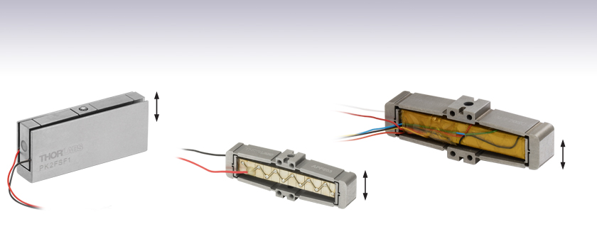
- Flexure Housing Amplifies Piezo Displacement
PK2FSF1
Amplified Piezoelectric Actuator with 220 µm Displacement, Open-Loop
APF503
Amplified Piezoelectric Actuator with 390 µm Displacement, Open-Loop
Direction of Translation
Direction of Translation
APF705C
Amplified Piezoelectric Actuator with 560 µm Displacement, Closed-Loop
Direction of Translation


Please Wait
| Piezo Actuator Comparisona | ||
|---|---|---|
| Item # | PK2F Series | APF Series |
| Drive Voltage Range (Max) | 0 to 75 V | -30 to 150 V |
| Max Displacement | 220 µm or 420 µm | 390 µm, 560 µm, 1500 µm, or 2500 µm |
| Mounting Options | M2.5 Taps and Top Ball Contact | Tapped Holes on Top, Bottom, Front, and Back |
- 詳しい仕様についてはTable G1.1とG2.1にあるInfoアイコン (
 ) を
) を
クリックするとご覧いただけます。

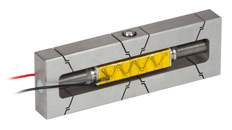
Click to Enlarge
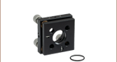
Figure 1.1 ピエゾアクチュエータが取り付けられたPK2Fシリーズのフレクシャーマウント(U字型保護カバーを取り外した状態)
特長
- フレクシャ機構付き筐体に入った多段チップ型ピエゾアクチュエータ
- ワイヤ付きで組み込みが容易
- 開ループシステムで用いる実験用途
- 組み込み用途(OEM用途)に適した製品
当社の増幅機構付きピエゾアクチュエータは、筐体のフレクシャーマウント内に多段チップ型ピエゾアクチュエータを取り付けた構成となっております。フレクシャーマウントがレバーアームとして機能し、多段チップ型ピエゾアクチュエータのフリーストローク変位量を増幅します。このアセンブリで得られる変位量はピエゾアクチュエータのみで得られる変位量よりも大幅に大きくなりますが、アクチュエータの速い応答速度と低い駆動電圧という特性は保たれます。変位はフレクシャーマウント内のピエゾアクチュエータによって生成されるため、バックラッシュが生じません。
PK2Fシリーズ
PK2Fシリーズの増幅機構付きピエゾアクチュエータは0~75 Vの駆動電圧に対応します。U字型の金属製保護カバーを有し、上部に取り付ける負荷とはボール接触をするようになっています。ピエゾアクチュエータにはワイヤが予め取り付けられています。赤のワイヤが接続されている電極は正電圧の端子に接続し、黒のワイヤが接続されている電極は接地してください。U字型の金属製カバーはピエゾアクチュエータとワイヤ接続部を保護しています。アクチュエータ本体の上部にあるタングステンカーバイド製の球面接触部により、移動軸に沿って精密に負荷をかけることができ、他の軸に不要な負荷がかかるのを防止します。また、M2.5タップ穴が2つ付いているので取り付けも簡単かつ確実です。アクチュエータの4つの側面はセラミックの絶縁層で覆われており、湿度から保護されています。このセラミック層は、エポキシ樹脂のコーティングを用いるよりも湿度に対して優れた保護性能を有しています。
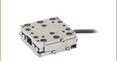
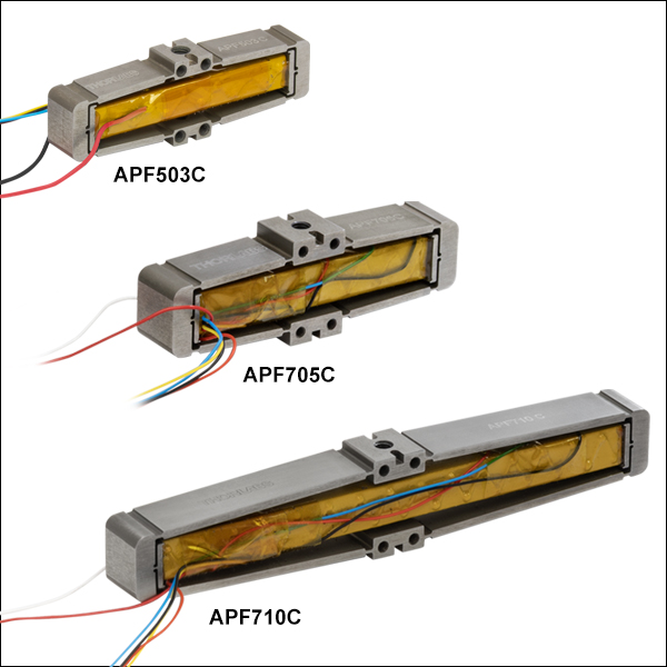
APFシリーズ
APFシリーズは-30~150 Vの電圧で駆動可能です。オープンフレーム型で部品を取り付けるためのタップ穴が複数付いているため、組み込み用途(OEM用途)に適しています。ピエゾアクチュエータには予めワイヤが取り付けられています。通常の使用では、黒のワイヤ(APF503)または白のワイヤ(APF705とAPF710)が接続されている電極は接地し、赤のワイヤには双極性電源を使用して-30 V~+150 Vの電圧を印加してください。双極性電源が利用できない場合は、黒または白のワイヤに+30 Vを印加し、赤のワイヤへの印加電圧を0~+180 Vの範囲で変化させることにより、全移動範囲をカバーできます。フレクシャー構造の筐体には、取付け用のタップ穴が上部と底部に1つずつ、前と後ろに4つずつ付いています。これらの取付け穴によりアクチュエータを柔軟にセットアップに組み込むことができますが、角度方向の共振を発生させないために、負荷をアクチュエータの移動軸に合わせて適切に取り付ける必要があります。
注:セットアップ構築の際には、静電気放電を避けるため、各ピエゾアクチュエータのワイヤをひとまとめにしたまま構築してください。静電気によりピエゾ素子が損傷する場合があります。
こちらのアクチュエータは、開ループコントローラのMDT69xBとKPC101、および閉ループコントローラのMPZ601とBPC30xに対応しています。しかし、これらのコントローラが供給できる駆動電圧は0~150 Vであるため、APFシリーズのピエゾアクチュエータの全移動範囲をカバーすることはできません。また、こちらのアクチュエータには歪ゲージが付いていないため、閉ループコントローラを使用する時に必要な位置のフィードバック情報は得られませんのでご注意ください。閉ループフィードバックが必要な場合には、当社の歪ゲージ付きピエゾアクチュエータをご検討ください。「取扱い」タブでは、ピエゾデバイスを実際に組み込む方法や、操作上の注意点、動作条件に基づいて寿命を予測するためのデータなどがご覧いただけます。
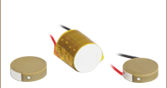
当社では共焼成積層型ピエゾアクチュエータもご提供しており、その最大変位量は4.6 µm~20.0 µmで、フィードバックが可能な歪ゲージ内蔵型もございます。接着された複数のPZTチップで構成されている多段チップ型ピエゾアクチュエータとは異なり、共焼成積層型ピエゾアクチュエータはPZTチップ層を1つのモノリシック構造に焼結した構造になっています。ピエゾアクチュエータの設計や機能についての詳細は、ピエゾ素子のチュートリアルのページをご覧ください。


当社におけるピエゾアクチュエータの製造について
ピエゾアクチュエータは当社の施設内で製造しており、各製造工程を当社が管理しています。これにより、特注や組み込み用途(OEM用途)のデバイスなどを高品質かつ安価でご提供することが可能になります。当社におけるピエゾアクチュエータの製造工程の概要は以下の通りです。詳細については、ピエゾ素子の製造能力のページをご参照ください。
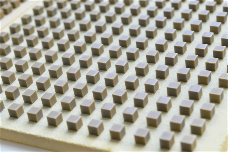
- チタン酸ジルコン酸鉛(PZT)またはBiScO3-PbTiO3 (BSPT)の粉末で形成されたフレキシブルシートからブロックを作成
- 各シート上に内部電極をスクリーン印刷
- 印刷したシートを積み重ねて層を形成
- 層状のシートを等方プレス
- ブロックを個々の素子にダイシング(切断)
- 素子に熱処理を施して溶媒やバインダ材の残留物を除去
- 素子を焼結して圧電性の圧粉を融着させ、PZTまたはBSPT結晶を生成
- 厳しい寸法公差(±5 µm)を得るために、素子をラップ研磨
- 素子に外部電極をスクリーン印刷
- 素子を分極処理して、PZTまたはBSPT結晶の軸を揃える
Displacement vs. Voltage Curves
The displacement vs. voltage hysteresis curves for the amplified piezos are available here. The hysteresis is a result of some variability in the orientations of the ferroelectric domain polarizations within the PZT crystal. During fabrication, the polarizations of the large majority of crystal domains are aligned along the same direction by applying a strong electric field, which is considerably stronger than the one applied during device operation, across the PZT crystal. It is the contribution of other, extrinsic, ferroelectric domains that are the source of the hysteresis, and the magnitudes of their contributions depend on factors that include the mechanical pre-loading of the actuator, the temperature of the device, the control frequency, the dimensions of the device, and the history of the voltage signal driving the device.
To view the plots, click More [+] in the appropriate row below.
| PK2F Series Hysteresis |
|---|
 Click to Enlarge The displacement response of the PK2FSF1 amplified PZT actuator to applied voltage is plotted above. To view an Excel file that contains these data values, please click here.  Click to Enlarge The displacement response of the PK2FVF1 amplified PZT actuator to applied voltage is plotted above. To view an Excel file that contains these data values, please click here. |
| APF503(C), APF705(C), and APF710(C) Hysteresis |
|---|
|
In these tests, each actuator was given a 15 g load and held at an ambient temperature of 20 °C. The voltage was first increased from 0 V to 150 V, then decreased to -30 V, and finally returned to 0 V. The initial and final positions are offset slightly due to hysteresis.
_Displacement_G1-780.gif) Click to Enlarge The displacement response of the APF503(C) amplified piezo actuator to applied voltage is plotted above. To view an Excel file that contains these data values, please click here. _Displacement_G1-780.gif) Click to Enlarge The displacement response of the APF705(C) amplified piezo actuator to applied voltage is plotted above. To view an Excel file that contains these data values, please click here. _Displacement_G1-780.gif) Click to Enlarge The displacement response of the APF710(C) amplified piezo actuator to applied voltage is plotted above. To view an Excel file that contains these data values, please click here. |
| APFH720 Hysteresis |
|---|
|
The displacement response of the APFH720 amplified piezo actuator to applied voltage is plotted above. The left graph shows a voltage cycle from 0 to 150 V, while the right graph shows a voltage cycle over the full -30 to 150 V range. To view an Excel file that contains these data values, please click here. |


Displacement vs. Command Position for Closed-Loop Actuators
The displacement vs. command position curves for the closed-loop amplified piezos are available here. When operated using their strain gauge feedback capabilities, hysteresis is almost completely eliminated. These curves show the small deviation remaining between the command position of each piezo and the actual position read back while increasing and discreasing displacement.
To view the plots, click More [+] below.
| APF503C, APF705C, and APF710C Displacement vs. Command Position |
|---|
|
In these tests, the position read back by the strain gauge is plotted against the command position sent to the actuator for expanding in 10 steps and then contracting back to the 0 position in another 10 steps. Due to feedback from the strain gauge, the displacement and command position remain close or equal throughout the full stroke of the actuator.
 Click to Enlarge The displacement response of the APF503C closed-loop amplified piezo actuator to the command position is plotted above. To view an Excel file that contains these data values, please click here.  Click to Enlarge The displacement response of the APF705C closed-loop amplified piezo actuator to the command position is plotted above. To view an Excel file that contains these data values, please click here.  Click to Enlarge The displacement response of the APF710C closed-loop amplified piezo actuator to the command position is plotted above. To view an Excel file that contains these data values, please click here. |
Resonant Frequency vs. Load Curves
A parameter of significance to many applications is the rate at which the piezoelectric actuator changes its length. This dimensional rate of change depends on a number of factors, including the bandwidth of the piezoelectric actuator (its resonant frequency), the absolute maximum bandwidth of the driver (its slew rate), the maximum current the piezoelectric device can produce, the capacitance of the piezoelectric stack, and the amplitude of the driving signal. The length of the voltage-induced extension is a function of the amplitude of the applied voltage driving the actuator and the length of the piezoelectric stack. The higher the capacitance, the slower the dimensional change of the actuator.
Quick changes in the applied voltage result in fast dimensional changes to the piezoelectric stack. Assuming the driving voltage signal resembles a step function, the minimum time, Tmin, required for the length of the actuator to transition between its initial value and that corresponding to the final applied voltage is approximately 1/3 the period of resonant frequency. If there is no load applied to the piezoelectric stack, its resonance frequency is ƒo and its minimum response time is:

After reaching this nominal extension, there will follow a damped oscillation in the length of the actuator around this position. Controls can be implemented to mitigate this oscillation, but doing so may slow the response of the actuator.
Applying a load to the actuator will reduce the resonant frequency of the piezoelectric stack. Given the unloaded resonant frequency of the actuator, the mass of the stack, m, and the mass of the load, M, the loaded resonant frequency (ƒo') may be estimated using the following equation:
 .
.The unloaded resonant frequencies of the amplified piezos can be seen by clicking More [+] in the rows below.
| PK2F Series Resonant Frequency vs. Load |
|---|
 Click to Enlarge The resonant frequency of the PK2FSF1 amplified PZT actuator as a function of the applied load is plotted above. To view an Excel file that contains these data values, please click here.  Click to Enlarge The resonant frequency of the PK2FVF1 amplified PZT actuator as a function of the applied load is plotted above. To view an Excel file that contains these data values, please click here. |
| APF503(C), APF705(C), and APF710(C) Resonant Frequency vs. Load |
|---|
 Click to Enlarge Figure 2.1 Linear resonance occurs when the mounted load is symmetric with respect to the top mounting hole, or "on axis.". Angular resonance occurs when a load is mounted asymmetrically with respect to the top mounting hole, or "off axis." Due to the geometry of the flexure housing, the actuators are prone to resonance in the yaw of the mounting surface as a result of off-axis mounting. To minimize angular resonance modes, keep the load's center of mass as close to the top mounting hole as possible. _Frequency_G1-780.gif) Click to Enlarge The resonant frequency of the APF503(C) amplified PZT actuator as a function of the applied load is plotted above. To view an Excel file that contains these data values, please click here. _Frequency_G1-780.gif) Click to Enlarge The resonant frequency of the APF705(C) amplified PZT actuator as a function of the applied load is plotted above. To view an Excel file that contains these data values, please click here. _Frequency_G1-780.gif) Click to Enlarge The resonant frequency of the APF710(C) amplified PZT actuator as a function of the applied load is plotted above. To view an Excel file that contains these data values, please click here. |
| APFH720 Resonant Frequency vs. Load |
|---|
|
Click to Enlarge Figure 2.2 Linear resonance occurs when the mounted load is symmetric with respect to the top mounting hole, or "on axis.". Angular resonance occurs when a load is mounted asymmetrically with respect to the top mounting hole, or "off axis." Due to the geometry of the flexure housing, the actuator is prone to resonance in the yaw of the mounting surface as a result of off-axis mounting. To minimize angular resonance modes, keep the load's center of mass as close to the top mounting hole as possible.  Click to Enlarge The resonant frequency of the APFH720 amplified PZT actuator as a function of the applied load is plotted above. To view an Excel file that contains these data values, please click here. |
Click to Enlarge
Figure 3.1 U字型保護カバーを外したPK2Fシリーズのフレクシャーマウント
使用上の注意点
電源の接続
PK2Fシリーズ:赤のワイヤが接続されている電極は正電圧の端子に接続し、黒のワイヤが接続されている電極は接地してください。ワイヤ間に印加する電圧範囲は0 V~+75 Vにしてください。負の電圧を印加すると機械的に故障する場合があります。
APFシリーズ:通常は黒のワイヤ(APF503(C)とAPFH720)または白のワイヤ(APF705(C)とAPF710(C))が接続されている電極は接地し、赤のワイヤには双極性電源を使用して-30 V~+150 Vの電圧を印加してください。双極性電源が利用できない場合は、黒または白のワイヤに+30 Vを印加し、赤のワイヤへの印加電圧を0~ +180 Vの範囲で変化させることにより、全移動範囲をカバーできます。
注:駆動後のピエゾアクチュエータには電荷が蓄積しています。正と負の電極を直接接続すると放電し、火花の発生や、さらには故障する危険性もあります。 この電荷を解放するために、当社では電極の間に抵抗(>1 kΩ)を挿入することをお勧めしています。/p>
ピエゾアクチュエータへの負荷の取付け
PK2Fシリーズ:負荷は球面の接触部に取り付けなければなりません。デバイスのその他の面に負荷を取り付けると機械的な故障につながる場合があります。
APFシリーズ:負荷はアクチュエータ筐体の上部または側面に付いているタップ穴に取り付けてください。角度方向に共振させないために、負荷がアクチュエータの移動軸上にくるように適切に取り付けてください。
リード線の電極へのはんだ付け
リード線を電極に再接続する場合、はんだ付けの温度は370 °C以下、時間は2秒以内で行ってください。リード線は電極の中心にはんだ付けし、加熱するのはできるだけ小さな範囲に留めてください。
高い周波数で動作させる場合
高い周波数で動作させるには、外部に温度制御システムを取り付けてデバイスを冷やす必要がある場合があります。高い周波数でピエゾ素子を動作させると、デバイスの内部温度が上昇します。デバイスの温度は、仕様の最大動作温度を超えないようにしてください。
DC電圧で駆動したときのデバイスの推定寿命
ピエゾデバイスの寿命は動作温度、印加電圧ならびに相対湿度の関数となります。DC電圧が印加されているときには、寿命はピエゾデバイスの電極で発生する、湿度による電解反応によって短くなります。この反応により水素が発生し、陰極から陽極に向けて金属のデンドライト(樹枝状結晶)が形成されます。電解反応により遊離した水素は、ピエゾ素子と化学反応を起こして劣化させます。形成されたデンドライトは陰極と陽極を電気的に接続することになり、その結果として漏れ電流のレベルが上昇します。ピエゾデバイスが故障しているかどうかは、以下の試験では漏れ電流レベルが規定の閾値よりも高くなっているかどうかで判断しています。
当社のピエゾデバイスは4面がセラミック製の防湿層で覆われているため、湿度がデバイスの寿命に及ぼす影響を最小限に抑えられています。ピエゾデバイスの寿命測定についてのご要望を受けて、当社ではセラミックで絶縁された低電圧駆動のピエゾデバイスに対する環境試験を実施しました。その結果を用いて、平均故障時間(MTTF)を見積るための単純なモデルを作成しました。前提として、湿度、温度、印加電圧が既知である必要があります。推定MTTFは、動作温度、相対湿度、印加電圧に対応する3つの係数の積となります。 各パラメータに対応する係数は下記のグラフから読むこともできますし、あるいはそのデータをダウンロードして適当に内挿を行うこともできます。ここで電圧については印加電圧と最大定格電圧の比の関数として表しています。
下記の3つのグラフにおける曲線の実線部分は当社が試験を実施した範囲を示しています。これらの測定範囲はよく使用される環境条件を考慮して設定しました。実線から続いている点線部分は外挿値で、デバイスを使用する際に遭遇する可能性のある環境条件の範囲を示しています。
寿命推定のためのMTTF計算式: MTTF = fV * fT * fH
相対湿度、デバイス温度、DC駆動電圧がわかれば、デバイスの寿命が推定可能です。寿命は、電圧、温度および湿度に係る各係数の積で与えられ、それらはFigure 3.2、3.3、3.4から求めることができます。
例えば、PK2FSF1タイプのデバイスを、相対湿度75%の環境下で、電圧60 V、温度30 °Cで駆動する場合:
- Figure 3.3から、電圧係数は427(PK2FSF1の最大定格電圧 Vmaxは75 V、よってV/Vmax = 60 V / 75 V = 0.80)となります。
- Figure 3.2で、温度係数は83です。
- Figure 3.4で、湿度係数は2.8です。
よって、MTTF = 472 * 83 * 2.8 = 99234.8時間となり、11年以上となります。
上のグラフで示しているデータはピエゾアクチュエータPK2FSF1を使用して取得しました。こちらでご紹介しているほかのアクチュエータも同様の性能を示します。

これらの温度、電圧および湿度の係数を得るためのデータは、6種類の異なる動作環境下での試験による測定値をもとに分析され、グラフ化されています。異なる10個の専用デバイスのセットを、それぞれ異なる駆動電圧、デバイス温度、相対湿度の組合せによる環境下で試験を行いました。デバイスに閾値100 nAを上回るレベルの漏れ電流が発生した時点で、故障としました。温度、湿度および電圧がそれぞれ寿命に与える影響は以下の関係式を仮定して求めています:
- MTTF = fV(V) * fT(T) * fH(H)
- 電圧のべき乗に比例: fV(V) = A1Vb1
- 相対湿度に対しては、指数関数で変化: fH(T) = A2ecH
- 温度に対しては、アレニウスの式: fT(H) = A3eb2/T
ここでA1、A2、A3、b1、b2、cは測定データの分析により決定される定数、VはDC駆動電圧、Tはデバイスの温度、Hは相対湿度です。MTTFと各係数との数学的関係式が異なるので、MTTFの各係数への依存性を決定できます。そのようにして得られたのが上のグラフです。グラフ内の青い網掛け部分の曲線は、実験データです。曲線の点線部分は外挿値です。
これらのデバイスの寿命試験は引き続き実施されています。追加データは準備ができ次第掲載いたします。
| Posted Comments: | |
jdelia
(posted 2024-10-17 01:28:32.0) Thank you for contacting Thorlabs. These actuators can be driven with the MDT69xB or KPC101 open-loop controllers, and the MPZ601 or BPC30x closed-loop controllers. A member from your local technical support team will contact you directly to help you select a controller and provide a quote. These actuators do not include sensing for closed-loop control (even if a closed-loop controller is used). We can customize amplified actuators with strain gauges, if you are interested, please let our colleague who contacted you know. Taeguk Um
(posted 2023-02-19 05:34:16.937) Hi, I'm taeguk Um in KAIST, KOREA.
I want to know more about APFH720.
In my research, I want reciprocating linear motion with 3 mm stroke and several kHz (about 3kHz). Can I achieve the performance I want with the APFH720?
For reference, there was a thesis that experimented with 5 kHz using this product. Is it okay to use it like this?
Sincerely,
Taeguk Um cdolbashian
(posted 2023-04-03 10:41:39.0) These piezo actuators are supposed to operate with no higher than 1/3 of the resonant frequency. (Piezo is prone to overheating and failure at high frequencies.) Given the parameters of APFH720 (151Hz resonant frequency @5g on-axis load; 2.5mm free stroke), 5kHz driving is possible but the voltage/stroke needs to be limited to a low level. We will get in touch with you directly to discuss this further GIANLUCA GAGLIARDI
(posted 2022-05-24 10:57:54.5) We purchased a PK2FSF1 actuator. We drove it always with your Thorlabs piezo driver. Suddenly, the actuator stopped working as expected and despite voltage applied no movement manifests. Apparently, the piezo inside was not working but we tried without external voltage amplifier, using a function generator only, and the piezo played sound clearly.
Do you have any suggestion or test to maek?
In case the device is dead, I wonder if we have still a chance to repair it mounting a new piezo element inside.
Gianluca cdolbashian
(posted 2022-05-27 12:43:11.0) Thank you for contacting Thorlabs. It's worth checking the capacitance and resistance of the piezo element, the piezo element may be damaged if the capacitance is less than 85% of the specified value (9.0 uF), or if its resistance is in the hundreds or thousands of ohms. It is also worth checking if the driver still works well. In case the device is damaged, please feel free to contact the local Tech Support team (in your case Europe@thorlabs.com) to send the unit back for further inspection/repair. jaakko.palosaari
(posted 2016-08-25 07:00:17.043) Can the piezoelectric actuator PKFVF1 be driven with a square wave signal(Vpp:0 to +75) ? johng
(posted 2015-09-11 13:13:22.29) This is a very good product. Would you have a chart of the freq. response verses load?
Thank you,
JOhn besembeson
(posted 2015-10-05 10:59:19.0) Response from Bweh at Thorlabs USA: We don't have such a graph at this time. I will follow-up regarding estimating the resonant frequency and piezo bandwidth for your particular case. |

 ズーム
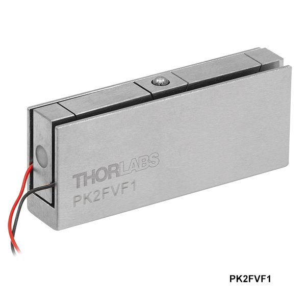
ズーム- フレクシャ構造の筐体(U字型保護カバー付き)に入った増幅機構付きピエゾアクチュエータ
- 上部のタングステンカーバイド製球面接触部に負荷の取り付け
- 底部にM2.5ネジ穴が2つ
- 正電圧で負荷を外側に押す力が発生
| Table G1.1 Specifications | |||||||
|---|---|---|---|---|---|---|---|
| Item #a | Infob | Displacement (Free Stroke) | Outer Dimensionsc | Max Pulling Force | Max Pushing Force | Resonant Frequency | Capacitance |
| PK2FSF1 | 220 µm | 22.3 x 11.0 x 53.4 mm (0.88" x 0.43" x 2.10") | 5 N | 100 N | 1.0 kHz | 9.0 µF ± 15% | |
| PK2FVF1 | 420 µm | 22.3 x 11.0 x 53.4 mm (0.88" x 0.43" x 2.10") | 5 N | 100 N | 1.0 kHz | 16.5 µF ± 15% | |

 ズーム
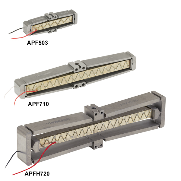
ズーム- オープンフレームのフレクシャー筐体に入った増幅機構付きピエゾアクチュエータ
- 筐体の前後上下に取付け用ネジ穴
- 正電圧で負荷を内側に引っ張る力(APF503、APF705、APF710)、または外側に押す力(APFH720)が発生
| Table G2.1 Specifications | |||||||
|---|---|---|---|---|---|---|---|
| Item # | Infoa | Displacement (Free Stroke) | Outer Dimensionsb | Max Pulling Force | Max Pushing Force | Resonant Frequencyc | Capacitance |
| APF503 | 390 µm | 14.0 x 7.0 x 44.0 mm (0.55" x 0.28" x 1.73") | 10 Nd | 10 Ne | 385 Hz | 3.5 µF | |
| APF705 | 560 µm | 18.0 x 10.0 x 55.0 mm (0.71" x 0.39" x 2.17") | 25 Nd | 20 Ne | 315 Hz | 8.0 µF | |
| APF710 | 1500 µm | 18.0 x 10.0 x 100.0 mm (0.71" x 0.39" x 3.94") | 55 Nd | 20 Ne | 185 Hz | 16.0 µF | |
| APFH720f | 2500 µm | 30.0 x 13.0 x 120.0 mm 1.18" x 0.51" x 4.72" | 3 Ne | 30 Nd | 151 Hz | 16.5 µF ± 15%g | |

 ズーム
ズーム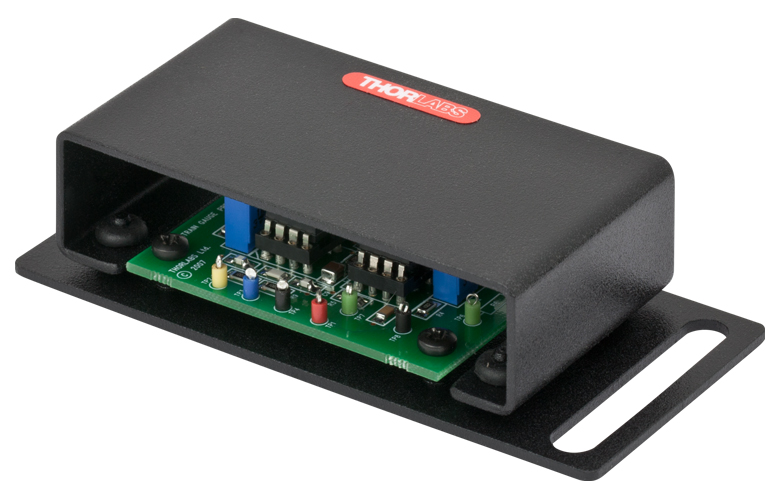
Click to Enlarge
Figure G3.2 The AMP002 Strain Gauge Pre-Amp Circuit
Click to Enlarge
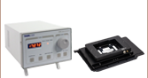
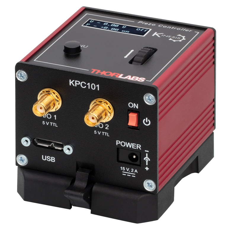
Figure G3.1 The KPC101 Piezo Controller and Strain Gauge Reader
Recommended Controller Configuration:
KPC101 & AMP002
- Closed-Loop Operation and Strain Gauge Amplification
- -10 to +150 V Piezo Drive Voltage
- 1 kHz Drive Bandwidth
- Amplified Piezo in Open-Frame Flexure Housing
- Threaded Mounting Holes on Top, Bottom, Front, and Back
- Positive Voltage Pulls Load Inward
| Table G3.3 Specifications | |||||||
|---|---|---|---|---|---|---|---|
| Item # | Infoa | Displacement (Free Stroke) |
Outer Dimensionsb | Max Pulling Force |
Max Pushing Force |
Resonant Frequencyc |
Capacitance |
| APF503C | 390 µm | 14.0 x 7.00 x 44.0 mm (0.56" x 0.276" x 1.73") |
10 Nd | 10 Ne | 385 Hz | 3.5 µF | |
| APF705C | 560 µm | 18.0 x 10.00 x 55.0 mm (0.71" x 0.394" x 2.17") |
25 Nd | 20 Ne | 315 Hz | 8.0 µF | |
| APF710C | 1500 µm | 18.0 x 10.00 x 100.0 mm (0.71" x 0.394" x 3.94") |
55 Nd | 20 Ne | 185 Hz | 16.0 µF | |
- Click the info icon () for complete specifications.
- Not Including Wires
- 5 g, On-Axis Load
- When Increasing Voltage
- When Decreasing Voltage