 Products Home
エッジパスフィルター、ハードコーティング
- High-Performance Edgepass Filters
- OD > 5 in Rejection Region
- Transmission > 90% in Transmission Region
- Hard-Coated Dielectric Coating on UV Fused Silica
Transmission Direction Indicator
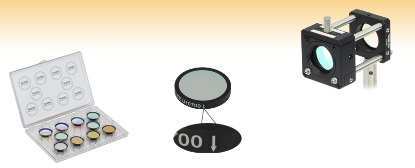
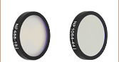
FKLPVIS
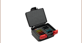
Hard-Coated Visible Longpass Filter Kit
FELH0700
Longpass
Cut-On: 700 nm
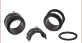
FELH0650 Longpass Filter in a CFH2 Filter Holder
(Mounts and Assemblies Sold Separately)


Please Wait
特長
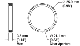
- 外径:Ø25 mm(開口:Ø21.1 mm)
- ロングパスおよびショートパスフィルタ
- 阻止波長領域で優れた透過阻止特性 (OD>5)
- 側面に推奨する透過方向が刻印
- ハードコーティングロングパスフィルタまたはショートパスフィルタが10個入りのフィルターキットもご用意
- 蛍光用途での発光フィルタやラマン分光フィルタに適した製品
- 特注のエッジパスフィルタのサイズについては、当社までご連絡ください
ハードコーティングエッジパスフィルタは高性能フィルタで、特定のスペクトルの分離の用途で非常に便利です。 この高性能フィルタの光学濃度(OD)は、阻止波長領域においてOD>5で、透過領域における透過率は>90%です。これらフィルタの阻止波長領域および透過領域については「仕様」タブをご参照ください。各フィルタの損傷閾値の仕様については下表をご参照ください。
これらのエッジパスフィルタは、UV溶融石英製で、耐久性が高く、ハードコーティングされた誘電体コーティングが施されています。 薄膜層の構造は、基本的に1/4波長層を積層したもので、スペクトルの分離には干渉効果を利用しています(透過率の詳細については「仕様」タブをご参照ください)。フィルタのコーティングは高密度であるため、1枚の基板上に構築することができ、それにより安定した長寿命のフィルタが実現されています。このコーティングは、高品質の光学素子を使用する際に必要とされる通常のクリーニングや取扱いに耐えられます。耐久性や透過率の向上など、ソフトコーティングフィルタと比較してハードコーティングフィルタが優れている点については、「比較」タブをご覧ください。
各フィルタは、黒色アルマイト加工が施され、設計伝播方向を示す矢印が刻印されたリングに取り付けられています。 このリングが付いていることで取扱いがしやすく、散乱も制限するので透過阻止性能(OD値)も向上します。 このフィルタは、当社のフィルターマウントやホイールに取り付けることができます。 マウントにはネジ切り加工が施されていないので、このフィルタを当社の内ネジ付きSM1レンズチューブに取り付ける際は、Ø25.4 mm(Ø1インチ)固定リングが必要になります。 尚、フィルタに損傷を与える可能性が非常に高いため、マウントからフィルタを取り外すことはお勧めいたしません。
こちらのロングパスおよびショートパスフィルタは、それぞれ10個入りのキットでもご用意しております。
| Longpass | Shortpass | |
|---|---|---|
| Transmission Region | See Table Below to Left | See Table Below to Right |
| Transmission | > 90% (Absolute)a | |
| Cut-on or Cut-off Tolerance | ±3 nm | < 0.75% of Cut-off λ |
| Rejection Region | See Table Below to Left | See Table Below to Right |
| Optical Density (OD) in Rejection Region | OD > 5 (Absolute) | |
| Transmitted Wavefront Error | λ/4 at 632.8 nmb | |
| Slope Tolerancec | < 1.0% | |
| Construction | Hard-Coated Dielectric on UVFS Substrate | |
| Surface Quality | 40-20 Scratch-Dig | |
| Substrate Material | UV Fused Silicad | |
| Diameter | 25.0 mm (0.98") | |
| Clear Aperture | Ø0.83" (Ø21.1 mm) | |
| Thickness | 0.14" (3.5 mm) | |
| Substrate Thickness | 0.08" (2 mm) | |
| Hard-Coated Shortpass Filters | ||||
|---|---|---|---|---|
| Item # | Cut-Off λ | Transmission Region (T>90%) | Rejection Region (OD>5) | Transmission Dataa |
| FESH0450 | 450 nm | 400 - 444 nm | 456 - 1200 nm | |
| FESH0500 | 500 nm | 400 - 494 nm | 506 - 1200 nm | |
| FESH0550 | 550 nm | 400 - 543 nm | 557 - 1200 nm | |
| FESH0600 | 600 nm | 400 - 592 nm | 608 - 1200 nm | |
| FESH0650 | 650 nm | 400 - 640 nm | 660 - 1200 nm | |
| FESH0700 | 700 nm | 400 - 690 nm | 711 - 1200 nm | |
| FESH0750 | 750 nm | 400 - 740 nm | 761 - 1200 nm | |
| FESH0800 | 800 nm | 500 - 789 nm | 811 - 1500 nm | |
| FESH0850 | 850 nm | 500 - 839 nm | 861 - 1500 nm | |
| FESH0900 | 900 nm | 550 - 880 nmb | 920 - 1500 nm | |
| FESH0950 | 950 nm | 575 - 930 nmc | 970 - 1500 nm | |
| FESH1000 | 1000 nm | 500 - 987 nm | 1013 - 1500 nm | |
Click for Details
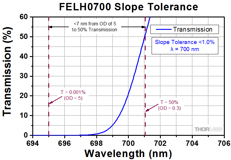
傾斜の公差は、光学濃度(OD)5(T ~0.001%)から透過率50%(OD~0.3)への移行に必要なカットオンまたはカットオフ波長の割合(%)として定義されています。この場合、傾斜の公差は<1%と見積もられます。また、このデータセットはOD5から透過率50%への移行に必要な波長範囲がおおよそ6 nmと示しています。
| Hard-Coated Longpass Filters | |||||
|---|---|---|---|---|---|
| Item # | Cut-On λ | Transmission Region (T>90%) | Rejection Region (OD>5) | Transmission Dataa | |
| FELH0400 | 400 nm | 407 - 2150 nm | 200 - 393 nm | ||
| FELH0450 | 450 nm | 457 - 2150 nm | 200 - 443 nm | ||
| FELH0500 | 500 nm | 508 - 2150 nm | 200 - 492 nm | ||
| FELH0550 | 550 nm | 559 - 2150 nm | 200 - 542 nm | ||
| FELH0600 | 600 nm | 609 - 2150 nm | 200 - 591 nm | ||
| FELH0650 | 650 nm | 660 - 2150 nm | 200 - 641 nm | ||
| FELH0700 | 700 nm | 710 - 2150 nm | 200 - 690 nm | ||
| FELH0750 | 750 nm | 761 - 2150 nm | 200 - 740 nm | ||
| FELH0800 | 800 nm | 812 - 2150 nm | 200 - 789 nm | ||
| FELH0850 | 850 nm | 861 - 2150 nm | 200 - 839 nm | ||
| FELH0900 | 900 nm | 912 - 2150 nm | 200 - 888 nm | ||
| FELH0950 | 950 nm | 962 - 2150 nm | 200 - 938 nm | ||
| FELH1000 | 1000 nm | 1013 - 2150 nm | 200 - 987 nm | ||
| FELH1050 | 1050 nm | 1063 - 2150 nm | 200 - 1037 nm | ||
| FELH1100 | 1100 nm | 1114 - 2150 nm | 200 - 1086 nm | ||
| FELH1150 | 1150 nm | 1164 - 2150 nm | 200 - 1136 nm | ||
| FELH1200 | 1200 nm | 1215 - 2150 nm | 200 - 1185 nm | ||
| FELH1250 | 1250 nm | 1265 - 2150 nm | 200 - 1235 nm | ||
| FELH1300 | 1300 nm | 1316 - 2150 nm | 200 - 1284 nm | ||
| FELH1350 | 1350 nm | 1366 - 2150 nm | 200 - 1334 nm | ||
| FELH1400 | 1400 nm | 1417 - 2150 nm | 200 - 1383 nm | ||
| FELH1450 | 1450 nm | 1467 - 2150 nm | 200 - 1433 nm | ||
| FELH1500 | 1500 nm | 1518 - 2150 nm | 200 - 1482 nm | ||
光学濃度に関する式:![]()
| Damage Thresholds Specifications | |
|---|---|
| Item # | Damage Threshold |
| FELH0550 | 1.0 J/cm2 (532 nm, 10 ns, 10 Hz, Ø0.472 mm) |
| FELH0950 | 0.25 J/cm2 (1064 nm, 10 ns, 10 Hz, Ø1.010 mm) |
| FELH1000 | 3.75 J/cm2 (1064 nm, 10 ns, 10 Hz, Ø0.516 mm) |
| FELH1050 | 0.1 J/cm2 (532 nm, 10 ns, 10 Hz, Ø0.360 mm) |
| FESH0600 | 3 J/cm2 (1064 nm, 10 ns, 10 Hz, Ø0.429 mm) |
| FESH0700 | 1.0 J/cm2 (532 nm, 10 ns, 10 Hz, Ø0.472 mm) |
| FESH1000 | 7.5 J/cm2 (1064 nm, 10 ns, 10 Hz, Ø0.516 mm) |
当社のエッジパスフィルタ(一部抜粋)の損傷閾値
右の仕様は、当社のハードコーティング付きエッジパスフィルタ(一部抜粋)の測定値です。
レーザによる損傷閾値について
このチュートリアルでは、レーザ損傷閾値がどのように測定され、使用する用途に適切な光学素子の決定にその値をどのようにご利用いただけるかを総括しています。お客様のアプリケーションにおいて、光学素子を選択する際、光学素子のレーザによる損傷閾値(Laser Induced Damage Threshold :LIDT)を知ることが重要です。光学素子のLIDTはお客様が使用するレーザの種類に大きく依存します。連続(CW)レーザは、通常、吸収(コーティングまたは基板における)によって発生する熱によって損傷を引き起こします。一方、パルスレーザは熱的損傷が起こる前に、光学素子の格子構造から電子が引き剥がされることによって損傷を受けます。ここで示すガイドラインは、室温で新品の光学素子を前提としています(つまり、スクラッチ&ディグ仕様内、表面の汚染がないなど)。光学素子の表面に塵などの粒子が付くと、低い閾値で損傷を受ける可能性があります。そのため、光学素子の表面をきれいで埃のない状態に保つことをお勧めします。光学素子のクリーニングについては「光学素子クリーニングチュートリアル」をご参照ください。
テスト方法
当社のLIDTテストは、ISO/DIS 11254およびISO 21254に準拠しています。
初めに、低パワー/エネルギのビームを光学素子に入射します。その光学素子の10ヶ所に1回ずつ、設定した時間(CW)またはパルス数(決められたprf)、レーザを照射します。レーザを照射した後、倍率約100倍の顕微鏡を用いた検査で確認し、すべての確認できる損傷を調べます。特定のパワー/エネルギで損傷のあった場所の数を記録します。次に、そのパワー/エネルギを増やすか減らすかして、光学素子にさらに10ヶ所レーザを照射します。このプロセスを損傷が観測されるまで繰返します。損傷閾値は、光学素子が損傷に耐える、損傷が起こらない最大のパワー/エネルギになります。1つのミラーBB1-E02の試験結果は以下のようなヒストグラムになります。
上の写真はアルミニウムをコーティングしたミラーでLIDTテストを終えたものです。このテストは、損傷を受ける前のレーザのエネルギは0.43 J/cm2 (1064 nm、10 ns pulse、 10 Hz、Ø1.000 mm)でした。
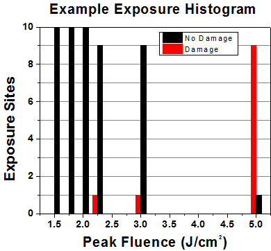
| Example Test Data | |||
|---|---|---|---|
| Fluence | # of Tested Locations | Locations with Damage | Locations Without Damage |
| 1.50 J/cm2 | 10 | 0 | 10 |
| 1.75 J/cm2 | 10 | 0 | 10 |
| 2.00 J/cm2 | 10 | 0 | 10 |
| 2.25 J/cm2 | 10 | 1 | 9 |
| 3.00 J/cm2 | 10 | 1 | 9 |
| 5.00 J/cm2 | 10 | 9 | 1 |
試験結果によれば、ミラーの損傷閾値は 2.00 J/cm2 (532 nm、10 ns pulse、10 Hz、 Ø0.803 mm)でした。尚、汚れや汚染によって光学素子の損傷閾値は大幅に低減されるため、こちらの試験はクリーンな光学素子で行っています。また、特定のロットのコーティングに対してのみ試験を行った結果ではありますが、当社の損傷閾値の仕様は様々な因子を考慮して、実測した値よりも低めに設定されており、全てのコーティングロットに対して適用されています。
CWレーザと長パルスレーザ
光学素子がCWレーザによって損傷を受けるのは、通常バルク材料がレーザのエネルギを吸収することによって引き起こされる溶解、あるいはAR(反射防止)コーティングのダメージによるものです[1]。1 µsを超える長いパルスレーザについてLIDTを論じる時は、CWレーザと同様に扱うことができます。
パルス長が1 nsと1 µs の間のときは、損傷は吸収、もしくは絶縁破壊のどちらかで発生していると考えることができます(CWとパルスのLIDT両方を調べなければなりません)。吸収は光学素子の固有特性によるものか、表面の不均一性によるものかのどちらかによって起こります。従って、LIDTは製造元の仕様以上の表面の質を有する光学素子にのみ有効です。多くの光学素子は、ハイパワーCWレーザで扱うことができる一方、アクロマティック複レンズのような接合レンズやNDフィルタのような高吸収光学素子は低いCWレーザ損傷閾値になる傾向にあります。このような低い損傷閾値は接着剤や金属コーティングにおける吸収や散乱によるものです。
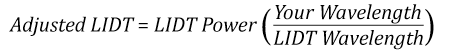
線形パワー密度におけるLIDTに対するパルス長とスポットサイズ。長パルス~CWでは線形パワー密度はスポットサイズにかかわらず一定です。 このグラフの出典は[1]です。

繰返し周波数(prf)の高いパルスレーザは、光学素子に熱的損傷も引き起こします。この場合は吸収や熱拡散率のような因子が深く関係しており、残念ながらprfの高いレーザが熱的影響によって光学素子に損傷を引き起こす場合の信頼性のあるLIDTを求める方法は確立されておりません。prfの大きいビームでは、平均出力およびピークパワーの両方を等しいCW出力と比較する必要があります。また、非常に透過率の高い材料では、prfが上昇してもLIDTの減少は皆無かそれに近くなります。
ある光学素子の固有のCWレーザの損傷閾値を使う場合には、以下のことを知る必要があります。
- レーザの波長
- ビーム径(1/e2)
- ビームのおおよその強度プロファイル(ガウシアン型など)
- レーザのパワー密度(トータルパワーをビームの強度が1/e2の範囲の面積で割ったもの)
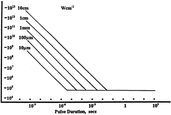
ビームのパワー密度はW/cmの単位で計算します。この条件下では、出力密度はスポットサイズとは無関係になります。つまり、スポットサイズの変化に合わせてLIDTを計算し直す必要がありません(右グラフ参照)。平均線形パワー密度は、下の計算式で算出できます。
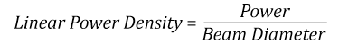
ここでは、ビーム強度プロファイルは一定であると仮定しています。次に、ビームがホットスポット、または他の不均一な強度プロファイルの場合を考慮して、おおよその最大パワー密度を計算する必要があります。ご参考までに、ガウシアンビームのときはビームの強度が1/e2の2倍のパワー密度を有します(右下図参照)。
次に、光学素子のLIDTの仕様の最大パワー密度を比較しましょう。損傷閾値の測定波長が光学素子に使用する波長と異なっている場合には、その損傷閾値は適宜補正が必要です。おおよその目安として参考にできるのは、損傷閾値は波長に対して比例関係であるということです。短い波長で使う場合、損傷閾値は低下します(つまり、1310 nmで10 W/cmのLIDTならば、655 nmでは5 W/cmと見積もります)。
この目安は一般的な傾向ですが、LIDTと波長の関係を定量的に示すものではありません。例えば、CW用途では、損傷はコーティングや基板の吸収によってより大きく変化し、必ずしも一般的な傾向通りとはなりません。上記の傾向はLIDT値の目安として参考にしていただけますが、LIDTの仕様波長と異なる場合には当社までお問い合わせください。パワー密度が光学素子の補正済みLIDTよりも小さい場合、この光学素子は目的の用途にご使用いただけます。
当社のウェブ上の損傷閾値の仕様と我々が行った実際の実験の値の間にはある程度の差があります。これはロット間の違いによって発生する誤差を許容するためです。ご要求に応じて、当社は個別の情報やテスト結果の証明書を発行することもできます。損傷解析は、類似した光学素子を用いて行います(お客様の光学素子には損傷は与えません)。試験の費用や所要時間などの詳細は、当社までお問い合わせください。
パルスレーザ
先に述べたように、通常、パルスレーザはCWレーザとは異なるタイプの損傷を光学素子に引き起こします。パルスレーザは損傷を与えるほど光学素子を加熱しませんが、光学素子から電子をひきはがします。残念ながら、お客様のレーザに対して光学素子のLIDTの仕様を照らし合わせることは非常に困難です。パルスレーザのパルス幅に起因する光学素子の損傷には、複数の形態があります。以下の表中のハイライトされた列は当社の仕様のLIDT値が当てはまるパルス幅に対する概要です。
パルス幅が10-9 sより短いパルスについては、当社の仕様のLIDT値と比較することは困難です。この超短パルスでは、多光子アバランシェ電離などのさまざまなメカニクスが損傷機構の主流になります[2]。対照的に、パルス幅が10-7 sと10-4 sの間のパルスは絶縁破壊、または熱的影響により光学素子の損傷を引き起こすと考えられます。これは、光学素子がお客様の用途に適しているかどうかを決定するために、レーザービームに対してCWとパルス両方による損傷閾値を参照しなくてはならないということです。
| Pulse Duration | t < 10-9 s | 10-9 < t < 10-7 s | 10-7 < t < 10-4 s | t > 10-4 s |
|---|---|---|---|---|
| Damage Mechanism | Avalanche Ionization | Dielectric Breakdown | Dielectric Breakdown or Thermal | Thermal |
| Relevant Damage Specification | No Comparison (See Above) | Pulsed | Pulsed and CW | CW |
お客様のパルスレーザに対してLIDTを比較する際は、以下のことを確認いただくことが重要です。
エネルギ密度におけるLIDTに対するパルス長&スポットサイズ。短パルスでは、エネルギ密度はスポットサイズにかかわらず一定です。このグラフの出典は[1]です。
- レーザの波長
- ビームのエネルギ密度(トータルエネルギをビームの強度が1/e2の範囲の面積で割ったもの)
- レーザのパルス幅
- パルスの繰返周波数(prf)
- 実際に使用するビーム径(1/e2 )
- ビームのおおよその強度プロファイル(ガウシアン型など)
ビームのエネルギ密度はJ/cm2の単位で計算します。右のグラフは、短パルス光源には、エネルギ密度が適した測定量であることを示しています。この条件下では、エネルギ密度はスポットサイズとは無関係になります。つまり、スポットサイズの変化に合わせてLIDTを計算し直す必要がありません。ここでは、ビーム強度プロファイルは一定であると仮定しています。ここで、ビームがホットスポット、または他の不均一な強度プロファイルの場合を考慮して、おおよその最大パワー密度を計算する必要があります。ご参考までに、ガウシアンビームのときは一般にビームの強度が1/e2のときの2倍のパワー密度を有します。
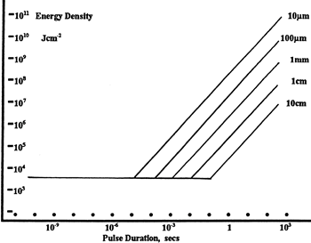
次に、光学素子のLIDTの仕様と最大エネルギ密度を比較しましょう。損傷閾値の測定波長が光学素子に使用する波長と異なっている場合には、その損傷閾値は適宜補正が必要です[3]。経験則から、損傷閾値は波長に対して以下のような平方根の関係であるということです。短い波長で使う場合、損傷閾値は低下します(例えば、1064 nmで 1 J/cm2のLIDTならば、532 nmでは0.7 J/cm2と計算されます)。
波長を補正したエネルギ密度を得ました。これを以下のステップで使用します。
ビーム径は損傷閾値を比較する時にも重要です。LIDTがJ/cm2の単位で表される場合、スポットサイズとは無関係になりますが、ビームサイズが大きい場合、LIDTの不一致を引き起こす原因でもある不具合が、より明らかになる傾向があります[4]。ここで示されているデータでは、LIDTの測定には<1 mmのビーム径が用いられています。ビーム径が5 mmよりも大きい場合、前述のようにビームのサイズが大きいほど不具合の影響が大きくなるため、LIDT (J/cm2)はビーム径とは無関係にはなりません。
次に、パルス幅について補正します。パルス幅が長くなるほど、より大きなエネルギに光学素子は耐えることができます。パルス幅が1~100 nsの場合の近似式は以下のようになります。
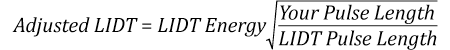
お客様のレーザのパルス幅をもとに、光学素子の補正されたLIDTを計算するのにこの計算式を使います。お客様の最大エネルギ密度が、この補正したエネルギ密度よりも小さい場合、その光学素子はお客様の用途でご使用いただけます。ご注意いただきたい点は、10-9 s と10-7 sの間のパルスにのみこの計算が使えることです。パルス幅が10-7 sと10-4 sの間の場合には、CWのLIDTも調べなければなりません。
当社のウェブ上の損傷閾値の仕様と我々が行った実際の実験の値の間にはある程度の差があります。これはロット間の違いによって発生する誤差を許容するためです。ご要求に応じて、当社では個別のテスト情報やテスト結果の証明書を発行することも可能です。詳細は、当社までお問い合わせください。
[1] R. M. Wood, Optics and Laser Tech. 29, 517 (1998).
[2] Roger M. Wood, Laser-Induced Damage of Optical Materials (Institute of Physics Publishing, Philadelphia, PA, 2003).
[3] C. W. Carr et al., Phys. Rev. Lett. 91, 127402 (2003).
[4] N. Bloembergen, Appl. Opt. 12, 661 (1973).

レーザーシステムが光学素子に損傷を引き起こすかどうか判断するプロセスを説明するために、レーザによって引き起こされる損傷閾値(LIDT)の計算例をいくつかご紹介します。同様の計算を実行したい場合には、右のボタンをクリックしてください。計算ができるスプレッドシートをダウンロードいただけます。ご使用の際には光学素子のLIDTの値と、レーザーシステムの関連パラメータを緑の枠内に入力してください。スプレッドシートでCWならびにパルスの線形パワー密度、ならびにパルスのエネルギ密度を計算できます。これらの値はスケーリング則に基づいて、光学素子のLIDTの調整スケール値を計算するのに用いられます。計算式はガウシアンビームのプロファイルを想定しているため、ほかのビーム形状(均一ビームなど)には補正係数を導入する必要があります。 LIDTのスケーリング則は経験則に基づいていますので、確度は保証されません。なお、光学素子やコーティングに吸収があると、スペクトル領域によってLIDTが著しく低くなる場合があります。LIDTはパルス幅が1ナノ秒(ns)未満の超短パルスには有効ではありません。
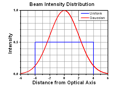
Figure 71A ガウシアンビームの最大強度は均一ビームの約2倍です。
CWレーザの例
波長1319 nm、ビーム径(1/e2)10 mm、パワー0.5 Wのガウシアンビームを生成するCWレーザーシステム想定します。このビームの平均線形パワー密度は、全パワーをビーム径で単純に割ると0.5 W/cmとなります。
しかし、ガウシアンビームの最大パワー密度は均一ビームの約2倍です(Figure 71A参照)。従って、システムのより正確な最大線形パワー密度は1 W/cmとなります。
アクロマティック複レンズAC127-030-CのCW LIDTは、1550 nmでテストされて350 W/cmとされています。CWの損傷閾値は通常レーザ光源の波長に直接スケーリングするため、LIDTの調整値は以下のように求められます。
LIDTの調整値は350 W/cm x (1319 nm / 1550 nm) = 298 W/cmと得られ、計算したレーザーシステムのパワー密度よりも大幅に高いため、この複レンズをこの用途に使用しても安全です。
ナノ秒パルスレーザの例:パルス幅が異なる場合のスケーリング
出力が繰返し周波数10 Hz、波長355 nm、エネルギ1 J、パルス幅2 ns、ビーム径(1/e2)1.9 cmのガウシアンビームであるNd:YAGパルスレーザーシステムを想定します。各パルスの平均エネルギ密度は、パルスエネルギをビームの断面積で割って求めます。
上で説明したように、ガウシアンビームの最大エネルギ密度は平均エネルギ密度の約2倍です。よって、このビームの最大エネルギ密度は約0.7 J/cm2です。
このビームのエネルギ密度を、広帯域誘電体ミラーBB1-E01のLIDT 1 J/cm2、そしてNd:YAGレーザーラインミラーNB1-K08のLIDT 3.5 J/cm2と比較します。LIDTの値は両方とも、波長355 nm、パルス幅10 ns、繰返し周波数10 Hzのレーザで計測しました。従って、より短いパルス幅に対する調整を行う必要があります。 1つ前のタブで説明したようにナノ秒パルスシステムのLIDTは、パルス幅の平方根にスケーリングします:
この調整係数により広帯域誘電体ミラーBB1-E01のLIDTは0.45 J/cm2に、Nd:YAGレーザーラインミラーのLIDTは1.6 J/cm2になり、これらをビームの最大エネルギ密度0.7 J/cm2と比較します。広帯域ミラーはレーザによって損傷を受ける可能性があり、より特化されたレーザーラインミラーがこのシステムには適していることが分かります。
ナノ秒パルスレーザの例:波長が異なる場合のスケーリング
波長1064 nm、繰返し周波数2.5 Hz、パルスエネルギ100 mJ、パルス幅10 ns、ビーム径(1/e2)16 mmのレーザ光を、NDフィルタで減衰させるようなパルスレーザーシステムを想定します。これらの数値からガウシアン出力における最大エネルギ密度は0.1 J/cm2になります。Ø25 mm、OD 1.0の反射型NDフィルタ NDUV10Aの損傷閾値は355 nm、10 nsのパルスにおいて0.05 J/cm2で、同様の吸収型フィルタ NE10Aの損傷閾値は532 nm、10 nsのパルスにおいて10 J/cm2です。1つ前のタブで説明したように光学素子のLIDTは、ナノ秒パルス領域では波長の平方根にスケーリングします。
スケーリングによりLIDTの調整値は反射型フィルタでは0.08 J/cm2、吸収型フィルタでは14 J/cm2となります。このケースでは吸収型フィルタが光学損傷を防ぐには適した選択肢となります。
マイクロ秒パルスレーザの例
パルス幅1 µs、パルスエネルギ150 µJ、繰返し周波数50 kHzで、結果的にデューティーサイクルが5%になるレーザーシステムについて考えてみます。このシステムはCWとパルスレーザの間の領域にあり、どちらのメカニズムでも光学素子に損傷を招く可能性があります。レーザーシステムの安全な動作のためにはCWとパルス両方のLIDTをレーザーシステムの特性と比較する必要があります。
この比較的長いパルス幅のレーザが、波長980 nm、ビーム径(1/e2)12.7 mmのガウシアンビームであった場合、線形パワー密度は5.9 W/cm、1パルスのエネルギ密度は1.2 x 10-4 J/cm2となります。これをポリマーゼロオーダ1/4波長板WPQ10E-980のLIDTと比較してみます。CW放射に対するLIDTは810 nmで5 W/cm、10 nsパルスのLIDTは810 nmで5 J/cm2です。前述同様、光学素子のCW LIDTはレーザ波長と線形にスケーリングするので、CWの調整値は980 nmで6 W/cmとなります。一方でパルスのLIDTはレーザ波長の平方根とパルス幅の平方根にスケーリングしますので、1 µsパルスの980 nmでの調整値は55 J/cm2です。光学素子のパルスのLIDTはパルスレーザのエネルギ密度よりはるかに大きいので、個々のパルスが波長板を損傷することはありません。しかしレーザの平均線形パワー密度が大きいため、高出力CWビームのように光学素子に熱的損傷を引き起こす可能性があります。
ハードコーティングフィルタの利点
ソフトコーティングフィルタの構造
 Click to Enlarge
Figure 24A ソフトコーティングフィルタは、基板層に挟まれた誘電体多層膜を利用します。この図に示されている層の数は実際のバンドパスフィルタにおける層の数を表すものではなく、また縦横比も実際とは異なります。
ハードコーティングフィルタの構造
 Click to Enlarge
Figure 24B ハードコーティングフィルタでは、蒸着は基板表面に施されます。この図に示されている層の数は実際のハードコーティングバンドパスフィルタにおける層の数を表すものではありません。この図面の縦横比も実際とは異なります。
ソフトコーティングとハードコーティングのフィルタは、光学製品として一般的に販売されています。 ソフトコーティングフィルタは、化学的に反応しやすい層の積層構造になっているため、温度安定性が低い、透過率が低い、光散乱が大きい、保存寿命が短いといった問題があります。ハードコーティングフィルタは、高エネルギースパッタリング技術によって光学基板上に化学的に不活性な層を形成するため、そのような欠点がありません。
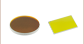
ソフトコーティングフィルタは、Figure 24Aに示すように、マウント内の光学基板間に挟まれた誘電体層で構成されています。誘電体層は、しばしば硫化亜鉛、氷晶石、銀などの壊れやすい材料で構成されています。これらの化学物質は水と反応してフィルタの性能を劣化させるため、湿度の高い環境でのソフトコーティングフィルタの保存寿命は大幅に短くなります。アセンブリの密封部分は環境、取り扱い方、フィルタの組立工程の品質などにより、いずれは機能しなくなり、それに伴って光学性能は急速に低下します。これらの要因により、ソフトコーティングフィルタの寿命は、研究室環境では通常1年から5年です。
ソフトコーティングフィルタが積層構造を有するということは、温度変化がフィルタの光学性能に重大な影響を及ぼすことを意味します。誘電体多層膜、エポキシ、光学基板、吸収ガラス、マウントの熱膨張係数は、一般にはすべて異なるでしょう。その結果、温度変化によってフィルタの形状が予想外に変化することがあります。
ハードコーティングフィルタでは、ガラス基板上に誘電体層をスパッタリングによって作成します。この誘電体多層膜にはソフトコーティングフィルタに使用される材料よりも環境に対して安定な材料が使用されるため、Figure 24Bに示すように性能を低下させることなく環境にさらすことができます。ハードコーティングフィルタはソフトコーティングフィルタよりも薄いため、スペースが限られた用途でも容易に組み込むことができます。スパッタリング工程は自動化されており、再現性が高く、コーティングされていない光学部品に近い透過波面誤差が得られます。
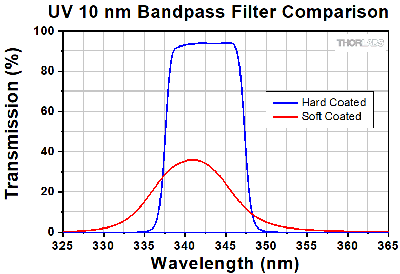
ソフトコーティングフィルタの可視(VIS)波長域での透過率は、銀を使用しない場合で約80%、誘電体多層膜に銀を使用した場合は約50%に制限され、紫外域の透過率はさらに制限されます。Figure 24CとFigure 24Dに示すように、ハードコーティングフィルタでは紫外(UV)域および可視(VIS)域での透過率が向上します。ハードコーティングフィルタのカットオンとカットオフの傾斜は、ソフトコーティングフィルタに比べて急峻です。またハードコーティングフィルタの透過率はソフトコーティングフィルタに比べて平坦です。これは、より複雑なキャビティーフィルタを高い精度と再現性で蒸着できるスパッタリング工程を使用しているためです。
 Click to Enlarge
Figure 24D ハードコーティングフィルタとソフトコーティングフィルタのUV域での性能比較
 Click to Enlarge
Figure 24C ハードコーティングフィルタとソフトコーティングフィルタの可視域での性能比較
| Posted Comments: | |
Maria D
(posted 2025-04-29 08:29:24.127) Hello, for the shortpass filter FESH1000 I only see listed the damage threshold in J/cm2 for pulsed lasers use. Is it possible to use it for a continuous wave application at 1550nm, and if so, what is the damage threshold in this configuration?
Thanks cdolbashian
(posted 2025-05-01 11:56:56.0) Thank you for reaching out to us with this inquiry. Unfortunately, we do not have official damage threshold data for these filters. Do you think you could share a bit about your intended light source to be used, including the power and beam diameter? Sometimes we are able to confirm compatibility based on our own usage of the part and anecdotal customer experiences. I have contacted you directly to discuss this further. Manoj K
(posted 2025-04-16 07:35:27.823) Dear Thorlabs,
Does FELH0400 has autofluorescence under UV (365 nm) exposure? Thanks EGies
(posted 2025-04-18 05:09:29.0) Thank you for contacting Thorlabs. We have not specifically tested if the FELH0400 exhibits autofluorescence under UV exposure. I have reached out to you directly regarding your particular application. Ulrich Leischner
(posted 2025-03-25 16:07:02.757) Hello
we would need a longpass-filter at 45° for cut-on-wavelength of 1560nm. do you know the transmission data for this filter at 45°? Do you know how other filter ( especially FBH1550-40) behaves at 45°?
Greetings
Uli blarowe
(posted 2025-03-26 09:28:08.0) Thank you for contacting Thorlabs. I've reached out to you directly with data at different AOIs for these filters. For any data not listed on the website, feel free to reach out to techsupport@thorlabs.com Christian Marois
(posted 2024-12-06 15:48:03.287) We are interested in using this filter (FELH0900) as a dichroic to reflect the visible light and transmit the infrared. We are assuming, since this is an interference filter, that everything that is blocked is reflected?
Thx blarowe
(posted 2024-12-09 03:32:56.0) Thank you for contacting Thorlabs. These filters will typically reflect a large portion of the blocked light, though we do not spec these for reflectance, so we cannot guarantee any specific values. We do also have dedicated dichroic filters available, such as the DMLP900. I have reached out to you directly with more details. Ivan S
(posted 2024-10-30 08:13:49.477) Hi, I was wondering about the GDD behaviour of this filter, can I assume its dispersion to be roughly similar to 2 mm of fused silica (substrate thickness) when used in transmission? How much GDD do the dielectric stacks add around 2000 nm wavelength? blarowe
(posted 2024-11-01 02:14:36.0) Thank you for contacting Thorlabs. I've reached out to you directly to discuss this. Additional data and specifications can be requested by reaching out to us at techsupport@thorlabs.com Thinh Tran
(posted 2024-08-09 18:09:23.373) Can we use solvents like acetone or IPA to clean these filters? Thanks cdolbashian
(posted 2024-08-14 11:47:28.0) Thank you for reaching out to us with this inquiry. I would recommend following our guidelines outlined on our cleaning page here: https://www.thorlabs.com/newgrouppage9.cfm?objectgroup_id=9025 N C
(posted 2024-05-21 23:58:21.047) Hi
Do U have a low pass filter for 532 nm
thanks (I like it to reflect 532nm and pass 540nm )
thanks cdolbashian
(posted 2024-05-24 10:38:36.0) Thank you for reaching out to us with this inquiry. You can adjust the center wavelength of filter-optics like this by changing the AOI of your light incident on the surface. I would try the 550nm filter and add a few degrees of tilt to it in order to achieve the pass-band you desire. Andreas Baltzer Skov
(posted 2024-05-03 07:38:17.62) Hi - As already stated in a bunch of the comments, increasing the AOI of the various FELH filters blue-shifts the cut-off wavelength. I am curious as to why this is the case though. The filters are obviously more complex than a simple quarter-wave stack, yet I would assume that as you turn the mirrors, the distance between the dielectric layers increases, thus also increasing the wavelength for which the bragg-condition is satisfied. In other words, I would expect the cut-off wavelength to red-shift.
Could you provide some insight as to why we see a blue-shift instead of a red-shift?
Thanks in advance
- Andreas cdolbashian
(posted 2024-05-24 10:14:04.0) Thank you for reaching out to us with this inquiry. This model can be reduced to interference between light reflecting from the front surface of the optic and from light reflected from the interference layers of the optic. Starting as a normal incidence (0° AOI) and increasing the OPL, we will find that the Optical Path Length (OPL) increases for both rays: the one reflecting in air, and the one reflecting within the dielectric layers. However, the key point here is that while both of them are increasing, the difference between them (OPD) is actually decreasing, with the OPL in Air (from the front surface), increasing at a slightly faster rate than the one through the material. As this is the case, the wavelength shift is a blue shift. Additionally, for filter-like optics which are designed to be used at 45° (such as a dichroic mirror), tilting toward larger angles will blueshift your spectrum, while tilting toward normal incidence will redshift your spectrum. I have contacted you directly with some helpful reference documentation. user
(posted 2024-01-22 10:22:05.787) Could you tell me the approximate thickness of the dielectric coating? Thanks. jpolaris
(posted 2024-01-24 01:15:15.0) Thank you for contacting Thorlabs. Unfortunately, the dielectric coating thickness of these hard-coated edgepass filters is information that we consider to be proprietary. user
(posted 2023-09-14 11:55:16.38) Hey! Do you have any option on higher shortpass filters?
Like 1600nm shortpass or even 1700nmshortpass?
Thank you jpolaris
(posted 2023-09-14 08:09:16.0) Thank you for contacting Thorlabs. At the present moment, we do not have any stock shortpass filters with cutoff wavelengths above 1500 nm. I have reached out to you directly to discuss alternative solutions. Requests for custom optics can be made by emailing us at techsupport@thorlabs.com. Bruce Tiemann
(posted 2023-09-12 11:29:56.69) You already offer downloadable data containing the spectral data for each part. However, it would be super useful to offer a spreadsheet containing the spectral data for all the parts in one giant spreadsheet, such that we don't have to do separate downloads for each individual item.
I am writing this feedback on one of your dielectric edge filters pages, but this comment could equally apply to other filters, including color glass filters, shortpass, longpass, notch and bandpass, as well as substrate transmission spectra, AR coating data, and also mirror and beamsplitter coating spectra.
Maybe a few giant spreadsheets (substrates, color glass, coatings) or something, but, rather than hundreds of different individual optics or coatings.
Thanks! cdolbashian
(posted 2023-09-25 10:46:23.0) Thank you for the suggestion! I have passed this along internally as a potential way in which we can share our test data in a more concise way. If you ever need data which you do not see on the web, please feel free to contact us at Techsupport@thorlabs.com. J. Freitag
(posted 2023-08-03 09:27:00.363) Dear Thorlabs,
If available I would be pleased if you could provide the transmission and reflectance data of the FELH0500 filter at 45 deg AOI to us. Thank you a lot, J. Freitag cdolbashian
(posted 2023-08-10 02:07:38.0) Thank you for reaching out to us with this inquiry. I have contacted you directly with such data. For future inquiries like this, please feel free to reach out to tech support at Techsupport@thorlabs.com. Poul Petersen
(posted 2023-07-04 14:30:46.44) Dear Thorlabs
I am interested in a buying a set of custom sizes of your FELH0600 and FELH0700 filters. The filters should be 46.1 mm in diameter. The thickness is less important. we would be interested in 5-10 filters of each kind (600 and 700 nm shortpass). Would you be able to provide a custom filter size?
thank you
Poul Petersen cdolbashian
(posted 2023-07-21 03:00:51.0) Thank you for reaching out to us with this inquiry. We can very likely fulfill this for you as a custom. I have put you in contact with your local technical sales team. For future requests, please feel free to find the contact information for your closest thorlabs office, and reach out to them directly via email: https://www.thorlabs.com/locations.cfm Michele Cotrufo
(posted 2023-04-08 12:07:33.17) Can you clarify how you calculate the optical density? I am looking at the specs of the FESH1000, inside the file FESH1000_OD.xlsx file.
At a wavelength = 1500nm, the quoted OD is 6.98.
However, in the same file it is mentioned that the transmission at 1500nm is T = 0.00039%. But then OD = - log10(T/100) = 5.4. It differs by more than one order of magnitude. Which values should I trust? cdolbashian
(posted 2023-04-13 11:07:26.0) Thank you for reaching out to us Michele. At the time of posting this, we are looking into the discrepancy and presentation of the raw data you are referring to. As a safe bet, I would simply use the minimum guaranteed performance for these products. In this case, the transmission is guaranteed to be >90% in the pass region, while the OD is guaranteed to be >5 in the blocking region. user
(posted 2023-01-26 10:03:52.77) Hello,
At which incidence angle is the transmission specified?
Thanks! jdelia
(posted 2023-01-26 01:15:57.0) Thank you for contacting Thorlabs. The transmission for these filters is specified at 0 degrees AOI. Martin Nielsen
(posted 2023-01-03 08:05:13.143) Can you provide information on the dependence on angle of incidence for the FELH0900 and the FELH0850 filter? cdolbashian
(posted 2023-01-10 02:31:20.0) Thank you for reaching out to us Martin! We have not tested all of our filters at all AOI, but as a rule of thumb, a 45 deg AOI blue-shifts the cut-on wavelength by roughly 10% compared to 0 deg AOI. Please note though, that this is quite heavily dependent on the input polarization since these are based on dielectric coatings. The desired steepness of transition is also affected. Ruohong Li
(posted 2022-11-09 13:51:03.59) do you have 2 inch diameter option for FELH0400? Thanks jgreschler
(posted 2022-11-17 02:40:55.0) Thank you for reaching out to Thorlabs. Custom items can be requested by reaching out to techsupport@thorlabs.com. This is a configuration we have quoted in the past, I have reached out to you directly to discuss quantity and begin the quoting process. XINJUN LI
(posted 2022-05-26 12:30:04.72) 1.交货期要多久,有现货供应吗 cdolbashian
(posted 2025-03-20 04:33:20.0) Thank you for reaching out to us with this inquiry. For up-to-date shipping and stock information, please contact your local sales team. I have contacted you directly to facilitate this communication. Thinh Tran
(posted 2022-03-30 08:28:23.917) Hi, It would be nicer if there are a selection of short pass filters for IR range from 1000 to 1500 nm with 50 nm step like long pass filters. jdelia
(posted 2022-03-30 11:05:35.0) Thank you for contacting Thorlabs, and for providing this valuable feedback. I will passing this product line request along to our internal suggestion forum. Markus Stabel
(posted 2021-07-27 14:53:25.533) Hello,
I'm looking for a filter that blocks light at 606nm but transmitts it from 610nm (or slightly above) on. Something like an FELH0610 would fit that description. Is this something you can provide?
Or do you have AOI data for the FELH0650 so that I can check if angling that filter far enough moves the cutoff to where I want it?
Thanks. YLohia
(posted 2021-08-03 02:55:45.0) Hello, thank you for contacting Thorlabs. Unfortunately, we don't have AOI data for the FELH0650. As a rule of thumb, a 45 deg AOI blue-shifts the cut-on wavelength by roughly 10% compared to 0 deg AOI, but this is quite heavily dependent on the input polarization since these are based on dielectric coatings. The desired steepness of transition is also affected. Richard Graham
(posted 2021-07-05 14:12:33.827) I was wondering if you have a specification or rough guideline for the maximum CW power for these premium edge-pass filters (FELH and FESH part prefix); I only see specifications for pulsed power.
I understand there would be a difference depending on the spectra due to the difference between reflection and absorption loss mechanisms. I am wondering if all my power is generally within the design range given on the spectra plots, can I assume that the losses will be primarily in reflection, and thus the CW power limit very high? I am wanting to confirm if something on the order of 100 W/cm^2, up to 5W total would be OK.
Thanks. YLohia
(posted 2021-07-12 10:46:41.0) Hello, thank you for contacting Thorlabs. The damage threshold data are listed in the “Damage Threshold” tab for a few of the filters on this page. Unfortunately we do not test every single filter yet but you can use this table for a general guideline on how a filter would perform for different wavelength and pulse length. That being said, given that your power level is 5 W for a 2.5 mm at IR wavelengths (not UV), we would expect your FESH0950 to be fine. Julien Camard
(posted 2021-05-27 11:19:42.53) Hello, I was wondering if these filters have to be used at 90 degrees with respect to the beam direction or if they can be tilted? Thanks! YLohia
(posted 2021-05-27 02:39:10.0) Hello, these filters are designed to be used at 0 degree AOI (normal incidence) and that is the angle the cut-off wavelength is specified for. For any other AOIs, the cut-off wavelength will be blue-shifted. For angle-specific data, please email your local Thorlabs Tech Support team. user
(posted 2021-04-16 18:26:55.303) Hello, in the documentation the Diameter is 25mm with ring and clear aperture diameter is 21.1mm. can you give me the diameter about only the filter without ring? Many thanks YLohia
(posted 2021-04-21 11:51:57.0) Hello, these filters have a 23.3 mm diameter unmounted. user
(posted 2021-04-08 09:29:20.363) Hello, in the documentation the thickness of the filter is quoted as 3.5mm, but that seems to be for the mount. Could you confirm the thickness of just the filter (for optical path length calculations). Many thanks. YLohia
(posted 2021-04-08 11:14:59.0) Hello, thank you for contacting Thorlabs. The thickness of the unmounted optic for these premium hard coated filters is listed on the "Specs" tab as 2 mm. user
(posted 2021-01-14 11:21:38.017) Is it possible to purchase this filter in other sizes? e.g 1.5" or 2.0"? YLohia
(posted 2021-01-14 02:47:13.0) Hello. Custom Edgepass Filter Sizes are available by contacting Tech Support (techsupport@thorlabs.com). We will discuss this directly. user
(posted 2021-01-04 11:59:54.013) Could I know the reflection wavefront distortion on this filter? I'm more caring of reflection quality. Also, could you please provide the angle tolerance data? Consider I may have a incident angle control error up to 5degeree. YLohia
(posted 2021-01-12 02:23:06.0) Thank you for contacting Thorlabs. The FELH0500 filter should have a reflected wavefront error of around 1 wave (estimate), but please note that this can vary between units since this is not a controlled/measured spec. We will reach out to you directly with AOI data. Feng Jin
(posted 2020-10-13 13:10:39.333) How the OD changes versus the incident angle of input light? Do you have a graph for it? YLohia
(posted 2020-10-13 03:22:27.0) Thank you for contacting Thorlabs. I have reached out to you directly with some data. dallas strandell
(posted 2020-09-30 12:51:15.79) Hi,
The specs for the 500nm longpass say the Transmission
Region (T>90%) starts at 508 nm. However the typical data in the excel says the 90% region starts at 500 nm. Which is correct? Thanks YLohia
(posted 2020-10-01 04:02:36.0) Hello, thank you for contacting Thorlabs. The excel file contains typical data, which means that the information on it is taken only from one measurement and can vary between production lots. We formally only guarantee 90% transmission at 508 nm. Please note that the cut-on wavelength can shift to the lower end of the spectrum as a function of AOI. Ke Wang
(posted 2020-01-12 08:47:32.42) Could you pls make High-Performance longpass Filters cutting on between 1600 nm and 1800 nm? YLohia
(posted 2020-01-13 10:12:51.0) Hello, thank you for your suggestion. I have posted your request to our internal engineering forum for consideration of these 1600 nm - 1800 nm longpass filters as future products. TRAIAN MIU
(posted 2019-09-13 15:29:24.063) Is this filter available in a 80 mm diameter as well? nbayconich
(posted 2019-09-16 03:54:44.0) Thank you for contacting Thorlabs. We can provide larger versions of these filters as a custom option. I will reach out to you directly with more information about our custom capabilities. akuznetsov
(posted 2018-10-08 12:25:21.68) Please check with production to make sure the direction arrows are clearly marked (engraved). I received a filter than had a line and a tiny dot at the end of a line, it was not clear that the dot represented an arrow, but I assumed as such. I am used to seeing a full length arrow on your filters. YLohia
(posted 2018-10-25 09:50:05.0) Hello, thank you for your feedback. Please accept our apologies for any inconvenience caused by this. We have finished checking our entire component inventory for these filters, but we did not find any engravings where the arrowhead was a different shape or a dot. That being said, our production team has been made aware of this issue to prevent it from happening again. jurkusk
(posted 2018-09-18 12:12:06.95) Hello,
Could you tell me whether these filters work by absorbing or reflecting the wavelengths that are not transmitted? YLohia
(posted 2018-09-19 02:58:27.0) Hello, most of the rejected band is reflected with minimal absorption. Please note that there will be scatter and, unlike a dichroic mirror, we cannot guarantee the usability of the reflected light. carl.asplund
(posted 2018-09-12 10:41:27.77) Hi,
What is the wavelength dependence on incidence angle for FESH900? We have unpolarized light.
I have the same question for FELH900 if you have that data too.
Best regards,
Carl Asplund nbayconich
(posted 2018-09-14 03:29:48.0) Thank you for contacting Thorlabs. Increasing the AOI will shift the cutoff wavelength of these types of edgepass filters towards a shorter wavelength. Generally the cutoff wavelength will decrease as AOI increases.
We have done more extensive transmission testing for our bandpass and notch pass filters as a function of wavelength. Our webpage located in the link below for our notch filters has an equation that shows how to calculate the passing centerwavelength shift of an interference filter as a function of AOI. A similar effect can be seen for the cutoff wavelength of the edgepass filters.
https://www.thorlabs.com/newgrouppage9.cfm?objectgroup_id=3880#D067E48C-DAAE-4C54-B614-CDDA86B81DF9-3880
I will contact you directly with more information. tug13936
(posted 2018-04-23 18:45:50.27) Can you provide the transmission curve for thsese filters (FELH0700 or FELH0600) with s-polarization and p-polarization? Is there any difference when the polarization is different? nbayconich
(posted 2018-04-27 05:38:57.0) Thank you for your feedback. The Transmission of S & P polarization at an angle of incidence of zero degrees will be the same. At 0 degrees AOI, s and p do not exist and you will see an identical response at 0 degrees AOI to vertical and horizontal polarization. If you are interested in a particular angle of incidence we can provide a scan service for our products. I will contact you directly with more information. mountainskysea
(posted 2017-11-01 17:17:51.043) 问下FL和FB开头的filter有什么区别? tfrisch
(posted 2017-12-13 02:23:48.0) Hello, thank you for contacting Thorlabs. FB nominally stands for Filter-Bandpass, and FL nominally stands for Filter-Laser, though both are bandpass filters. Generally, an FL filter will have a higher peak transmission than an FB with a similar bandwidth. Tao.Jiang
(posted 2017-02-03 16:31:57.723) Dear Thorlabs Team, is it possible to manufacture short pass filter of FESH1100, similar to FESH1000? tfrisch
(posted 2017-02-13 02:12:05.0) Hello, thank you for contacting Thorlabs. It looks like you are already in contact with our Technical Support team on this matter, but I will also post this idea in our internal engineering forum. nejbauer
(posted 2016-10-04 09:25:09.31) Do you know the GVD (group velocity dispersion) for these filters? Or any similar data relevant to femtosecond applications?
Specifically, I interested about GVD for the region 1200-1600 nm in transmission for FELH1100. jlow
(posted 2016-10-10 11:07:36.0) Response from Jeremy at Thorlabs: Unfortunately we do not have GVD data for these filters. daniel.brunner
(posted 2016-02-10 11:13:06.78) Are these filter absorptive or reflective outside of their transmission window? besembeson
(posted 2016-02-11 09:37:17.0) Response from Bweh at Thorlabs USA: Whether it is absorptive or reflective depends on the wavelengths you are looking at. These filters are hard-coated so the blocking band is reflective. Very far away from the design window, some absorption does start to show up. jay.mathews
(posted 2015-09-13 18:54:43.43) It would be nice if you made a longpass filter that would block 1550 nm and let longer wavelengths through. Maybe 1575 or 1600 nm cutoff? 1550 lasers are cheap now, so people are using them as pumping sources for all kinds of spectroscopy and other optical experiments. We need a way to filter out the 1550. besembeson
(posted 2015-09-29 12:11:52.0) Response from Bweh at Thorlabs USA: Thanks for the feedback. We will look into offering this in the future. jorpet
(posted 2015-04-26 09:25:49.19) A long and short pass pair of FELH and FESH at 1050 nm will be very useful for me (and I suppose to many others). It will make a very good blocker/selector for 1064 nm. If one adds FELH 1100 (ore even FELH 1090) it makes a selection of three filters very useful for 1064 nm laser applications. besembeson
(posted 2015-08-28 09:41:30.0) Response from Bweh at Thorlabs USA: We also provide 1064nm bandpass filters with different FWHM values depending on user applications, for example FLH1064-8 or FL1064-10 or the FL1064-3. But in some cases, you can do multiple combinations like you suggested. As these will be so application dependent, it seems easier to make a shortpass-longpass combination as suitable. user
(posted 2014-12-02 10:14:41.57) Do you offer custom wavelength with small amount? or you offer custom wavelength for OEM? cdaly
(posted 2014-12-04 04:22:48.0) Response from Chris at Thorlabs: This may be more feasible at larger OEM quantities, but it would still typically be on a case to case basis. We would be happy to discuss the possibility of smaller quantities as well. Please contact us with your requirements at techsupport@thorlabs.com to discuss this further. aklossek
(posted 2014-07-10 01:46:49.007) Dear ladies and gentlemen,
I would like to know how sensitive are these filters to changes of the incident angle? It is written that the cut-off wavelength shifts of about 10 % between 0° and 45° in case of the standard filters. This would be a shift to 900 nm for the 1000 nm SP. This is enourmous.
Best regards
André Klossek jlow
(posted 2014-07-14 10:41:59.0) Response from Jeremy at Thorlabs: These are dielectric filters and they would be very sensitive to angle of incidence (AOI) change. These are designed for use at 0° AOI. If you require something at 45°, then your application would probably benefit from using other types of filters/mirrors instead. We will contact you directly to discuss about this and come up with a solution. mibr
(posted 2014-02-25 11:51:26.753) Why do Thorlabs not specify the power threshold on your filters? Can they be used with pulsed lasers? jlow
(posted 2014-02-27 03:05:01.0) Response from Jeremy at Thorlabs: The damage threshold data are listed in the “Damage Threshold” tab for a few of the filters on this page. Unfortunately we do not test every single filter yet but you can use this table for a general guideline on how a filter would perform for different wavelength and pulse length. nico.krauss
(posted 2013-11-28 14:19:49.62) I am looking for a premium bandpass filter at 820 nm with a bandwidth of 10 nm. Is it possible to shift the center wavelength of the FBH810-10 to 820nm by rotating? If yes, what kind of losses do I have to expect? Are there any other possible solutions to this problem? tcohen
(posted 2013-12-05 02:59:17.0) Response from Tim at Thorlabs: Thanks for contacting us. Actually, it is possible to change the center wavelength by angle of incidence tuning, but typically as you increase the angle of incidence, the center wavelength goes down. We’ll work on adding some datapoints describing this to our presentation. Although the quality of the premium bandpass filters are higher (transmission, out of band OD, surface quality, etc.), we do offer this as a stock option in our economy line: FB820-10. I’ll contact you to discuss this further. parkse
(posted 2013-09-23 09:13:22.927) Please introduce hard-coated premium shortpass filter for cut-off wavelength of 800 nm which will be used for transimssion of 780 nm (RB) and blocking of 852 nm (Cs) light. cdaly
(posted 2013-09-26 15:09:00.0) Response from Chris at Thorlabs: Thank you for your suggestions. It may be possible to provide a custom filter with this cut-on, but the price would likely increase significantly. Are you able to use a dichroic short pass filter in your application? the DMSP805, when used at 45 degree angle of incidence, has a high transmission at 780, with a high reflectance 852nm, found here: http://www.thorlabs.com/newgrouppage9.cfm?objectgroup_id=3313&pn=DMSP805#5306 lpeterso987
(posted 2013-08-16 12:39:16.687) Your FEL1400 may meet our needs but the FEHL would be better since the transmission is near 100% rather than 80% for the FEL. Is it possible to get the FEHL with a 1400nm cuton?
Also, can you tell me the power handling capabilities of the FEL1400 (or the FEHL). Will it be ok to filter 50 W of laser light? pbui
(posted 2013-08-22 16:09:00.0) Response from Phong at Thorlabs: Thank you for your post. Such a customization would require a custom coating. As for the damage threshold, we do not have a spec for our longpass filters. Our filters may have multiple transmitting and blocking regions. Depending on whether or not the power is concentrated on the transmitted or blocking region, the amount of power will be absorbed by the filter will vary, which will cause the damage threshold to vary as well. We will contact you directly to discuss this within the specifics of your application and to see about the possibility of offering a custom longpass filter. florian.auras
(posted 2013-05-31 12:26:25.94) Dear Thorlabs Team,
these filters have proven to be extremely useful in several of our setups. Would it be possible to extend the portfolio to shorter wavelength regions? A 400 nm or 365 nm filter of this type would be fantastic! Thanks tcohen
(posted 2013-06-06 12:02:00.0) Response from Tim at Thorlabs: Thank you for your suggestion. We are constantly growing our selection and are looking to expand our IBS capabilities to further this line. jlow
(posted 2013-01-21 16:18:00.0) Response from Jeremy at Thorlabs: We can do this for larger diameters. I will get in contact with you directly to discuss about this. roumis.d
(posted 2013-01-21 12:07:06.12) Is there any chance of these lp filters being available in larger diameters.. 50mm would be quite helpful.
Thanks |
| Item # | Cut-On Wavelength | Transmission Dataa | Damage Thresholdb |
|---|---|---|---|
| FELH1000 | 1000 nm | 3.75 J/cm2 (1064 nm, 10 ns, 10 Hz, Ø0.516 mm) | |
| FELH1050 | 1050 nm | 0.1 J/cm2 (532 nm, 10 ns, 10 Hz, Ø0.360 mm) | |
| FELH1100 | 1100 nm | - | |
| FELH1150 | 1150 nm | - | |
| FELH1200 | 1200 nm | - | |
| FELH1250 | 1250 nm | - | |
| FELH1300 | 1300 nm | - | |
| FELH1350 | 1350 nm | - | |
| FELH1400 | 1400 nm | - | |
| FELH1450 | 1450 nm | - | |
| FELH1500 | 1500 nm | - |
| Item # | Cut-On Wavelength | Transmission Dataa | Damage Thresholdb |
|---|---|---|---|
| FELH0400 | 400 nm | - | |
| FELH0450 | 450 nm | - | |
| FELH0500 | 500 nm | - | |
| FELH0550 | 550 nm | 1.0 J/cm2 (532 nm, 10 ns, 10 Hz, Ø0.472 mm) | |
| FELH0600 | 600 nm | - | |
| FELH0650 | 650 nm | - | |
| FELH0700 | 700 nm | - | |
| FELH0750 | 750 nm | - | |
| FELH0800 | 800 nm | - | |
| FELH0850 | 850 nm | - | |
| FELH0900 | 900 nm | - | |
| FELH0950 | 950 nm | 0.25 J/cm2 (1064 nm, 10 ns, 10 Hz, Ø1.010 mm) |
-
 をクリックすると、プロット図やダウンロード可能なデータをご覧いただけます。ここに記載されているデータは典型値であって、ロット毎に性能のバラツキが生じる可能性がある点にご注意ください。この傾向はフィルタで指定されている波長範囲以外で特に顕著となります。
 - 「損傷閾値」タブでは、レーザ損傷閾値がどのように測定され、使用する用途に適切な光学素子の決定にその値をどのようにご利用いただけるかを詳しくご覧いただけます。
| Item # | Cut-Off Wavelength | Transmission Dataa | Damage Thresholdb |
|---|---|---|---|
| FESH0450 | 450 nm | - | |
| FESH0500 | 500 nm | - | |
| FESH0550 | 550 nm | - | |
| FESH0600 | 600 nm | 3 J/cm2 (1064 nm, 10 ns, 10 Hz, Ø0.429 mm) | |
| FESH0650 | 650 nm | - | |
| FESH0700 | 700 nm | 1.0 J/cm2 (532 nm, 10 ns, 10 Hz, Ø0.472 mm) |
| Item # | Cut-Off Wavelength | Transmission Dataa | Damage Thresholdb |
|---|---|---|---|
| FESH0750 | 750 nm | - | |
| FESH0800 | 800 nm | - | |
| FESH0850 | 850 nm | - | |
| FESH0900 | 900 nm | - | |
| FESH0950 | 950 nm | - | |
| FESH1000 | 1000 nm | 7.5 J/cm2 (1064 nm, 10 ns, 10 Hz, Ø0.516 mm) |
- をクリックすると、プロット図やダウンロード可能なデータをご覧いただけます。ここに記載されているデータは典型値であって、ロット毎に性能のバラツキが生じる可能性がある点にご注意ください。この傾向はフィルタで指定されている波長範囲以外で特に顕著となります。
- 「損傷閾値」タブでは、レーザ損傷閾値がどのように測定され、使用する用途に適切な光学素子の決定にその値をどのようにご利用いただけるかを詳しくご覧いただけます。
こちらのハードコーティングロングパスフィルターキットには、Ø25.0 mmマウント付きロングパスフィルタが10個入っています。フィルタの筐体には型番と光の透過方向を示す矢印が刻印されています。フィルタは、整理用および物理的衝撃からの保護用としてご利用いただける保管ケースに入っています。下の表は各キットに含まれるフィルタを記載しています。
| Kit Item # | Included Filter Item # | Cut-On Wavelength | Transmission/ OD Dataa | Included Filter Item # | Cut-On Wavelength | Transmission/ OD Dataa |
|---|---|---|---|---|---|---|
| FKLPVIS | FELH0500 | 500 nm | FELH0750 | 750 nm | ||
| FELH0550 | 550 nm | FELH0800 | 800 nm | |||
| FELH0600 | 600 nm | FELH0850 | 850 nm | |||
| FELH0650 | 650 nm | FELH0900 | 900 nm | |||
| FELH0700 | 700 nm | FELH0950 | 950 nm | |||
| FKLPIR | FELH1000 | 1000 nm | FELH1250 | 1250 nm | ||
| FELH1050 | 1050 nm | FELH1300 | 1300 nm | |||
| FELH1100 | 1100 nm | FELH1350 | 1350 nm | |||
| FELH1150 | 1150 nm | FELH1400 | 1400 nm | |||
| FELH1200 | 1200 nm | FELH1500 | 1500 nm |
- をクリックすると、グラフやデータ(ダウンロード可能)がご覧いただけます。グラフの網掛け部分は、これらのフィルタをご使用になる際に推奨する波長範囲を示しています。ここに記載されているデータは典型値であり、性能はロット毎に異なる可能性があります。その傾向はグラフの網掛け部分以外で特に顕著となりますのでご注意ください。
こちらのハードコーティングショートパスフィルターキットには、Ø25.0 mmマウント付きショートパスフィルタが10個入っています。フィルタの筐体には型番と光の透過方向を示す矢印が刻印されています。フィルタは、整理用および物理的衝撃からの保護用としてご利用いただける保管ケースに入っています。下の表は各キットに含まれるフィルタを記載しています。
| Kit Item # | Filter Included | Cut-Off Wavelength | Transmission/ OD Dataa | Filter Included | Cut-Off Wavelength | Transmission/ OD Dataa |
|---|---|---|---|---|---|---|
| FKSPVIS | FESH0450 | 450 nm | FESH0700 | 700 nm | ||
| FESH0500 | 500 nm | FESH0750 | 750 nm | |||
| FESH0550 | 550 nm | FESH0800 | 800 nm | |||
| FESH0600 | 600 nm | FESH0900 | 900 nm | |||
| FESH0650 | 650 nm | FESH1000 | 1000 nm |
- をクリックすると、グラフやデータ(ダウンロード可能)がご覧いただけます。グラフの網掛け部分は、これらのフィルタをご使用になる際に推奨する波長範囲を示しています。ここに記載されているデータは典型値であり、性能はロット毎に異なる可能性があります。その傾向はグラフの網掛け部分以外で特に顕著となりますのでご注意ください。