 Products Home / 自動(電動)ステージ / 電動回転ステージ・マウント / SM2-Threaded Rotation Mount with Resonant Piezoelectric Motors
SM2-Threaded Rotation Mount with Resonant Piezoelectric Motors

- SM2-Threaded Rotation Mount with Closed-Loop Positioning
- Open Frame Design for OEM Applications
- Control via Interface Board, GUI, or ASCII Message Calls
- Fully Integrated Drive Electronics
Application Idea
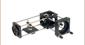
The ELL21K rotates a mounted, SM2-threaded waveplate within a 60 mm cage assembly.
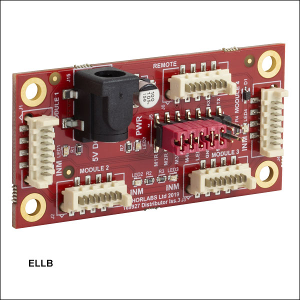
ELLB
Bus Distributor
Interface Board
ELL21K
Rotation Mount
Bundle
(Mount and Board Included)
Rotation Mount for Ø2" or Ø50.0 mm Optics
(Also Available Individually)


Please Wait
| Key Specificationsa | |
|---|---|
| Travel (No Limit Switches)b |
360° Continuous |
| Bidirectional Repeatabilityc | 0.05° (0.87 mrad) |
| Bidirectional Accuracyd | 0.035° (0.61 mrad) |
| Axis Wobblee | 0.032° (0.56 mrad) |
| Max Speedf | 260°/s |
| Max Loadg | Vertical: 100 g (3.5 oz) Horizontal: 300 g (10.6 oz) |
| DC Voltage Input | 4.5 to 5.5 V |
| Minimum Lifetime | 100 km (>403 000 Revolutions) |
| Mount Dimensions |
92.0 x 115.0 x 21.0 mm (3.62" x 4.53" x 0.83") |
| Mount Weight | 260 g (9.2 oz) |
 Thorlabs' Elliptec Technology for OEM
Click to Enlarge
Figure 1.1 ELL21 Mount with ELLA6 Grooved Adapter Plate
Features
- SM2-Threaded Rotation Mount for Ø2" or Ø50 mm Optics
- Ideal for OEMs and Applications Requiring Rapid and Precise Optic Rotation
- Micro-B USB and Picoflex®1 Connectors for Control Signals
- Multi-Drop Serial Communication Protocol Supported
- Absolute Magnetic Encoder Used to Position Mount (Ideal for Light Sensitive Applications)
- Bus Distributor Facilitates Control of up to Four Elliptec® Devices
- Moving World Adapters Attach Using M3 x 0.5 Taps for Additional Mounting Features:
- ELLA6(/M) Adapter with Keyway for Fiber Alignment Accessories
- ELLA7(/M) Adapter with SM1 Threads and Taps for 30 mm Cage Systems
- ELLA8 Adapter with Five SM05-Threaded Holes for Mounted Filters/Optics
- ELLC2 Accessory Upgrade Pack Available Below
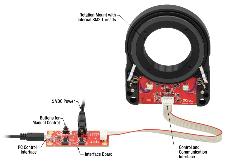
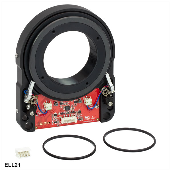
Driven by Thorlabs' Elliptec® piezoelectric resonant motor technology, this rotation mount is designed to be a compact solution for applications requiring optic rotation. The rotation mount is offered as a standalone unit (Item #'s ELL21 and ELL21/M), or as part of a bundle (Item #'s ELL21K and ELL21K/M), which also contains an interface board for manual control of the mount, power supply, and cables for connecting the mount and interface board to each other and to a PC. Thorlabs also offers the ELLC2 Accessory Pack which can be used to upgrade standalone units to kits.
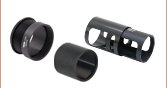
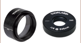
The rotating cell of each mount is internally SM2 (2.035"-40) threaded and includes two SM2RR retaining rings for mounting Ø2" or Ø50 mm optics. It is designed to be lightweight and compact, and the closed-loop operation provides rotation to specified orientations with a repeatability of 0.05°. The assembled components of the ELL21K(/M) bundle are shown in Figure 1.1, with key features labeled. Please see The Elliptec® Motor tab for more information.
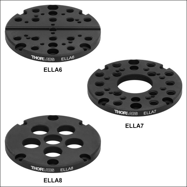
The moving world is also compatible with three adapter plates (sold separately) that offer a variety of mounting threads and bores for other applications. The ELLA6(/M) adapter has an array of mounting holes, 30 mm cage system compatibility, and a keyway for fiber accessories. The ELLA7(/M) adapter has similar mounting holes and cage system compatibility in addition to a central SM1 (1.035"-40) threaded bore. The ELLA8 adapter has five SM05 (0.535"-40) threaded ports for use with mounted filters and other optics, as well as a smooth Ø1/2" central bore.
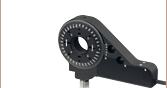
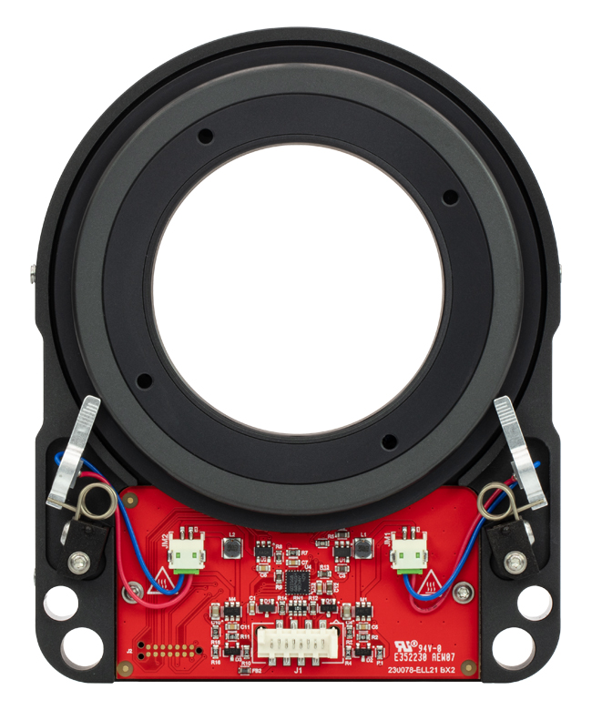
The motors are highly dynamic and have no gearing. The tips of both motor housings are in firm contact with the plastic track at the base of mount, as can be seen in Figure 1.2. The motors are installed with opposite orientations and translation in both directions occurs when one motor pushes the track forward while the other pulls it backward. The rotation mount is not designed for continuous operation. We recommend operation with duty cycles of 40% or less. When power is not applied to the motors, the stage is held in place by an approximately 0.01 N·m combined torque exerted by the stationary arms of the motors.
The open frame format, versatility, and simplicity of this rotation mount makes it attractive for OEM applications, as it can be customized according to customer requirements and produced in high-volume quantities. Please contact us to discuss your specific requirements so that we may tailor a solution to meet the needs of your application.
Control
There are multiple options for powering, driving, and controlling this rotation mount, which are detailed in the Positioning the Rotation Mount section of the Operation tab. The mount possesses a 3.3 V serial bus and is designed to be operated with or without the interface board; the Pin Diagram tab provides pin assignments. Thorlabs offers software for our Elliptec products capable of providing full and independent control of the mount. When the interface board is used as an accessory to change the position of the mount, its status in the software is automatically updated.
Click to Enlarge
Figure 1.2 The components of the ELL21K Rotation Mount Bundle are shown connected and with key features labeled.
Multiple Elliptec devices can be controlled using the ELLB Bus Distributor or by splicing multiple connectors onto one ribbon cable. A single bus distributor can connect up to four Elliptec devices; up to 16 devices can be connected if the buses are daisy chained. This bus can be controlled one of three ways: through an interface board (included with the bundles below) to connect to a PC running the Elliptec software, by connecting to an Arduino®2 or Raspberry Pi®3 board, or by wiring the connector pins to a user-supplied control board. Alternatively, up to 16 devices can be spliced onto a single ribbon cord. The devices can then be simultaneously controlled by the interface board or selectively controlled by the Elliptec software. See the manual for instruction on how to splice multiple devices onto a ribbon cord and the Pin Diagrams tab for pin assignments when making custom connections.
- Picoflex is a registered trademark of Molex Incorporated.
- Arduino is a registered trademark of Arduino Sa Société Anonym (SA).
- Raspberry Pi is a registered trademark of the Raspberry Pi Foundation.
| Elliptec Resonant Motor Products | |||||||
|---|---|---|---|---|---|---|---|
 |
 |
 |
 |
 |
 |
 |
 |
| Multi-Position Sliders |
28 mm Linear Stage |
60 mm Linear Stage |
Rotation Stage |
Ø1/2" Rotation Mount |
Ø1" Rotation Mount |
Ø2" Rotation Mount |
Motorized Iris |
| Specificationsa | |
|---|---|
| Performance | |
| Travel | 360° Continuousb |
| Maximum Speedc | 260°/s |
| Bidirectional Repeatabilityd | 0.05° (0.87 mrad) |
| Bidirectional Accuracye | 0.035° (0.61 mrad) |
| Backlash | 0.018° (0.31 mrad) |
| Encoder Resolution (Absolute Magnetic Encoder) |
65536 counts/rev |
| Minimum Incremental Motion | 0.0055° (96 µrad) |
| Minimum Holding Torque (Both Motors Engaged) |
6.3 cN•m |
| Axis Wobblef | 0.032° (0.56 mrad) |
| Maximum Total Loadg | Vertical: 100 g (3.5 oz) Horizontal: 300 g (10.6 oz) |
| Minimum Lifetimeh | >403 000 Revolutions (100 km) |
| Electrical | |
| Motor Type | Elliptec® Resonant Piezo |
| DC Voltage Input | 4.5 to 5.5 V |
| Typical Current Consumption, During Movement |
800 mA |
| Typical Current Consumption, During Standby |
50 mA |
| Communications | |
| Bus | Multi-Drop 3.3 V/5 V TTL RS232 |
| Connector on Rotation Stage Board | Picoflex® |
| Connectors on Interface Board | Picoflex®, Micro USB, DC Jack [6.3 mm OD (GND), 2.1 mm ID (+5 V)] |
| Speed | 9600 baud |
| Data Length (1 Stop Bit, No Parity) | 8 bit |
| Protocol Data Format | ASCII HEX |
| Module Address and Command Format | Mnemonic Character |
| Mechanical | |
| Mounting Thread | SM2 (2.035"-40) |
| Dimensions of the Rotation Mount Board | 92.0 x 115.0 x 21.0 mm (3.62" x 4.53" x 0.83") |
| Weight of Rotation Mount Board | 260 g (9.2 oz) |
| Environmental Operating Conditions | |
| Temperature Range | 15 to 40 °C (59 to 104 °F) |
| Maximum Relative Humidity (Non-Condensing) |
<80% at 31 °C |
Click to Enlarge
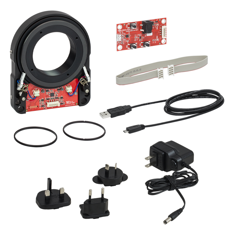
Figure 2.1 Components of the ELL21K Bundle
(One Region-Specific Power Adapter Included with the Power Supply)
Click to Enlarge
Figure 2.2 Mechanical Drawing of the Rotation Mount
For more information on mounting options see the Operation tab.
Click to Enlarge
Figure 2.3 Mechanical Drawing of the Interface Board
| Connector J1 Pinouta | ||
|---|---|---|
| Pin | Type | Function |
| 1 | PWR | Ground |
| 2 | OUT | ODTX - Open Drain, Transmit 3.3 V TTL RS232 |
| 3 | IN | RX Receive - 3.3 V TTL RS232 |
| 4 | OUT | In Motion, Open Drain, Active Low, Max 5 mA |
| 5 | IN | JOG/Mode, Active Low, Max 5 V |
| 6 | IN | BW Backward, Active Low, Max 5 V |
| 7 | IN | FW Forward, Active Low, Max 5 V |
| 8 | PWR | VCC +5 V ±10%; 800 mA |
Click to Enlarge
Figure 3.1 Pinout diagram of the Picoflex® connector is shown referended to a partial diagram
of the ELL21 Rotation Mount Board.
| ELLB Connector J1, J2, J3, and J4 Pinouta,b | ||
|---|---|---|
| Pin | Type | Function |
| 1 | PWR | Ground |
| 2 | OUT | ODTX - Open Drain, Transmit 3.3 V TTL RS232 |
| 3 | IN | RX Receive 3.3 V TTL RS232 |
| 4 | OUT | In Motion, Open Drain, Active Low, Max 5 mA |
| 5 | IN | Not Connected |
| 6 | IN | Not Connected |
| 7 | IN | Not Connected |
| 8 | PWR | VCC +5 V ± 10%; 800 mA per Connected Device |

Click to Enlarge
Figure 3.2 Pinout diagram of the Picoflex® connector is shown referenced to a simplified diagram
of the ELLB Bus Distributor. The polarity indicator on the connector
must be adjacent to the red wire on the supplied 8-connector cables.
Operation Notes
This tab contains information on handling, mounting, and operating the ELL21K(/M) Rotation Mount Bundle.
Contents- Handling
- Mounting and Loading the Rotation Mount
- Supplying Power
- Operation of the Motors
- Positioning the Rotation Mount
- Resonance Frequencies
Click to Enlarge
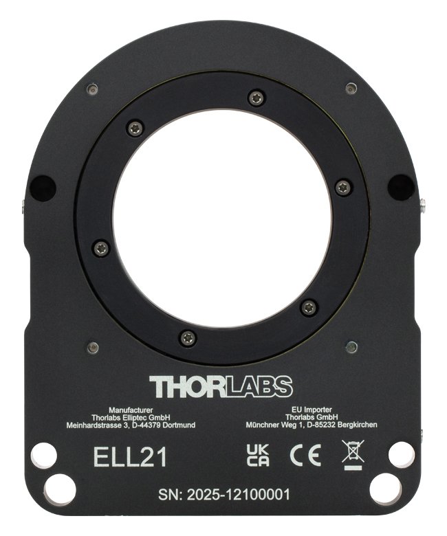
Figure 4.2 The Rotation Mount, Back
Click to Enlarge
Figure 4.1 The Rotation Mount, Front
Handling
The rotation mount and interface board included in the ELL21K(/M) bundle are robust to general handling. To ensure reliable operation, keep the surface of the plastic track contacted by the motors free of oils, dirt, and dust. It is not necessary to wear gloves while handling the rotation mount, but avoid touching the track to keep it free of oils from fingerprints. If it is necessary to clean the track, it may be wiped with isopropyl alcohol or mineral spirits (white spirit). Do not use acetone, as this solvent will damage the plastic track.
ESD precautions should be taken, as an electrostatic discharge can produce an electrical signal that may cause an unintended movement of the mount. Limit the strength of magnetic fields in proximity to the magnetic sensor to ±5 mT to avoid negatively affecting positioning operations.
Mounting and Loading the Rotation Mount
The rotation mount may be mounted either vertically or horizontally. The Elliptec motors should be facing up if the mount is used horizontally. The mount has several mounting features that can be used with Thorlabs components or within a custom OEM assembly. Four 4-40 threaded holes on the back of the mount are spaced 60 mm apart for compatibility with our 60 mm cage system. Each mount also features an 8-32 (M4 x 0.7) tap for post mounting and 1/4" bores for horizontal mounting on a table surface. There are also two Ø6 mm through holes for ER rods and close proximity mounting of two devices. Two additional 6.5 mm deep blind holes for ER05 cage rods ensure alignment of mounts in close proximity.

Click for Details
Figure 4.3 The rotation mount can be mounted in a 60 mm cage system using the 4-40 threaded holes on the back.

Click for Details
Figure 4.4 The rotation mount can be post-mounted and ER cage rods holes allow two mounts to be aligned in close proximity.
Click to Enlarge
Figure 4.5 Features of the Rotation Mount
The maximum allowed weight of the mounted optic is 100 g when mounted vertically and 300 g when mounted horizontally. The load must be centered on the mount in order to achieve these values. In all cases of mounting and loading, ensure that nothing interferes with the moving parts of the rotation mount and that the mount and its load are securely fastened to prevent jostling during movement. Jostling of the stage or the load can cause an encoder error.
Supplying Power
When the setup includes the interface board, power may be supplied through the Micro-B USB connector and/or the 5 VDC power socket located on the board. The electronics on the interface board convert the applied DC signal to a sinusoidal signal oscillating at the required resonance frequency.
The ELL21K(/M) bundle includes a 5 VDC power supply whose connector mates with the power socket on the interface board. Delivering power through this socket also allows the Micro-B USB connector to be used for a computer to control the mount remotely. The power supplied by a computer through the USB 2.0 connection is not sufficient to power the mount. If computer control is not necessary, another option for supplying power to the mount is a CPS1 portable USB 5 V battery pack connected to the Micro-B USB connector on the interface board.
When the implementation does not include the interface board, the connection with the power source is made using the pins on the Picoflex® connector that is included on the rotation mount board. A pinout diagram of this connector is included in the Pin Diagram tab, and information on powering and addressing the rotation mount is given in the manual and the communications protocol manual, respectively.
Click to Enlarge
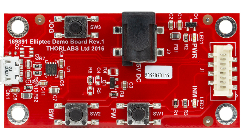
Figure 4.6 The Interface Board

Click to Enlarge
Figure 4.7 Features of the Interface Board
Operation of the Motors
The motion of the rotation mount is controlled by forcing the piezoelectric elements to vibrate at specific ultrasonic frequencies. For each motor, there is one ultrasonic resonant frequency that will push the mount forward, and another that will pull the mount backward. Operating a motor at one of its resonance frequencies causes the tip of the motor to continuously cycle in a tight clockwise elliptical path. When the motor is driven at its other resonant frequency, the tip of the motor cycles through that same path in a counterclockwise direction. Both resonant frequencies are around 100 kHz. The total displacement at the tip of motor is a function of the mechanical load it is driving and the voltage supplied to the piezo element. In the case of no loading and a 5 V maximum driving voltage at a resonant frequency, the tip of the motor expands and contracts no more than a few microns while tracing the elliptical path. Please see The Elliptec® Motor tab for more information and an animation illustrating the operational principle of the motors.
Positioning the Rotation Mount
Note that the rotation mount is not intended for continuous operation. We recommend operation with duty cycles of less than 40% during general use, while operation with duty cycles greater than 60% should be limited to a few seconds.
The movement of the mount may be controlled through computer control via the Elliptec® software package that may be downloaded, or by sending simple signals to digital lines on the mount's board. A link to download the software and accompanying documentation can be found in the Software tab.
Multiple Elliptec devices can be controlled using the ELLB Bus Distributor or by splicing multiple connectors onto one ribbon cable. A single bus distributor can connect up to four Elliptec devices; up to 16 devices can be connected if the buses are daisy chained. This bus can be controlled one of three ways: through an interface board (included with the bundles below) to connect to a PC running the Elliptec software, by connecting to an Arduino® or Raspberry Pi® board, or by wiring the connector pins to a user-supplied control board. Note that if an interface board is used, its on-unit buttons will be disabled. Alternatively, up to 16 devices can be spliced onto a single ribbon cord. The devices can then be simultaneously controlled by the interface board or selectively controlled by the Elliptec software. See the manual for instruction on how to splice multiple devices onto a ribbon cord and the Pin Diagrams tab for pin assignments when making custom connections. The communications protocol manual describes how to use the software to individually address each connected device. A link to download the software and accompanying documentation can be found in the Software tab.
The default increment to move the mount forward and backward is 10°, and a custom increment can be set using the Elliptec software or by sending the appropriate ASCII message(s) as specified in the communications protocol manual. The Elliptec software can be used to move the mount to absolute and relative positions, in addition to jogging the mount forward or backward. The software is also used to set the jog step size, read the position of the mount, and adjust the position of Home, as is described in the previous section.
Readings from the magnetic sensor, which can resolve angular increments of 0.0055° (96 µrad), are used to position the mount and when executing the Home command. The travel range of the mount is not limited, but the reported orientation of the mount is always expressed as a value between 0° and 359.99°. The minimum incremental movement of the mount is 0.0055° (96 µrad), and it can be positioned with a repeatability of 0.05° (0.87 mrad) in response to signals from the magnetic sensor.
Resonance Frequencies
On power-up, the factory default setting instructs each motor driving the rotation mount to search for the resonance frequencies that will deliver the best performance. During this process, the rotation mount will translate a forward and backward by a small amount. If movement on start-up is undesirable, it is possible to disable this calibration procedure by using the serial port to initialize the frequencies on power-up. A new search for optimal resonance frequencies may be performed at any time; to maintain optimal performance, it is recommended that new searches be performed after changes in loading and/or ambient temperature. Please see the manual for details.
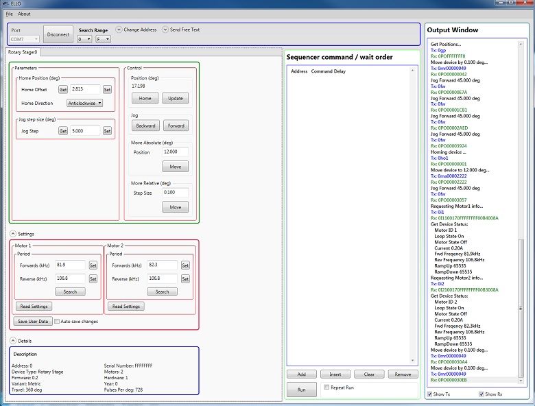
Click to Enlarge
The Elliptec Piezoelectric Resonant Motor Control Software GUI
Software for Devices Driven by Elliptec® Piezoelectric Resonant Motors
All devices based on the Elliptec® resonant piezo motor may be controlled by the Elliptec system software, which features an intuitive graphical user interface (GUI). The source code, in C# format, is included in software bundle available for download, and custom applications can be created in any language. The image at right shows a screen capture of the GUI, and the button that follows links to the download page.
Commands are entered in the Sequencer command / wait order section located at the center-left of the GUI. An example of a sequence of commands that might be sent to the device is "Aho0" to move to the rotation stage at address "A" to the home position in the clockwise direction, and then "Afw" to move the stage at address "A" forward by the jog increment. The command "As1" is used to perform the frequency search that will identify the optimal resonant frequencies, for the current operating conditions, for Motor 1 at adddress "A."
Software
Version 1.6.5 (May 6, 2025)
Includes the Elliptec System Software, with an easy-to-use GUI. Also available for download is the Communications Protocol manual, which details the communication commands for the Elliptec software package.
| Posted Comments: | |
| No Comments Posted |
回転マウント&回転ステージのセレクションガイド
当社では手動式および電動式の回転マウントと回転ステージを豊富にご用意しております。回転マウントの内孔はØ12 mm~Ø12.7 mm(Ø1/2インチ)、Ø25 mm~Ø25.4 mm(Ø1インチ)、またはØ50 mm~Ø50.8 mm(Ø2インチ) の光学素子取付け用に設計されております*。また回転ステージには、様々な部品やシステムが取り付けられるようにタップ穴が配置されております。電動式は、DCサーボモータ、2相ステッピングモータ、あるいはElliptec™共振ピエゾモータにより駆動されます。いずれも360°の連続回転が可能です。
*下表のマウントは、Ø12.7 mm、Ø25.4 mm、Ø50.8 mmの光学素子に対して最適設計されています。Ø12.0 mm、Ø25.0 mm、Ø50.0 mmなどの少し小さい光学素子に対してもご使用いただけますが、光学素子の偏心が重要ではない用途でのご使用をお勧めします。
手動回転マウント
| Rotation Mounts for Ø1/2" Optics | |||||||
|---|---|---|---|---|---|---|---|
| Item # | MRM05(/M) | RSP05(/M) | CRM05 | PRM05(/M)a | SRM05 | KS05RS | CT104 |
| Click Photo to Enlarge | 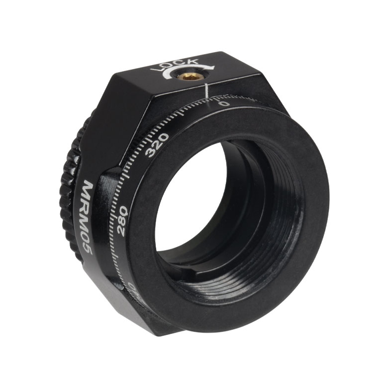 |  | 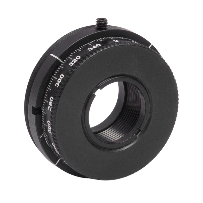 | 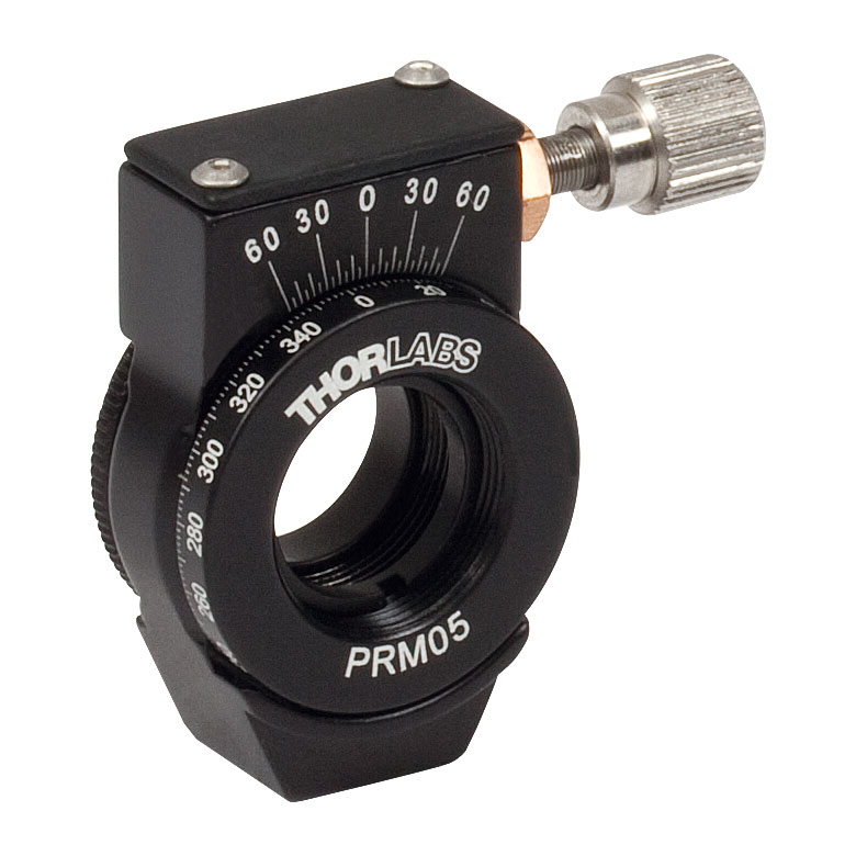 | 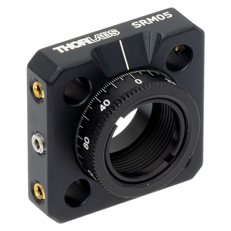 | 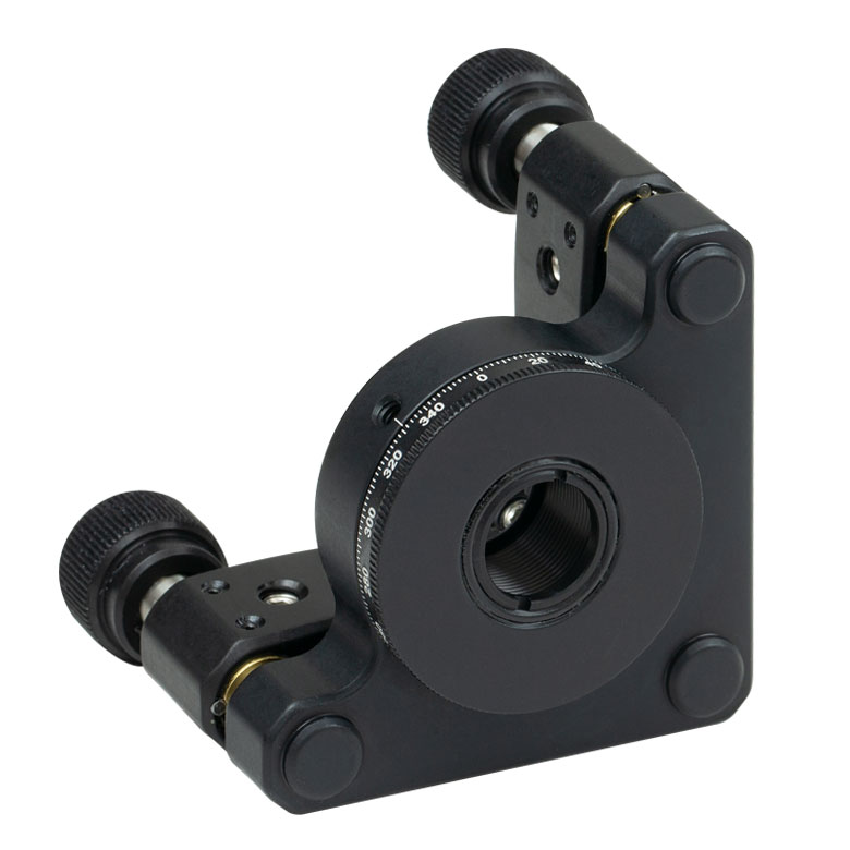 |  |
| Features | Mini Series | Standard | External SM1 (1.035"-40) Threads | Micrometer | 16 mm Cage-Compatible | ±4° Kinematic Tip/Tilt Adjustment Plus Rotation | Compatible with 30 mm Cage Translation Stages and 1/4" Translation Stagesb |
| Additional Details | |||||||
| Rotation Mounts for Ø1" Optics | ||||||||
|---|---|---|---|---|---|---|---|---|
| Item # | RSP1(/M) | LRM1 | RSP1D(/M) | DLM1(/M) | CLR1(/M) | RSP1X15(/M) | RSP1X225(/M) | PRM1(/M)a |
| Click Photo to Enlarge | 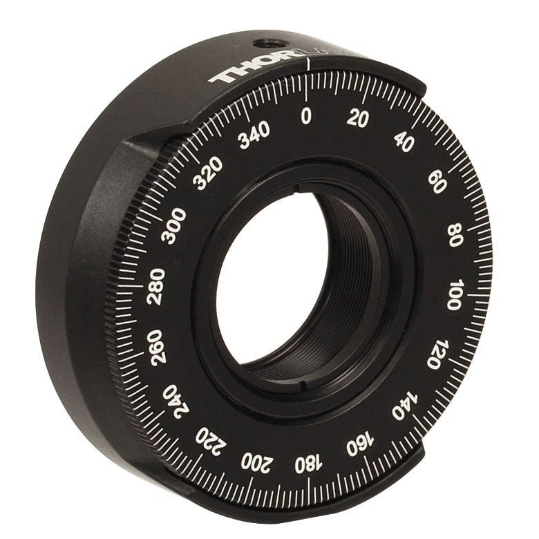 | 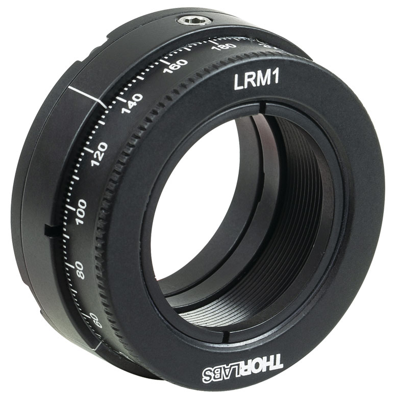 |  | 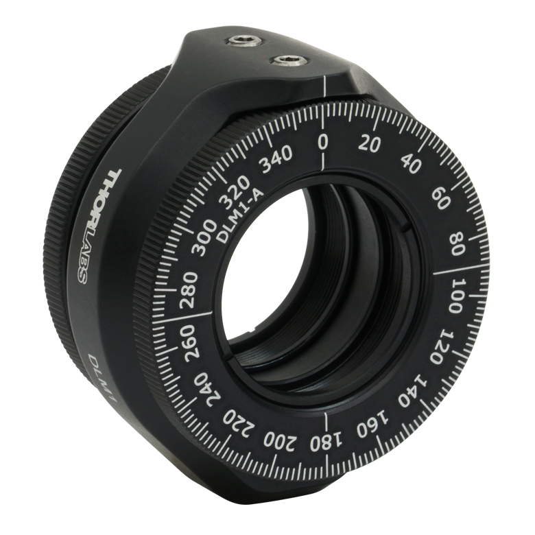 | 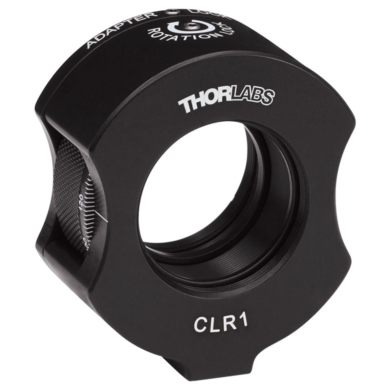 | 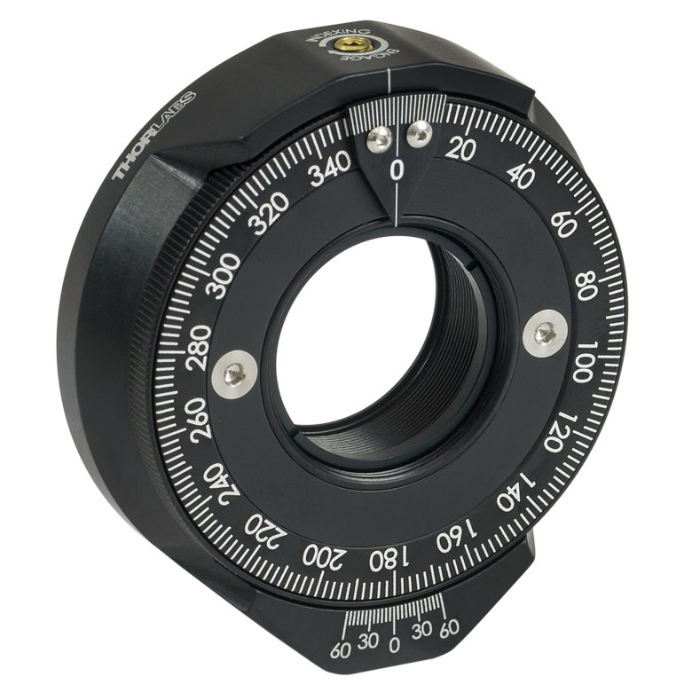 | | 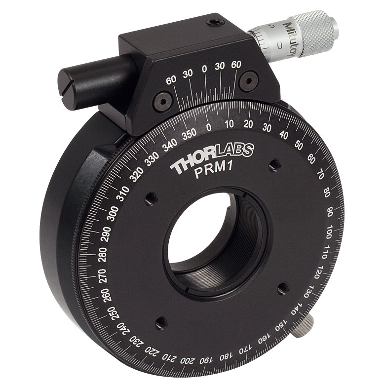 |
| Features | Standard | External SM1 (1.035"-40) Threads | Adjustable Zero | Two Independently Rotating Carriages | Rotates Optic Within Fixed Lens Tube System | Continuous 360° Rotation or 15° Increments | Continuous 360° Rotation or 22.5° Increments | Micrometer |
| Additional Details | ||||||||
| Rotation Mounts for Ø1" Optics | ||||||
|---|---|---|---|---|---|---|
| Item # | LM1-A & LM1-B(/M) | CRM1T(/M) | CRM1LT(/M) | CRM1PT(/M) | KS1RS | K6XS |
| Click Photo to Enlarge | 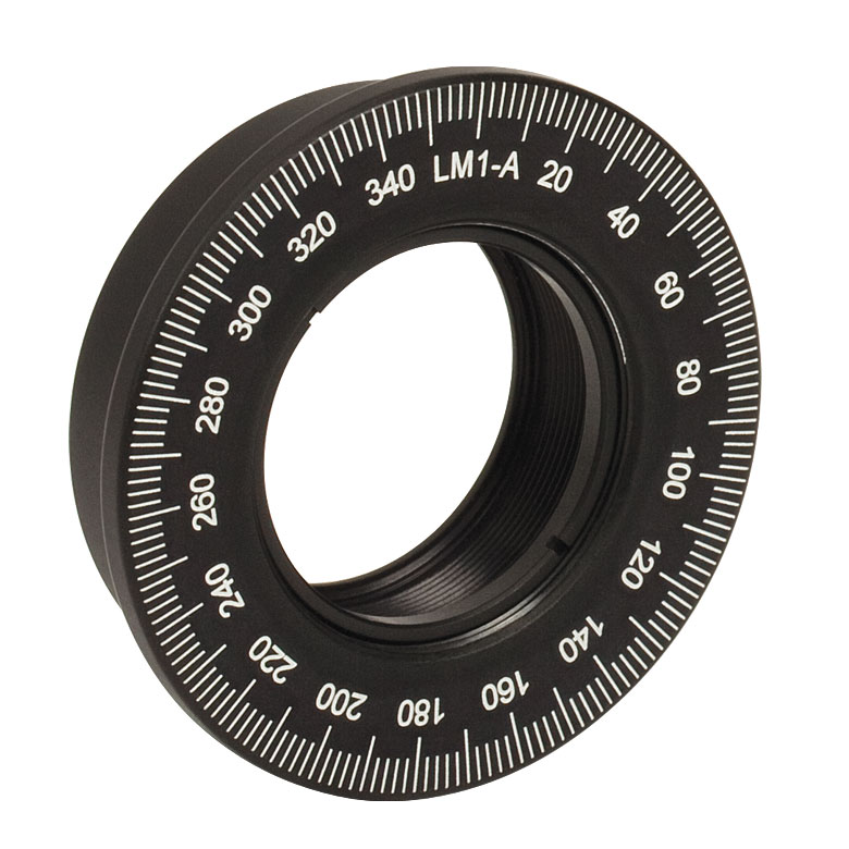 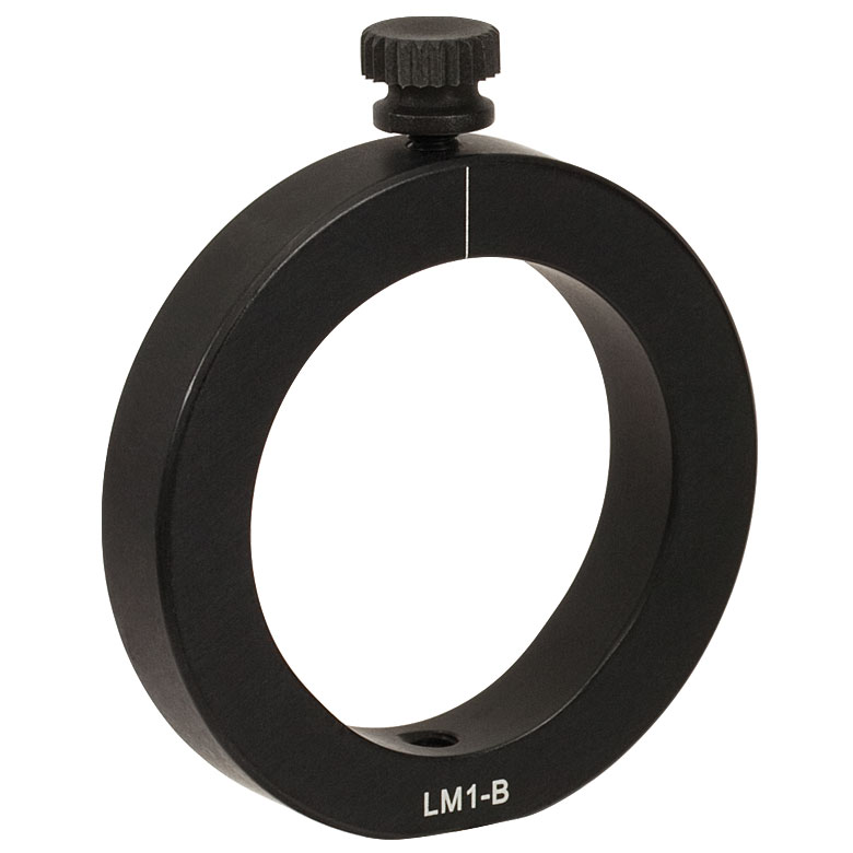 | 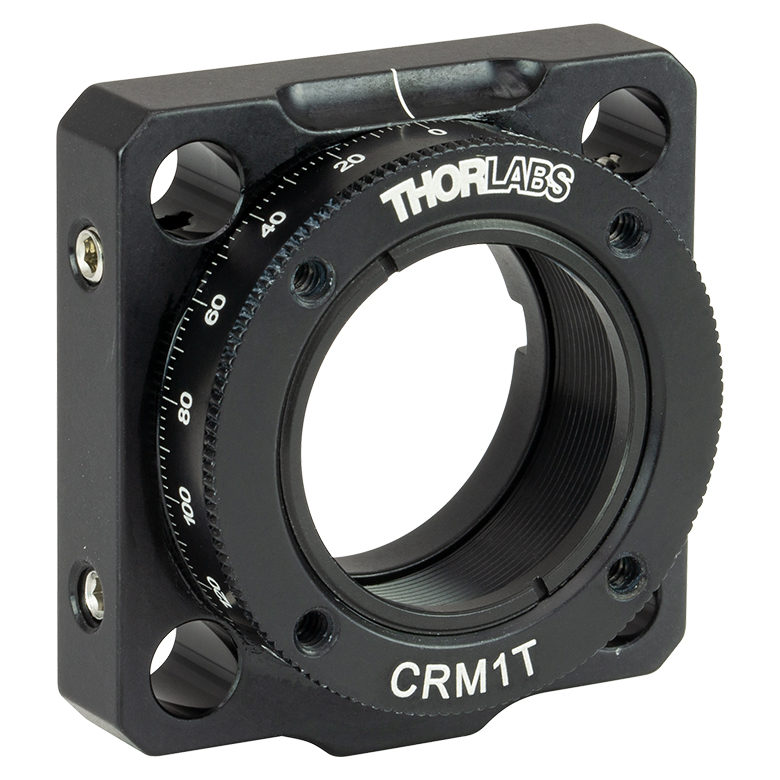 |  |  | 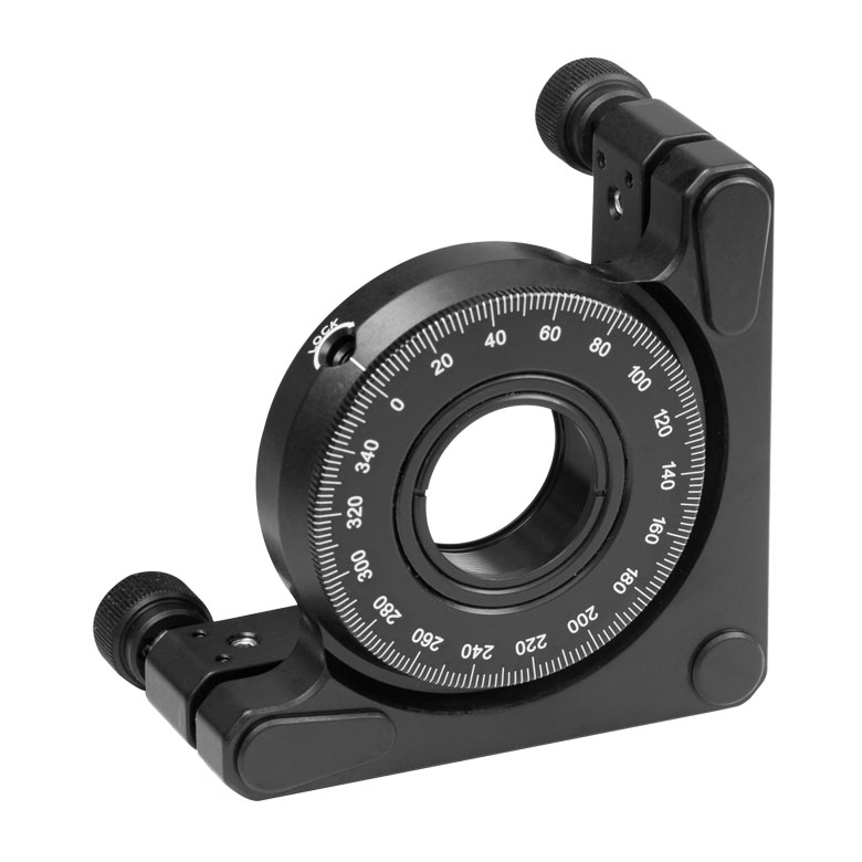 | 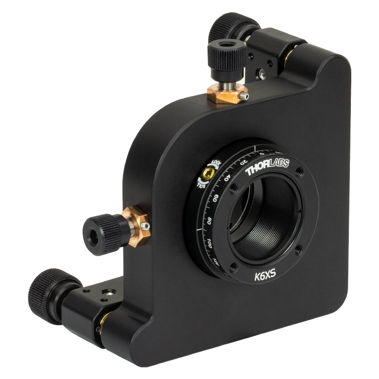 |
| Features | Optic Carriage Rotates Within Mounting Ring | 30 mm Cage-Compatiblea | 30 mm Cage-Compatible for Thick Opticsa | 30 mm Cage-Compatible with Micrometera | ±4° Kinematic Tip/Tilt Adjustment Plus Rotation | Six-Axis Kinematic Mounta |
| Additional Details | ||||||
| Rotation Mounts for Ø2" Optics | |||||||
|---|---|---|---|---|---|---|---|
| Item # | RSP2(/M) | RSP2D(/M) | PRM2(/M) | LM2-A & LM2-B(/M) | LCRM2A(/M) | KS2RS | K6X2 |
| Click Photo to Enlarge |  | 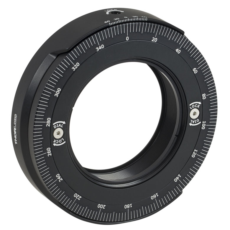 | 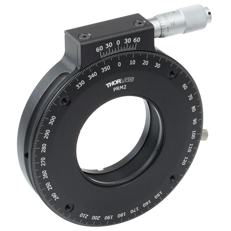 | 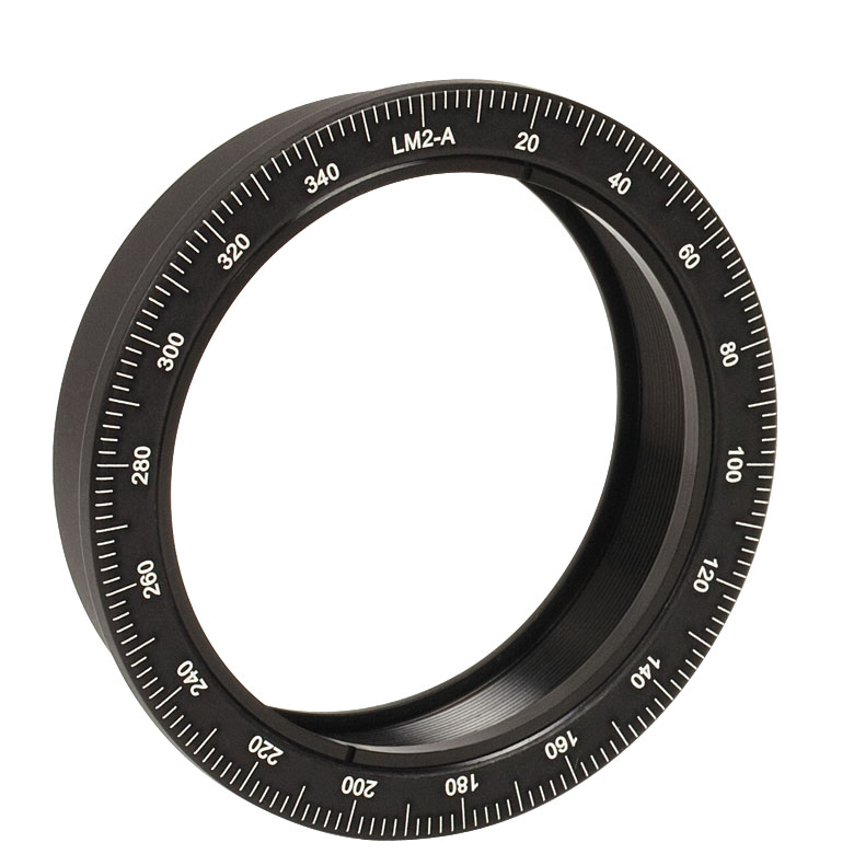 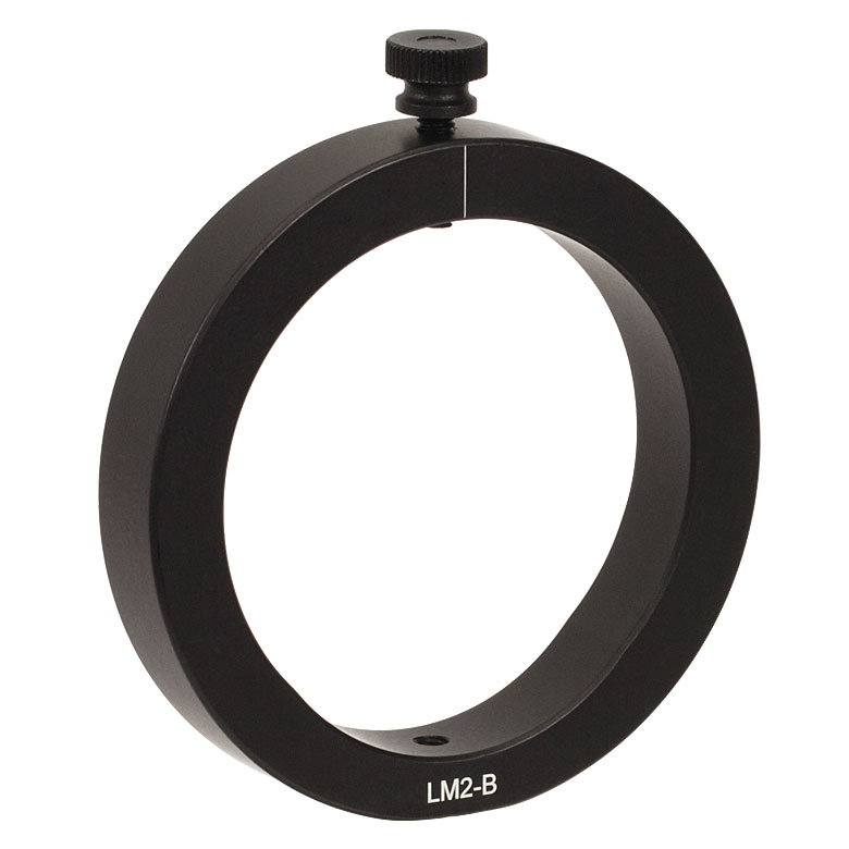 |  |  | 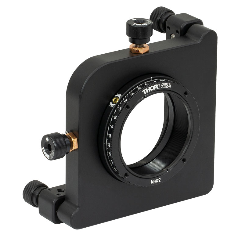 |
| Features | Standard | Adjustable Zero | Micrometer | Optic Carriage Rotates Within Mounting Ring | 60 mm Cage-Compatible | ±4° Kinematic Tip/Tilt Adjustment Plus Rotation | Six-Axis Kinematic Mount |
| Additional Details | |||||||
| Rotation Drive Mechanism and Adjustment Range | Manual, 360° Continuous | Coarse: Manual, 360° Continuous; Fine: ±7° Micrometer | Manual, 360° Continuous | ||||
| Optic Mounting | Internally SM2-Threaded Carriage | Internal SM2 Threads in LM2-A | Internally SM2-Threaded Carriage | ||||
| Maximum Accepted Optic Thickness | 0.51" (13 mm) | 0.54" (13.7 mm) | 0.48" (12.2 mm) | 0.46" (11.7 mm) | 0.52" (13.2 mm) | 0.47" (12 mm) | 0.53" (13.4 mm) |
| Post Mounting | 8-32 (M4) Tap | 8-32 (M4) Tap in LM2-B | 8-32 (M4) Tap | Four Counterbores for 8-32 (M4) Cap Screws | Six Counterbores for 8-32 (M4) Cap Screws | ||
| Cage System Compatibility | N/A | Four 4-40 (M3) Taps on Rotation Dial with 60 mm Spacing | N/A | Four Bores for Ø6 mm Cage Rods with 60 mm Spacing | N/A | N/A | |
手動回転ステージ
| Manual Rotation Stages | ||||||
|---|---|---|---|---|---|---|
| Item # | RP005(/M) | PR005(/M) | MSRP01(/M) | RP01(/M) | RP03(/M) | QRP02(/M) |
| Click Photo to Enlarge | 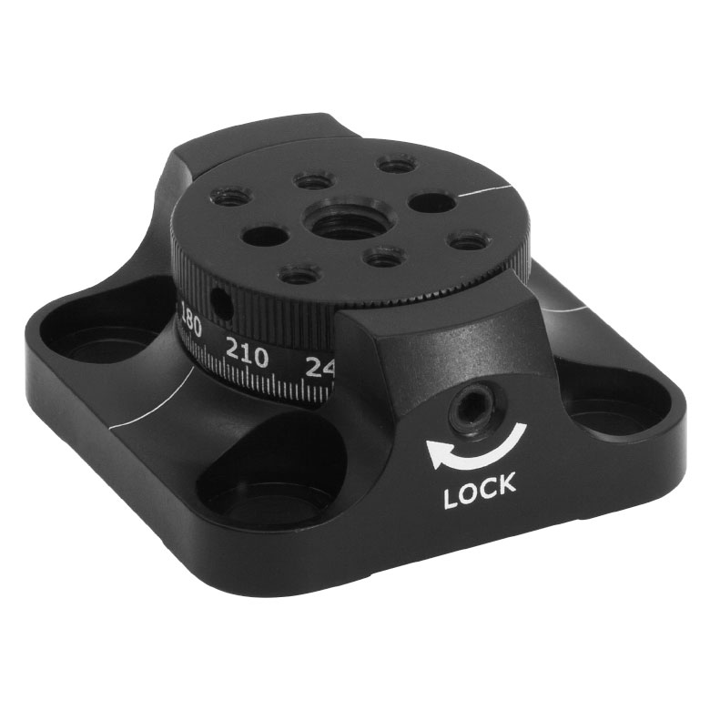 | 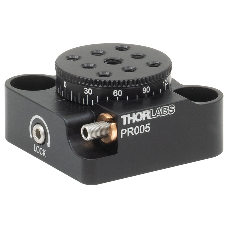 | 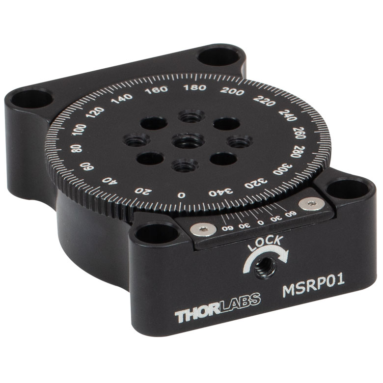 | 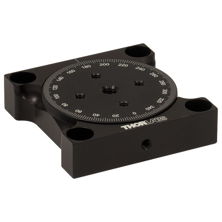 | 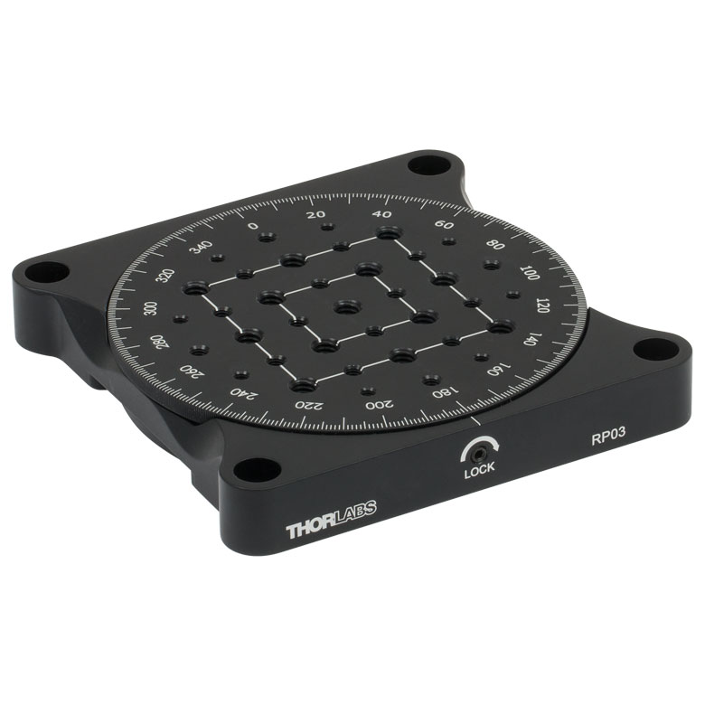 | 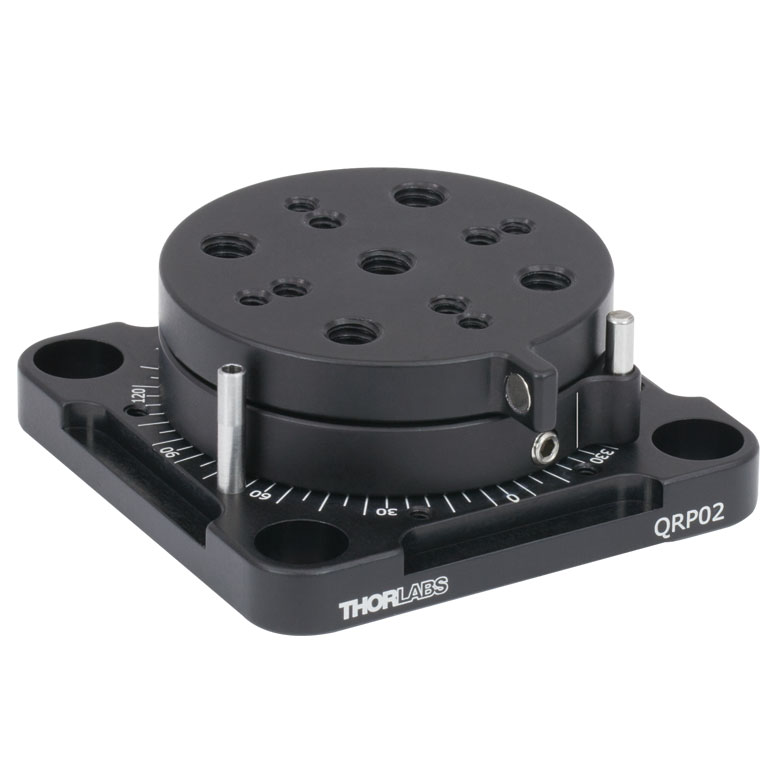 |
| Features | Standard | Two Hard Stops | ||||
| Additional Details | ||||||
| Manual Rotation Stages | ||||||
|---|---|---|---|---|---|---|
| Item # | XRNR1(/M) | XRR1(/M) | PR01(/M) | CR1(/M) | XYR1(/M) | OCT-XYR1(/M) |
| Click Photo to Enlarge | 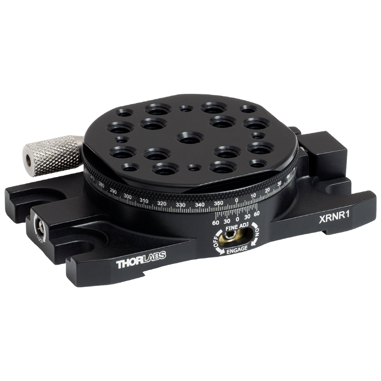 |  | 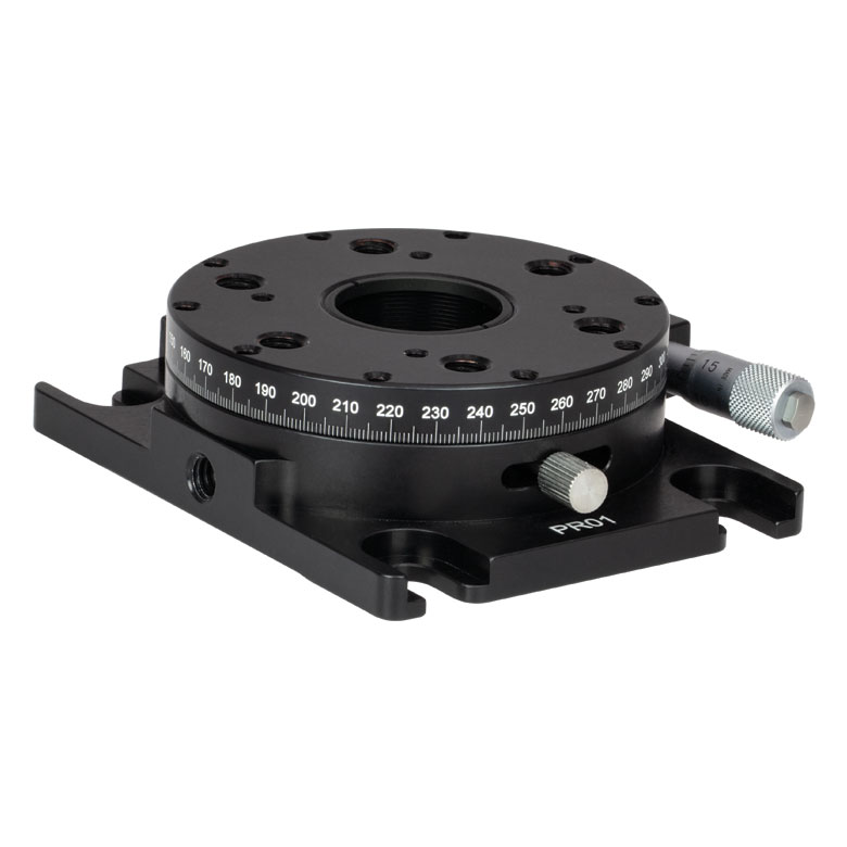 | 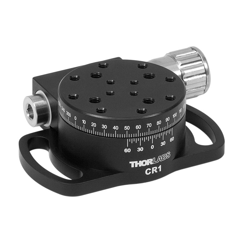 | 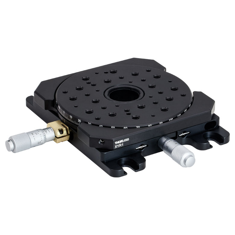 | 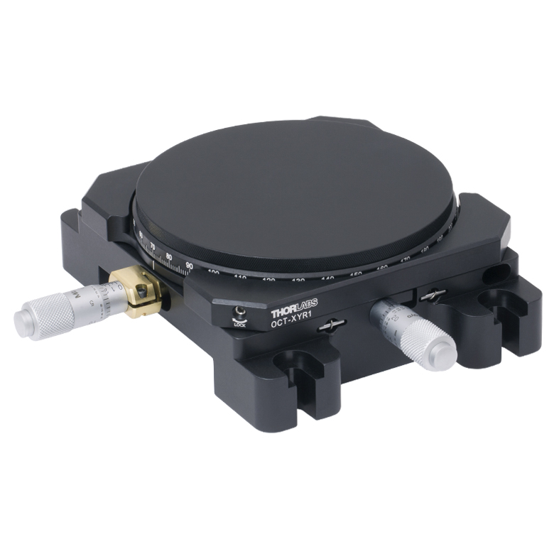 |
| Features | Fine Rotation Adjuster and 2" Wide Dovetail Quick Connect | Fine Rotation Adjuster and 3" Wide Dovetail Quick Connect | Fine Rotation Adjuster and SM1-Threaded Central Aperture | Fine Pitch Worm Gear | Rotation and 1/2" Linear XY Translation | |
| Additional Details | ||||||
電動回転マウント&ステージ
| Motorized Rotation Mounts and Stages with Central Clear Apertures | |||||
|---|---|---|---|---|---|
| Item # | DDR25(/M) | PDR1C(/M) | PDR1(/M) | PDR1V(/M) | PDXR1(/M) |
| Click Photo to Enlarge | 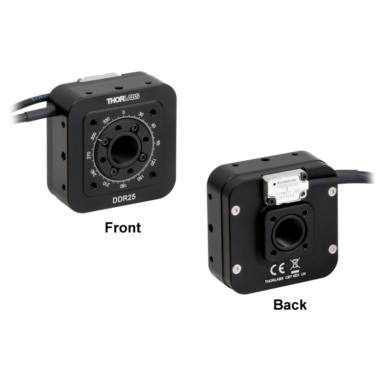 | 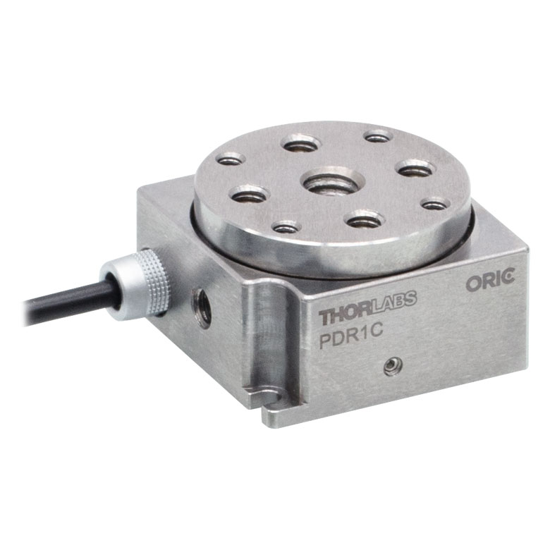 | 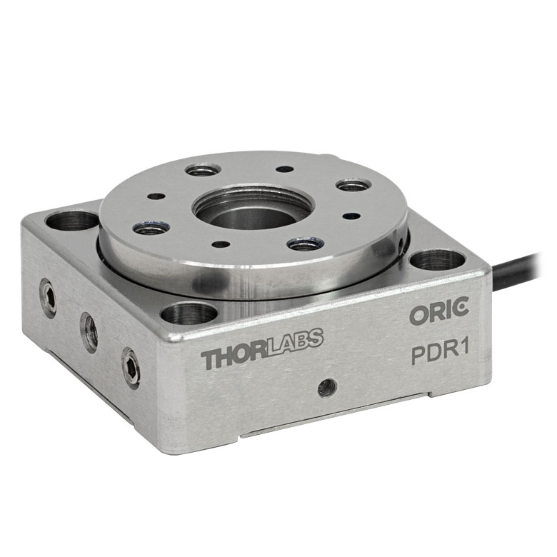 |  |  |
| Features | Compatible with SM05 Lens Tubes, 16 mm Cage System, & 30 mm Cage System | Compatible with 16 mm Cage System | Compatible with SM05 Lens Tubes & 30 mm Cage System | Vacuum-Compatible; Also Compatible with SM05 Lens Tubes & 30 mm Cage System | Compatible with SM05 Lens Tubes & 30 mm Cage System |
| Additional Details | |||||
| Motorized Rotation Mounts and Stages with Central Clear Apertures | |||||||
|---|---|---|---|---|---|---|---|
| Item # | K10CR1(/M) | PRM1Z8(/M)a | DDR100(/M) | ELL16 | ELL14 | ELL21(/M) | HDR50(/M) |
| Click Photo to Enlarge | 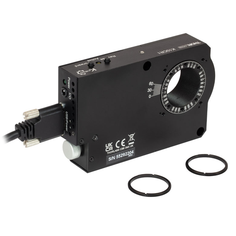 | 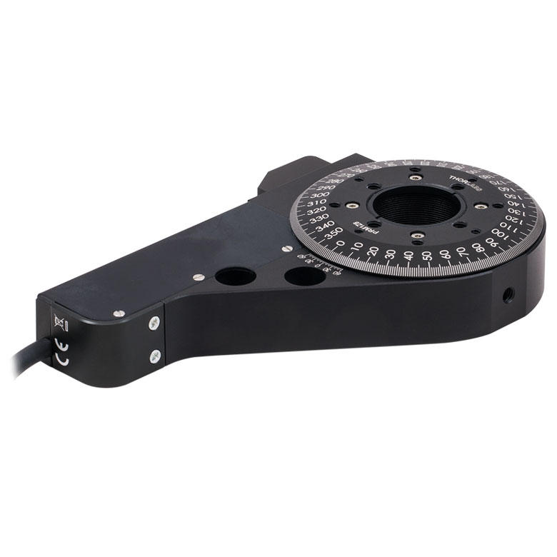 | 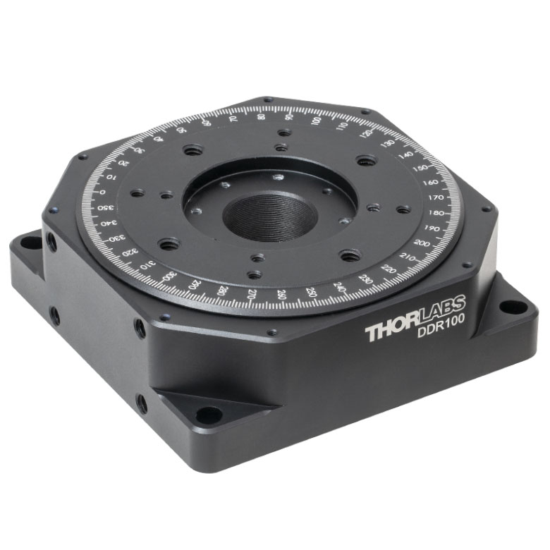 |  | 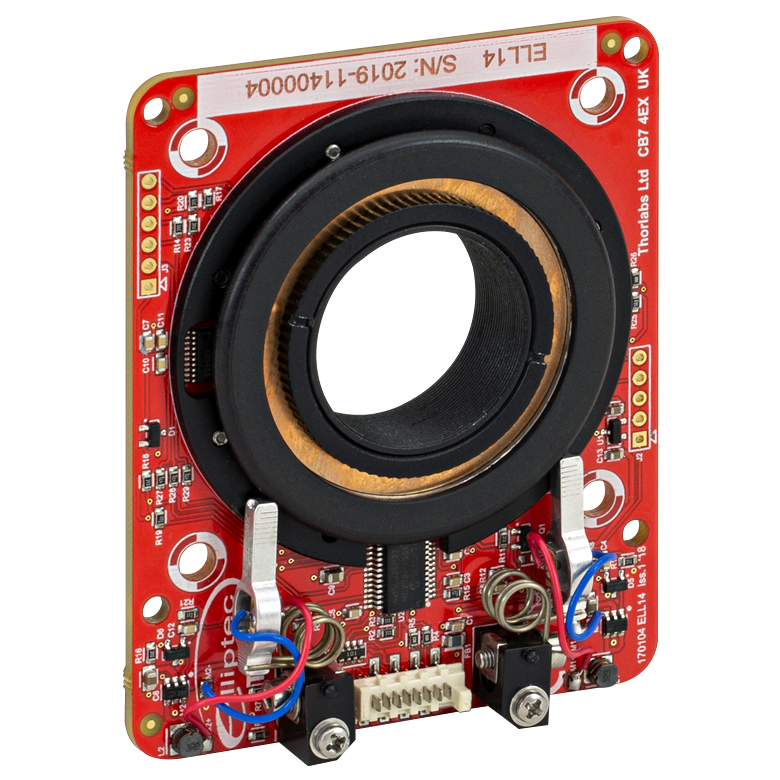 | 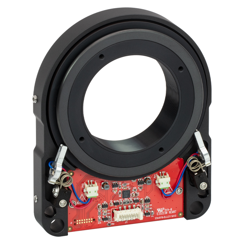 | 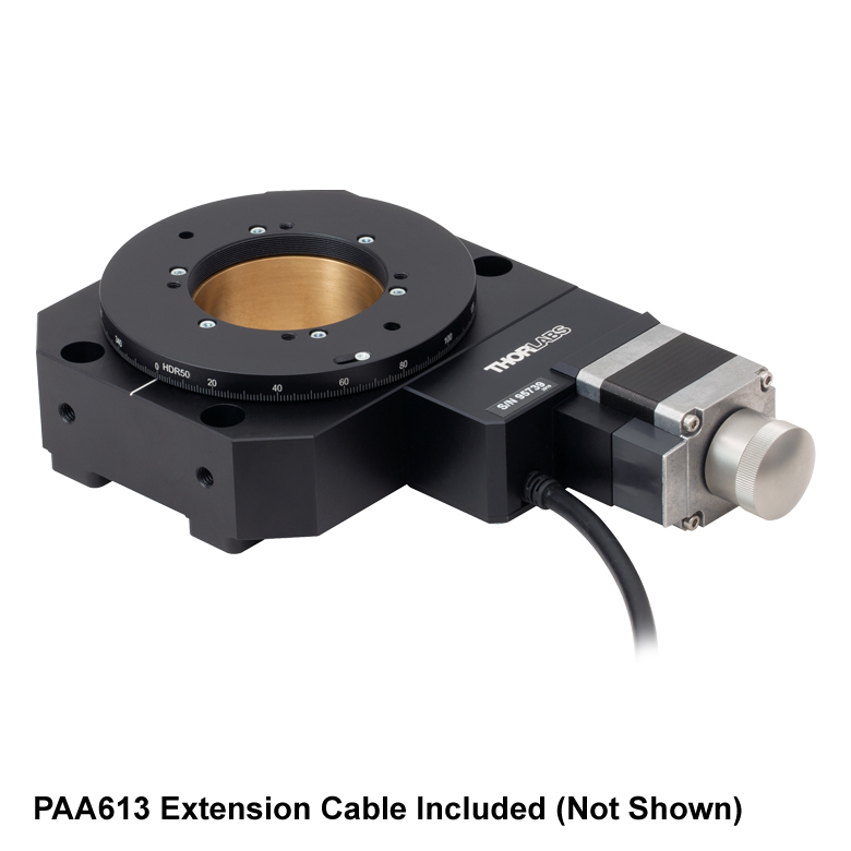 |
| Features | Compatible with SM1 Lens Tubes & 30 mm Cage System | Compatible with SM1 Lens Tubes, 16 mm Cage System, 30 mm Cage System | Compatible with SM05 Lens Tubes, Open Frame Design for OEM Applications | Compatible with SM1 Lens Tubes, Open Frame Design for OEM Applications | Compatible with SM2 Lens Tubes, Open Frame Design for OEM Applications | Compatible with SM2 Lens Tubes | |
| Additional Details | |||||||
| Motorized Rotation Mounts and Stages with Tapped Platforms | ||
|---|---|---|
| Item # | PRMTZ8(/M)a | ELL18(/M)b |
| Click Photo to Enlarge | 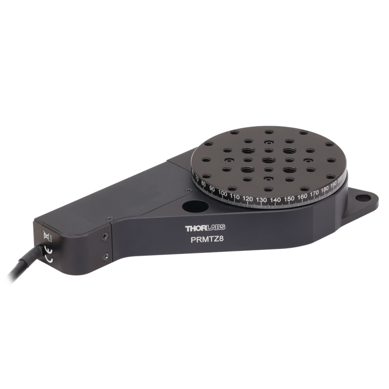 | 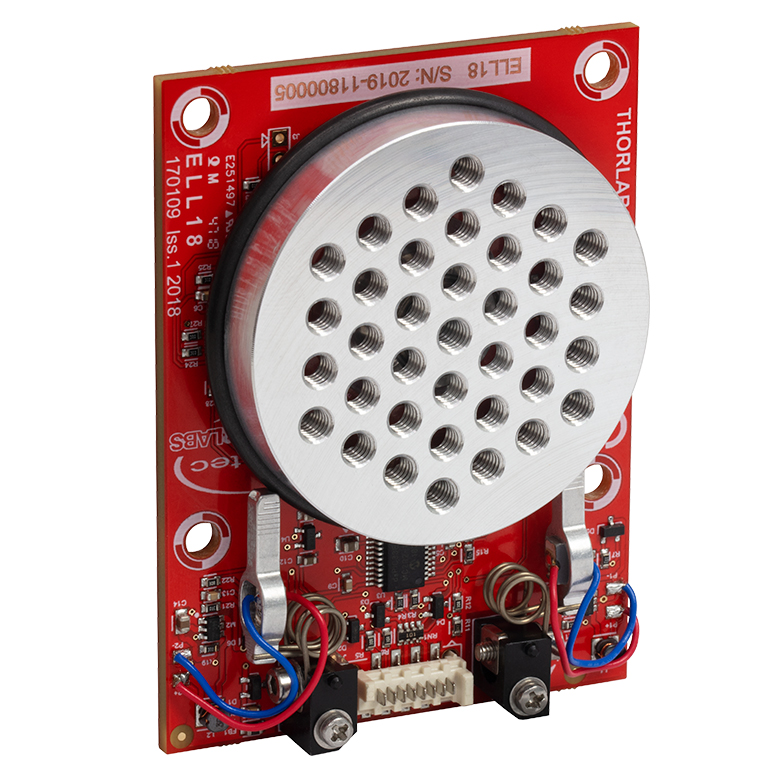 |
| Features | Tapped Mounting Platform for Mounting Prisms or Other Optics | Tapped Mounting Platform, Open Frame Design for OEM Applications |
| Additional Details | ||

 ズーム
ズーム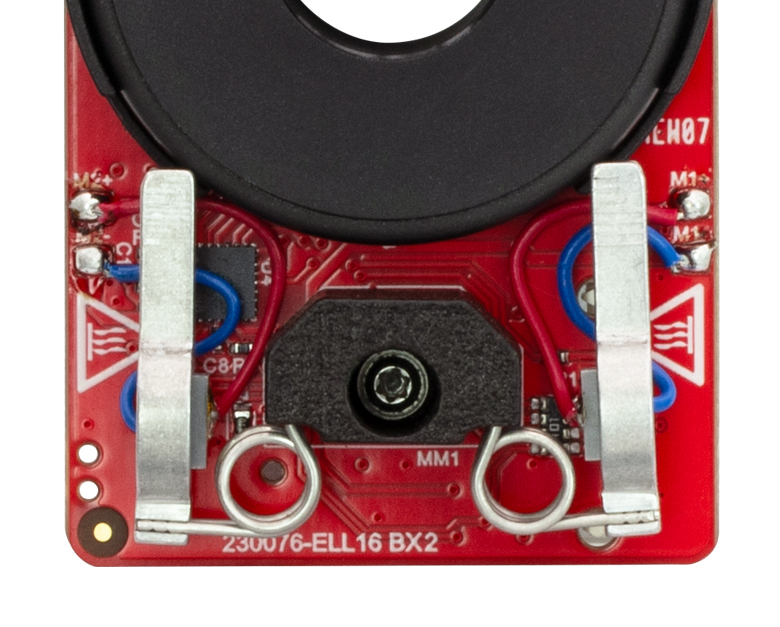
Click to Enlarge
Figure G1.1 The motors' aluminum tips contact the black plastic track encircling the rotation mount. This track should not be touched to prevent debris and oil building up on the track.
- Ideal for OEM Evaluation Testing
- Easily Integrate into a Setup
- Operate using Manual and/or Computer Control
- Included Power Supply is Required for Powering the Mount
The Rotation Mount Bundle is a complete package that includes the ELL21(/M) rotation mount. The ELL21K(/M) package facilitates quick integration of the rotation mount into laboratory setups and other experimental applications. It also provides a convenient means to evaluate incorporating this technology into OEM applications.
The tips of both motor housings are in firm contact with the plastic track encircling the rotation mount, as can be seen in Figure G1.1. The motors are installed with opposite orientations and clockwise (and counterclockwise) rotation occurs when one motor pushes the track forward while the other pulls it backward.
| Included in the ELL21K(/M) Bundle | |
|---|---|
| ELL21(/M) Rotation Mount | 5 V Power Supply with Region-Specific Power Adapter |
| Interface Board | 8-Conductor 28 AWG Ribbon Cable |
| Micro-B USB Cable | PC-Based Software for Download |

 ズーム
ズームClick to Enlarge
Figure G2.1 Features of the ELL21(/M) Rotation mount
The ELL21(/M) Rotation Mount is offered to meet the needs of applications whose designs require multiple networked Elliptec® resonant motor products. It possesses an SM2-threaded bore for mounting Ø2" optics. Details describing the dimensions, including the spacing of mounting holes, and other specifications of the mount are given in the Specs tab. Please contact us to discuss customizing the rotation mount.
The PCB of the rotation mount incorporates a male 8-pin Picoflex® connector (header). Each ELL21(/M) mount ships with the female 8-pin Picoflex® connector (receptacle) that mates with the connector (header) on the board.

 ズーム
ズーム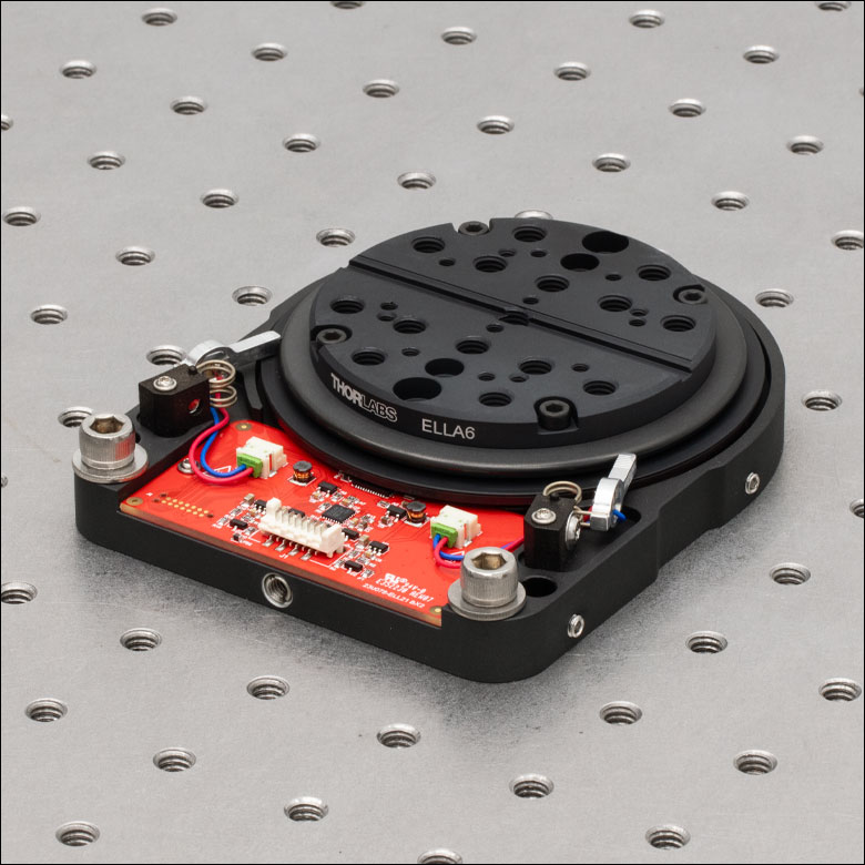
- Adapters Attach Using M3 Counterbores
- ELLA6(/M) Adapter Features:
- 3 mm Keyway for Fiber Alignment Accessories
- 4-40 Mounting Holes for 30 mm Cage System
- 1/4"-20 (M6 x 1.0), 6-32 (M3 x 0.5), 4-40 (M3 x 0.5) Taps
- ELLA7(/M) Adapter Features:
- SM1 (1.035"-40) Thread for Ø1" Lens Tubes and Mounted Optics
- 4-40 Mounting Holes for 30 mm Cage System
- 1/4"-20 (M6 x 1.0) and 6-32 (M3 x 0.5) Taps
- ELLA8 Adapter Features Five SM05 (0.535"-40) Threaded Bores for Ø1/2" Lens Tubes or Mounted Optics
These adapter plates provide additional mounting features for the ELL21(/M) Rotation Mount. The plates mount to the moving world using four included (M3 x 0.5) screws. Note that imperial and metric adapters are compatible with either type of stage. All three adapters are also compatible with our HDR50(/M) rotation stage and the ELLA6(/M) and ELLA7(/M) adapters are also compatible with the PRM1(/M)Z8 rotation stage.
The ELL6(/M) adapter features an array of mounting holes for compatibility with stages and mounts including the GN05(/M) small goniometric stage, MS series 1/4" travel stages, T12 series 1/2" travel stages, and BSH series cube and prism mounts.
Click for Details
Figure G3.4 ELLA8 5-Position SM05-Threaded Adapter Plate


 ズーム
ズーム| Specifications | ||
|---|---|---|
| Item # | ELLC2 | |
| DC Voltage Input to Controller | 4.5 to 5.5 V | |
| Typical Current Consumption Per Module | Movement | 800 mA |
| Standby | 50 mA | |
| Operating Temperature Range | 15 to 40 °C | |
| Ribbon Cable Length (1 Included) | 250 mm (9.8") | |
| Dimensions (Interface Board Only) | 66.0 mm x 32.0 mm x 12.5 mm (2.60" x 1.26" x 0.49") | |
| Weight (Interface Board Only) | 10.8 g (0.022 lbs) | |
- 単品のELLシリーズ製品に追加して1組のキットを構成するための下記のコンポーネントのセット
- インターフェイスボード
- USB Micro Bケーブル
- Picoflex®1ケーブル
- 5 V電源、国内対応アダプタ
アップグレード用アクセサリーキットELLC2は、単品のELLシリーズのスライダ、ステージ、マウントをお持ちの場合に、それに追加して上記のようなELLセット一式2とするためのコンポーネントを揃えたキットです。接続されたELLステージの位置は、付属のハンドヘルドコントローラの3つのボタンで制御することができます。またUSBポートと付属のUSB Micro Bケーブルを介して、PCと直接接続することができます。キットには、ハンドヘルドコントローラとELLデバイスを接続するための0.25 mのPicoflex®ケーブル(8負荷回路)と、5 V電源(国内対応アダプタ付き)も含まれています。
- 注: Picoflex®はMolex社の登録商標です。
- ELL17/M、ELL18/MおよびELL20/M用の取付けブラケットのご注文は当社までご連絡ください。
| Included in the ELLC2 Accessory Upgrade Kit | |
|---|---|
| USB 2.0 Micro-B Cable, 1.5 m Long | 5 V Power Supply with Region-Specific Power Adapter, 1.5 m Long |
| Interface Board | 8-Conductor 28 AWG Ribbon Cable, 250 mm Long |

 ズーム
ズーム| Specifications | ||
|---|---|---|
| Item # | ELLB | |
| Voltage Rating | 4.5 to 5.5 V | |
| Typical Current Consumption Per Module | Movement | 800 mA |
| Standby | 50 mA | |
| Maximum Board Current | 4.0 A | |
| Operating Temperature Range | 15 to 40 °C | |
| Ribbon Cable Length (4 Included) | 250 mm | |
| Maximum Supported Ribbon Cable Length | 500 mm | |
| Dimensions | 65.0 mm x 32.0 mm x 12.5 mm (2.56" x 1.26" x 0.49") | |
| Weight | 11 g (0.02 lbs) | |
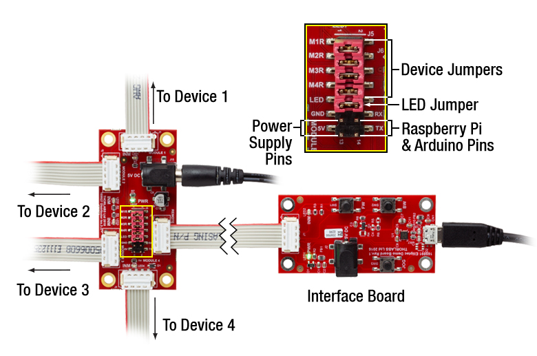
Click to Enlarge
Figure 683A 1個のバス分配器で最大4個のElliptecデバイスを制御できます。バスは上記のセットに付属しているインターフェイスボードでPCに接続可能です。このときバスはElliptecソフトウェアによって制御され、インターフェイスボード上のボタンは無効になっていますのでご注意ください。
- 1つのバスで最大4台までのElliptec®デバイスに対する制御と電源供給が可能
- 分配器をデイジーチェーン接続すると最大16台までのElliptecデバイスを制御可能
- Elliptecシステムソフトウェア(上記の「ソフトウェア」タブ参照)によるリモート制御
- Elliptec製品のセットに付属するUSBインターフェイスボードを使用してPCに接続可能
- ジャンパ5個およびリボンケーブル(8芯、AWG28)4本が付属
- Raspberry Pi®とArduino®ボードにも対応
バス分配器ELLBには、最大4台までのElliptec®デバイスを接続できます。 接続されたデバイスは上記のセットに付属するインターフェイスボードで制御可能ですが、それが無くても制御できます。インターフェイスボードを使用する場合は、接続された各デバイスはElliptecソフトウェアパッケージが動作するPCによってリモート制御されます。インターフェイスボードは、分配器のREMOTEと記載されているバス信号の入力ポートに接続します。この接続を行うと、インターフェイスボードのボタンは無効になります。インターフェイスボードを使用せずにカスタム接続する場合は、「ピン配列」タブをご覧ください。
複数のバス分配器ELLBをデイジーチェーン接続すると、最大16台までのElliptecデバイスに対する制御と電源供給が可能になります。単純に4つの出力ポート(MODULE)の内の1つを、次のボードの入力ポート(REMOTE)に接続するだけで動作します。LEDインジケータによりどのデバイスが動作しているかが示されます。ソフトウェアで各デバイスを個別にアドレス指定する方法については、通信プロトコルマニュアルをご参照ください。ソフトウェアと付属文書のダウンロードリンクは「ソフトウェア」タブにございます。
バス分配器には、最大電流4 Aの5 V電源を接続するためのØ6.3 mm電源コネクタが付いています。より多くのデバイスを接続して各ユニットを同時に制御するには、電源からより多くの電流を供給する必要があります。 各Elliptecデバイスによって消費される電流については、「仕様」タブをご覧ください。5V、2 Aの電源がELL9およびELL12に付属しています。接続されたElliptecデバイスの消費電流に応じて、電源は同時に2つのデバイスに対して電流の供給ができます。
機能を追加するための制御ピンが14個付いています(Figure 683A参照)。ピンの4組のペアがそれぞれジャンパで短絡されているとき、つまりジャンパがセットされているときは、Elliptecソフトウェアは接続されたElliptecデバイスからのフィードバック信号を受信することができます。 LEDと記載されているピンのペアはジャンパで短絡されていますが、これを取り外すとLEDインジケータは無効になります。 5VとGNDと記載されたピンを用いると、Ø6.3 mm電源コネクタに接続された電源の代わりに、お手持ちの5 V、2 A 電源を使用することができます。 RX とTX と記載されたピンを用いると、Elliptecインターフェイスボードの代わりに、Raspberry Pi®やArduino®ボードでバスを制御することができます。
ボードは四隅にあるØ3.5 mm貫通穴を使用して取り付けます。リボンケーブル(8芯、AWG28)は4本付属します。
| Compatible Elliptec Devices | |||||
|---|---|---|---|---|---|
 |  |  |  |  |  |
| Multi-Position Sliders | 28 mm Linear Stage | 60 mm Linear Stage | Rotation Stage | Rotation Mount | Motorized Iris |