 Products Home
共振ピエゾモーター付きマルチポジションスライダー

- Mount Multiple SM05- or SM1-Threaded Components
- Open Frame Design for OEM Applications
- Control via Interface Board, GUI, or ASCII Message Calls
- Fully Integrated Drive Electronics
Application Idea
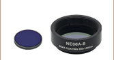
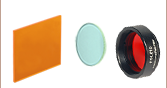
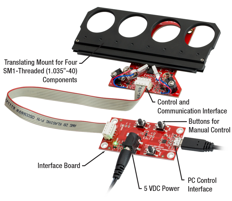
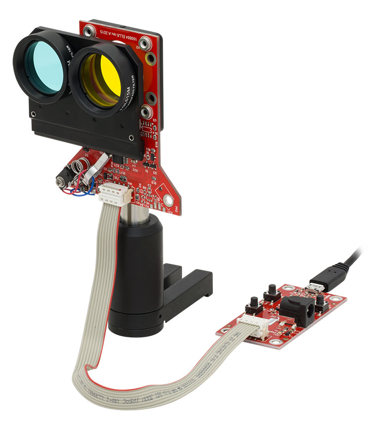
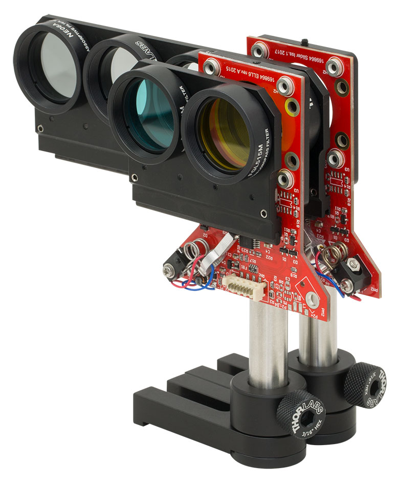
ELL6K Bundle Components Shown Assembled, with Two Colored Glass Filters, and Mounted Using the ELLA1 Adapter
Four-Position Slider
(Also Available Individually)
Interface Board
ELL9K
Four-Position
Slider Bundle
(Board and Slider Included)
ELLB
Bus Distributor


Please Wait
| Key Specsa | |||
|---|---|---|---|
| Item # | ELL12(K) | ELL6(K) | ELL9(K) |
| Ports for Mounted Optics | Six, SM05 Threaded | Two, SM1 Threaded | Four, SM1 Threaded |
| Switching Time Range | No Load: 350 to 400 ms 150 g Load: < 600 ms | No Load: 180 to 270 ms 100 g Load: < 600 ms | No Load: 450 to 500 ms 150 g Load: < 700 ms |
| Positioning Repeatability | < 100 µm (30 µm Typical) | ||
| Maximum Total Loadb | 150 g (5.29 oz) | ||
| DC Voltage Input | 4.5 to 5.5 V | ||
| Weight (Slider Only) | 78.5 g (2.77 oz) | 44.0 g (1.55 oz) | 70.0 g (2.47 oz) |
| Minimum Lifetimec | 3.3 Million Operations or 100 km Total Travel | ||
| Elliptec Resonant Motor Products | |||||
|---|---|---|---|---|---|
 |  |  |  |  |  |
| Multi-Position Sliders | 28 mm Linear Stage | 60 mm Linear Stage | Rotation Stage | Rotation Mount | Motorized Iris |
 製品組み込み用(OEM用)のElliptec技術
特長
- 製品組み込み(OEM)や高速での切り替えが必要な用途向け
- 制御信号用としてMicro-B USBおよびPicoflex®1
- マルチドロップ接続用のシリアル通信プロトコルをサポート
- SM05またはSM1の内ネジ付きポート、マウント付き光学素子やその他の部品の取り付け用
- フォトインターラプタ光学センサを用いた精密な位置決め
- 30 mmケージシステム用部品に対応
- バス分配器、ポスト取付け用アダプタ、アップグレード用アクセサリーキットをご用意(下記参照)
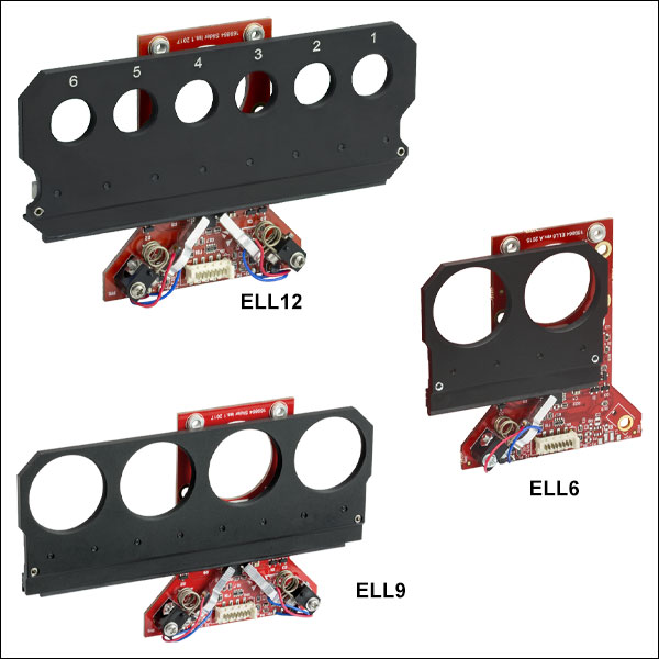
当社では、Elliptec®共振ピエゾモータ技術を用いた、切り替え時間が数100ミリ秒程度のマルチポジションスライダをご用意しております。スライダは単体、またはインターフェイスボードを含むセットでご用意しております。単品のスライダをコンプリートセットにアップグレードするためのアクセサリーキットもご用意しております。当社のコンパクトかつ軽量なマルチポジションスライダは、すべて同じカスタム設計のPCBを使用し、ELL6にはモータが1つ、ELL12とELL9にはモータが2つ付いています。モータは極めて動的特性に優れ、ギアもありません。また磁石も付いていないため、電磁環境に敏感なシステムでも使用が可能です。詳細については「Elliptec®モータ」タブをご覧ください。
こちらのスライダはオープンフレームで汎用性とシンプルさを兼ね備えているため、お客様の要件に合ったカスタマイズと大量生産が可能であり、従って製品組み込み(OEM)用途に適しています。詳細についてはこちらをご覧ください。
制御
こちらのマルチポジションスライダの電力供給、駆動、および制御には様々な方法があります。詳細は「使用方法」タブ内の「スライダの操作方法」をご覧ください。各スライダには3.3 Vシリアルバスが備わっており、インターフェイスボードの有無にかかわらず操作可能な設計になっています。ピンの配置については「ピン配列」タブをご覧ください。当社では、スライダを完全かつ独立に制御できるElliptec製品用ソフトウェアをご提供しております。インターフェイスボードをアクセサリとして使用してスライダのキャリッジ位置を変更した場合、ソフトウェア内でのキャリッジのステイタス情報は自動的に更新されます。なお、こちらのスライダは連続動作用には設計されておりません。また、デューティ比40%以下での動作をお勧めいたします。
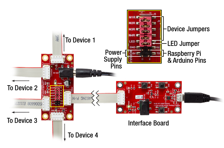
複数のElliptecデバイスの制御は、バス分配器ELLBを使用するか、1本のリボンケーブルに複数のコネクタを接続することで可能になります。1個のバス分配器で最大4台までのElliptecデバイスを接続できます。さらに分配器をデイジーチェーン接続することで、最大16台までのデバイスを接続することができます。このバスの制御は、Elliptecソフトウェアが動作しているPCとのインターフェイスボード(下記のセットに付属)を介した接続、Arduino®2またはRaspberry Pi®3ボードとの接続、お手持ちの制御ボードとのコネクターピンを介した接続の3つの方法のうちのいずれかを用いることで可能になります。そのほか、1本のリボンケーブルに最大16台のデバイスを接続することもできます。この接続では、インターフェイスボードを用いて各デバイスを同時に制御するか、またはElliptecソフトウェアでデバイスを選択して制御することができます。複数のデバイスをリボンケーブルに接続する方法についてはマニュアルを、カスタム接続するときのピン配列については「ピン配列」タブをご覧ください。
応用例
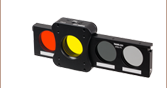
マルチポジションスライダは、フィルターチェンジャとして使用するのに適しています。ELL6についてはシャッタとしてのご使用もお勧めいたします。キャリッジにはSM05またはSM1の内ネジ付きポート(深さ3.5 mm)が付いています。構造体であるPCBには4つの#4-40タップ穴があり、これを利用してスライダをポスト取付け用アダプタELLA1(下記参照)を用いて取付けることも、また
- PicoflexはMolex社の登録商標です。
- ArduinoはArduino社の登録商標です。
- Raspberry PiはRaspberry Pi財団の登録商標です。
仕様
性能仕様は、マルチポジションスライダを「使用方法」タブにおいて推奨している方法で取り付けた場合の値です。
| Item # | ELL12(K) | ELL6(K) | ELL9(K) | |
|---|---|---|---|---|
| Performance | ||||
| Switching Time between Adjacent Positions | Unloaded Carriage on Slider | 350 to 400 ms | 180 to 270 ms | 450 to 500 ms |
| Loaded Carriage on Slider | < 600 ms (150 g Load) | < 600 ms (100 g Load) | < 700 ms (150 g Load) |
|
| Thread Type of Ports in Carriage | Internal SM05 (0.535"-40)a Threads, 3.5 mm Deep | Internal SM1 (1.035"-40)a Threads, 3.5 mm Deep | ||
| Number of Threaded Ports in Carriage | Six | Two | Four | |
| Travel | 95 mm (3.74") | 31 mm (1.22") | 93 mm (3.66") | |
| Positioning Repeatabilityb | < 100 µm (30 µm Typical) | |||
| Maximum Total Load (Vertically Mounted)c | 150 g (5.29 oz) | |||
| Minimum Lifetimed | 3.3 Million Switching Operations or 100 km Total Travel | |||
| Electrical | ||||
| DC Voltage Input | 4.5 to 5.5 V | |||
| Typical Current Consumption | During Movement | < 1200 mA | < 600 mA | < 1200 mA |
| During Standby | 38 mA | |||
| During Search for Resonant Frequenciese | 1.2 A | |||
| Communications | ||||
| Busf | Multi-Drop 3.3 V/5 V TTL RS232 | |||
| Connector on Multi-Position Slider Board | Picoflex® | |||
| Connectors on Interface Board | Picoflex® Micro-B USB 5 VDC Power: [For Plug with Ø5.5 mm OD (Ground) and Ø2.1 mm ID (+5 V)] | |||
| Speed | 9600 baud/s | |||
| Data Lengthg | 8 bit | |||
| Protocol Data Format | ASCII HEX | |||
| Module Address and Command Format | Mnemonic Character | |||
| 8-Conductor Ribbon Cable Length | Supplied: 0.250 m; Max: 3 m | |||
| Mechanical | ||||
| Dimensions of the Slider (At End Stops)h | 143.5 mm x 77.7 mm x 14.2 mm (5.65" x 3.06" x 0.56") | 80.5 mm x 77.7 mm x 14.9 mm (3.16" x 3.06" x 0.59") | 143.5 mm x 77.7 mm x 14.9 mm (5.65" x 3.06" x 0.59") | |
| Dimensions of the Interface Board | 32.0 mm x 66.0 mm x 12.5 mm (1.26" x 2.60" x 0.49") | |||
| Weight (Slider) | 78.5 g (2.77 oz) | 44.0 g (1.55 oz) | 70.0 g (2.47 oz) | |
| Weight (Interface Board) | 10.3 g (0.36 oz) | |||
| Environmental Operating Conditions | ||||
| Temperature Range | 15 to 40 °C | |||
| Maximum Relative Humidity (Non-Condensing) | < 80% at 31 °C | |||
| Maximum Altitude | 2000 m | |||
| ELL12 & ELL9 Connector J2 Pinouta,b | ||
|---|---|---|
| Pin | Type | Function |
| 1 | PWR | Ground |
| 2 | OUT | OTDX - Open Drain Transmit 3.3 V TTL RS232 |
| 3 | IN | RX Receive 3.3 V TTL RS232 |
| 4 | OUT | In Motion, Open Drain Active Low Max 5 mA |
| 5 | IN | JOG/Mode, Active Low Max 5 V |
| 6 | IN | BW Backward, Active Low Max 5 V |
| 7 | IN | FW Forward, Active Low Max 5 V |
| 8 | PWR | VCC +5 V ± 10%; 1200 mA |

Click to Enlarge
デュアルポジションスライダELL12とELL9のPCB上のPicoflex®コネクタのピン配列図。
左上はデュアルポジションスライダのボードの一部。コネクタ上の極性を示すマークが、
8ピンコネクタ付きケーブルの赤いワイヤに近くなるように接続してください。
| ELL6 Connector J2 Pinouta,b | ||
|---|---|---|
| Pin | Type | Function |
| 1 | PWR | Ground |
| 2 | OUT | OTDX - Open Drain Transmit 3.3 V TTL RS232 |
| 3 | IN | RX Receive 3.3 V TTL RS232 |
| 4 | OUT | In Motion, Open Drain Active Low Max 5 mA |
| 5 | IN | JOG/Mode = Normal/Test Demo, Active Low Max 5 V |
| 6 | IN | BW Backward, Active Low Max 5 V |
| 7 | IN | FW Forward, Active Low Max 5 V |
| 8 | PWR | VCC +5 V ± 10%; 600 mA |
Click to Enlarge
デュアルポジションスライダELL6のPCB上のPicoflex®コネクタのピン配列図。
左上はデュアルポジションスライダELL6のボードの一部。コネクタ上の極性を示すマークが、
8ピンコネクタ付きケーブルの赤いワイヤに近くなるように接続してください。
| ELLB Connector J1, J2, J3, and J4 Pinouta,b | ||
|---|---|---|
| Pin | Type | Function |
| 1 | PWR | Ground |
| 2 | OUT | OTDX - Open Drain Transmit 3.3 V TTL RS232 |
| 3 | IN | RX Receive 3.3 V TTL RS232 |
| 4 | OUT | In Motion, Open Drain Active Low Max 5 mA |
| 5 | IN | Not Connected |
| 6 | IN | Not Connected |
| 7 | IN | Not Connected |
| 8 | PWR | VCC +5 V ± 10%; 800 mA per Connected Device |

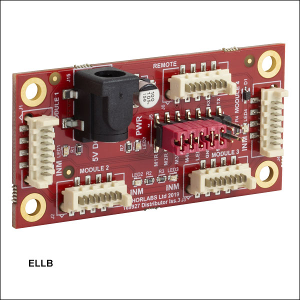
Click to Enlarge
バス分配器ELLB上のPicoflex® コネクタのピン配列図。
左上はELLBの簡略図です。コネクタ上の極性を示すマークが、
8ピンコネクタ付きケーブルの赤いワイヤに近くなるように
接続してください。
使用上の注意
こちらのタブでは、デュアルおよび4ポジションスライダの取り扱いや、取付け方法、操作方法に関する情報をご紹介しています。
目次
Click to Enlarge
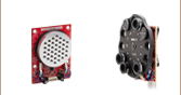
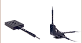
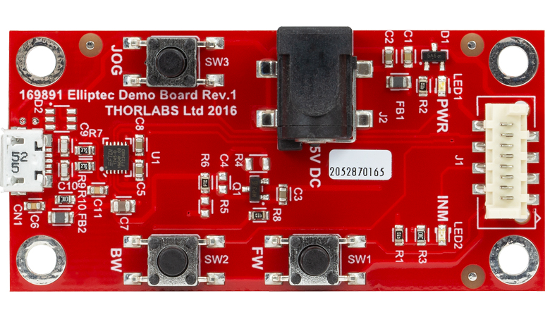
図2 インターフェイスボード
Click to Enlarge
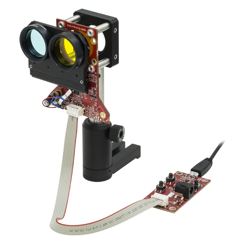
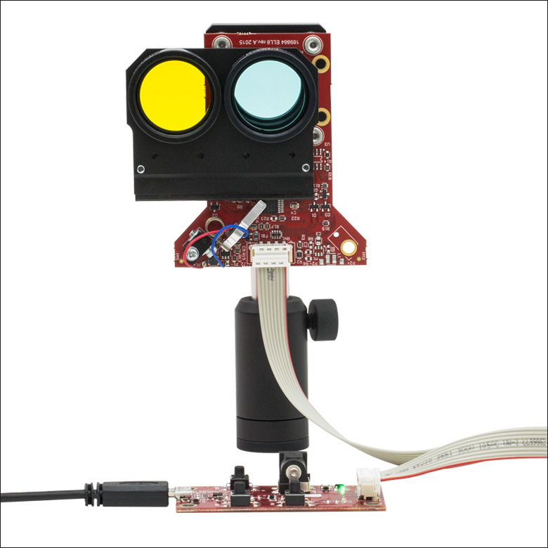
図4 ガラスフィルタを装着し30 mmケージシステムを取り付けたデュアルポジションスライダELL6K
Click to Enlarge
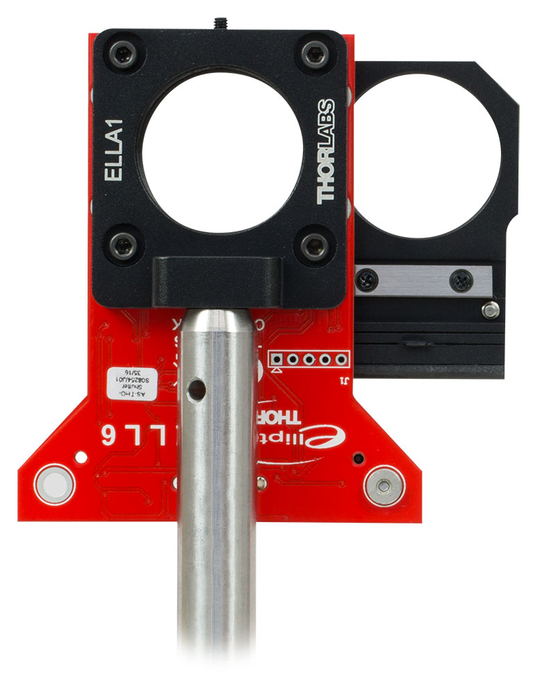
図3ガラスフィルタを装着しアダプタELLA1を使用したデュアルポジションスライダELL6K
取扱い
当社のスライダとインターフェイスボードは、一般的な取り扱いに対しては堅牢に作られています。図1はELL9Kのセットを組み立てた状態を示しており、主要部の名称等も記載されています。図2はインターフェイスボードの写真です。動作の信頼性を確保するために、モータが接触する面には油、汚れ、埃が付かないようにしてください。デュアルおよび4ポジションスライダを取り扱う際に手袋の着用までは必要ありませんが、汚れが付着しないようモータが接触する面には触れないでください。モータが接触する面が汚れた場合には、KW32や同様の防塵紙を使用し、イソプロピルアルコールまたはミネラルスピリット(ホワイトスピリット)で汚れを拭き取ってください。アセトンはキャリッジのプラスチック製エッジを損傷しますので使用しないでください。
こちらのスライダはオープンフレームですが、8 kVまでの静電気放電に耐えられます。しかしESDに対する予防策は講じてください。放電が発生すると、意図しないキャリッジの動きを誘発する電気信号が生じる可能性があります。また、PCB構造に500 gを超える荷重は加えないでください。過大な荷重を加えるとPCBが曲がり、スライダの性能が低下する可能性があります。
取付方法
マルチポジションスライダは、一定の条件下であれば、スライダを垂直(直立状態)あるいは水平(寝かせた状態)に取り付けて動作させることができます。スライダを垂直方向に取り付ける場合、キャリッジが上下ではなく横方向に移動するように取り付けてください。上下方向では重力の影響により移動可能な最大荷重が大幅に減少するためです。スライダを垂直方向に取り付ける場合、モータはキャリッジの上下どちらにも配置可能です。しかし、お勧めは図3~7のようにモータがキャリッジの下にくる配置です。こうすることで、動作中にキャリッジに取り付けた光学素子表面に埃や粒子が付着する可能性が低くなります。スライダを水平方向に取り付ける際には、PCBが曲がらないようにしてください。何れの取付け方法においても、スライダの可動部に接触するものがないことをご確認ください。
スライダの取り付け方にはいくつかの方法があります。ポスト取付け用アダプタELLA1(下記参照)は、PCBの裏面に直接固定できます。図3に示すように、このアダプタを使用するとスライダをØ12 mm~Ø12.7 mm(Ø1/2インチ)ポストに取り付けられます。ELLA1はコンパクトなため、最小限のスペースでスライダを前後に配置することもできます(下の写真参照)。また、このアダプタは当社の30 mmケージシステム部品やレンズチューブなどのSM1ネジ付き部品にも取り付けが可能です。ELLA1の代わりに、30 mmケージシステム部品を直接スライダに取り付けることもできます。その例は図4でご覧いただけますが、この例ではケージプレートCP33(/M)、4本のER1ロッド、Ø12.7 mm(Ø1/2インチ)ポスト、そしてポストホルダーマウントを使用してELL6Kのアセンブリを支持しています。
負荷
最大許容荷重の150 gは、キャリッジが搭載する荷重を示しており、スライダの重量は含まれていません。例えば、無負荷状態のスライダELL6の重量は約22 gです。搭載する部品に対する最大許容荷重は150 gなので、スライダと搭載部品を合わせた最大許容荷重は172 gになります。スライダはどちらも30 mmケージシステム部品に対応するように設計されています。
電力の供給
インターフェイスボードを使用する場合
モータの動作には超音波周波数の電圧信号が必要ですが、このステージはDC電圧信号をインターフェイスボードに印加するだけで駆動することができます。ボード上の電子回路により、入力されたDC信号は必要な共振周波数の正弦波信号に変換されます。
ELL6には1つのモータ、ELL12およびELL9には2つのモータが付いています。ELL6はモータが1つで要求電力が小さいため、インターフェイスボード上のMicro-B USBコネクタから電力を供給することができます。 5 V電源はELL6Kのセットには含まれていません。2つのモータ付きのスライダを動作させるには5 V電源が必要で、ELL12KおよびELL9Kのセットには1個付属しています。
インターフェイスボード上のMicro-B USBコネクタを使用してELL6に電力を供給するメリットの1つは、PCを使用してスライダの制御と電力供給が同時にできることです。一般にノートPCでもデュアルポジションスライダELL6の位置を切り替えるのに必要な電流を供給できます。しかしPCによっては、後の「共振周波数」で説明する最適共振周波数を検出する際に、必要な1.2 Aを供給できない可能性があります。そのような状況で最適共振周波数を検出する場合は、ノートPCが供給する電力を補完するために、必要な電流を供給できる別の電源を使用する必要があります。
ELL12または ELL9とインターフェイスボードを含むセットアップの場合には、電源は5 VDC電源ソケットより供給します。Micro-B USBコネクタでは両方のモータを駆動するのに十分な電力を供給できないため、このコネクタはスライダのPC制御用にのみ使用されます。
インターフェイスボードを使用しない場合
スライダをインターフェイスボード無しで組み込む場合、電源との接続にはPicoflex®コネクタのピンを使用します。このコネクタのピン配列は「ピン配列」タブに記載されています。スライダの電力供給やアドレス指定に関する詳細は、それぞれマニュアルと通信プロトコルマニュアルをご参照ください。
モータの動作原理
Elliptecモータはスライダ上のキャリッジの位置を移動させますが、移動方向はモータのピエゾ素子を駆動する超音波周波数によって決定されます。モータにはキャリッジを前方に押し出すように作用する超音波共振周波数と、キャリッジを後方に引っ張るように作用する超音波共振周波数があります。モータを一方の共振周波数で駆動すると、モータの先端は小さな楕円形の軌跡を時計回りに連続的に描きます。もう一方の共振周波数で駆動すると、先端は同じ軌跡を反時計回りに描きます。どちらの共振周波数も100 kHz近辺です。モータ先端の総変位量は、駆動する機械的負荷とピエゾ素子に供給される電圧によります。負荷を付けずに最大電圧5 Vの共振周波数で駆動すると、モータの先端は数μm以下の伸縮をして楕円を描きます。詳細については「Elliptec®モータ」のタブと、モータの動作原理を説明した動画をご覧ください。
共振周波数
工場出荷時の初期設定では、スライダが最良の性能を発揮する共振周波数を検出する作業を、電源投入時に行うように設定されています。このプロセスの間、スライダは前方位置と後方位置を往復します。この校正作業を終了すると、スライダは後方位置にセットされます。起動時のこの動作を止めたい場合には、シリアルポートを使用して電源投入時の周波数を初期化することで、校正プロセスを無効にすることができます。最適共振周波数の検出はいつでも実施可能ですが、適切な性能を維持するために、荷重や周囲温度が変化したときには、新たにこの検出作業を実施することをお勧めします。詳細についてはマニュアルのセクション4.4をご覧ください。
スライダの操作方法
当社のスライダは連続動作用には設計されていないことにご留意ください。一般的な用途においてはデューティ比40%以下での動作をお勧めいたします。また、デューティ比60%以上での動作は数秒以下に制限する必要があります。
スライダのキャリッジの動作は、インターフェイスボードのボタン操作、Elliptec®ソフトウェアパッケージ(ダウンロード可能)を介したPC制御、またはスライダーボードのデジタル信号線に単純な信号を入力することで制御できます。 一定の駆動電力に対して速度は直線的に変化し、それによりモータは数マイクロ秒で加速、減速ができます。
インターフェイスボードはElliptecソフトウェアとスライダを接続するアクセサリとして使用することもできます。その場合、インターフェイスボードのボタンを押したとき、キャリッジの位置変化はすべてソフトウェアによって記録されます。またインターフェイスボードが接続されていても、ソフトウェアは独立してキャリッジを制御することができます。インターフェイスボードのボタンは図2でご覧いただけます。
複数のElliptecデバイスは、バス分配器ELLBを使用するか、複数のコネクタを1本のリボンケーブルに接続することで制御できます。1個のバス分配器で最大4台までのElliptecデバイスを接続できます。さらに分配器をデイジーチェーン接続することで、最大16台までのデバイスを接続することができます。このバスは、Elliptecソフトウェアが動作しているPCとのインターフェイスボード(下記のセットに付属)を介した接続、Arduino®またはRaspberry Pi®ボードとの接続、お手持ちの制御ボードとのコネクターピンを介した接続の3つの方法のうちのいずれかを用いることで制御できます。なお、インターフェイスボードをご使用の場合、ボード上のボタンは無効になります。または、1本のリボンケーブルに最大16台のデバイスを接続することもできます。各デバイスはインターフェイスボードで同時に制御することも、Elliptecソフトウェアでデバイスを選択して制御することもできます。複数のデバイスをリボンケーブルに接続する方法についてはマニュアルを、カスタム接続するときのピン配列については「ピン配列 」タブをご覧ください。ソフトウェアで各デバイスを個別にアドレス指定する方法については、通信プロトコルマニュアルをご参照ください。ソフトウェアと付属文書は「ソフトウェア」タブからダウンロードいただけます。
図5~7と「概要」タブ内の動画では、インターフェイスボードを使用したデュアルポジションスライダELL6の動作がご覧いただけます。図5のようにインターフェイスボードの「FW」と書かれているボタンを押すと、スライダは前方位置に送られます。インターフェイスボードの「BW」と書かれているボタンを押すと、スライダはホーム位置に戻ります。
インターフェイスボードを使用して4ポジションスライダELL9によるキャリッジ位置の制御を行う場合は、JOGボタンも使用します。スライダが前方を向いて垂直に置かれ、モータが移動マウントの下に位置している場合、JOGボタンを押しながらFWボタンを押すと、キャリッジは観察者から見て1つ右の位置に移動します。JOGボタンを押しながらBWボタンを押すと、キャリッジは観察者から見て1つ左の位置に移動します。言い方を変えると、「仕様」タブの1番下の図の通り、前述の方法でキャリッジの位置はインクリメントされ、後述の方法でキャリッジの位置がディクリメントされます。


スライダのセットELL12K、ELL9K

各セットには下記が含まれます。
- スライダ
- インターフェイスボード
- Micro-B to A-Type USBケーブル
- 8芯 28AWGリボンケーブル
- 5 V電源、日本国内用電源プラグ付き
PC用ソフトウェアはマニュアル、通信プロトコルマニュアル、そのほかの文書とともにダウンロード可能です。
スライダのセットELL6K
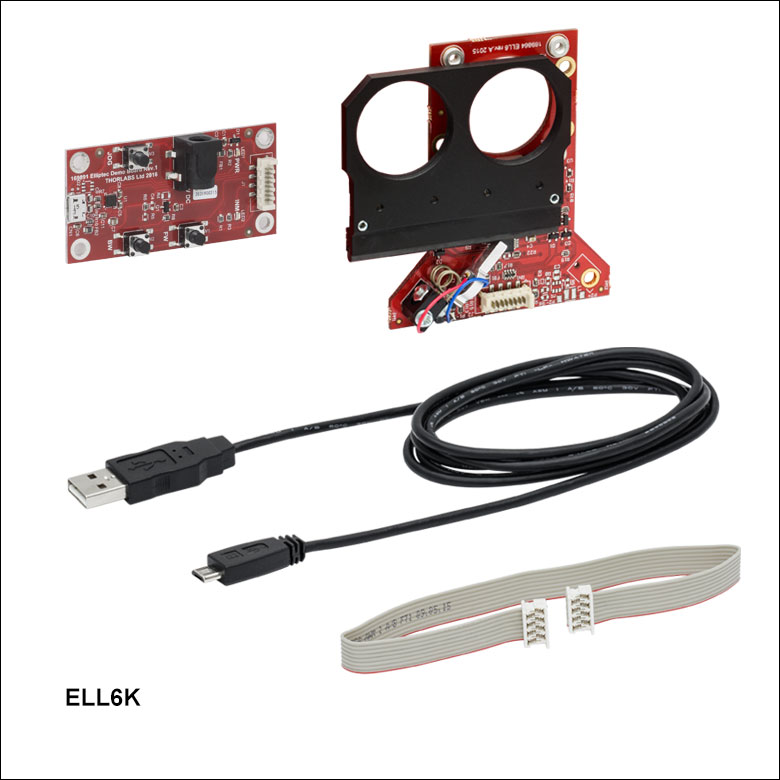
Click to Enlarge
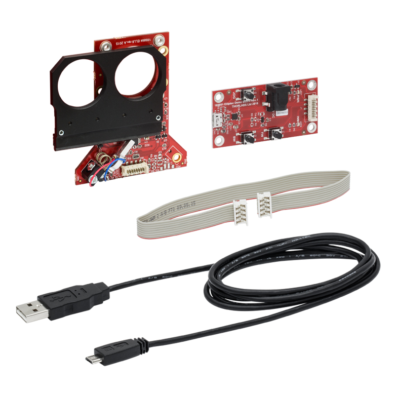
ELL6Kのセット内容
各セットには下記が含まれます。
- スライダ
- インターフェイスボード
- Micro-B to A-Type USBケーブル
- 8芯 28AWGリボンケーブル
PC用ソフトウェアはマニュアル、通信プロトコルマニュアル、そのほかの文書とともにダウンロード可能です。
Click to Enlarge
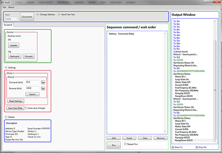
Elliptec共振ピエゾモータ用コントロールソフトウェアのGUI
Elliptec®共振ピエゾモータ用ソフトウェア
Elliptec®共振ピエゾモータをベースとするすべてのデバイスは、直感的なGUIを特長とするElliptecシステムソフトウェアで制御可能です。C#フォーマットのソースコードがダウンロード可能なソフトウェア一式に含まれており、あらゆる言語でカスタム仕様のアプリケーションを作成することができます。右の図はGUIのスクリーンショットです。また下のボタンをクリックするとダウンロードのページがご覧いただけます。
コマンドはGUI画面のSequencer command / wait orderに入力します。デバイスに送るコマンドシーケンスの例として、「Afw」はアドレス「A」のスライダを前方位置に移動させ、「Abw」はアドレス「A」のスライダを後方位置に移動させます。コマンド「As1」は、現在の動作条件下においてアドレス「A」にあるモータに適した共振周波数を特定するための検出作業を実施します。
ソフトウェア
バージョン 1.6.3
操作が簡単なGUI付きのElliptecシステムソフトウェアが含まれます。Elliptecソフトウェアパッケージ用通信コマンドを説明した文書もダウンロード可能です。
| SM05 Threading: Ø1/2" Lens Tubes, 16 mm Cage Systems | |||
|---|---|---|---|
| External Thread, 0.535"-40.0 UNS-2A | Internal Thread, 0.535"-40.0 UNS-2B | ||
| Max Major Diameter | 0.5340" | Min Major Diameter | 0.5350" |
| Min Major Diameter | 0.5289" | Min Pitch Diameter | 0.5188" |
| Max Pitch Diameter | 0.5178" | Max Pitch Diameter | 0.5230" |
| Min Pitch Diameter | 0.5146" | Min Minor Diameter (and 83.3% of Thread) | 0.508" |
| Max Minor Diameter | 0.5069" | Max Minor Diameter (and 64.9% of Thread) | 0.514" |
| RMS Threading: Objective, Scan, and Tube Lenses | |||
|---|---|---|---|
| External Thread, 0.800"-36.0 UNS-2A | Internal Thread, 0.800"-36.0 UNS-2B | ||
| Max Major Diameter | 0.7989" | Min Major Diameter | 0.8000" |
| Min Major Diameter | 0.7934" | Min Pitch Diameter | 0.7820" |
| Max Pitch Diameter | 0.7809" | Max Pitch Diameter | 0.7866" |
| Min Pitch Diameter | 0.7774" | Min Minor Diameter (and 83.3% of Thread) | 0.770" |
| Max Minor Diameter | 0.7688" | Max Minor Diameter (and 64.9% of Thread) | 0.777" |
| C-Mount Threading: Machine Vision Lenses, CCD/CMOS Cameras | |||
|---|---|---|---|
| External Thread, 1.000"-32.0 UN-2A | Internal Thread, 1.000"-32.0 UN-2B | ||
| Max Major Diameter | 0.9989" | Min Major Diameter | 1.0000" |
| Min Major Diameter | 0.9929" | Min Pitch Diameter | 0.9797" |
| Max Pitch Diameter | 0.9786" | Max Pitch Diameter | 0.9846" |
| Min Pitch Diameter | 0.9748" | Min Minor Diameter (and 83.3% of Thread) | 0.966" |
| Max Minor Diameter | 0.9651" | Max Minor Diameter (and 64.9% of Thread) | 0.974" |
| SM1 Threading: Ø1" Lens Tubes, 30 mm Cage Systems | |||
|---|---|---|---|
| External Thread, 1.035"-40.0 UNS-2A | Internal Thread, 1.035"-40.0 UNS-2B | ||
| Max Major Diameter | 1.0339" | Min Major Diameter | 1.0350" |
| Min Major Diameter | 1.0288" | Min Pitch Diameter | 1.0188" |
| Max Pitch Diameter | 1.0177" | Max Pitch Diameter | 1.0234" |
| Min Pitch Diameter | 1.0142" | Min Minor Diameter (and 83.3% of Thread) | 1.008" |
| Max Minor Diameter | 1.0068" | Max Minor Diameter (and 64.9% of Thread) | 1.014" |
| SM30 Threading: Ø30 mm Lens Tubes | |||
|---|---|---|---|
| External Thread, M30.5 x 0.5 – 6H/6g | Internal Thread, M30.5 x 0.5 – 6H/6g | ||
| Max Major Diameter | 30.480 mm | Min Major Diameter | 30.500 mm |
| Min Major Diameter | 30.371 mm | Min Pitch Diameter | 30.175 mm |
| Max Pitch Diameter | 30.155 mm | Max Pitch Diameter | 30.302 mm |
| Min Pitch Diameter | 30.059 mm | Min Minor Diameter (and 83.3% of Thread) | 29.959 mm |
| Max Minor Diameter | 29.938 mm | Max Minor Diameter (and 64.9% of Thread) | 30.094 mm |
| SM1.5 Threading: Ø1.5" Lens Tubes | |||
|---|---|---|---|
| External Thread, 1.535"-40 UNS-2A | Internal Thread, 1.535"-40 UNS-2B | ||
| Max Major Diameter | 1.5339" | Min Major Diameter | 1.535" |
| Min Major Diameter | 1.5288" | Min Pitch Diameter | 1.5188" |
| Max Pitch Diameter | 1.5177" | Max Pitch Diameter | 1.5236" |
| Min Pitch Diameter | 1.5140" | Min Minor Diameter (and 83.3% of Thread) | 1.508" |
| Max Minor Diameter | 1.5068" | Max Minor Diameter (and 64.9% of Thread) | 1.514" |
| SM2 Threading: Ø2" Lens Tubes, 60 mm Cage Systems | |||
|---|---|---|---|
| External Thread, 2.035"-40.0 UNS-2A | Internal Thread, 2.035"-40.0 UNS-2B | ||
| Max Major Diameter | 2.0338" | Min Major Diameter | 2.0350" |
| Min Major Diameter | 2.0287" | Min Pitch Diameter | 2.0188" |
| Max Pitch Diameter | 2.0176" | Max Pitch Diameter | 2.0239" |
| Min Pitch Diameter | 2.0137" | Min Minor Diameter (and 83.3% of Thread) | 2.008" |
| Max Minor Diameter | 2.0067" | Max Minor Diameter (and 64.9% of Thread) | 2.014" |
| SM3 Threading: Ø3" Lens Tubes | |||
|---|---|---|---|
| External Thread, 3.035"-40.0 UNS-2A | Internal Thread, 3.035"-40.0 UNS-2B | ||
| Max Major Diameter | 3.0337" | Min Major Diameter | 3.0350" |
| Min Major Diameter | 3.0286" | Min Pitch Diameter | 3.0188" |
| Max Pitch Diameter | 3.0175" | Max Pitch Diameter | 3.0242" |
| Min Pitch Diameter | 3.0133" | Min Minor Diameter (and 83.3% of Thread) | 3.008" |
| Max Minor Diameter | 3.0066" | Max Minor Diameter (and 64.9% of Thread) | 3.014" |
| SM4 Threading: Ø4" Lens Tubes | |||
|---|---|---|---|
| External Thread, 4.035"-40 UNS-2A | Internal Thread, 4.035"-40.0 UNS-2B | ||
| Max Major Diameter | 4.0337" | Min Major Diameter | 4.0350" |
| Min Major Diameter | 4.0286" | Min Pitch Diameter | 4.0188" |
| Max Pitch Diameter | 4.0175" | Max Pitch Diameter | 4.0245" |
| Min Pitch Diameter | 4.0131" | Min Minor Diameter (and 83.3% of Thread) | 4.008" |
| Max Minor Diameter | 4.0066" | Max Minor Diameter (and 64.9% of Thread) | 4.014" |
Click to Enlarge
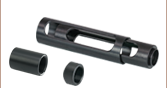
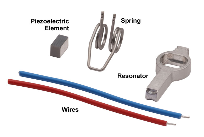
Elliptecモータの部品
Click to Enlarge
Elliptec共振ピエゾモータ
Elliptec®共振ピエゾモータ
右に示した当社のElliptec®共振ピエゾモータの質量は1.2 gと軽量で、共振器筐体の寸法はバネを除いて8 mm×4 mm×20 mmとコンパクトです。
モータの部品
モータを構成する部品は右端の写真でご覧いただけます。ピエゾ素子はアルミニウム製の共振器内に圧入されています。共振器はその先端が必要とされる楕円形の動作をし、駆動されるモジュールと適切に接触するよう精密設計・精密加工がなされています。バネの自由端側は共振器筐体に組み込まれています。ピエゾ素子の上部ならびに底部にはんだ付けされているワイヤには、ピエゾ素子を超音波周波数で振動させるための電圧信号を供給します。
モータをシステム内に組み込むときは、バネの開ループ側を駆動される対象物に対して動かない頑丈な面に固定し、共振器の先端は対象物に接触させます。バネの目的は共振器の先端と駆動対象物との接触を一定に維持することです。また移動方向はピエゾ素子を駆動する2つの共振周波数によって決まります。
楕円形の動作と一般的なモータとの比較
このモータは、2つの共振周波数のうちのいずれかで駆動することにより動作します。超音波周波数で振動する電圧信号がピエゾ素子に印加されると、ピエゾ素子はその電圧信号の周波数に合わせて1 µm以下のレベルで伸長し、また元の寸法にまで収縮します。ピエゾ素子の寸法がこのように高速のサイクルで変化すると、アルミニウム製の共振器に振動が発生します。この振動が筐体の共振周波数のうちの一方の周波数で生じているときに、モータの先端に押す動作が発生します。もう一方の共振周波数で振動するときは、引っ張る動作が発生します。
動画に示されているように、モータが共振状態で動作している時にはその先端が楕円形の軌跡を描き、それによってこの引っ張る動作と押す動作が発生します。また、楕円の回る方向は選択された共振周波数によって決まります。モータの先端は楕円の半分を描くときは伸び、残りの半分を描くときは縮みます。モータが対象物を押すときは、先端が伸びるときに先端と対象物が接触し、縮むときには接触しません。モータが対象物を引っ張るときは、逆の動作をします。モータ先端の総変位量は、駆動する機械的負荷とピエゾ素子に供給される電圧の両方に依存します。駆動電圧のピーク値が5 Vのとき、最大変位量は数µmまで大きくなる可能性があります。
このモータはDCモータあるいは電磁ステッピングモータと同じように動作しますが、従来のモータの様々な欠点がありません。従来の電磁モータを停止させるには慣性に伴う遅延を克服する必要がありますが、非常に動的特性に優れたElliptecモータでは数マイクロ秒で停止できます。ギアがないため、バックラッシュも発生しません。磁石も無いため、電磁障害に敏感な用途にも使用できます。駆動される対象物の動きは連続的でスムーズです。駆動対象物を動かすにはモータの先端をそれと接触させる必要があるため、モータには摩擦ブレーキという安全機能が備わっています。プラスチック面に接している場合は、モータは静かに動作します。
製品組み込み(OEM)用途のためには、低コストに抑えるためモータを大量生産し、低価格のアナログ電子回路で駆動することもできます。マイクロプロセッサやソフトウェアは必要ありませんが、対応は可能です。
| Posted Comments: | |
user
(posted 2024-01-23 21:25:36.603) Hi,
I purchased a couple of rotation mounts (ELL14K and ELL18) for use with a high power femtosecond laser. I would like to have a protective cage to avoid damaging the electronic components and scattering of the laser. Do you have an example of a 3D printable design for this purpose?
Best regards. Bin Yang
(posted 2023-12-29 07:35:01.76) I am trying to use LabView to control ELL9K. Can you please send me the example VI for that. Thank you! do'neill
(posted 2024-01-04 08:46:18.0) Thank you for your enquiry. I will reach out to you directly to provide this example VI. Kirill Mitrofanov
(posted 2023-12-20 12:42:58.02) I use ELL6 in my lab and at some point I got the following issue: the motor moves only half-distance and stops there. It looks like it tries to move more, but something stops it from doing that.
Is there any solution for that? do'neill
(posted 2024-01-03 06:22:38.0) Thank you for your feedback and I am sorry to hear this. Usually this can be fixed by performing a frequency search, as operating too far from this optimum frequency can cause it to move slowly or not reach the desired location. The other thing I would suggest is to clean the rail with IPA as this can be another reason it does not reach the desired location. I will reach out to you directly to further help troubleshoot this with you. Fabian C
(posted 2023-12-15 16:19:36.24) Hi
I currently have an ELL20K/M and ELL14K/M connected through the ELLB bus, and i would like to control them both with python. I have downloaded the example EEL17_pythonnet.py, but the problem is that the program moves both of them simultaneously. How can i avoid this to have independent control? Thanks do'neill
(posted 2024-01-02 10:46:56.0) Thank you for your enquiry. This is possible with some editing of the example. As long as the devices are on different addresses, they can be controlled independently. I will reach out to you directly to help you through this. user
(posted 2023-12-07 13:29:49.057) Hi, i want to control several devices using the ELLB bus and the software ELLO. When i scan the port, it recognized one device but nothing else shows. How can i send instructions to the different devices now? (this used to work when each device was connected separately, without using the ELLB)
Thanks Andreas B
(posted 2023-11-06 11:06:29.717) Hi, We bought an Elliptec multi-positioner filter mount. It worked fine to start with but now suddenly gives "Sensor error". Any thought on how to adress this issue? do'neill
(posted 2023-11-13 04:45:37.0) Response from Daniel at Thorlabs. This is caused by the motor not reaching the correct position or not being able to sense the starting position. One of the first things you can do is frequency scan the device and gently and carefully clean the rail with IPA. I will reach out to you directly to troubleshoot this with you. Alex B
(posted 2023-09-17 23:13:49.947) Hello, I would also like to use the LabVIEW drivers. Can you send them to me too? Thanks do'neill
(posted 2023-09-19 07:21:08.0) Response from Daniel at Thorlabs. We do not have LabVIEW wrappers or drivers for the Elliptec stages but the .NET DLLs that are included with ELLO install. I will reach out to you with an example VI to get you started. Stephan Troyer
(posted 2023-08-04 12:43:47.94) In the ELLB's manual it could be useful to note that the USB RX/TX pins work as UART. Many things are quite obvious in hindsight, but when having issues (for example since the board is not responding any command when no motor is connected or when receiving garbage from a floating), that confirmation would be useful as a confirmation.
In addition, it is noteworthy, that TX/RX is reversed compared to common labelling. Usually, TX of one device gets connected to RX of the other device. On the distributor port, one has to connect the microcontroller's TX pin to the distributor board's TX pin. The naming gets slightly inconsistent since the board's TX pin is internally connected to the RX pin of the MOLEX connector.
Since it's not only the manual but also the PCB where the TX/RX labelling is printed, I would at least clearly specify the mix up it in the manual.
Best,
Stephan Troyer fguzman
(posted 2023-08-08 05:16:54.0) Thanks for your feedback. We have taken note on this and we will revise your comments on this. Ralf Wunderlich
(posted 2023-06-13 17:22:09.523) Hi,
I am using your ELL6K in a box that also houses an APD. When I connect the ELL6K to the USB port (providing power to the device), I have a significant increase in the APD's count rate? Most likely the ELL6K is using optical position feedback from an LED or something. Can you specify the wavelength?
Kind regards do'neill
(posted 2023-06-21 06:55:39.0) Response from Daniel at Thorlabs. The home sensor of the device uses a 950nm led which can leak light. This should be taken into consideration for environments that are sensitive to light sources at and around this wavelength. Kai M
(posted 2023-05-31 18:12:13.823) Hi, I'm using ELLB to control multiple ELL14. How do I set multiple devices properly in ELLO software? Could you also share Labview VI for controlling multiple devices using ELLB? Thank you! do'neill
(posted 2023-06-02 12:32:52.0) Response from Daniel at Thorlabs. I will reach out to you directly to provide these VIs and help you with your application. user
(posted 2023-04-11 18:46:31.413) Do you happen to have an example VI (LabView) written for this device available? If yes, could you please share where we can locate it? Many thanks! JReeder
(posted 2023-04-12 03:20:59.0) Thank you for your enquiry. I have reached out to you directly to provide an example LabVIEW VI for this product. user
(posted 2023-01-19 16:39:36.737) Hi, you state that the ELL series sliders should not be mounted such that the carriage moves vertically, only horizontally. Will they work if they are mounted "upside down" i.e. such that the carriage moves horizontally but the motor being above the carriage? JReeder
(posted 2023-01-20 11:52:00.0) Thank you for your enquiry. This is not something we have tested extensively, but we believe that this should work. It is worth noting though that the ELLx devices produce some fine particulates due to the friction mechanism which in this orientation can drop down onto the optics. Takahiro Deguchi
(posted 2023-01-19 14:29:55.29) Dear Thorlabs
We purchased ELL9K and installed in our single molecule microscope. Recently, we found out that ELL9 (not the interface board) emits some kind of light so that it was giving a high amount of background to our camera images. By adding short-pass 750 filter in front of camera, we could block the background signal completely. Do you know if there is any LED or a light source in IR on ELL9?
I just wanted to know if you are aware of this or if it is specified somewhere. Thank you.
Best regards
Takahiro DEGUCHI JReeder
(posted 2023-01-20 05:35:24.0) Thank you for your enquiry. All of our ELLx devices use a photo interrupter for the homing and encoder, it emits at 950 nm and the detector part is sensitive from 700 to 1200 nm. Due to this light source, applications that are very sensitive to 950 nm light should not use the ELLx devices or should take precautions to protect their application from this light. Some ELL devices may also struggle to home if they are exposed to a large amount of light in the 700-1200 nm range. user
(posted 2023-01-08 01:41:06.937) Is there any example VI (labview) written for this device? If so, where can we find it? Thank you! do'neill
(posted 2023-01-10 11:25:04.0) Response from Daniel at Thorlabs. Thank you for your inquiry. We will get in touch with you directly. Yannic Staechelin
(posted 2022-12-16 09:11:57.787) I use your ELL9 in an optical setup, where it changes its position every five seconds for some hours. In the beginning it works just fine, but after some time a "Sensor Error" occurs repeatedly. Is there anything I can do to avoid the "Sensor Error"? cwright
(posted 2022-12-16 10:24:26.0) Response from Charles at Thorlabs: Thank you for your query. These sensors are small IR LEDs paired with photodiodes. When paddles on the back of the moving world block the light from hitting the photodiode, the position of the stage is updated. Sensor errors are usually the result of ambient light/laser light getting into the photodiode, dust obscuring the photodiode, or a paddle not sufficiently blocking the light. I will reach out to you to help resolve this. Lavonne Dettmers
(posted 2022-11-08 12:27:05.457) Could you please allow the ELL9 to be generated on a RoHS compliance certificate?
Thanks,
Lavonne Dettmers cwright
(posted 2022-11-14 05:20:22.0) Response from Charles at Thorlabs: Thank you for your query. A member of technical support will look into this and reach out to you by email. Tao Ding
(posted 2022-11-04 13:26:05.6) can it be controlled via serial port?do you provide the reference code? cwright
(posted 2022-11-04 10:29:23.0) Response from Charles at Thorlabs: Thank you for your query. These devices can be controlled via serial over the USB port or by wiring directly to the relevant pins specified in the pin diagrams. THe command protocol can be found here: https://www.thorlabs.com/Software/Elliptec/Communications_Protocol/ELLx%20modules%20protocol%20manual.pdf c. Schmidt
(posted 2022-10-05 13:43:21.087) Is there a way to limit/slow down the velocity and/or acceleration of ELL9? cwright
(posted 2022-10-06 05:33:53.0) Response from Charles at Thorlabs: Thank you for your query. Unfortunately this is not possible with the filter sliders. The elliptec mounts are designed for quick positioning but not for control over the velocity parameters. Zihao Pang
(posted 2022-05-12 22:13:36.01) Hi Thorlabs,
we've recently purchased the ELL14K Bundle. We are wondering if it is possible to make this rotator have continuous rotation for many full turns? For example, can this rotator keep jogging?
Many thanks and best regards,
Zihao cwright
(posted 2022-05-13 04:33:45.0) Response from Charles at Thorlabs: Thank you for contacting us. The ELL14 is currently limited to 720 degrees of rotation by jogging. It is also possible to set non-stop continuous rotation at a slower speed and this is described in the communications protocol (https://www.thorlabs.com/Software/Elliptec/Communications_Protocol/ELLx%20modules%20protocol%20manual.pdf). I will reach out to discuss this with you. David Roesel
(posted 2022-01-31 06:43:39.32) In case anyone is interested, we are writing a Python library for easy control of Elliptec devices. Feel free to reach out if you have any questions.
https://github.com/roesel/elliptec cwright
(posted 2022-02-01 06:08:14.0) Response from Charles at Thorlabs: Thank you for contacting us! We think it's great to see the community engaging with our products and creating such libraries, although of course Thorlabs cannot take responsibility for the content and maintenance such community provided libraries. We are sure there is potential to benefit a number of people.research teams and will reach out to you to discuss your work. user
(posted 2022-01-18 18:07:32.8) What is the Maximum Total Load in the horizontal movement mode? cwright
(posted 2022-01-20 05:25:06.0) Response from Charles at Thorlabs: Thank you for your query. We would still suggest a maximum load of 150g in this configuration. Friedemann Heinz
(posted 2021-12-09 11:47:10.013) Short comment:
It would be nice if the device would be "thinner". This could be realised by offering a slider with deeper threads such that a filter may be directly mounted in the slider without the use of additional lense tubes. There is actually a quite large gap betwenn slider and red electronic board.
Best,
Friedemann Heinz cwright
(posted 2021-12-09 08:04:12.0) Response from Charles at Thorlabs: Thank you for your feedback! I can see how this would be advantageous and will post your feedback on our internal forums for our engineers to contemplate. user
(posted 2021-11-08 09:03:48.587) Is it possible to perform small movements within one sample, i.e. not a full sample jump? cwright
(posted 2021-11-08 11:11:30.0) Response from Charles at Thorlabs: Thank you for your query. Unfortunately this is not possible. I would suggest using an ELL17/M or ELL20/M and positioning an optic mount such as LMR1/M on top. user
(posted 2021-10-22 07:48:52.753) When using ELL6 or ELL9 products (and other USB stages), is it possible to use a USB hub (mains-powered) ?
ELL9 warns against having the component plugged in USB when a computer isn't fully on. What of a USB hub ? Can it be plugged as long as the hub is powered ? Should the cable be disconnected every time beofre we power off the computer or hub ? Under which conditions can we let an ELL stage connected ? cwright
(posted 2021-11-01 11:42:33.0) Response from Charles at Thorlabs: Thank you for your query.
This was an issue with old versions of the USB remote interface board. Version 2 onwards should not have this issue. The issue is backfeeding of current to the USB hub. The way the USB has been implemented within the computer's USB HUB will determine whether or not it is suitable and our engineers found that even within the same laptop you could have some USB ports which are OK and will not be affected and others which are not OK and could have this issue. If using the old board then the only way to be sure is to either power the PC first or to desolder the transistor (labelled Q1 on the old boards). You cannot fix this with an external HUB. user
(posted 2021-08-20 18:05:54.71) Is there any SDK or module to develop 3rd party software with python cwright
(posted 2021-08-27 10:11:14.0) Response from Charles at Thorlabs: Thank you for your query. With Python we would recommend using the serial command protocol and I have reached out to you with an example which should get you started. The protocol is available here: https://www.thorlabs.de/Software/Elliptec/Communications_Protocol/ELLx%20modules%20protocol%20manual.pdf user
(posted 2021-08-20 18:04:38.94) Is there any SDK or module to develop 3rd party software with python user
(posted 2021-08-17 04:28:11.31) I think it should be stated more prominently (maybe on the main product page and not only in footnote (c) on the specs page) that the ELL9 can only be operated horizontally. When mounted on, e.g., a motorized rotation mount (which might be something a lot of customers think of as a possible application scenario), the ELL9 only moves correctly when aligned horizontally. In vertical orientation (rotation stage turned by 90 degrees), the motors are to weak to move even the weight of the slider alone, i.e., without any optics attached. Even though this might be obvious, it might still be a good idea to put a comment on the webpage.
In our case, we found a quick workaround, always turning the rotation mount before changing the ELL9 position, so that the slider motion always occurs in the horizontal direction. But other customers may want to use the slider at arbitrary rotation angles, which won't work out.
Apart from that, these are awesome devices. cwright
(posted 2021-08-18 05:29:28.0) Response from Charles at Thorlabs: Thank you for your feedback. We will consider adding a clarifying note to the web presentation. The behaviour in this orientation is more due to the nature of the motor than its strength. The motor's tip follows an elliptical path when active and in order to advance the moving world it must leave contact with this moving world for a short time each repetition. When used with the slider orientated vertically the effect of gravity would oppose the intended motion of the slider and cause slipping. This motion can be seen in more detail in the video on the following page:
https://www.thorlabs.com/newgrouppage9.cfm?objectgroup_id=9464&tabname=The%20Elliptec%20Motor joe M
(posted 2021-07-26 13:17:28.53) Hi,
I am hoping to control the ELL9K using labview (2017 32-bit). My computer is 64 bit and everytime I try to download the 32bit elliptec software so I can access the DLL I get an error saying I need an x86 processor. Can someone provide me with the DLL file? Also, is it possible to get example code for labview control?
Thanks cwright
(posted 2021-07-27 10:47:41.0) Response from Charles at Thorlabs: Thank you for your query. If you have 32 bit LabVIEW on 64 bit windows then all your DLLs will need to be of 32 for 64 bit (WOW64) type. The Elliptec DLLs are only available as 64 bit or 32 bit. In this case you would need to have a 64 bit installation of LabVIEW or communicate with the Elliptec devices using serial commands. Technical support will reach out to you to discuss this. cwright
(posted 2021-07-27 10:47:41.0) Response from Charles at Thorlabs: Thank you for your query. If you have 32 bit LabVIEW on 64 bit windows then all your DLLs will need to be of 32 for 64 bit (WOW64) type. The Elliptec DLLs are only available as 64 bit or 32 bit. In this case you would need to have a 64 bit installation of LabVIEW or communicate with the Elliptec devices using serial commands. Technical support will reach out to you to discuss this. Jiri Junek
(posted 2021-07-23 04:56:18.707) Dear Thorlabs,
I want to use ELL14K and ELL17K/M in one optical setup. Am I need a Bus Distributor ELLB or can I control both devices separately? I plan to control the whole setup in Matlab.
Thank You for the information! cwright
(posted 2021-07-23 06:36:12.0) Response from Charles at Thorlabs: Thank you for your query. You can control both separately. The ELLB is most suitable when you want to have many devices on a single USB port but you can use these two on separate USB ports and they will appear to your computer as two COM ports. I have reached out to you to discuss your application in more detail.
If using Matlab we would recommend you send serial commands according to our communication protocol: https://www.thorlabs.de/Software/Elliptec/Communications_Protocol/ELLx%20modules%20protocol%20manual.pdf Luis Mollinedo
(posted 2021-05-11 06:30:42.76) Dear sir/madam,
We're interested in your Multi-Position Sliders with Resonant Piezoelectric Motors, specifically in your ELL9K bundle.
As we're planning to control the slider from an computer, running GNU/Linux OS (Ubuntu 20.04), is your software compatible with this OS? If not, is possible for us to develop our own driver (e.g. via serial communication).
Thanks in advance,
Luis Mollinedo
Robotics Lead
Overture Life
https://overture.life jcater
(posted 2021-05-12 09:35:49.0) Response from Jack at Thorlabs: Thank you for your inquiry. Unfortunately our ELLO software is only compatible with Windows OS. You can communicate with the ELL9 through serial commands using the interface board or, for example, an Arduino or Raspberry Pi board, or by wiring the RX and TX connector pins to your own board. The command protocol can be found here https://www.thorlabs.com/Software/Elliptec/Communications_Protocol/ELLx%20modules%20protocol%20manual.pdf. Amit Meller
(posted 2021-04-26 07:30:30.727) Hi,
It would be great if the ELL6K (as well as the other units in this line) will be ready to controlled using LabView, in a similar way to many of other Thorlabs products.
This unit is integrated in optomechanical prototypes or setups containing many elements and imaging devices and while the stand alone software is nice, it is not practical for full system integration.
Thank you
Amit Meller cwright
(posted 2021-04-26 11:23:16.0) Response from Charles at Thorlabs: Thank you for your feedback. It is possible to use Elliptec devices in LabVIEW either by using the serial commands over VISA or by using the .NET DLL, detailed in the DLL which is downloaded with our software. By default it is found in the following loation: C:\Program Files\Thorlabs\Elliptec. The DLL is 64-bit, so your installation of LabVIEW would also need to be in order to use the DLL. For serial using VISA this is not important.
As you have opted not to be contacted by us please contact technical support if you have questions regarding this. jiang peng
(posted 2021-04-20 12:38:38.79) Some bugs were mainly found. The resonant motor will produce auto-fluorescence after plugging in the USB, about 100kcounts/s, which is detected by APD (Single Photon Counter), which is very fatal for microscopic fluorescence testing and will cover up when scanning imaging. For weak light signals, a single nanoparticle is usually only 15k-40kcounts/s. James Grieve
(posted 2021-03-11 20:38:22.797) When using the ELLB to control multiple stages over serial, is there any way to enumerate connected devices? The protocol manual is silent on this, mentioning only that the default address is '0'. cwright
(posted 2021-03-11 09:51:46.0) Response from Charles at Thorlabs: Thank you for your query. When using multiple stages on the same COM port you will have to change their addresses by attaching one stage at a time. This can be done using the ELLO software through the "Change Address" option at the top of the program window and then saving the change by clicking Save User Data in the "Settings" panel.
Alternatively you can send the commands 0ca1, to change the address of a stage from 0 to 1, followed by the user save command to address 1, i.e. 1us. These are described in more detail in the command protocol document: https://www.thorlabs.com/Software/Elliptec/Communications_Protocol/ELLx%20modules%20protocol%20manual.pdf user
(posted 2021-03-04 08:40:58.017) Hi, can I get example for LabVIEW (2018 32 bits) ?? Thanks cwright
(posted 2021-03-09 08:11:03.0) Response from Charles at Thorlabs: Hello and thank you for your query. We will reach out to you about an example you can use. user
(posted 2021-02-04 14:25:47.1) Hi, my ELL9 slider started mooving with difficulty, as its rail would need some oil or fat. What kind of oil/fat should I use? Thanks cwright
(posted 2021-02-05 08:51:32.0) Response from Charles at Thorlabs: Hello and thank you for your query. By far the most common cause of movement issues are settings such as incorrect motor frequencies and you could try a frequency search. If there is a lot of dust/dirt which has entered the linear rail then you could try cleaning it with Ultrasol. Your local technical support team has already reached out to you. Naaman Amer
(posted 2019-07-10 16:32:28.25) Hi
Can I use the device in Vacuum environment?
Can I control it via labview?
Thanks AManickavasagam
(posted 2019-07-19 05:04:02.0) Response from Arunthathi at Thorlabs: Thanks for your query. Unfortunately, except for the motor itself the elliptic range is not vacuum compatible. This could be controlled with Labview (the .dll files would be in the installation folder). Peter Domenicali
(posted 2019-05-22 00:56:54.707) Can the ELL6 be used long-term upside down? That is, with the bulk of its PC board pointing upwards, opposite to how it is shown in all your images? I should think one concern would be whether any wear particles will slough off of the friction interface, where the "inch worm" drive oscillates. If so these particles might drop down onto the optic being moved. But any other reason this wouldn't work? AManickavasagam
(posted 2019-05-22 11:37:11.0) Response from Arunthathi at Thorlabs: Thanks for your query. The ELL6 should be perfectly fine to work in the flipped orientation you require. user
(posted 2019-04-03 04:07:51.447) Hi Thorlabs service Team,
Nice little product. I am using the serial commands in python (pyserial) to access the four-position slider.
The connection is always successful and "0in" always returns the right output. Occasionally however, a "0ma00000000" is unsuccessful and returns a "signal error" - "0GS0A". Once it occurs, I can't move the stage anymore, even when I disconnect with python and connect with ELLO. (0ma attempts always return 0GS0A) Unplugging the stage resolves this issue but do you have any advice on how I could prevent this from happening?
Note: This never happened so far with the ELLO_DLL in python but I would prefer serial commands to keep the script more versatile. user
(posted 2019-04-05 07:13:29.0) Response from Arunthathi at Thorlabs: Thanks for your query. The encoder error (0x0A) returned is a discrepancy between number of count position and requested position. It is generally a mechanical issue: vibration, moving load, stage moved or stopped by hand.
It is recommended to use HOME instead of “ma” to go to the 0 position.
Home resumes the unit from error (caused by vibration) as it resets the encoder to a known absolute 0 position.
If the issue still persists please contact your local tech support team directly for further assistance. Julien PROUST
(posted 2019-03-26 11:28:40.167) I measured the stability:
Positioning Repeatability +/-0.26 mm in normal condition (vertical)
After around 30 actuations, a shift of 0.1 mm appears user
(posted 2019-03-27 11:07:04.0) Response from Arunthathi at Thorlabs: Thanks for your feedback. To look into this further we will need to analyse your test setup and methods. I have contacted you directly for further details. user
(posted 2019-02-12 15:45:57.423) I second: Would be awesome to have micromanager support! rmiron
(posted 2019-02-14 05:41:42.0) Response from Radu at Thorlabs: Thank you for sharing your thoughts with us. I will relay your feedback internally. keisuke.yoshioka
(posted 2018-11-04 21:21:15.983) ELL9Kで穴位置を細かく動かしたいのですが、maコマンドが使えないようでした。
maコマンドを使用できるように、仕様を変更して欲しいです。 rmiron
(posted 2018-11-06 04:33:55.0) Response from Radu and Fumi at Thorlabs: この度はお問合せいただきありがとうございました。ご要望をファームウエア開発チームに伝え確認いたしました。"ma"コマンドや"mr"コマンドはELL9で使用することは自体は可能です。ただし、決められた4つのスライダーポジションに移動できるだけであり、精密な移動はできません。これは、他のElliptec製ステージと異なり、ELL9がエンコーダを搭載していないためであり、大変恐れ入りますがファームウエアの改造のみでは実現ができません。ただ、所定の時間に対してスムースに移動するようコマンドを送ることは可能です。そのようなコマンドに対するご質問や"ma"コマンドに対する応答についてのご質問がございましたら、弊社の日本オフィスsales@thorlabs.jpにご連絡くださいませ。
Translation:
Feedback: I want to finely move the hole positions with ELL9K, but it seems that the 'ma' (move absolute) command can not be used. I'd like for the stage to change such that we can use the 'ma' command.
Response: Thank you for your feedback. I have relayed it to the developers of Elliptec's firmware who will take it into account when planning for future releases. The 'ma' and 'mr' commands can be used on ELL9, but only to switch between the 4 slider positions. Unfortunately, we can't modify this stage's firmware in order to allow these commands to be used for fine translations. This is because ELL9, as opposed to the other Elliptec stages, lacks an encoder. With that being said, we could add a similar command that would allow one to translate the stage for a given period of time. If your stage is not responding to the 'ma' or 'mr' commands, please contact our Japanese office at sales@thorlabs.jp. lvjing
(posted 2018-04-19 14:52:34.907) Usb plugged in the computer can not identify the device bhallewell
(posted 2018-04-19 12:21:32.0) Response from Ben at Thorlabs: Thank you for your email. I'll contact you to troubleshoot the problem. massimo
(posted 2018-03-29 14:55:49.94) Is it possible to turn off the LEDs in the interface board?
I'm using this slider to move ND filters and my optical setup is enclosed in a light tight box, because I need to perform measurement at very low light. The flat cable between the interface board and the slider is too short so I have to keep the interface board inside the light controlled box, but the light intensity of the LED on the board is not at all negligible. At the moment I'm covering the LED with black tape, but it's definitely not enough and not very nice.
I couldn't find anything about it in the documentation. It'd be great if didn't have to replace the flat cable with a longer one.
Thanks bhallewell
(posted 2018-04-05 07:19:20.0) Response from Ben at Thorlabs: Thank you for your feedback. There isn't a programming solution to turn off the LED however you should have access to remove the LED or alternatively short the LED with a wire. user
(posted 2018-03-27 17:29:38.03) It would be awesome if this had drivers for micro manager. rmiron
(posted 2018-04-11 05:16:53.0) Response from Radu at Thorlabs: Thank you for your feedback. I have relayed it to our developers. I will contact you directly regarding our future plans on this front. Roger.John
(posted 2018-02-15 22:01:57.177) Can one mount a ME1-P01 in one position of the ELL6, as a flip mirror alternative? Thanks! bhallewell
(posted 2018-02-23 10:55:22.0) Response from Ben at Thorlabs: You will be able to mount this optic through use of our SM1L03 SM1 Lens tube, which includes an SM1RR retaining ring to secure the optic in the lens tube. The optic seated in the lens tube can then be threaded into the ELL6 mount. The total load that the slider can actuate is 0.150 kg. user
(posted 2017-10-25 15:33:18.65) Could the ELL6 be used in a medium vacuum (>10^-2mbar) environment? Thank you very much. bwood
(posted 2017-10-30 05:06:50.0) Response from Ben at Thorlabs: Thank you for your feedback. While in principle the Elliptec motor technology will work in a vacuum, the stock ELL6 slider contains several components which will outgas, so it may not be suitable for your application. If you would like to pursue this further, I would suggest contacting your local tech support office, to discuss your application in more detail. nhuffman
(posted 2017-07-25 10:20:39.697) Are there any 32bit libraries for the Eliptec software available for 64bit Windows like are available for the APT and Kinesis software? I need to interface with 32bit MATLAB on a 64bit machine. bwood
(posted 2017-07-26 09:27:16.0) Response from Ben at Thorlabs: Thank you for your question. Unlike Kinesis compatible devices, our Elliptec devices are controlled solely through serial commands (directly or through our Elliptec System Software). You should be able to configure MatLab to communicate through these serial commands however. You can find the serial communications protocol on the Elliptec software webpage. bjorn.fjelddahl
(posted 2016-11-29 08:32:55.62) Hi
The ELL6 is made for 2 filters
Is it possible to add two more filters to a total of 4?
Best regards,
Björn bhallewell
(posted 2016-12-01 07:23:58.0) Response from Ben at Thorlabs: Thank you for your enquiry. This would likely fall within our capabilities for customisation. I will contact you to discuss this opportunity further. user
(posted 2016-11-04 16:04:37.99) Do the top two threaded hole have clearance from the sliding portion to attach 30 cage posts on each side? i.e. can you stack multiples of these? bhallewell
(posted 2016-11-09 09:39:00.0) Response from Ben at Thorlabs: Thank you for your question here. Checking our web models, there is not enough clearance for an ER 30mm cage rod system to mate with the PCB from both sides, this is a 4-40 hole which can only be accessed from the rear side. This is one of our off-the-shelf solutions & is limited in customisation however for OEM opportunities we may be able to go beyond this. I will contact you directly to start a discussion. |

 ズーム
ズーム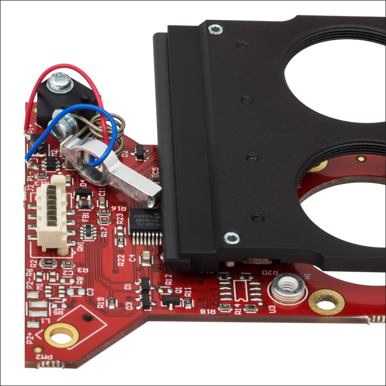
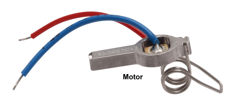
Click to Enlarge
モータには赤と青のワイヤから電力が供給され、アルミニウム製共振器の先端はキャリッジのエッジ部分に接触しています。動作中のモータの先端は、超音波の周波数で微細な周期運動を行います。この動作は人間の目で見ることはできません。

- 製品組み込み(OEM)のための事前評価試験に適した製品
- セットアップに簡単に組み込み可能
- 手動やPC制御で操作
こちらのマルチポジションスライダのセットには、別途単体でも購入が可能なスライダと、下の表に記載されているコンポーネントが含まれています。ELL6にはモータが1つ付いており、USBを介して制御と電力供給を同時に行うことができます。ELL12とELL9にはモータが2つ付いており、より大きな電力が必要になります。そのため、それぞれのセットには5 V電源が付属します。
こちらのパッケージは、実験のセットアップや様々なアプリケーションに素早く組み込むことができます。また、この技術を製品に組み込むかどうかを評価するためにご利用いただくのも便利です。
| Kit Components | |||
|---|---|---|---|
| Item # | Slider | Accessories | Power Supply |
| ELL12K | ELL12 Slider with Six SM05-Threaded Ports | Interface Board, USB Cable, Ribbon Cable (8-Conductor, 28 AWG) | 5 V Power Supply with Region-Specific Plug |
| ELL6K | ELL6 Slider with Two SM1-Threaded Ports | - | |
| ELL9K | ELL9 Slider with Four SM1-Threaded Ports | 5 V Power Supply with Region-Specific Plug | |

 ズーム
ズーム| Item # | # of Ports | Port Thread |
|---|---|---|
| ELL12 | 6 | SM05 (0.535"-40) |
| ELL6 | 2 | SM1 (1.035"-40) |
| ELL9 | 4 |
- マルチポジションスライダの単体製品、SM05またはSM1の内ネジ付きポート
- 既存のインターフェイスボードを介した操作、またはTTL RS-232マルチドロップインターフェイス経由での直接操作
- インターフェイスボードやケーブルを必要としない用途に対応
- 既存のElliptec®デバイスネットワークの拡大に使用可能
こちらのマルチポジションスライダは単体の製品です。こちらはネットワーク化された複数のElilptec®共振モータを必要とする場合や、上記のセットに含まれる他のコンポーネントが必要ではない場合などに、よくご利用いただいている製品です。キャリッジの各位置にはSM05またはSM1の内ネジ(深さ3.5 mm)が付いています。PCBには当社の30 mmケージシステムに対応する4つのタップ穴があり、これによりケージシステムへの取り付けが可能です。
スライダのPCBにはオス型の8ピンPicoflex®コネクタ(ヘッダ)が付いています。すべての単体製品には、基板上のコネクタ(ヘッダ)に接続するためのメス型8ピンPicoflex®コネクタ(レセプタクル)が付属します。詳細は、「ピン配列」タブをご覧ください。

 ズーム
ズーム| Specifications | ||
|---|---|---|
| Item # | ELLC2 | |
| DC Voltage Input to Controller | 4.5 to 5.5 V | |
| Typical Current Consumption Per Module | Movement | 800 mA |
| Standby | 50 mA | |
| Operating Temperature Range | 15 to 40 °C | |
| Ribbon Cable Length (1 Included) | 250 mm (9.84") | |
| Maximum Supported Ribbon Cable Length | 500 mm (19.68") | |
| Dimensions (Interface Only) | 66.0 mm x 32.0 mm x 12.5 mm (2.60" x 1.26" x 0.49") | |
| Weight (Interface Only) | 10.8 g (0.022 lbs) | |
- 単品のELLシリーズ製品に追加して1組のキットを構成するための下記のコンポーネントのセット
- ハンドヘルドコントローラ
- USB Micro Bケーブル
- Picoflex®1ケーブル
- 5 V電源、国内対応アダプタ
アップグレード用アクセサリーキットELLC2は、単品のELLシリーズのスライダ、ステージ、マウントをお持ちの場合に、それに追加して上記のようなELLセット一式2とするためのコンポーネントを揃えたキットです。接続されたELLステージの位置は、付属のハンドヘルドコントローラの3つのボタンで制御することができます。またUSBポートと付属のUSB Micro Bケーブルを介して、PCと直接接続することができます。キットには、ハンドヘルドコントローラとELLデバイスを接続するための0.25 mのPicoflex®ケーブル(8負荷回路)と、5 V電源(国内対応アダプタ付き)も含まれています。
- 注: Picoflex®はMolex社の登録商標です。
- ELL17/M、ELL18/MおよびELL20/M用の取付けブラケットのご注文は当社までご連絡ください。

 ズーム
ズーム| Specifications | ||
|---|---|---|
| Item # | ELLB | |
| Voltage Rating | 4.5 to 5.5 V | |
| Typical Current Consumption Per Module | Movement | 800 mA |
| Standby | 50 mA | |
| Maximum Board Current | 4.0 A | |
| Operating Temperature Range | 15 to 40 °C | |
| Ribbon Cable Length (4 Included) | 250 mm | |
| Maximum Supported Ribbon Cable Length | 500 mm | |
| Dimensions | 65.0 mm x 32.0 mm x 12.5 mm (2.56" x 1.26" x 0.49") | |
| Weight | 11 g (0.02 lbs) | |
Click to Enlarge
1個のバス分配器で最大4個のElliptecデバイスを制御できます。バスは上記のセットに付属しているインターフェイスボードでPCに接続可能です。このときバスはElliptecソフトウェアによって制御され、インターフェイスボード上のボタンは無効になっていますのでご注意ください。
- 1つのバスで最大4台までのElliptec®デバイスに対する制御と電源供給が可能
- 分配器をデイジーチェーン接続すると最大16台までのElliptecデバイスを制御可能
- Elliptecシステムソフトウェア(上記の「ソフトウェア」タブ参照)によるリモート制御
- Elliptec製品のセットに付属するUSBインターフェイスボードを使用してPCに接続可能
- ジャンパ5個およびリボンケーブル(8芯、AWG28)4本が付属
- Raspberry Pi®とArduino®ボードにも対応
バス分配器ELLBには、最大4台までのElliptec®デバイスを接続できます。 接続されたデバイスは上記のセットに付属するインターフェイスボードで制御可能ですが、それが無くても制御できます。インターフェイスボードを使用する場合は、接続された各デバイスはElliptecソフトウェアパッケージが動作するPCによってリモート制御されます。インターフェイスボードは、分配器のREMOTEと記載されているバス信号の入力ポートに接続します。この接続を行うと、インターフェイスボードのボタンは無効になります。インターフェイスボードを使用せずにカスタム接続する場合は、「ピン配列」タブをご覧ください。
複数のバス分配器ELLBをデイジーチェーン接続すると、最大16台までのElliptecデバイスに対する制御と電源供給が可能になります。単純に4つの出力ポート(MODULE)の内の1つを、次のボードの入力ポート(REMOTE)に接続するだけで動作します。LEDインジケータによりどのデバイスが動作しているかが示されます。ソフトウェアで各デバイスを個別にアドレス指定する方法については、通信プロトコルマニュアルをご参照ください。ソフトウェアと付属文書のダウンロードリンクは「ソフトウェア」タブにございます。
バス分配器には、最大電流4 Aの5 V電源を接続するためのØ6.3 mm電源コネクタが付いています。より多くのデバイスを接続して各ユニットを同時に制御するには、電源からより多くの電流を供給する必要があります。 各Elliptecデバイスによって消費される電流については、「仕様」タブをご覧ください。5V、2 Aの電源が上記ELL9およびELL12に付属しています。接続されたElliptecデバイスの消費電流に応じて、電源は同時に2つのデバイスに対して電流の供給ができます。
機能を追加するための制御ピンが14個付いています(右の写真参照)。ピンの4組のペアがそれぞれジャンパで短絡されているとき、つまりジャンパがセットされているときは、Elliptecソフトウェアは接続されたElliptecデバイスからのフィードバック信号を受信することができます。 LEDと記載されているピンのペアはジャンパで短絡されていますが、これを取り外すとLEDインジケータは無効になります。 5VとGNDと記載されたピンを用いると、Ø6.3 mm電源コネクタに接続された電源の代わりに、お手持ちの5 V、2 A 電源を使用することができます。 RX とTX と記載されたピンを用いると、Elliptecインターフェイスボードの代わりに、Raspberry Pi®やArduino®ボードでバスを制御することができます。
ボードは四隅にあるØ3.5 mm貫通穴を使用して取り付けます。リボンケーブル(8芯、AWG28)は4本付属します。
| Compatible Elliptec Devices | |||||
|---|---|---|---|---|---|
| | | | | |
| Multi-Position Sliders | 28 mm Linear Stage | 60 mm Linear Stage | Rotation Stage | Rotation Mount | Motorized Iris |

 ズーム
ズーム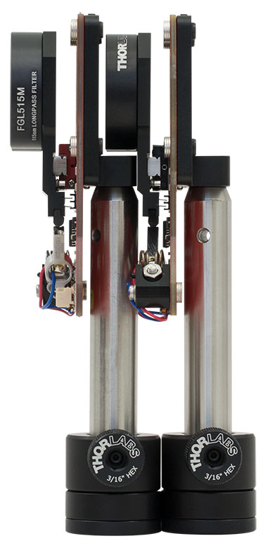
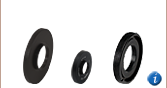
Click to Enlarge
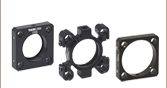
ELLA1は4つの#4-40ネジ穴を使用してスライダのPCBの裏面に取り付けられます。ネジ穴間隔は30 mmケージシステムに適合しています。
- マルチポジションスライダのPCBに直接取り付け可能
- 表面の貫通スロットがPCB裏の突出部に対応
- #4-40ネジを使用するザグリ穴が4つ
- M4ネジを使用するザグリ穴が1つ
- SM1内ネジ
ポスト取付け用アダプタELLA1は付属の#4-40ネジ4つを使用してマルチポジションスライダのPCBの裏面にしっかり固定されます。その後アダプタの底部にあるザグリ穴とM4ネジ(付属していません)を使用してスライダをØ12 mm~Ø12.7 mm(Ø1/2インチ)ポスト等に取り付けることができます。SM1内ネジ付き内孔は、レンズチューブなどの部品をアダプタに結合することが可能です。4つのザグリ穴はØ6 mmケージロッドを使用してELLA1を30 mmケージシステムに接続することもできます。
全体の寸法が40.0 mm x 44.0 mm x 14.0 mmで、スライダのPCB裏面に密接してポストを取り付けられることから、特にスライダを前後に配置する必要のある用途でのご使用にお勧めいたします。このように前後に並べる設置では、スライダに取り付けられた光学素子が1つ前のポストの真上に配置されるようになります。こちらのアダプタは一般的な用途で1つの部品を取り付ける際にもご使用いただけます。