 Products Home
共振ピエゾモーター付き回転マウント
- SM1-Threaded Rotation Mount with Closed-Loop Positioning
- Open Frame Design for OEM Applications
- Control via Interface Board, GUI, or ASCII Message Calls
- Fully Integrated Drive Electronics
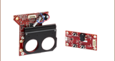
ELL14K
Rotation Mount
Bundle
(Mount and Board Included)
Rotation Mount for Ø1" or Ø25.0 mm Optics
(Also Available Individually)
Interface Board
Application Idea
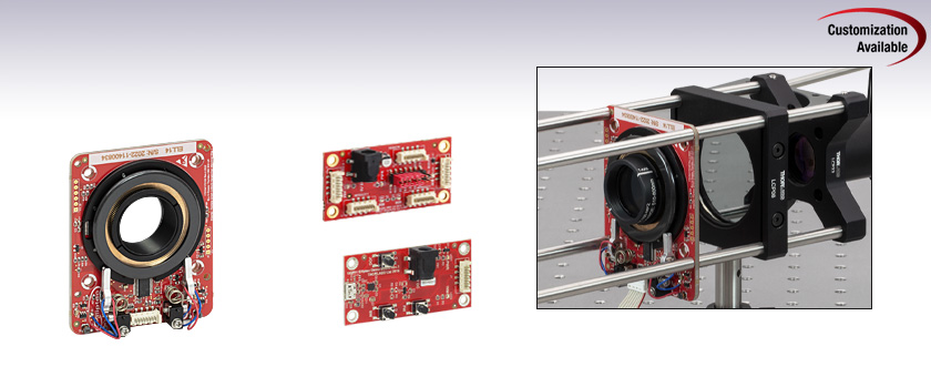
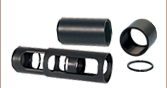
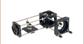
The ELL14K rotates a mounted, SM1-threaded polarizer within a 60 mm cage assembly.
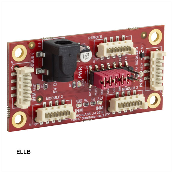
ELLB
Bus Distributor


Please Wait
| Key Specificationsa | ||
|---|---|---|
| Travel (No Limit Switches)b | 360° Continuous | |
| Homing Repeatability | 1.75 mrad (0.1°) | |
| Bidirectional Repeatability | 873 µrad (0.05°) | |
| Velocity (Maximum) | 430 °/s | |
| Maximum Total Load | 50 g (1.76 oz)c | |
| DC Voltage Input | 4.5 to 5.5 V | |
| Weight of Mount | 80 g (2.82 oz) | |
| Minimum Lifetimeb | 100 km (> 600 000 Revolutions) | |
| Mount Dimensions | 66.0 mm x 82.5 mm x 19.0 mm (2.6" x 3.25" x 0.75") | |

Click to Enlarge
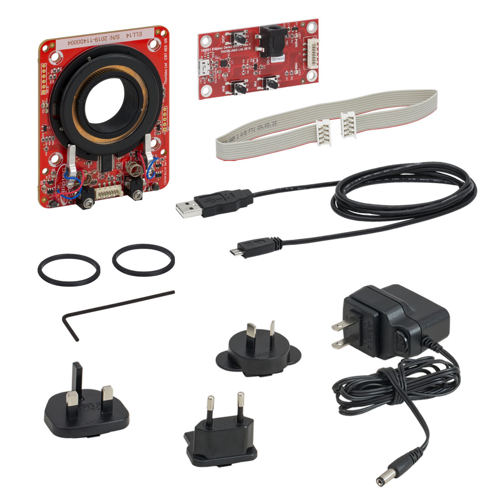
各コンポーネントを接続した回転マウントセットELL14K。主要部の名称も記載しています。

特長
- 製品組み込み(OEM)用途のほか、迅速で精密な回転を必要とする用途に適した製品
- 制御信号用にMicro-B USBおよびPicoflex®1コネクタ
- マルチドロップ接続用のシリアル通信プロトコルをサポート
- Ø25 mm~Ø25.4 mm(Ø1インチ)光学素子用SM1ネジ付き回転マウント
- 赤外線および磁気センサ技術によりホームポジションの絶対位置を検出
- 磁気式エンコーダを用いた位置決めマウント
- バス分配器で最大4台までのElliptec®デバイスの制御が可能
- アップグレード用アクセサリーキットELLC2をご用意(下記参照)
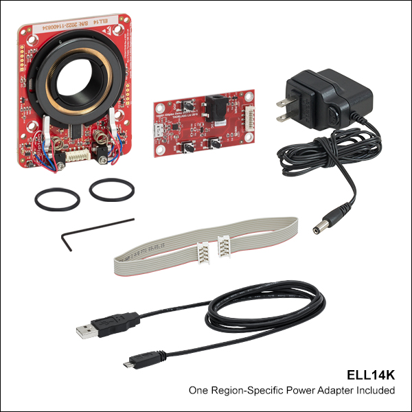
当社のElliptec®共振ピエゾモータ技術を用いたこちらの回転マウントは、光学素子を回転させる必要がある用途に適したコンパクトな製品です。回転ステージは単品(ELL14/M)またはセット(ELL14K/M)の一部としてご提供しております。セットには、マウントを手動制御するためのインターフェイスボード、取付け用ブラケット、電源、マウントとインターフェイスボードを接続するためのケーブル、およびインターフェイスボードとPCを接続するためのケーブルも含まれます。当社では、単品のステージをセットにアップグレードするためのアクセサリーキットELLC2もご用意しております。
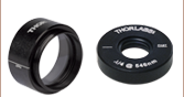
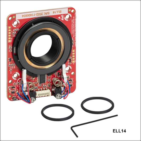
マウントの回転セルにはSM1内ネジが付いており、Ø25 mm~Ø25.4 mm(Ø1インチ)光学素子を取り付ける固定リングSM1RRが2つ付属しています。回転マウントは軽量かつコンパクトで、閉ループ動作を行うことにより、設定した位置に対する回転の再現性として873 µradが得られます。右の写真はELL14Kの各コンポーネントを接続した状態を示しており、主要な部分の名称も記載されています。モータの詳細については「Elliptec®モータ」タブをご覧ください。
モータは極めて動的特性に優れ、ギアもありません。2つのモータの先端は、右の写真のように、マウント底部のプラスチック製トラックにしっかりと接触しています。モータは互いに反対の回転方向に向けて取り付けられています。どちらの向きに回転する場合でも、一方のモータがトラックを押し、もう一方のモータが反対方向に引っ張るときに回転します。回転マウントは連続動作用としては設計されておりません。また、デューティ比40%以下での動作をお勧めいたします。モータに電力が供給されていないときは、停止したモータの2つのアームにより、合わせて約0.01 N·mのトルクでマウントの位置が保持されます。
この回転マウントはオープンフレームであるうえ汎用性と単純性を備えているため、お客様の要件に合ったカスタマイズと大量生産が可能であり、従って製品組み込み(OEM)用途に適しています。お客様の要件を当社までお知らせいただければ、お客さまの用途やニーズに合ったソリューションをご提案いたします。
制御
こちらの回転マウントへの電力供給や、駆動および制御方法には様々な選択肢がございます。詳細については「取扱い」タブ内の「回転マウントの位置決め」をご覧ください。マウントには3.3 Vシリアルバスが備わっており、インターフェイスボードの有無にかかわらず操作可能な設計になっています。ピンの割り当てについては「ピン配列」タブをご覧ください。当社では、マウントを完全に独立して制御できるElliptec製品用ソフトウェアをご提供しております。インターフェイスボードをアクセサリとして用いてマウントの位置を変更した場合、ソフトウェア内でのマウントのステータス情報は自動的に更新されます。
| Elliptec Resonant Motor Products | |||||
|---|---|---|---|---|---|
 |  |  |  |  |  |
| Multi-Position Sliders | 28 mm Linear Stage | 60 mm Linear Stage | Rotation Stage | Rotation Mount | Motorized Iris |
複数のElliptecデバイスは、バス分配器ELLBを使用するか、1本のリボンケーブルに複数のコネクタを接続することで制御が可能です。1個のバス分配器で最大4台までのElliptecデバイスを接続できます。さらに分配器をデイジーチェーン接続することで、最大16台までのデバイスを接続することができます。このバスは、Elliptecソフトウェアが動作しているPCとのインターフェイスボード(下記のセットに付属)を介した接続、Arduino®2またはRaspberry Pi®3ボードとの接続、お手持ちの制御ボードとのコネクターピンを介した接続の3つの方法のうちのいずれかを用いることで制御できます。または、1本のリボンケーブルに最大16台のデバイスを接続することもできます。各デバイスはインターフェイスボードで同時に制御することも、Elliptecソフトウェアでデバイスを選択して制御することもできます。複数のデバイスをリボンケーブルに接続する方法については マニュアルを、カスタム接続するときのピン配列については「ピン配列 」タブをご覧ください。
- PicoflexはMolex社の登録商標です。
- ArduinoはArduino社の登録商標です。
- Raspberry PiはRaspberry Pi財団の登録商標です。
| Specificationsa | |
|---|---|
| Performance | |
| Travel | 360° Continuousb |
| Maximum Speedc | 430 °/s |
| Bidirectional Repeatabilityd | 873 µrad (0.05°) |
| Homing Repeatability | 1.75 mrad (0.1°) |
| Bidirectional Accuracye | 6.98 mrad (0.4°) |
| Backlash | 226.9 µrad (0.013°) |
| Encoder Resolution (Relative Magnetic Encoder) | 143360 counts/rev (43.8 µrad/count) (0.0025°/count) |
| Minimum Incremental Motion | 34.9 µrad (0.002°) |
| Minimum Holding Torque (Both Motors Engaged) | 0.01 N•m |
| Axis Wobblef | 244.3 µrad (0.014°) |
| Maximum Total Loadg | 50 g (0.11 lb) |
| Minimum Lifetimeh | > 600 000 Revolutions (100 km) |
| Electrical | |
| Motor Type | Elliptec® Resonant Piezo |
| DC Voltage Input | 4.5 to 5.5 V |
| Typical Current Consumption, During Movement | 800 mA |
| Typical Current Consumption, During Standby | 50 mA |
| Communications | |
| Bus | Multi-Drop 3.3 V/5 V TTL RS232 |
| Connector on Rotation Stage Board | Picoflex® |
| Connectors on Interface Board | Picoflex®, Micro USB, DC Jack [6.3mm OD (GND), 2.1mm ID (+5V)] |
| Speed | 9600 baud |
| Data Length (1 Stop Bit, No Parity) | 8 bit |
| Protocol Data Format | ASCII HEX |
| Module Address and Command Format | Mnemonic Character |
| Mechanical | |
| Mounting Thread | SM1 |
| Dimensions of the Rotation Mount Board | 66.0 mm x 82.5 mm x 19.1mm (2.6" x 3.25" x 0.75") |
| Weight of Rotation Mount Board | 80 g (0.176 lb) |
| Environmental Operating Conditions | |
| Temperature Range | 15 to 40 °C (59 to 104 °F) |
| Maximum Relative Humidity (Non-Condensing) | < 80% at 31 °C |
| Maximum Altitude | 2000 m |
Click to Enlarge
インターフェイスボードの図面
| Connector J1 Pinouta | ||
|---|---|---|
| Pin | Type | Function |
| 1 | PWR | Ground |
| 2 | OUT | OTDX - Open Drain Transmit 3.3 V TTL RS232 |
| 3 | IN | RX Receive - 3.3 V TTL RS232 |
| 4 | OUT | In Motion, Open Drain Active Low Max 5 mA |
| 5 | IN | JOG/Mode, Active Low Max 5 V |
| 6 | IN | BW Backward, Active Low Max 5 V |
| 7 | IN | FW Forward, Active Low Max 5 V |
| 8 | PWR | VCC +5 V ±10%; 800 mA |
| ELLB Connector J1, J2, J3, and J4 Pinouta,b | ||
|---|---|---|
| Pin | Type | Function |
| 1 | PWR | Ground |
| 2 | OUT | OTDX - Open Drain Transmit 3.3 V TTL RS232 |
| 3 | IN | RX Receive 3.3 V TTL RS232 |
| 4 | OUT | In Motion, Open Drain Active Low Max 5 mA |
| 5 | IN | Not Connected |
| 6 | IN | Not Connected |
| 7 | IN | Not Connected |
| 8 | PWR | VCC +5 V ± 10%; 800 mA per Connected Device |

Click to Enlarge
バス分配器ELLB上のPicoflex®コネクタのピン配列図。
左上はELLBの簡略図です。コネクタ上の極性を示すマークが、
8ピンコネクタ付きケーブルの赤いワイヤに近くなるように
接続してください。
使用上の注意事項
こちらのタブでは、回転マウントセットELL14Kの取扱いや、取付け、操作方法に関する情報がご覧いただけます。
目次
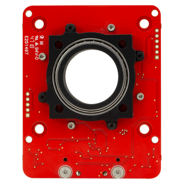
Click to Enlarge
回転マウントの背面
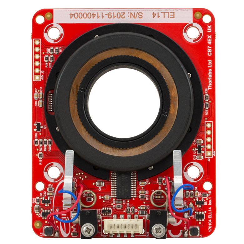
Click to Enlarge
回転マウントの正面
取扱い
ELL14Kの回転マウントおよびインターフェイスボードは、一般的な取扱いに対しては堅牢に作られています。動作の信頼性を確保するために、モータが接触するプラスチック製のトラックには油、汚れ、埃が付かないようにしてください。回転マウントを取り扱う際に手袋の着用までは必要ありませんが、トラックに油脂を付着させないために、手指で触れないようにご注意ください。トラックが汚れた場合には、イソプロピルアルコールまたはミネラルスピリット(ホワイトスピリット)で汚れを拭き取ってください。アセトンはプラスチック製のトラックを損傷しますので使用しないでください。
ELL14はオープンフレームですが、8 kVまでの静電気放電(ESD)には耐えられます。しかしESDに対する対策は講じてください。放電によって生じる電気信号によって、マウントが意図しない動きをする可能性があります。500 gを超える曲げ荷重をボードに加えるとPCBが変形し、回転マウントの性能が劣化します。マウントのホーミングおよび位置決めには、磁気センサから読み取った情報が使用されるため、PCBの構造に過大な荷重を加えたり、磁界を印加したりしないでください。ホーミングおよび位置決めに悪影響を及ぼさないために、磁気センサ付近の磁界の強さは±5 mT以下に制限してください。
回転マウントの取付けと負荷
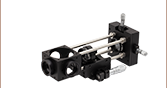
回転マウントは垂直方向または水平方向のどちらにも取り付け可能です。水平方向に取り付ける場合は、Elliptecモータは上向きになるように取り付けてください。このマウントには様々な取り付け機能があり、当社のコンポーネントと組み合わせて使用したり、あるいはカスタム仕様のOEMアセンブリ内で使用したりすることができます。60 mm間隔であいている4つのØ3.0 mm貫通穴を用いれば、当社の60 mmケージシステムに取り付けられます。またこれらの貫通穴にM3ネジを通して固定すれば、カスタム仕様の構造物に取り付けることも可能です。さらに50 mm間隔であいている4つのØ4.2 mm貫通穴を用いて、M5ネジでカスタム仕様のマウントに取り付ることもできます。マウントの背面には30 mm間隔でM3固定ネジ(セットスクリュ)の付いたØ4.0 mmの穴が4つあり、これには当社のSRシリーズケージロッドを取り付けることができます。各マウントには、これらのネジを固定するための1.5 mm六角レンチが付属しています。SRシリーズケージロッドは、当社のアダプタELLA1 を取り付けてポストに取り付けたり、ERシリーズケージロッドを取り付けて30 mmケージシステムに組み込んだりするのにもご利用いただけます。下の写真では3種類の取付方法を示しています。
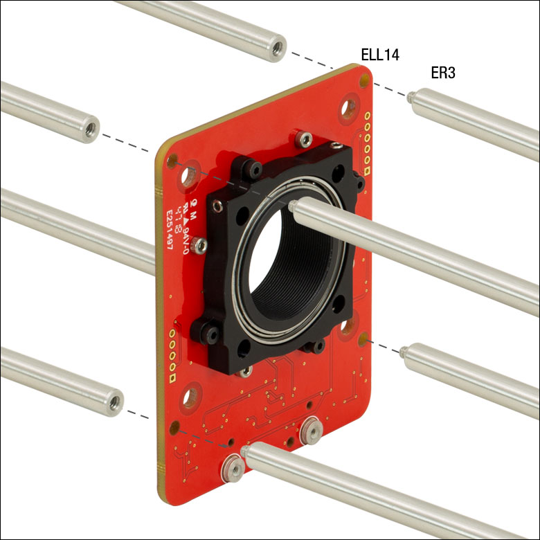
Click for Details
回転マウントは四隅のØ3.0 mm取付け穴を用いてPCBを両側から2本のケージロッドで挟むことで60 mmケージシステムに取付け可能です。
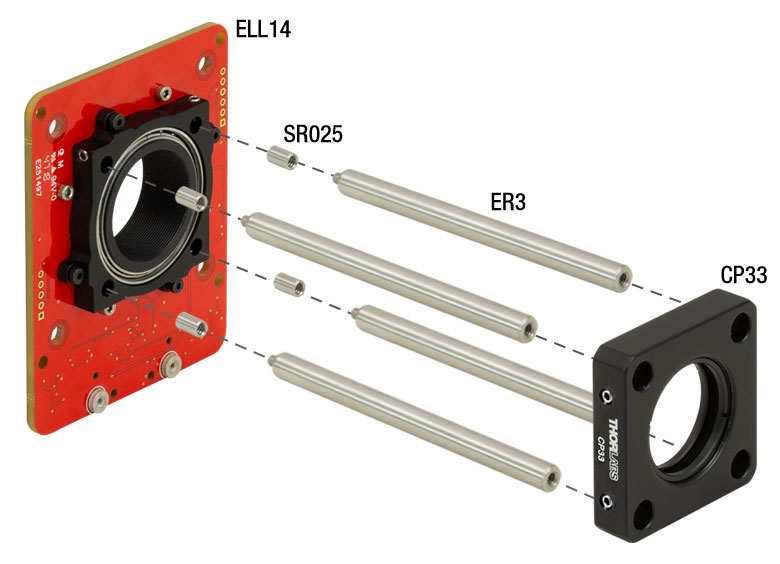
Click for Details
回転マウントはマウント背面のØ4.0 mm穴とケージロッドSR025を用いて30 mmケージシステムに取付け可能です。
Click to Enlarge
回転マウントの概要図
搭載可能な最大許容荷重は50 gです。50 gまで搭載するには、荷重がマウントの中心にかかるようにしなければなりません。回転マウントの取り付けや負荷の取り付けに際しては、回転マウントの可動部分と干渉するものが無いこと、また動作時にマウントと負荷が揺れないようにしっかり固定されていることを確認してください。マウントや負荷が揺れるとエンコーダーエラーが発生する場合があります。
電力の供給
インターフェイスボードを使用している時は、電力はそのボード上のMicro-B USBコネクタまたは5 VDC電源ソケットから供給可能です。インターフェイスボード上の電子回路により、入力されたDC信号は必要とされる共振周波数の正弦波信号に変換されます。
ELL14Kのセットには 5 VDC電源が付属し、そのコネクタはインターフェイスボードの電源ソケットに接続できます。このソケットを介して電力を供給する場合は、Micro-B USBコネクタをUSBケーブルでPCに接続するために使用できるので、マウントをリモート制御することができます。USB 2.0接続でPCから供給される電力は、マウントを駆動するのに十分ではありません(当該事項の詳細はマニュアルを参照)。PC制御を必要としない場合は、携帯型のUSB 5 Vバッテリーパックをインターフェイスボード上のMicro-B USBコネクタに接続して、マウントに電力を供給することもできます。
インターフェイスボードを使用しない場合には、回転マウントのボードに付属するPicoflexコネクタ上のピンを介して電力を供給することができます。 このコネクタのピン配列は「ピン配列」タブに記載されています。回転マウントへの電力供給やアドレス指定に関する詳細は、それぞれマニュアルや通信プロトコルマニュアルをご参照ください。
モータの動作
回転マウントの動作は、ピエゾ素子を特定の超音波周波数で振動させることにより制御します。個々のマウントには、マウントを前方に押し出す固有の共振周波数とマウントを反対方向に引っ張る別の共振周波数があります。モータを一方の共振周波数で駆動すると、モータの先端は小さな楕円形の軌跡を時計回りに連続的に描きます。モータをもう一方の共振周波数で駆動すると、先端は同じ軌跡を反時計回りに描きます。どちらの共振周波数も100 kHz近辺です。モータ先端の総変位量は、駆動する機械的負荷とピエゾ素子に供給される電圧に依存します。負荷を付けずに最大電圧5 Vの共振周波数で駆動すると、モータの先端は数μm以下の伸縮動作を行って楕円を描きます。 詳細については「Elliptec™モータ」タブと、モータの動作原理について説明している動画をご覧ください。
回転マウントのホーミング
Click to Enlarge
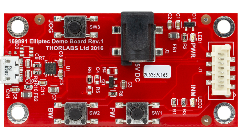
インターフェイスボード

Click to Enlarge
インターフェイスボードの概要図
マウントのホーミングは、インターフェイスボード上のBWボタンの押下、Elliptecソフトウェアのグラフィカルユーザーインターフェイス(GUI)内のHomeボタンのクリック、または通信プロトコルマニュアルに記載されている適切なASCIIメッセージの送信によって実行されます。
デフォルトのホーム位置は、マウントアセンブリ上にあらかじめ設定されています。ホーム位置は、必要に応じて、デフォルトの位置から+90°(時計回りに1/4回転)までの範囲でオフセットして再設定することができます。このようなホーム位置のカスタマイズは、複数のマウントの向きを同期して動かす際に便利です。ホームコマンドを実行すると、マウントはまずおおよそのホーム位置を検出し、その後の精密位置決めのプロセスによって288.0 µradの精度でホーム位置にセットされます。ホーミングの最初のプロセスにおけるマウントの回転方向は、時計回りと反時計回り(マウントを上から見た状態での定義)のどちらかを指定できますが、精密位置決めは再現性を高めるため常に反時計回りで実行されます。
回転マウントの位置決め
この回転マウントは連続動作用としては設計されておりませんのでご注意ください。 一般的な用途においてはデューティ比40%以下で動作させることをお勧めいたします。また、デューティ比60%以上での動作は数秒以下に制限してください。
マウントの位置決めを行う前に、マウントのホーム位置を検出しなければなりません。詳細については前のセクションをご参照ください。マウントの動作はElliptec™ ソフトウェアパッケージ(ダウンロード可能)を介したPC制御、またはマウントボードのデジタル信号線に単純な信号を送信することで制御できます。ソフトウェアと付属文書のダウンロードリンクは「ソフトウェア」タブにございます。
複数のElliptecデバイスは、バス分配器ELLBを使用するか、複数のコネクタを1本のリボンケーブルに接続することで制御できます。1個のバス分配器で最大4台までのElliptecデバイスを接続できます。さらに分配器をデイジーチェーン接続することで、最大16台までのデバイスを接続することができます。このバスは、Elliptecソフトウェアが動作しているPCとのインターフェイスボード(下記のセットに付属)を介した接続、Arduino®またはRaspberry Pi®ボードとの接続、お手持ちの制御ボードとのコネクターピンを介した接続の3つの方法のうちのいずれかを用いることで制御できます。なお、インターフェイスボードをご使用の場合、ボード上のボタンは無効になります。または、1本のリボンケーブルに最大16台のデバイスを接続することもできます。各デバイスはインターフェイスボードで同時に制御することも、Elliptecソフトウェアでデバイスを選択して制御することもできます。複数のデバイスをリボンケーブルに接続する方法についてはマニュアルを、カスタム接続するときのピン配列については「ピン配列 」タブをご覧ください。ソフトウェアで各デバイスを個別にアドレス指定する方法については、通信プロトコルマニュアルをご参照ください。ソフトウェアと付属文書は「ソフトウェア」タブからダウンロードいただけます。
マウントが前方あるいは後方へ移動するステップサイズのデフォルト値は45°ですが、Elliptecソフトウェアを使用するか通信プロトコルマニュアルで規定されている適切なASCIIメッセージを送信することによりカスタマイズすることができます。マウントは前後にジョグ動作をするほかに、Elliptecソフトウェアを用いて絶対位置あるいは相対位置へ移動することも可能です。また前述のとおり、ソフトウェアを用いれば、ジョグ動作のステップサイズの設定、マウント位置の読み取り、さらにホーム位置の調整を行うことも可能です。
23.8 µradの角度分解能を有する磁気センサから読み取った情報は、マウントの位置決めやホームコマンドを実行する際に使用されます。マウントの移動範囲に制限はありませんが、マウントの回転位置は常に0°~359.99°の値で表示されます。マウントの最小移動量は34.9 µradで、磁気センサからの信号を用いた位置決めの再現性は873 µradです。
マウントは、位置誤差補正アルゴリズムを用いて、正確な位置決めを効率的に習得します。マウントが新しい位置へ移動すると、要求された位置と実際の位置との誤差を検出します。これによりマウントの位置が修正され、誤差の補正値が算出されます。このアルゴリズムでは誤差の補正値が順次更新され、マウントが次の位置に移動する際に適用されます。一般に2~6回移動すれば最適な誤差補正値が得られます。
共振周波数
工場出荷時の初期設定では、回転マウントの駆動用モータの電源投入時に、最良の性能が得られる共振周波数の検出作業を行うように設定されています。そのプロセスで回転マウントは前後にわずかに移動します。起動時のこの動作が望ましくない場合には、シリアルポートを使用して電源投入時の周波数を初期化することで、この校正プロセスを無効にすることができます。最適な共振周波数の検出はいつでも実施可能ですが、適切な性能を維持するために、荷重や周囲温度の変化したときには、新たにこの検出作業を実施することをお勧めします。詳細についてはマニュアルをご参照ください。
Click to Enlarge
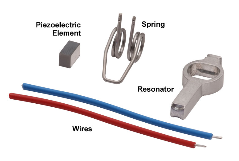
Elliptecモータの部品
Click to Enlarge
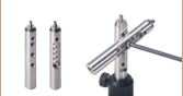
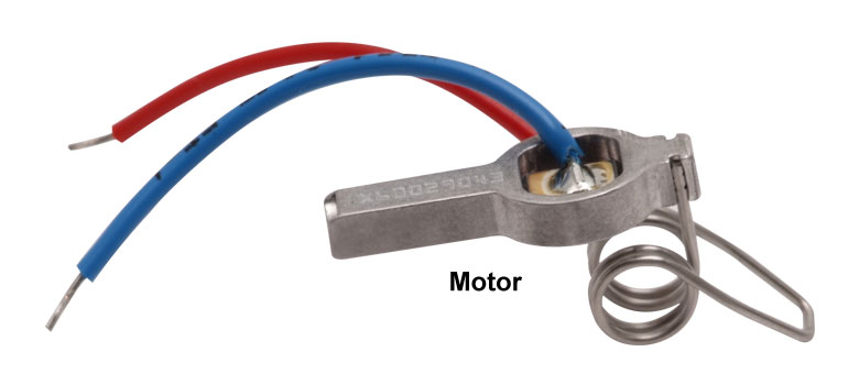
Elliptec共振ピエゾモータ
Elliptec®共振ピエゾモータ
右に示した当社のElliptec®共振ピエゾモータの質量は1.2 gと軽量で、共振器筐体の寸法はバネを除いて8 mm×4 mm×20 mmとコンパクトです。
モータの部品
モータを構成する部品は右端の写真でご覧いただけます。ピエゾ素子はアルミニウム製の共振器内に圧入されています。共振器はその先端が必要とされる楕円形の動作をし、駆動されるモジュールと適切に接触するよう精密設計・精密加工がなされています。バネの自由端側は共振器筐体に組み込まれています。ピエゾ素子の上部ならびに底部にはんだ付けされているワイヤには、ピエゾ素子を超音波周波数で振動させるための電圧信号を供給します。
モータをシステム内に組み込むときは、バネの開ループ側を駆動される対象物に対して動かない頑丈な面に固定し、共振器の先端は対象物に接触させます。バネの目的は共振器の先端と駆動対象物との接触を一定に維持することです。また移動方向はピエゾ素子を駆動する2つの共振周波数によって決まります。
楕円形の動作と一般的なモータとの比較
このモータは、2つの共振周波数のうちのいずれかで駆動することにより動作します。超音波周波数で振動する電圧信号がピエゾ素子に印加されると、ピエゾ素子はその電圧信号の周波数に合わせて1 µm以下のレベルで伸長し、また元の寸法にまで収縮します。ピエゾ素子の寸法がこのように高速のサイクルで変化すると、アルミニウム製の共振器に振動が発生します。この振動が筐体の共振周波数のうちの一方の周波数で生じているときに、モータの先端に押す動作が発生します。もう一方の共振周波数で振動するときは、引っ張る動作が発生します。
動画に示されているように、モータが共振状態で動作している時にはその先端が楕円形の軌跡を描き、それによってこの引っ張る動作と押す動作が発生します。また、楕円の回る方向は選択された共振周波数によって決まります。モータの先端は楕円の半分を描くときは伸び、残りの半分を描くときは縮みます。モータが対象物を押すときは、先端が伸びるときに先端と対象物が接触し、縮むときには接触しません。モータが対象物を引っ張るときは、逆の動作をします。モータ先端の総変位量は、駆動する機械的負荷とピエゾ素子に供給される電圧の両方に依存します。駆動電圧のピーク値が5 Vのとき、最大変位量は数µmまで大きくなる可能性があります。
このモータはDCモータあるいは電磁ステッピングモータと同じように動作しますが、従来のモータの様々な欠点がありません。従来の電磁モータを停止させるには慣性に伴う遅延を克服する必要がありますが、非常に動的特性に優れたElliptecモータでは数マイクロ秒で停止できます。ギアがないため、バックラッシュも発生しません。磁石も無いため、電磁障害に敏感な用途にも使用できます。駆動される対象物の動きは連続的でスムーズです。駆動対象物を動かすにはモータの先端をそれと接触させる必要があるため、モータには摩擦ブレーキという安全機能が備わっています。プラスチック面に接している場合は、モータは静かに動作します。
製品組み込み(OEM)用途のためには、低コストに抑えるためモータを大量生産し、低価格のアナログ電子回路で駆動することもできます。マイクロプロセッサやソフトウェアは必要ありませんが、対応は可能です。
Click to Enlarge
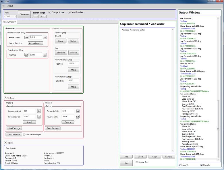
Elliptec共振ピエゾモーター用コントロールソフトウェアのGUI
Elliptec®共振ピエゾモータで駆動されるデバイス用のソフトウェア
Elliptec®共振ピエゾモータをベースとする全てのデバイスは、直感的なGUIを用いたElliptecシステムソフトウェアで制御することができます。ダウンロード可能なソフトウェア一式にはC#フォーマットのソースコードが含まれており、カスタム仕様のアプリケーションをあらゆる言語で作成することができます。右はGUIのスクリーンショットです。また下のボタンをクリックするとダウンロードのページがご覧いただけます。
コマンドはGUI画面の中央右寄りにあるSequencer command / wait orderに入力します。デバイスに送信するコマンドとして、例えば「Aho0」はアドレス「A」の回転ステージを時計回りにホーム位置に動かすコマンドで、「Afw」はアドレス「A」のマウントをジョグ動作で前方に動かすコマンドです。 コマンド「As1」は、アドレス「A」のモータ1に対して、 現在の動作条件に適した共振周波数の検出作業を実施させます。
ソフトウェア
バージョン1.6.3
操作しやすいGUIを備えたElliptecシステムソフトウェアが含まれています。通信プロトコルマニュアルもダウンロードできますが、これにはElliptecソフトウェアパッケージの通信コマンドの詳細が記載されています。
| Posted Comments: | |
user
(posted 2024-03-16 18:08:35.72) Is it possible to control the motor via Labview? Could you share a basic version of the software? Thanks cstroud
(posted 2024-03-18 12:20:26.0) Thanks for reaching out. The Elliptec stages are controllable via Labview when using the DLL's, which are downloaded when installing the ELLO software. I will contact you directly to send over some examples. Lin Lin
(posted 2024-03-06 11:07:58.547) After one rotation round, I found that the mount could not return to its original (absolute) angle when I clicked home or stepped back to its original position.
Is there any problem with the hysteretic effect? Or how can I solve the problem? Looking forward to the solution. do'neill
(posted 2024-03-12 08:52:17.0) Thanks for reaching out with this. The accuracy of these stages should be 6.98 mrad (0.4°) and the homing repeatability should be 1.75 mrad (0.1°). I will reach out to you directly to see if it is beyond these limits and help troubleshoot this issue user
(posted 2024-02-16 10:55:05.083) any chance of a half size/12,5mm version ? spolineni
(posted 2024-02-26 06:49:29.0) Thank you for getting in touch with us. We are looking into your inquiry. In the meantime, we will contact you to discuss the details of your specific application. user
(posted 2023-12-23 16:46:40.74) Hello, my rotation mount will rotate by itself when I place it within coils under sweeping magnetic fields. Do you know what could be the cause of this? Thank you. cstroud
(posted 2024-01-03 06:33:34.0) Thank you for your enquiry. The Elliptec stages are generally unable to be used in a magnetic environment as this can affect the positioning and homing sensor. I will reach out to you directly to discuss this issue. Kévin MORVAN
(posted 2023-11-09 07:53:33.32) Hello, Could you send me an example of a Labview vi that drive the ELL14K. It will be very helpful. Tank you. do'neill
(posted 2023-11-13 07:20:41.0) Feedback from Daniel at Thorlabs. I will reach out to you directly to provide this example. Jeremy Chew
(posted 2023-09-29 01:50:59.663) Hi there,
I am looking to use the ELL14 to jog continuously. After using 0sv46, I can't seem to find a way to stop its rotation. Would appreciate if I can get help on this.
Thank you! do'neill
(posted 2023-10-10 06:38:00.0) Response from Daniel at Thorlabs. The serial command 0st (where 0 is your address) will stop the motor when in continuous motion. Details on this can be found on page 37 of the Communication Protocol. user
(posted 2023-09-14 19:32:47.073) Hello. Can I get sample C++ programs for ELL14 and ELLB? Thanks. do'neill
(posted 2023-09-22 06:50:05.0) Response from Daniel at Thorlabs. I will reach out to you directly with this. Rishav Koirala
(posted 2023-09-14 11:47:32.717) Hello, could you please share some LabVIEW examples to interface with this mount and program it? That would be very helpful. Thanks. do'neill
(posted 2023-09-15 07:17:32.0) Response from Daniel at Thorlabs. I will reach out to you directly to discuss this and provide some examples. user
(posted 2023-07-12 12:37:34.31) Hi, I am unable to connect to the ELL14 via the Elliptec software--it is unable to detect the device. When I plugged it in for the first time, the drivers did not get installed either. How can I resolve this? do'neill
(posted 2023-07-20 06:15:28.0) Response from Daniel at Thorlabs. I am sorry to hear this. I will reach out to you directly to help troubleshoot this with you. user
(posted 2023-07-12 19:28:14.883) Hi, is it possible to control the rotation speed of the device? I read that the maximum speed is 430 degrees/s, I'd like to tune the speed with custom values up to the maximum one.
Thank you very much for your kind attention and help do'neill
(posted 2023-07-20 05:28:55.0) Response from Daniel at Thorlabs. Whilst these are not designed to be velocity controlled the SV command in the communication protocol can be used to slow the speed but can not be used to set an exact velocity. I will reach out to you directly to discuss your application user
(posted 2023-06-28 15:32:35.677) Hi,
I'm using several rotation mounts ELL14K, and I'm having issues with the last I ordered recently. When setting a position, it takes longer that it should (compared with the others I have, which work fine), making a different sound; it seems it reaches the position and then the the piezos keep vibrating or moving for a second or so. And sometimes I get the error "Device error: Mechanical Timeout". I already reboot the system and reset to factory settings, and cleaned the black bearing with alcohol, though I always manipulated it with gloves. The device has a couple of days of use, and I detected this since the beginning. Do you have any insight of what it could be and how to fix it?
Many thanks in advance do'neill
(posted 2023-06-29 11:51:54.0) Response from Daniel at Thorlabs. There are a few things this could be, I will reach out to directly to try and help you troubleshoot this with you. user
(posted 2023-06-14 08:15:17.473) Hi, I moved the ELL14K to a new PC with Windows11 but it is not recognized anymore via USB. None of the USB ports seems to work, and no driver is installed, then the software does not detect the device, while other devices are correctly working. Thank you very much in advance for your kind support. user
(posted 2023-06-06 14:35:38.597) Hi, trying to program an ELL14 -- would it be possible to get some sample Python code in controlling this device? Thank you. do'neill
(posted 2023-06-07 05:57:05.0) Feedback from Daniel at Thorlabs. I will reach out to you directly to provide this example. user
(posted 2023-05-15 12:35:45.11) Hi, would it be possible to get some labview VI examples for this mount? Thanks! do'neill
(posted 2023-05-16 12:25:56.0) Response from Daniel at Thorlabs. Thank you for your enquiry. I have reached out to you directly to provide an example VI. Thanmay Menon
(posted 2023-04-10 17:14:47.78) Hi, I was wondering if Thorlabs would be willing to provide some labview VI examples to help control the mount? JReeder
(posted 2023-04-12 03:18:50.0) Thank you for your enquiry. I have reached out to you directly to provide an example LabVIEW VI for this product. Alastair Curnock
(posted 2023-02-28 15:48:31.333) I have been using several of the ELL products for the last couple of years with great success for my requirements.
Do you have any plans to release more products in this range?
I would be extremely interested in a version of the ELL14 designed for an SM2 mount, for use with 50mm/2" diameter components JReeder
(posted 2023-03-01 08:29:42.0) Thanks for your enquiry. We are constantly developing more products for our customers and we currently do plan on releasing more Elliptec devices. I have logged your request in our internal engineering forum. user
(posted 2023-02-20 12:40:07.54) Hello, would it be possible for you to send me Labview sample code to control this please? Thank you in advance. do'neill
(posted 2023-02-20 09:44:36.0) Response from Daniel at Thorlabs: Thank you for your enquiry, we will reach out to you directly to help support this. Joelle Youssef
(posted 2023-02-07 13:32:15.473) Hello, the software for Devices Driven by Elliptec® Piezoelectric Resonant Motors is not downloading.
Thank you do'neill
(posted 2023-02-17 06:48:25.0) Response from Daniel at Thorlabs: I am sorry to hear you are finding this, I will reach out to you directly to help troubleshoot this. user
(posted 2023-01-19 16:46:46.833) Hi! Do you have any MATLAB examples to control this device? if not, could I get some help in setting up to communicate with ELL14 in MATLAB environment?? DJayasuriya
(posted 2023-01-20 09:12:05.0) Thank you for your inquiry. We have got in touch with you directly. user
(posted 2023-01-18 12:04:58.387) Hello, Could you send some Labview examples if you have any? thank you in advance. do'neill
(posted 2023-01-19 09:12:36.0) Response from Daniel at Thorlabs: Thank you for your inquiry. We will get in touch with you directly to support this. Jooyeong Yun
(posted 2023-01-12 02:27:16.93) Hi, Can I get customized ELL14k to support faster rotation above 1800 degree/s and possibly with 2inch aperture? if not, are there other products that can support these specs? (The faster the better) I could not find any and would appreciate your help. Thanks! fguzman
(posted 2023-01-12 09:34:42.0) Thank you for your enquiry. The maximum speed for the ELL14 is 430 deg/sec, and has a 1" aperture. We will contact you directly to discuss your application. fguzman
(posted 2023-01-12 09:34:42.0) Thank you for your enquiry. The maximum speed for the ELL14 is 430 deg/sec, and has a 1" aperture. We will contact you directly to discuss your application. Ariel Chua
(posted 2022-12-14 12:18:21.557) I have 2 ELL14 rotation mounts connected to the interface board, through device 1 port and device 2 port. I am trying to get both device 1 and 2 to rotate through an angle of 180 degrees (at intervals of 1 degree, from 0,1,2….179,180) simultaneously, by using python. However, i've only managed to get one to rotate after the other one has completed rotation.
In addition, is there a lab view code available for the controlling the 2 ELL14 rotation mounts? (simultaneous rotation of both). It would be great if there are also guides for the hardware required for this.
Thank you for your help cwright
(posted 2022-12-19 07:04:02.0) Response from Charles at Thorlabs: Thank you for your query. I would expect your code is waiting for the response from the stage before beinging the next move. The easiest way to move two devices at the same time would be to group the addresses so that a command to one stage is reacted to by both. I will reach out to you about this. user
(posted 2022-12-07 13:45:10.94) Hi. We are using an ELL14K. On an older PC (Intel Core i3-2120 (Fujitsu Esprimo), Windows 10 with newest updates) the ELL14K is not recognized via USB. None of the USB ports works, and no driver is installed. Consequently, the software does not detect the device. It is not a problem of the USB ports. Other devices are working fine.
However, on a new PC, a USB driver is automatically installed upon connecting the ELL14K, and the software works afterwards. Do we need a dedicated USB driver? cwright
(posted 2022-12-09 09:30:38.0) Response from Charles at Thorlabs: Thank you for your query. The interface board uses an FTDI chip to communicate with the ELL14 and I suspect this is not installed on your system. I will reach out to you to help resolve this. Daniel Heinrich
(posted 2022-11-22 16:47:21.723) I am using several ELL18 and ELL14 on an ELLB bus distributor. Every rotation stage keeps forgetting their assigned address and changes it to 0 after a power cycle (off/on) if I assign an address >9 (i.e., A-F). This means I have to manually detach all but one in order to reassign its address. Devices with addresses between 0 and 9 remember their addresses without a problem.
Is this a known issue and can I avoid this? DJayasuriya
(posted 2022-11-28 04:43:08.0) Thank you for your inquiry. If the address assigned is saved to user data, this shouldn't have to be assigned manually after a power cycle. We have got in touch with you directly to troubleshoot. Nirmala Kunwar
(posted 2022-10-24 16:29:36.337) We designing our own custom board to connect 3 of these stages. The board converts RS422 to RS232 TTL required for stages. The Tx output from stages is mentioned as open drain. Do we need to put an invert logic of Tx_out to match H/L voltages levels of RS232 or the stage's MCU will perform that logic internally?. Eg Pulling the pin down when L is required on Tx line and leave it floating when H is needed. We have added external pullup on the Tx out. user
(posted 2022-10-25 17:05:32.61) Hello. First, I would like to rotate the ELL14 continuously in one direction. However, I get an error "Device error: Command error", whenever I set the jog step to 0.0 value in order to rotate the mount continuously. Could you comment why? Second, I want to rotate the optics very slowly. Is there a way to control the velocity of the mount? Thanks in advance. cwright
(posted 2022-10-25 06:13:04.0) Response from Charles at Thorlabs: Thank you for your query. In order to get the continuous movement the manual calls for reducing the velocity. Setting it to between 50% and 70% before setting the jog size to 0.0 and initiating a jog is the correct procedure. You can reduce the velocity using the sv command. 0sv32 would reduce the velocity to 50% and 0sv46 would reduce it to 70%. These velocities are approximate only as these stages were not designed for precise velocity control. My example assume your stage's address is "0" but you can set the address to anywhere between 0-9 and A-F. user
(posted 2022-10-12 14:23:48.17) I plan to use ELL14 on a robotic arm, mounting some optics.
Therefore, it may operate in vibrating conditions.
Do you have any test results related to vibrating environments? cwright
(posted 2022-10-13 04:12:39.0) Response from Charles at Thorlabs: Thank you for your query. A member of technical support will reach out to you to discuss your application and how we could help. Chao Liu
(posted 2022-09-07 15:18:45.45) I want to control ELL14K using LabView, could you provide me the Vis? DJayasuriya
(posted 2022-09-07 10:46:36.0) Thank you for your inquiry. We will get in touch with you directly. user
(posted 2022-07-06 13:20:15.79) Hello, could it be possible to have a LabView code for this device ?
Thank you :) DJayasuriya
(posted 2022-07-07 04:44:54.0) Thank you for your inquiry. We will get in touch with you directly. jerome LEGRAND
(posted 2022-06-28 13:39:59.503) Hi
I will integrate a ELL14K device using LabView.
Have you got any exemples to explain how to communicate with this type of motion?
thanks Hehai Jiang
(posted 2022-06-24 15:11:22.663) Hi,
I want to customize one rotation mount with 2in aperture. Could you give me an estimated price and lead time? Thanks. cwright
(posted 2022-06-28 10:48:13.0) Response from Charles at Thorlabs: Thank you for your query. Unfortunately we cannot currently provide a 2" version of the ELL14. We do consider all customer requests and, as a frequently requested device, it is something we may look into as a future release. Patrick Tapping
(posted 2022-06-08 00:00:18.323) Hi,
I see that a few people are asking about controlling these Elliptec devices using python. I thought I'd let you and others here know I have written an free open-source python library which should be compatible with all the Elliptec devices.
Documentation: https://thorlabs-elliptec.readthedocs.io
Code: https://gitlab.com/ptapping/thorlabs-elliptec
PyPI Package: https://pypi.org/project/thorlabs-elliptec/
Hopefully it can help a few people out!
Patrick DJayasuriya
(posted 2022-06-09 04:07:02.0) Thank you for your feedback. This would be very helpful for lot our customers . DJayasuriya
(posted 2022-06-09 04:07:02.0) Thank you for your feedback. This would be very helpful for lot our customers . Aaron Riede
(posted 2022-05-11 09:15:34.133) Hi Thorlabs,
I bought an ELL14K and a ELL20K and asked for Python code examples earlier. It seems, I didn't get it. Could you please send me some python code to control the devices again? Thanks and best regards, Aaron cwright
(posted 2022-05-11 09:27:58.0) Response from Charles at Thorlabs: Hello Aaron. Thank you for reaching out again. We have sent you examples and advice on programming in response to both your previous feedbacks. Perhaps our emails are in your spam folder? We have also tried calling but could not reach you. Please email us at techsupport.uk@thorlabs.com so we can get back to you. user
(posted 2022-05-05 15:59:23.687) Please engineer the interface board more securely. I have had several boards with lifted pads due to excessive force on the 5V barrel connector. The damage is impossible to repair. The only mechanical support at the moment is two small solder joints, and a small tab of metal.
Morever, the interface board is not sold separately (only as part of the $560 bundle), making the problem worse.
This comment applies to all Elliptec devices. DJayasuriya
(posted 2022-05-09 03:52:37.0) Thank you for your feedback. Our engineers are looking into this and we have got in touch with you directly to resolve the issue. user
(posted 2022-05-02 14:16:27.733) Hi Thorlabs, I bought an ELL14K and a ELL20K. Can you please provide a python code to control the devices? Thanks and best regards, Aaron DJayasuriya
(posted 2022-05-03 09:16:18.0) Thank you for your inquiry. We will get in touch with you directly on how you can use Python to control the device. user
(posted 2022-04-18 10:42:48.98) I have two ELL14K and will buy two ELL14 and one ELLB to control the four ELL14 simultaneously.
Do I need more things to control four ELL14?
And would you please send me a Labview example?
By the way, would you please share some tips to fix the pcb circuits on the optical table safely?
I sometimes have to do it, but I did not find a fancy way. cwright
(posted 2022-04-19 05:20:00.0) Response from Charles at Thorlabs: Thank you for your query. To control 4 ELL14 over USB you would need 1 ELLB, 1 USB interface board (provided with the ELL14K kit) and a power supply with sufficient current for 4 devices. An example 4A PSU from a third party, such as the MeanWell GST25B05-P1J, could be used. I will reach out by email to send an example VI.
Unfortunately we do not currently have a dedicated method of securing the PCB to an optical table but you could use our cable management straps (CS1) to hold it down. Aaron Riede
(posted 2022-04-07 08:42:19.627) Hi Thorlabs, I bought an ELL14K and a ELL20K. Can you please provide a python code to control the devices?
Thanks and best regards, Aaron cwright
(posted 2022-04-07 05:37:13.0) Response from Charles at Thorlabs: Thank you for contacting us. We do have a couple of relevant examples and I will reach out to you with these. Ori Golani
(posted 2022-03-08 19:32:05.29) Hi Thorlabs,
I have two ELL14, each connected with its own interface board to a different USB port.
Two questions:
1) When using the GUI, I can only connect to one device a a time. The "add new device" button only searches for devices on the same USB port, and doesn't allow to change the port. How can this be solved?
2) Can you please provide a python code to control the devices?
Side note - this seems to be a repeating issue in the feedback threads. Maybe add an example code directly in the site? cwright
(posted 2022-03-09 05:54:39.0) Response from Charles at Thorlabs: Thank you for contacting us. The ELLO software can only connect to one COM port for each instance of the software. You can run two instances of the software together or use two devices on a single ribbon cable. There are instructions for doing so in the manual. Python examples are limited but technical support will reach out to you regarding this. Local technical support can also be reached directly using the details at this link: https://www.thorlabs.com/locations.cfm user
(posted 2022-02-28 14:12:32.72) Hi. Can you provide sample Labview code for communicating and rotating with ELL14K? cwright
(posted 2022-02-28 10:52:31.0) Response from Charles at Thorlabs: Thank you for contacting us. I will reach out to you regarding the use of these devices in LabVIEW. Haiyun Guo
(posted 2022-02-17 17:42:14.177) Hi, my product is actually in some trouble now. It seems not to move /rotate anymore. It always shows "Device error: Mechanical Timeout". I really don't know how to fix it and need help! I tried to restore factory settings several times, but it didn't work too. I even cannot click "Home". Please help me and email me back! I appreciate! cwright
(posted 2022-02-18 10:59:51.0) Response from Charles at Thorlabs: Movement issues are almost always due to the presence of dirt/finger oils etc on the black rail, contacted by the motors. We would recommend to take a link free tissue and thoroughly clean the black bearing with isopropyl alcohol. Please avoid touching this part with bare hands. user
(posted 2022-02-02 05:08:24.993) Can you please provide examples of Labview and Python code for communication with ELL14K?
We would like to integrate the ELL14K into a measurement system that is also to be used remotely. Therefore, it could be that the USB connection already exists before booting (in contradiction to the note "INF092T Issu B"). What exactly is the possible problem or consequences? Could an additional USB hub or USB isolator (for galvanic isolation) help? DJayasuriya
(posted 2022-02-03 04:05:26.0) Thank you for your inquiry, of course we will get in touch with you directly. The manual advises booting up the PC before the USB connected. However, if you have a interface board version 2 or later this shouldn't be an issue. fred cha
(posted 2022-01-09 04:50:06.877) Hi bis,
I found the problem due to the fact that the ELL14 interprets hex format only in upper text and not in lower text !
Sorry for disturbance
Fred cwright
(posted 2022-01-10 06:37:47.0) Response from Charles at Thorlabs: Thank you for your query. I am glad you quickly came upon the solution. For posterity, yes, although the commands issued by the host are in lowercase (6ma for example), the following position information (6ma00004DC7) for example, must be in uppercase Hex. fred cha
(posted 2022-01-09 04:37:11.97) Hi,
I am using python to drive an ELL14 and z simple spin button to send the angle target to the drive. In a strange fashion, some values are correctly interpreted and some not. Hereafter is a file with the sent command and the received answer :
1ma00001130 b'1PO00001133\r\n'
1ma000012c0 b'1PO00000001\r\n'
1ma00001450 b'1PO00001451\r\n'
1ma000015e0 b'1POFFFFFFFE\r\n'
1ma00001770 b'1PO0000176E\r\n'
1ma00001900 b'1PO000018FD\r\n'
1ma00001a90 b'1PO00000001\r\n'
1ma00001c20 b'1PO00000000\r\n'
1ma00001db0 b'1PO00000000\r\n'
1ma00001f40 b'1PO00000000\r\n'
1ma000020d0 b'1PO00000000\r\n'
1ma00002260 b'1PO00002263\r\n'
With some values, even while repeating the order, the position is not correctly interpreted.
Thanks for your answer.
Fred user
(posted 2021-11-26 12:17:58.703) Hi Thorlabs, I recently purchased two ELL14 that I am controlling with a distribution and interface board. I was hoping to be able to tap into the J1 connector and use the rising edge of the "In motion" signal as a hardware trigger for the next stage of my experiment. I've soldered a couple of wires to the pins (4 and 1) of the J1 connector in the distribution board and have been looking at the "In Motion" voltage on a high speed oscilloscope. Unfortunately (for my purposes) the "In Motion" voltage doesn't appear as a single transition between TTL high -> TTL low -> TTL, but as several TTL transitions (i.e. the "In Motion" voltage will flip from high to low 4 or sometimes 6 times per movement). Just wondering if this was expected or if there was a setting I could adjust to correct this, or if there is another way to get a TTL OUT that indicates the stage has finished? Thanks. cwright
(posted 2021-12-06 09:26:33.0) Response from Charles at Thorlabs: Thank you for your query. The In Motion pin will change state any ime there is motion, whether during a jog, home or frequency search. This means you may see multiple transitions, especially if a frequency search is performed. This pin will also change state if a move fails to compelte, as it may still have moved. It is advisable to trigger other equipment on the result of the status message which is sent when a move either finishes, successfully or not, or when a timeout occurs. I will reach out to you to help with this. Gabriel Puebla
(posted 2021-11-23 02:54:57.437) Is there a 12.7 mm version? Or a two PCB version? My max form factor for the mechanics would be 40 mm by 40 mm. cwright
(posted 2021-11-23 06:57:39.0) Response from Charles at Thorlabs: Thank you for your query. Presently there is no 12.7 mm version and this is the only format available. Tim Dinneen
(posted 2021-10-29 13:41:12.64) Can you provide sample Labview and Python code for communicating with ELL14K? cwright
(posted 2021-11-02 09:41:58.0) Response from Charles at Thorlabs: Thank you for your query. I have reached out to you to discuss your needs and see what we can provide you with. Jonathan Mortlock
(posted 2021-09-14 06:15:36.75) Hi, We are looking into this product for use in an experiment controlled by TTL signals. Is it possible to control motion via TTL signals to J1 Lines 6,7 after the mount has been set up/programmed over USB from the GUI using the supplied interface board? Could we access these lines by simply soldering on a connection to the supplied interface board, e.g. across the existing switches?
Thank you YLohia
(posted 2021-12-23 10:33:42.0) Hello, thank you for contacting Thorlabs. Yes, this should work. The buttons pull the pins to ground as they are "active low". We have confirmed that it works by using the trigger output from an MFF101 to initiate homing of the Elliptec device when the MFF swapped position. user
(posted 2021-09-07 11:06:13.157) Hello,
I am using two ELL14 rotation mounts (one fixed vertically and the other horizontaly). It happens often that they suddenly rotate the optics to a random position. I am not sure if this is due to power fluctuations or to system vibration (or something else). Is this a common issue? Do you have any suggestion to solve this problem? Thank you and best regards. cwright
(posted 2021-09-08 08:45:01.0) Response from Charles at Thorlabs: Thank you for your query. If you are using connecting directly to the ribbon cable, rather than the interface board, then pins 5, 6 and 7 should be tied high. If you are using the interface board then this is not a common issue and we would need to know more information to diagnose this. We will reach out to you directly to help troubleshoot this. cwright
(posted 2021-09-08 08:45:01.0) Response from Charles at Thorlabs: Thank you for your query. If you are using connecting directly to the ribbon cable, rather than the interface board, then pins 5, 6 and 7 should be tied high. If you are using the interface board then this is not a common issue and we would need to know more information to diagnose this. We will reach out to you directly to help troubleshoot this. user
(posted 2021-05-05 10:59:32.66) Hi, I've recently purchased the ELL14 rotation mount. I noticed that the total rotation range is limited. I was wondering whether it is an electronic or mechanical limitation and if it could be possible to configure the device for continuous rotation over more than 2 or 3 full turns. Then, it would be great to receive, if possible, a few examples on how to control the device in MatLab environment. Thank you very much for your kind attention and support. jcater
(posted 2021-05-06 10:05:24.0) Response from Jack at Thorlabs. Thank you for your feedback. The travel range of the ELL14 is +/-720°, this is a limitation within the firmware. I will reach out to you to discuss alternative options. Whilst we do not have any Matlab examples, I will reach out to you to help with getting set up to communicate with your ELL14 in MATLAB. James Heath
(posted 2021-03-31 16:19:40.65) What is the maximum rotation acceleration? cwright
(posted 2021-04-06 06:36:41.0) Response from Charles at Thorlabs: Thank you for your query. The maximum acceleration achieved would be limited by the torque of the motors and the mass of the optic, as well as the orientation of the stage. The maximum specified torque is 0.01 N.m and you can use the equation torque = (moment of inertia)(angular acceleration), with the moment of inertia for a solid disc to determine the maximum acceleration of your load.
This would be greatest when the load is sitting on top of the vertical axis. If however the load is applied with the stage when the axis is horizontal, this is going to cause a bending moment on the bearings and thus extra friction. Josef Lazar
(posted 2021-03-31 14:12:23.043) Hello -
The ELL14 manual states that TTL digital lines INM, JOG, FWD and BWD are available... Are they available only in the J1 connector/picoflex cable, or are they also accessible elsewhere (like among the J2 or J3 pins groups)?
Thank you,
JL cwright
(posted 2021-04-06 09:46:09.0) Response from Charles at Thorlabs: Hello and thank you for your query. J2 is used during production for programming of the board and J3 is used for programming the magnetic encoder. There are no additional TTL lines available; only those in the J1 connector. Vincent Forster
(posted 2021-03-17 07:27:38.133) Hi, I am currently experiencing some troubles :
I have 4 ELL14 motors connected to a ELLB Bus Distributor that I control individually and it works well. However, the motors do sometimes forget their adresses that i have previously for some reasons. While one of them is able to keep his adress. I wonder how I can make sure that all of them keep their adresses and not only one of them.
Thank you in advance,
Vincent cwright
(posted 2021-03-18 07:41:28.0) Response from Charles at Thorlabs: Hello and thank you for your query. These devices all have a default address of 0 unless it has been changed at some point. When you connect them to the ELLB you must ensure they are communicating on different addresses and it sounds like you have done this. If these addresses, once allocated, are not saved to the device then they will be lost upon power cycling and the device will return to its previously set address. To persist the new address to a stage you must either use the "Save User Data" button under the Settings panel in our ELLO software, or send the "us" command to each stage. I.e. if you change address 0 to address 1, perhaps with the 0ca1 command, then you must also save this change by sending "1us" or clicking the aforementioned button. I will reach out to you to ensure this resolves your issues. Satya Undurti
(posted 2021-03-10 17:45:56.157) Hi,
I have all my instruments integrated to labview and I am also planning to integrate ELL14K into it. However, I don't find any LbView Vis. Could it be possible for you to send me an example and possibly a Vi library for operating this product. I would like to use a default value angular rotation, set angle, read angle and setting velocity as basic operations.
Thanks
Satya cwright
(posted 2021-03-12 08:43:56.0) Response from Charles at Thorlabs: Thank you for your query. There is not a VI library for these devices but I have reached out to you with a couple of examples. Raj Patel
(posted 2021-02-09 13:43:19.093) The communications protocol is unclear and difficult to understand other than by experts in RS232 devices and C#. It is unclear how to use the communications protocol in Matlab, LabView and Python. Some examples would be useful to adapt the C# code to other languages. cwright
(posted 2021-02-10 11:14:32.0) Response from Charles at Thorlabs: Hello and thank you for your feedback. Certainly this is an area where we could have more examples available and we will look at working on this in the future. Currently we do have some examples which we can provide and I will reach out to you to discuss your needs. KyungJun Lee
(posted 2021-01-26 17:35:44.113) Hello, I could not find the LabView example for the ELL14K and ELLB distributor on the website. I really need it for my research.
I want to controll several 'ELL14K's with ELLB distributor through Labview.
Could I please send me examples of it as well?
Thank you. cwright
(posted 2021-02-17 05:38:22.0) Response from Charles at Thorlabs: Thank you for contacting us. We reached out directly and have sent examples for communicating via LabVIEW. Hanjun Koh
(posted 2020-12-25 09:04:26.163) Hi, I am willing to control two rotation ELL14K individually and ELLB bus distributor by using Arduino. Could you send me Arduino examples?
Also I would like to receiving the data from PM101 power meter by using Arduino. Please let me have Arduino example program. cwright
(posted 2021-01-05 10:56:11.0) Response from Charles at Thorlabs: Hello and thank you for your query. You can also contact your local technical support directly using the contact details on our site: https://www.thorlabs.com/locations.cfm
Unfortunately I do not currently have an Arduino available and we do not have ready made examples for these cases but I would suggest looking at the official Arduino serial documentation and using the Serial.readBytesUntil()until the Termination character in the command protocol is reached: https://www.arduino.cc/reference/en/language/functions/communication/serial/
The ELL devices are 5V tolerant so you can use these directly with the Arduino. The command protocol contains the serial parameters and controls which you can use to communicate with the devices.
The Elliptec command protocol can be found at the following link:
https://www.thorlabs.com/Software/Elliptec/Communications_Protocol/ELLx%20modules%20protocol%20manual.pdf
There is a also a guide for using the PM101 with a microcontroller which can be found here: https://www.thorlabs.com/_sd.cfm?fileName=MTN013681-D04.pdf&partNumber=PM101
To use it with an Arduino you would need to switch it to UART mode to be 5V tolerant or use a bidirectional logic level shifter. The Serial Parameters, such as Baud Rate,Data Bits, Flow Control and Termination Character are detailed in this document. The commands you can send are also there.
I will reach out to you in case you have questions. Vincent Forster
(posted 2020-11-20 03:45:25.353) Hi I am willing to control two rotation mounts individually using the same ELLB Bus distributor, could you send me LabView or Python examples please ? cwright
(posted 2020-11-20 08:07:03.0) Response from Charles at Thorlabs: Hello and thank you for your query. We will reach out to you with a couple of examples for using two Elliptec devices. David Barbalas
(posted 2020-11-19 12:05:41.04) Is it possible to get the piezoelectric rotator and the IC control elements separately? We are looking for an in-situ rotation stage for a cryostat sample positioner and would like to be able to separate the piezoelectric drive in the cryostat from the electronics outside. cwright
(posted 2020-11-20 11:25:40.0) Response from Charles at Thorlabs: Hello David and thank you for query. Unfortunately we would not be able to supply the rotation mount separate from the drive electronics for low order quantities as modifications to the boards are something which would require significant R&D. I will reach out to you to discuss your application. user
(posted 2020-09-21 08:18:14.9) Hello, I could not find the LabView example for the ELLO14k on the website, which was helpful to many people. Could I please send me a copy of it as well? cwright
(posted 2020-09-23 03:21:00.0) Response from Charles at Thorlabs: Hello and thank you for contacting us. I have reached out to you by email with an example. Stefano Pirotta
(posted 2020-08-21 23:27:39.55) Dear all, I would like to come back to the question about arduino or raspberry connection.
If I want to connect ELL* motor to arduino: can I directly use the TX and RX pins of arduino to connect to pin 2 and 3 of the 8 way Picoflex male SMD ? Do I need an TTL to RS232 adapter? Arduino is 5V, while ELLx wants 3.3V max: do I need another adapter?
And for the raspberry? Again an adapter is necessary?
Thanks
stefano cwright
(posted 2020-08-26 10:00:00.0) Response from Charles at Thorlabs: Hello Stefano. You do not need an adapter of any kind to use it with the Arduino. These elliptec devices are designed with the 3.3V LV TTL levels in mind but are 5V TTL tolerant. You can connect it directly to the Arduino. For the Raspberry Pi, whose GPIO pins are 3.3V, you could use a logic level shifter but a voltage divider made from a couple of resistors would also work to enable the Rpi to receive messages from the Elliptec module without damage. If you need advice setting this up, or initiating communication with the device,your local technical support team will be able to help. user
(posted 2020-07-01 07:42:04.147) Dear Sir.,
I wrongly bought ELL4 product instead of ELL4k.
Can I now buy the interface board, power supply and cables to ? I cannot find them on you site,
thanks,
regards,
Genni cwright
(posted 2020-07-02 08:42:12.0) Response from Charles at Thorlabs: Hello Genni and thank you for contacting us. Typically when such component items cannot be found on the site, your local technical support team can provide you with a quote for them. I will reach out to you directly about this. Youngchul Kim
(posted 2020-05-31 23:52:33.91) Can I also have a labview example?
I love the item except that the cable needs to point outward, not toward the center (optics area). DJayasuriya
(posted 2020-07-15 07:51:04.0) Thank you for your inquiry. I will get in touch with you directly to send the examples. DJayasuriya
(posted 2020-07-15 07:51:04.0) Thank you for your inquiry. I will get in touch with you directly to send the examples. F-A Bégin
(posted 2020-05-27 14:19:01.76) Hi!
Can the deg/jog value can be set to another value and keep this value even though the ELL14 is shut down. Like setting the default value to 2 or 3 deg instead? Also, can you please sent me the LabVIEW sample VI? DJayasuriya
(posted 2020-06-03 10:01:47.0) Thank you for your inquiry. Yes you would be able to set a default value. You would have to save it using the "USER SAVE" button or send the command "us", i.e. 0us for a unit at address zero "0". We will get in touch with you directly for the LABVIEW VI. Dennis Wilken
(posted 2020-03-17 17:28:31.597) I want to program some ELL14 rotation stages. My start, however, was a bit bumpy.
The programming guide doesn't feel userfriendly. I would prefer some less cryptic headings. Why do you use headings like "_DEVGET_INFORMATION" is this some kind of standard that I don't know of? The commands seem to be in random order. To find the commands I need, I had to scroll through the whole document.
However, I decided to send you feedback because I couldn't figure out how to translate the rotation position in degrees into the encoder unit. For the translation stages, you give the conversion factor 2048/mm but there is no equivalent for angles. Just "262144 (40000H)" but I couldn't figure out what this means. From your software, I derived that it should be 398.22/° or 1 encoder unit corresponds to 0.0025°. Could you explain how I should do the conversion properly?
I really appreciate your product and hope to implement it soon.
Best,
Dennis Wilken cwright
(posted 2020-03-19 05:02:59.0) Response from Charles at Thorlabs: Hello Dennis and thank you for your feedback. I agree that the communications protocol can be a little unclear and we are currently looking into revamping and updating our Elliptec documentation. The control messages are indeed not listed in any particular order.
The 262144 (40000H) you refer to is actually an out of date specification as the encoder we used to use was obsoleted, forcing a redesign. The first value is the number of counts to the encoder and the second is this same value represented in Hex. If you query the position of the stage in device units, then encoder counts expressed in Hex is what you will receive.
If you refer to the specifications of the ELL14 on the device’s webpage you will see that it has the following values for the encoder (143360 counts/rev, 43.8 µrad/count, 0.0025°/count) so you have derived the correct value. For now I would suggest checking the values stated on the relevant webpages for these products and we will look at correcting the guide as soon as possible.
I will reach out to you directly to see if we can be of further assistance. Brent Sperling
(posted 2020-03-06 09:09:17.303) Do you have any plans on making a 2" version of this? It looks pretty awesome! cwright
(posted 2020-03-09 10:00:33.0) Response from Charles at Thorlabs: Hello Brent and thank you for your feedback. I am not aware of this currently being worked on but I will forward your comments to our engineers and see if this is something they will consider the next time they look at updating this range of products. Amit Finkler
(posted 2019-11-25 04:39:00.07) Can you please send me the LabVIEW sample VI? cwright
(posted 2019-11-27 05:06:53.0) Response from Charles at Thorlabs: Hello Amit. Yes of course, I will contact you with a short example. Fabio Barachati
(posted 2019-11-22 08:16:28.197) Hello,
We have two ELL14 rotation mounts. It happens almost daily that they suddenly "reset" themselves and rotate the optics to a random position. We noticed that this seems to be caused by power fluctuations, e.g. when someone turns an equipment or computer on nearby. This happens also when each interface board is connected to their own power supply, in addition to the USB port. Is this a common issue? Tips?
Thank you and best regards,
Fabio cwright
(posted 2019-11-27 05:07:05.0) Response from Charles at Thorlabs: Hello Fabio, thank you for contacting us about this issue. It is not one we are aware of and I will reach out to you directly to troubleshoot and diagnose this. Mikkel Bregnhøj
(posted 2019-10-30 04:39:58.277) Hi Thorlabs. I would like to report a bug in the Ello software when using two ELL14 rotation mounts through the ELLB serial bus.
The units work just fine (and independently) when controlled through the manual control panel. However, when trying to perform an automated seqeunce of moves through the "sequence control panel", the units fail to respond individually. Instead they move together as one unit. This does not appear to be a problem if they are controlled by external software.
I hope this helps you improve the software. cwright
(posted 2019-10-30 09:54:07.0) Response from Charles at Thorlabs: Hello Mikkel, thank you for contacting us about your issue. Unfortunately I cannot replicate your problem so I will contact you directly to diagnose this. Philipp Hanke
(posted 2019-10-28 14:00:02.663) Hello, is it possible to control the ELL14K rotary stage via LabVIEW too? Could you please provide the example VI library. Another question is: how to control two of the ELL14K stages separately via LabVIEW with on Interface board and one bus distributor.
Thank you and best regards, Philipp Hanke cwright
(posted 2019-10-29 09:09:37.0) Response from Charles at Thorlabs: Hello Philipp, thank you for your query. Yes this is possible using the Thorlabs.Elliptec.ELLO_DLL.dll library found in the Elliptec installation directory. I will contact you directly with an example. If using multiple devices from the same bus or interface board then they must be assigned separate addresses. Multiple devices can be controlled independently by sending commands to their separate addresses individually or in tandem by grouping their addresses before sending further commands. Manuel Martinez
(posted 2019-10-18 19:04:20.86) It is possible to control The ELL14 with arduino? cwright
(posted 2019-10-21 06:26:23.0) Hello Manuel,
Thank you for contacting us. This should be possible using serial commands from our communications protocol and a couple of RX, TX pins or SoftwareSerial to emulate them. The ELLO software we provide is essentially an example of a serial terminal emulator which an OEM might build for Elliptec devices to run on Windows and any device which can supply TTL or LV TTL signals at a baud rate of 9600 can be used with custom software to control these devices. user
(posted 2019-08-26 18:24:53.527) Can you comment on the vacuum compatibility?
(2 issues for vacuum compatibility - oils for lubrication and thermal heat dissipation)
Can you comment on potential Labview drivers being made available (eventuall)?
Thank you
Chris
Type of Vacuum (low or high vacuum)
Very few items are compatible with hard or high vacuum. Electron microscopes or other analytical instruments use a High/hard vacuum (10-9 Torr or nanoTorr)
However, for laser processing of materials, where you need to translate or rotate the sample, the vacuum we are interested in is considered a low/medium vacuum environment (10-6 Torr or microTorr)
This is the vacuum needed to avoid high energy laser breakdown at focus.
These new stages might well be vacuum compatible in a moderate (microTorr) vacuum environment.
Two issues make items incompatible with vacuum – oils and cooling.
(Oils)
1. Are lubricating oil or is a lubricating grease visible on the stage? There may be some lubrication on the rotation mount or linear translation stage mounts.
Ideally we would simply use a solvent (IPA, ethanol, methanol) to clean the grease. If necessary a small amount of silicon (vacuum compatible) grease would be added.
(Thermal)
2. Does the circuitry directly on the rotation stage rely upon air conduction for cooling?
If so - a small copper heat sink on the "hot" element takes heat and dumps it to the vacuum container.
For example, many more expensive stepper motors stages draw power to keep the stage locked (even when not moving) will thermally overload if put in vacuum unless separate cooling is provided.
These new stages appear to consume relative little power.
(Software)
3. Will there be Labview drivers available? AManickavasagam
(posted 2019-08-28 08:42:52.0) Thank you for your query. I will try to address your questions point by point. 1. Unfortunately only the motor itself is considered vacuum compatible and not the Elliptec devices. There is a small amount of lubricant in the bearing and I will contact you directly to provide further details. 2. The stage does use a very low current (50mA) when in standby but this increases to 800mA, at 5V, when in motion. Heavy or continuous use could cause the stage to overheat and vacuum conditions would of course exacerbate this. Furthermore these devices have only been tested at typical pressures and temperatures up to 40°C. 3. It is currently possible to control any of our Elliptec products using LabView via the .NET dlls which can be found in the ELLO installation folder. I will include an example VI when I contact you. Kyungdeuk Park
(posted 2019-08-02 00:34:33.987) Hi. I would like to know if thorlabs has any plan to provide LabView code for ELL14. Or could you provide us sample VI?
Thank you. AManickavasagam
(posted 2019-08-06 05:42:47.0) Response from Arunthathi at Thorlabs: Thanks for your query. I have contacted you directly with the sample VI. Fabio Barachati
(posted 2019-07-18 12:31:40.98) Hello,
I would like to know if it is possible to control the ELL14 rotary stage via LabVIEW and if Thorlabs could provide us with an example VI library.
Thank you and best regards,
Fabio Barachati AManickavasagam
(posted 2019-07-19 09:55:18.0) Response from Arunthathi at Thorlabs: Thanks for your query. Yes, this stage could be controlled with Labview (the dll files would be in the installation folder). Unfortunately, we do not have a VI library to send but we will contact you directly with a sample VI and documentation guide. cheng wang
(posted 2019-07-07 14:50:09.01) Is there any discount of ELL14K? We , Hefei university of Technology ,have bought many products of your company. AManickavasagam
(posted 2019-07-08 05:55:21.0) Response from Arunthathi at Thorlabs: Thanks for your query. We will contact you directly to discuss your options. Yi Wei Ho
(posted 2019-05-29 01:22:31.817) The Solidworks file is missing (only 24kb) while the .step file design is different than the actual product. Please kindly update the 3D model files as it is an interesting product to use in our setup. AManickavasagam
(posted 2019-05-30 06:07:43.0) Hello, thank you very much for your feedback! The files are corrected. |
回転マウント&回転ステージのセレクションガイド
当社では手動式および電動式の回転マウントと回転ステージを豊富にご用意しております。回転マウントの内孔はØ12 mm~Ø12.7 mm(Ø1/2インチ)、Ø25 mm~Ø25.4 mm(Ø1インチ)、またはØ50 mm~Ø50.8 mm(Ø2インチ) の光学素子取付け用に設計されております*。また回転ステージには、様々な部品やシステムが取り付けられるようにタップ穴が配置されております。電動式は、DCサーボモータ、2相ステッピングモータ、あるいはElliptec™共振ピエゾモータにより駆動されます。いずれも360°の連続回転が可能です。
*下表のマウントは、Ø12.7 mm、Ø25.4 mm、Ø50.8 mmの光学素子に対して最適設計されています。Ø12.0 mm、Ø25.0 mm、Ø50.0 mmなどの少し小さい光学素子に対してもご使用いただけますが、光学素子の偏心が重要ではない用途でのご使用をお勧めします。
手動回転マウント
| Rotation Mounts for Ø1/2" Optics | |||||||
|---|---|---|---|---|---|---|---|
| Item # | MRM05(/M) | RSP05(/M) | CRM05 | PRM05(/M)a | SRM05 | KS05RS | CT104 |
| Click Photo to Enlarge | 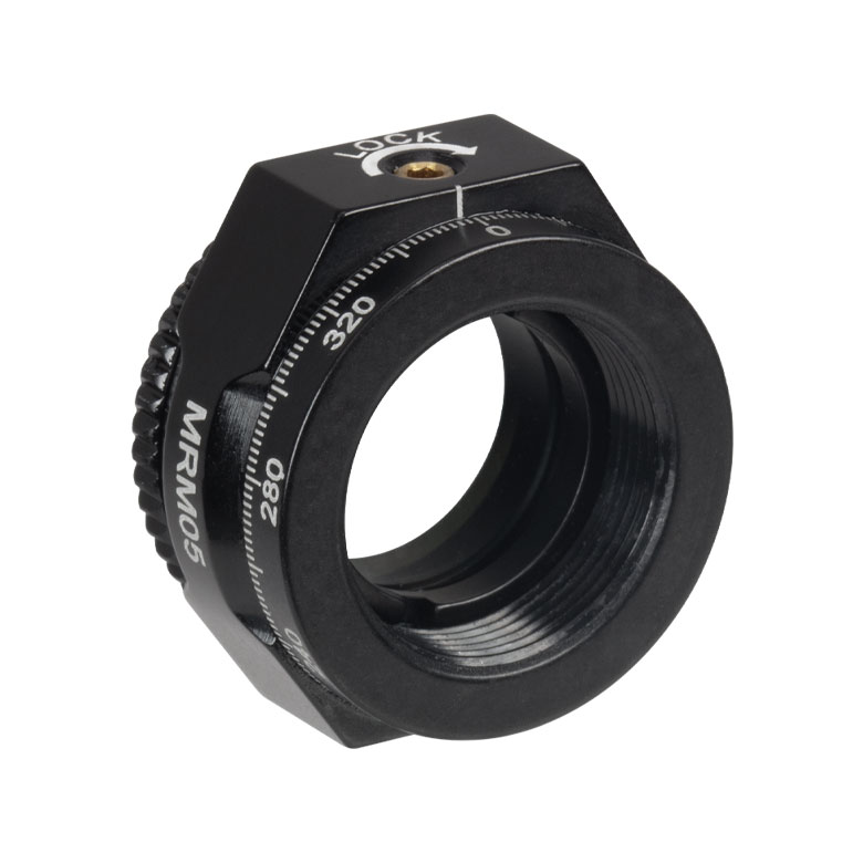 | 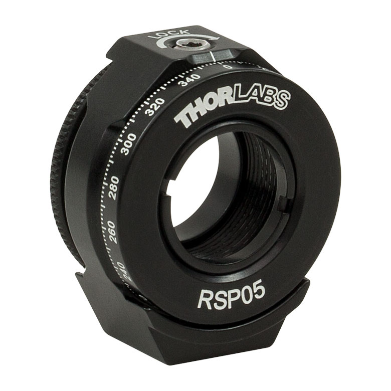 | 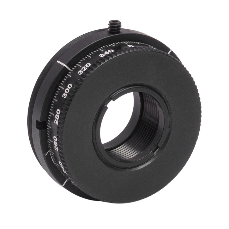 | 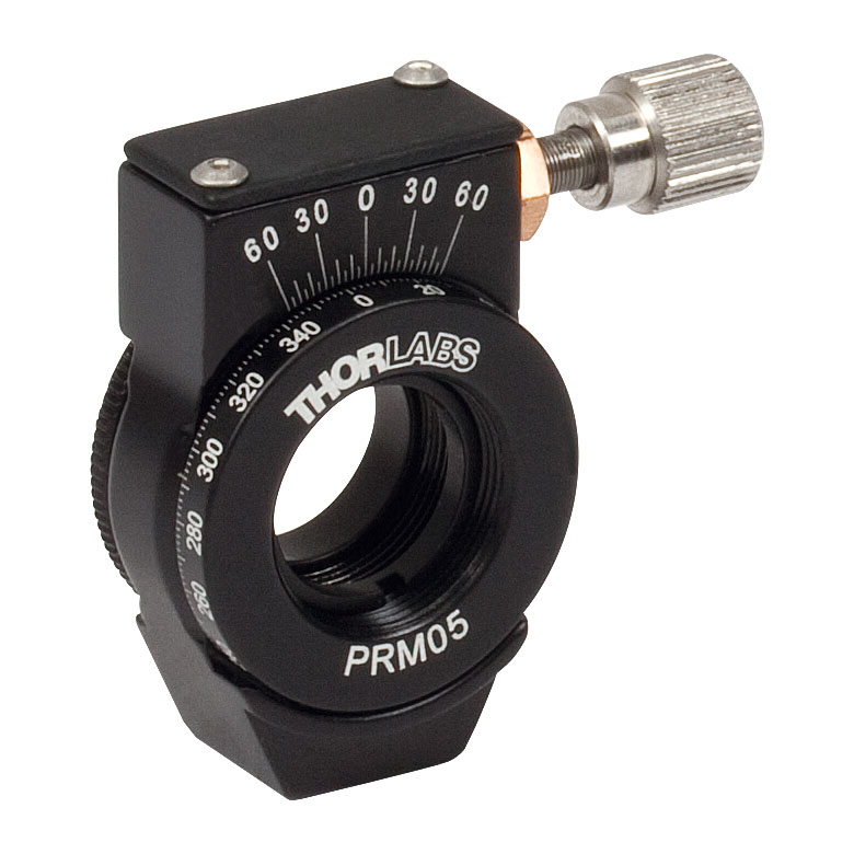 | 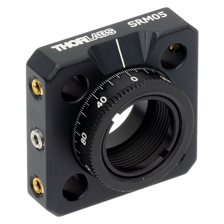 | 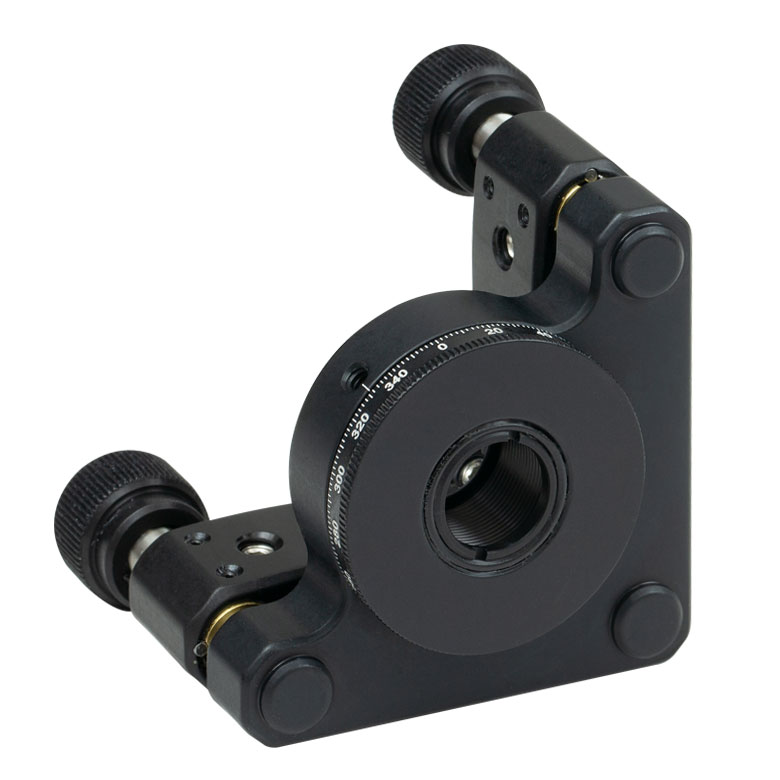 |  |
| Features | Mini Series | Standard | External SM1 (1.035"-40) Threads | Micrometer | 16 mm Cage-Compatible | ±4° Kinematic Tip/Tilt Adjustment Plus Rotation | Compatible with 30 mm Cage Translation Stages and 1/4" Translation Stagesb |
| Additional Details | |||||||
| Rotation Mounts for Ø1" Optics | ||||||||
|---|---|---|---|---|---|---|---|---|
| Item # | RSP1(/M) | LRM1 | RSP1D(/M) | DLM1(/M) | CLR1(/M) | RSP1X15(/M) | RSP1X225(/M) | PRM1(/M)a |
| Click Photo to Enlarge | 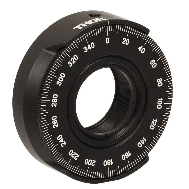 | 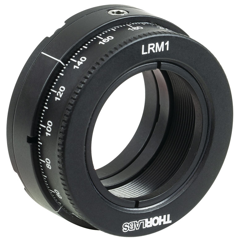 | 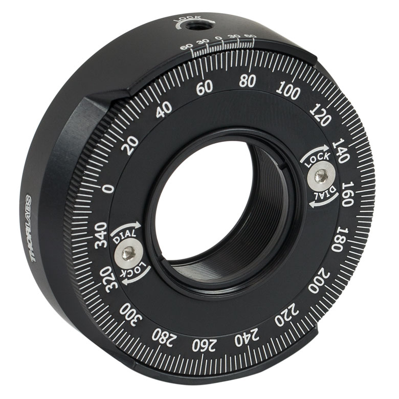 | 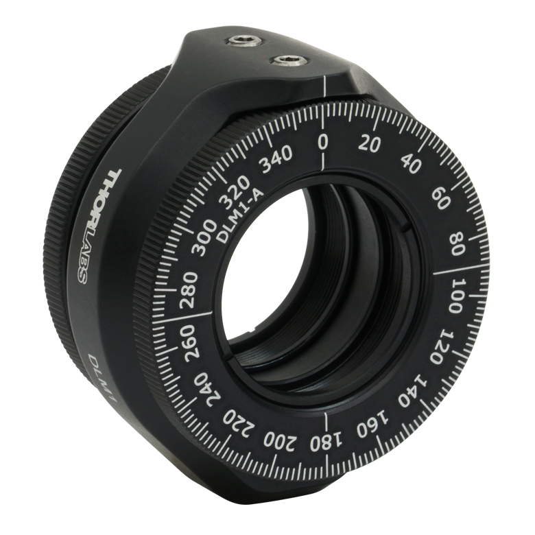 | 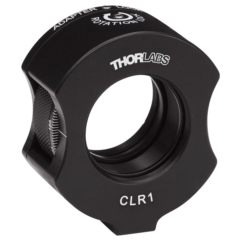 |  | | 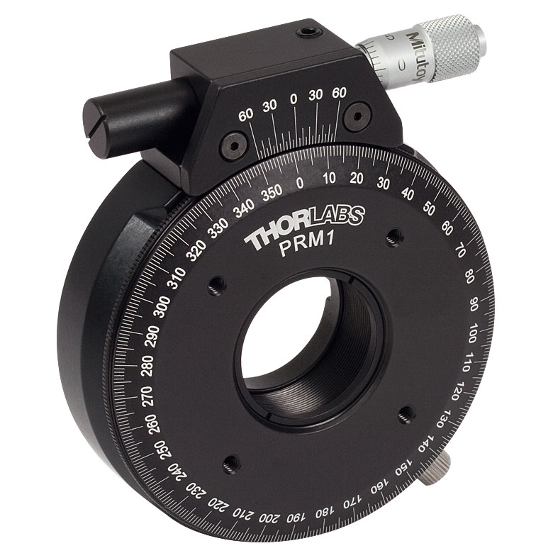 |
| Features | Standard | External SM1 (1.035"-40) Threads | Adjustable Zero | Two Independently Rotating Carriages | Rotates Optic Within Fixed Lens Tube System | Continuous 360° Rotation or 15° Increments | Continuous 360° Rotation or 22.5° Increments | Micrometer |
| Additional Details | ||||||||
| Rotation Mounts for Ø1" Optics | ||||||
|---|---|---|---|---|---|---|
| Item # | LM1-A & LM1-B(/M) | CRM1T(/M) | CRM1LT(/M) | CRM1PT(/M) | KS1RS | K6XS |
| Click Photo to Enlarge | 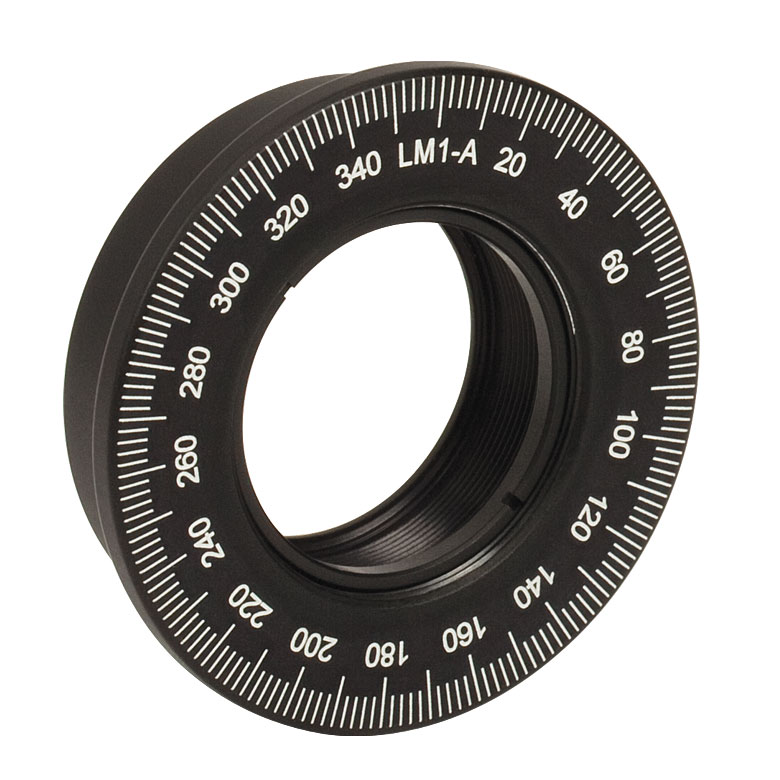 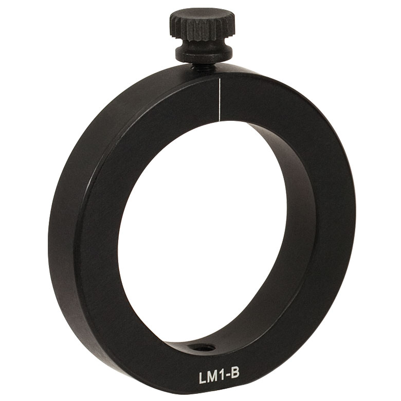 | 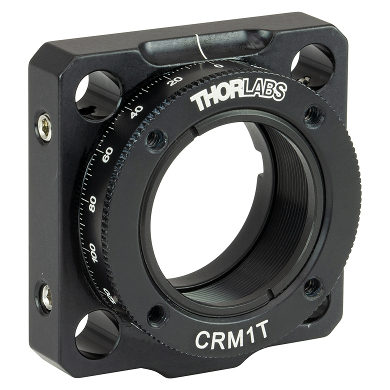 |  |  | 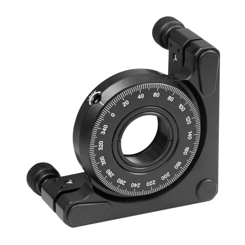 | 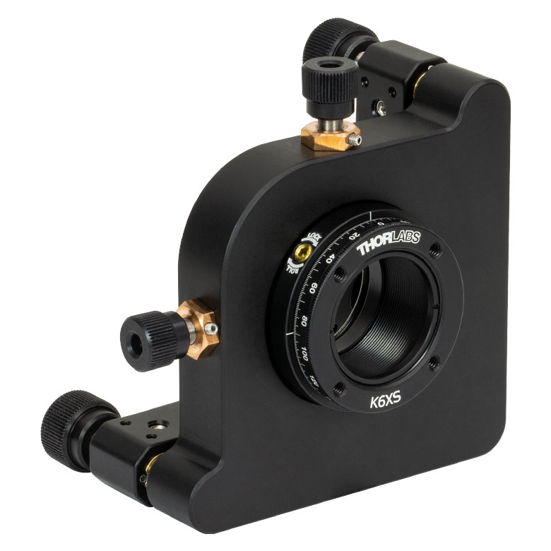 |
| Features | Optic Carriage Rotates Within Mounting Ring | 30 mm Cage-Compatiblea | 30 mm Cage-Compatible for Thick Opticsa | 30 mm Cage-Compatible with Micrometera | ±4° Kinematic Tip/Tilt Adjustment Plus Rotation | Six-Axis Kinematic Mounta |
| Additional Details | ||||||
| Rotation Mounts for Ø2" Optics | |||||||
|---|---|---|---|---|---|---|---|
| Item # | RSP2(/M) | RSP2D(/M) | PRM2(/M) | LM2-A & LM2-B(/M) | LCRM2(/M) | KS2RS | K6X2 |
| Click Photo to Enlarge | 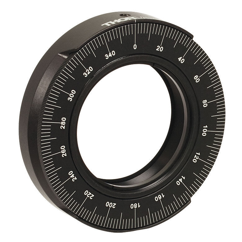 |  | 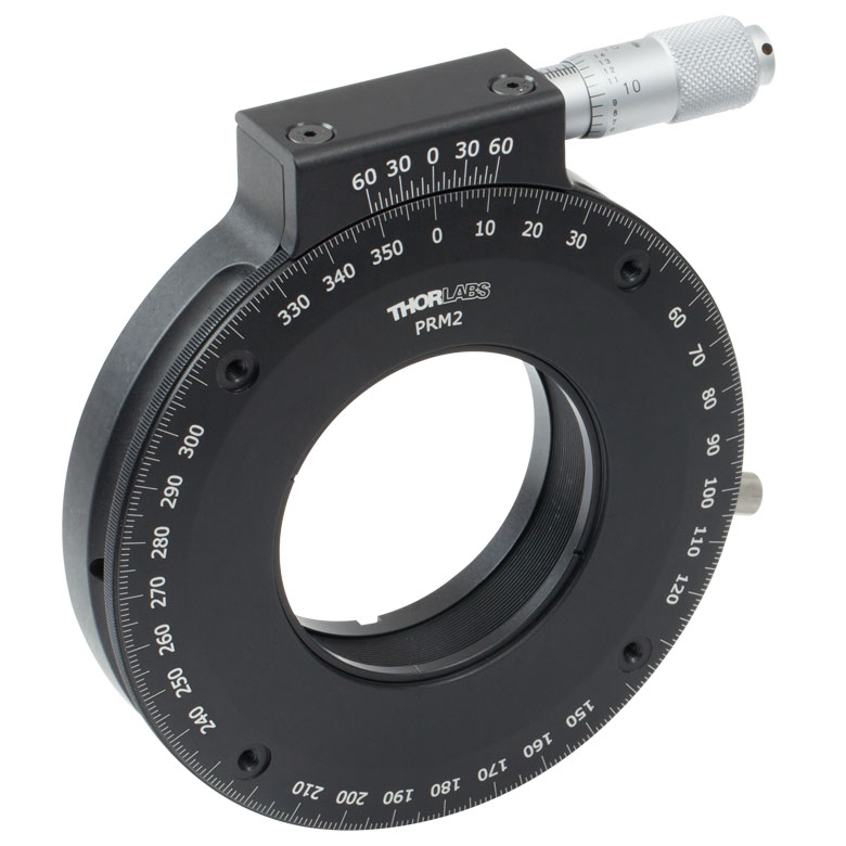 | 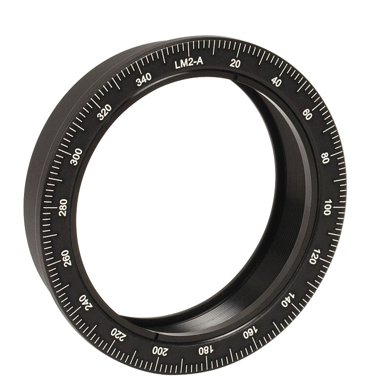 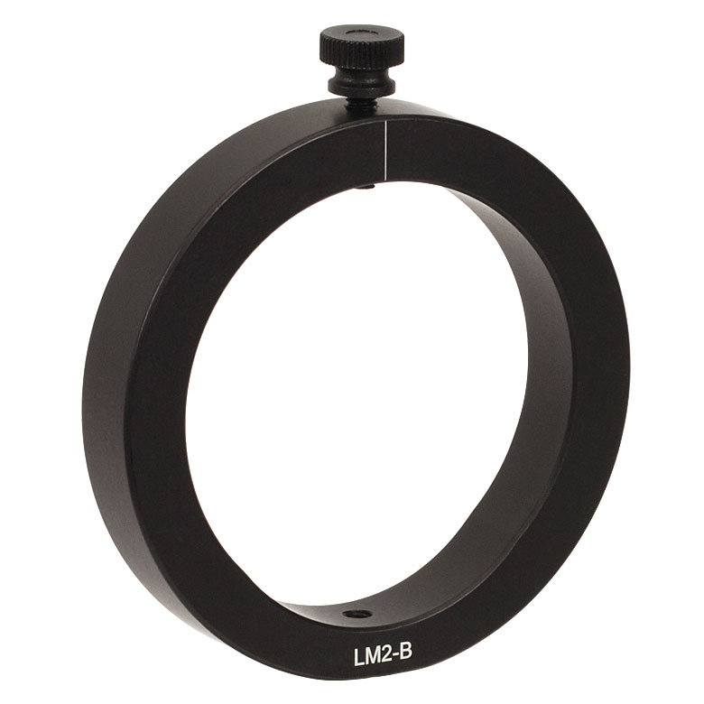 |  |  | 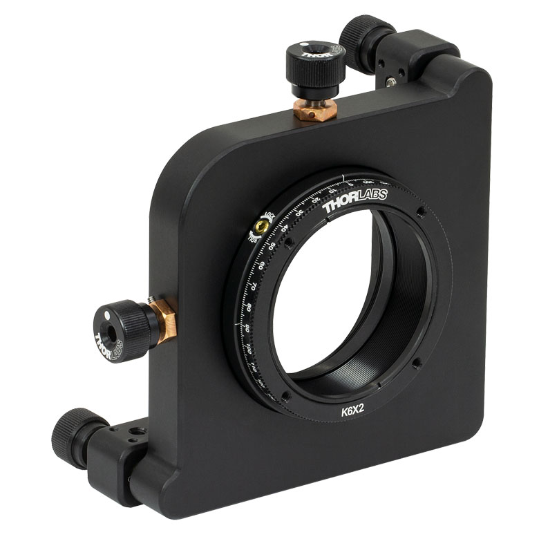 |
| Features | Standard | Adjustable Zero | Micrometer | Optic Carriage Rotates Within Mounting Ring | 60 mm Cage-Compatible | ±4° Kinematic Tip/Tilt Adjustment Plus Rotation | Six-Axis Kinematic Mount |
| Additional Details | |||||||
手動回転ステージ
| Manual Rotation Stages | ||||||
|---|---|---|---|---|---|---|
| Item # | RP005(/M) | PR005(/M) | MSRP01(/M) | RP01(/M) | RP03(/M) | QRP02(/M) |
| Click Photo to Enlarge | 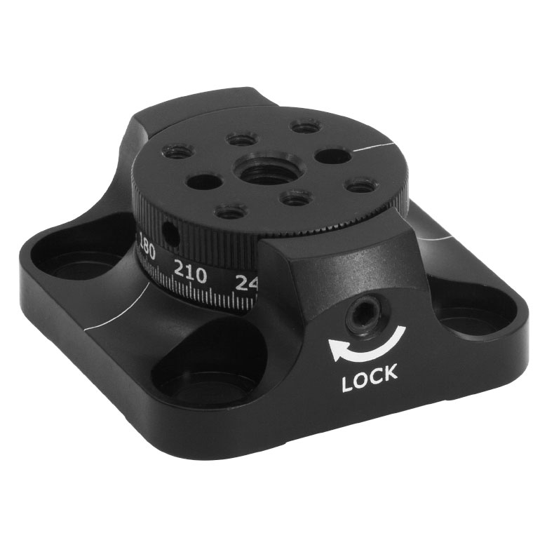 | 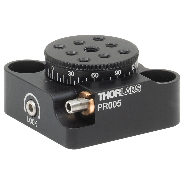 | 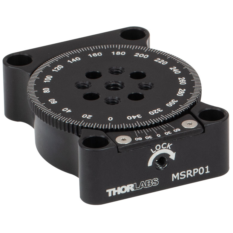 | 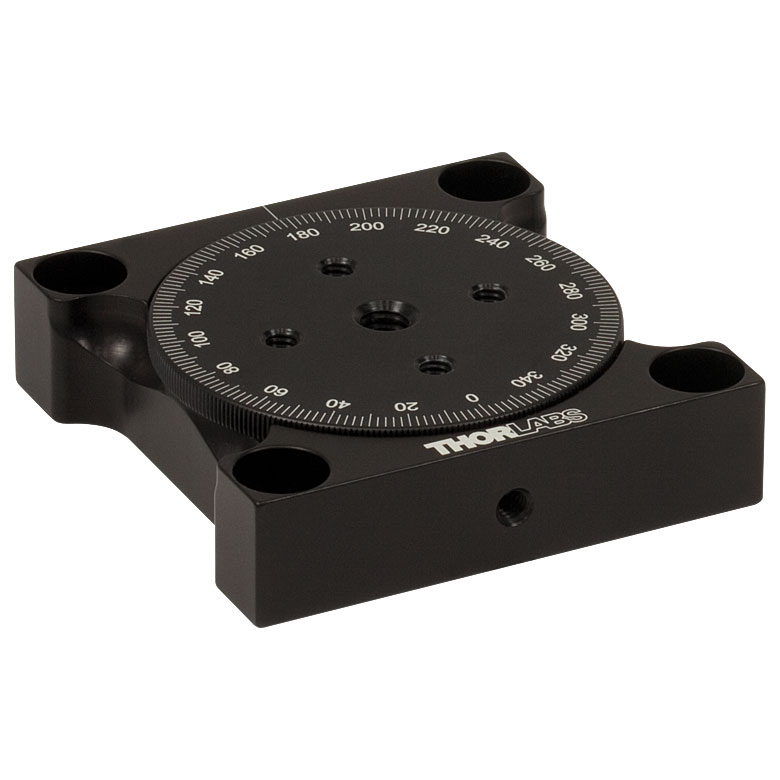 | 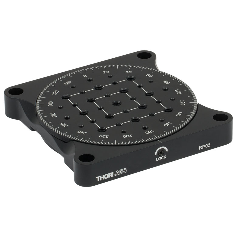 | 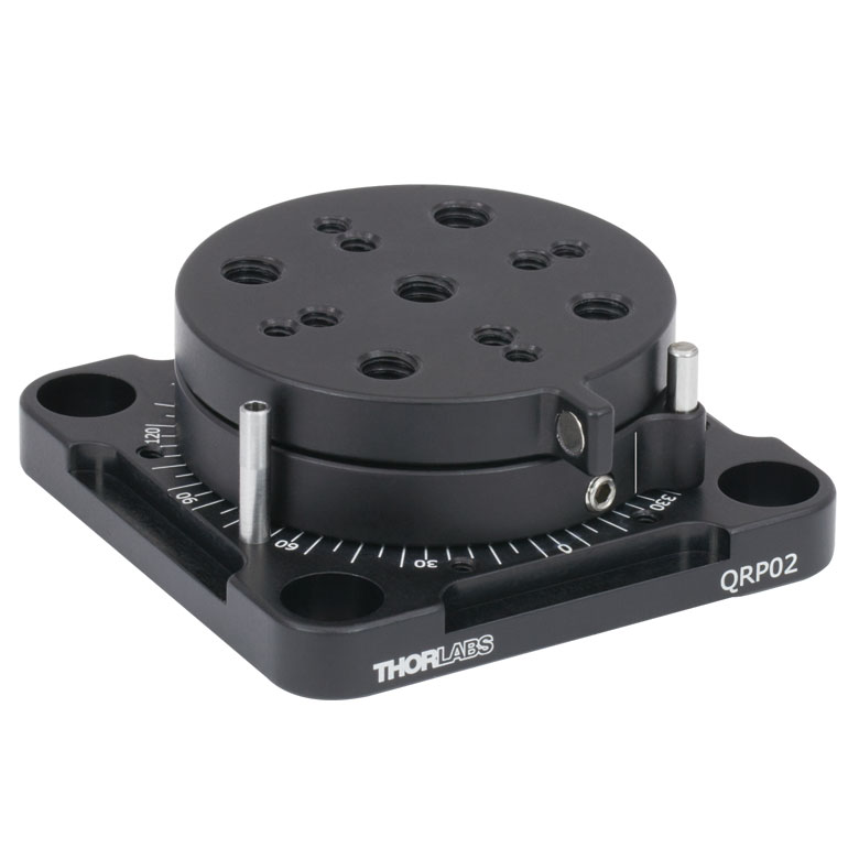 |
| Features | Standard | Two Hard Stops | ||||
| Additional Details | ||||||
| Manual Rotation Stages | ||||||
|---|---|---|---|---|---|---|
| Item # | XRNR1(/M) | XRR1(/M) | PR01(/M) | CR1(/M) | XYR1(/M) | OCT-XYR1(/M) |
| Click Photo to Enlarge | 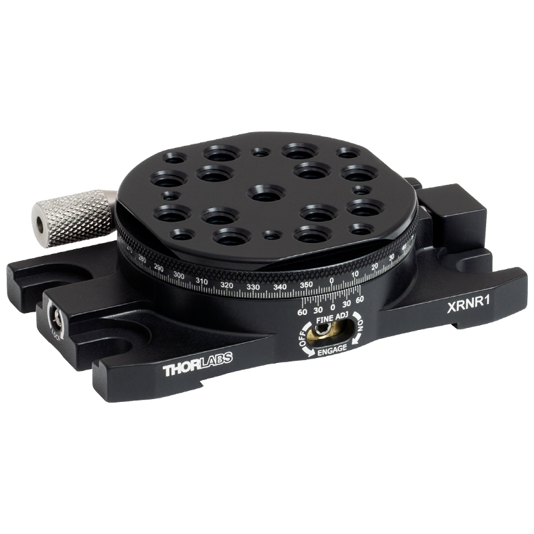 |  |  |  |  |  |
| Features | Fine Rotation Adjuster and 2" Wide Dovetail Quick Connect | Fine Rotation Adjuster and 3" Wide Dovetail Quick Connect | Fine Rotation Adjuster and SM1-Threaded Central Aperture | Fine Pitch Worm Gear | Rotation and 1/2" Linear XY Translation | |
| Additional Details | ||||||
電動回転マウント&ステージ
| Motorized Rotation Mounts and Stages with Central Clear Apertures | |||||
|---|---|---|---|---|---|
| Item # | DDR25(/M) | PDR1C(/M) | PDR1(/M) | PDR1V(/M) | PDXR1(/M) |
| Click Photo to Enlarge |  |  |  |  |  |
| Features | Compatible with SM05 Lens Tubes, 16 mm Cage System, & 30 mm Cage System | Compatible with 16 mm Cage System | Compatible with SM05 Lens Tubes & 30 mm Cage System | Vacuum-Compatible; Also Compatible with SM05 Lens Tubes & 30 mm Cage System | Compatible with SM05 Lens Tubes & 30 mm Cage System |
| Additional Details | |||||
| Motorized Rotation Mounts and Stages with Central Clear Apertures | |||||
|---|---|---|---|---|---|
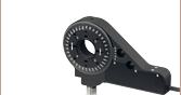
| Item # | K10CR1(/M) | PRM1Z8(/M)a | DDR100(/M) | ELL14 | HDR50(/M) |
| Click Photo to Enlarge |  | 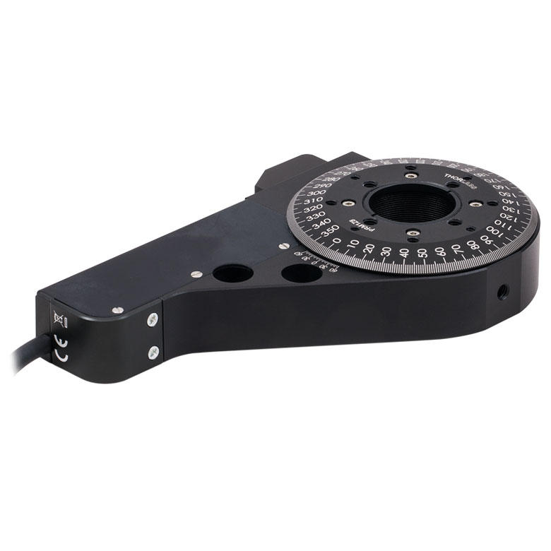 | 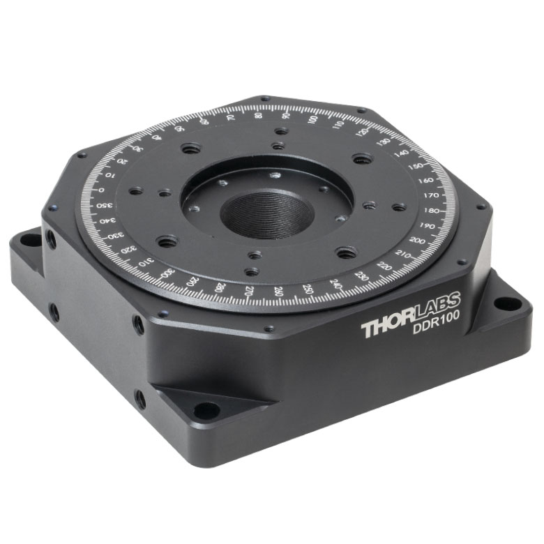 | 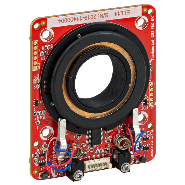 | 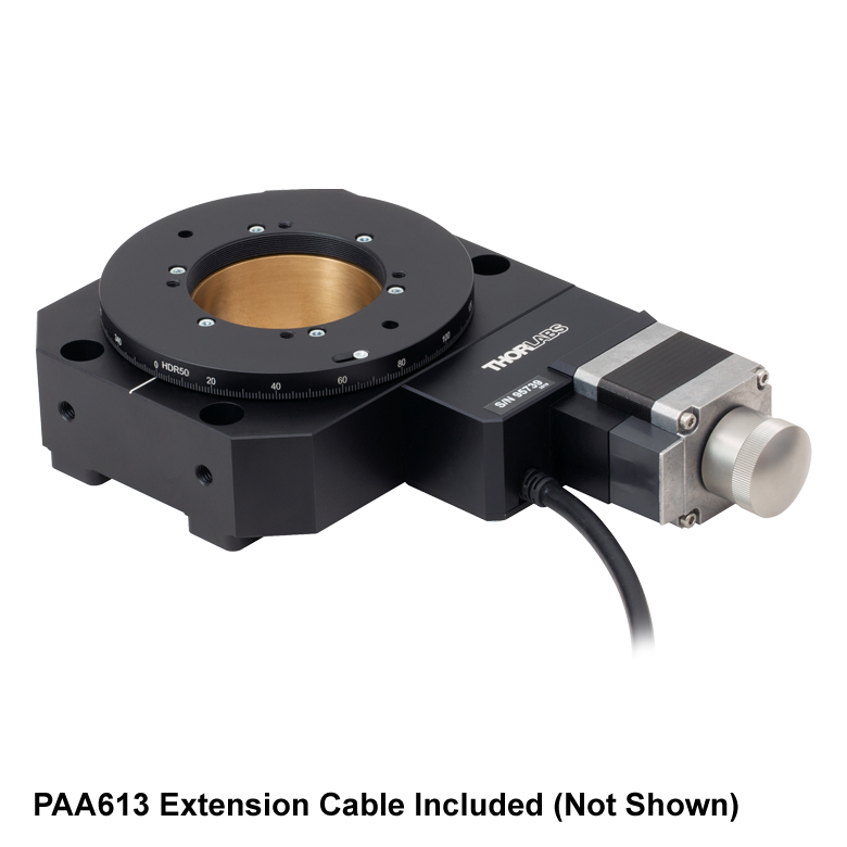 |
| Features | Compatible with SM1 Lens Tubes & 30 mm Cage System | Compatible with SM1 Lens Tubes, 16 mm Cage System, 30 mm Cage System | Compatible with SM1 Lens Tubes, Open Frame Design for OEM Applications | Compatible with SM2 Lens Tubes | |
| Additional Details | |||||
| Motorized Rotation Mounts and Stages with Tapped Platforms | ||
|---|---|---|
| Item # | PRMTZ8(/M)a | ELL18(/M)b |
| Click Photo to Enlarge |  | 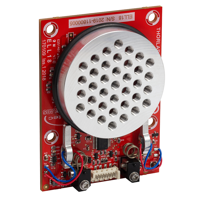 |
| Features | Tapped Mounting Platform for Mounting Prisms or Other Optics | Tapped Mounting Platform, Open Frame Design for OEM Applications |
| Additional Details | ||

 ズーム
ズーム
Click to Enlarge
モータのアルミニウム製先端は、回転マウントの周りを取り囲む黒いプラスチック製のトラックに接触しています。このトラックには、埃や油を付着させないために、触らないようにご注意ください。
- 製品組み込み(OEM)のための事前評価試験に適した製品
- セットアップへの組み込みが容易
- 手動やPC制御で操作
- マウントへの電力供給には付属の電源が必要
回転マウントセットは回転マウントELL14を含む一式のパッケージです。パッケージELL14Kを使用することで、回転マウントを実験セットアップや様々なアプリケーションに容易に組み込むことができます。また、この技術を製品へ組み込み可能かどうか判断する際に活用いただくこともできます。
2つのモータの先端は、右端の写真のように、回転マウントの周りを取り囲むゴム製のトラックにしっかりと接触しています。モータは互いに反対の回転方向に向けて取り付けられており、一方のモータがトラックを押し、もう一方のモータが反対方向に引っ張るときに、時計回り(または反時計回り)に回転します。
| Included in the ELL14K Bundle | |
|---|---|
| ELL14 Rotation Mount | 5 V Power Supply with Region-Specific Power Adapter |
| Interface Board | 8-Conductor 28 AWG Ribbon Cable |
| USB Cable | PC-Based Software for Download |

 ズーム
ズームClick to Enlarge
回転マウントの概要図
こちらの回転マウントは、Elliptec®共振モータを用いた複数の製品のネットワークを必要とするアプリケーション用に適しています。Ø25 mm~Ø25.4 mm(Ø1インチ)光学素子を保持するためのSM1ネジ付きマウントが付いています。寸法や取付穴の間隔を含め、マウントの詳細仕様については「仕様」タブをご覧ください。回転マウントのカスタマイズについては当社までお問い合わせください。
回転マウントのPCB基板にはオス型の8ピンPicoflex®コネクタ(ヘッダ)が付いています。マウントELL14には基板のコネクタ(ヘッダ)に結合するメス型の8ピンPicoflexコネクタ(レセプタクル)が付属します。

 ズーム
ズーム| Specifications | ||
|---|---|---|
| Item # | ELLC2 | |
| DC Voltage Input to Controller | 4.5 to 5.5 V | |
| Typical Current Consumption Per Module | Movement | 800 mA |
| Standby | 50 mA | |
| Operating Temperature Range | 15 to 40 °C | |
| Ribbon Cable Length (1 Included) | 250 mm (9.84") | |
| Maximum Supported Ribbon Cable Length | 500 mm (19.68") | |
| Dimensions (Interface Only) | 66.0 mm x 32.0 mm x 12.5 mm (2.60" x 1.26" x 0.49") | |
| Weight (Interface Only) | 10.8 g (0.022 lbs) | |
- 単品のELLシリーズ製品に追加して1組のキットを構成するための下記のコンポーネントのセット
- ハンドヘルドコントローラ
- USB Micro Bケーブル
- Picoflex®1ケーブル
- 5 V電源、国内対応アダプタ
アップグレード用アクセサリーキットELLC2は、単品のELLシリーズのスライダ、ステージ、マウントをお持ちの場合に、それに追加して上記のようなELLセット一式2とするためのコンポーネントを揃えたキットです。接続されたELLステージの位置は、付属のハンドヘルドコントローラの3つのボタンで制御することができます。またUSBポートと付属のUSB Micro Bケーブルを介して、PCと直接接続することができます。キットには、ハンドヘルドコントローラとELLデバイスを接続するための0.25 mのPicoflex®ケーブル(8負荷回路)と、5 V電源(国内対応アダプタ付き)も含まれています。
- 注: Picoflex®はMolex社の登録商標です。
- ELL17/M、ELL18/MおよびELL20/M用の取付けブラケットのご注文は当社までご連絡ください。

 ズーム
ズーム| Specifications | ||
|---|---|---|
| Item # | ELLB | |
| Voltage Rating | 4.5 to 5.5 V | |
| Typical Current Consumption Per Module | Movement | 800 mA |
| Standby | 50 mA | |
| Maximum Board Current | 4.0 A | |
| Operating Temperature Range | 15 to 40 °C | |
| Ribbon Cable Length (4 Included) | 250 mm | |
| Maximum Supported Ribbon Cable Length | 500 mm | |
| Dimensions | 65.0 mm x 32.0 mm x 12.5 mm (2.56" x 1.26" x 0.49") | |
| Weight | 11 g (0.02 lbs) | |
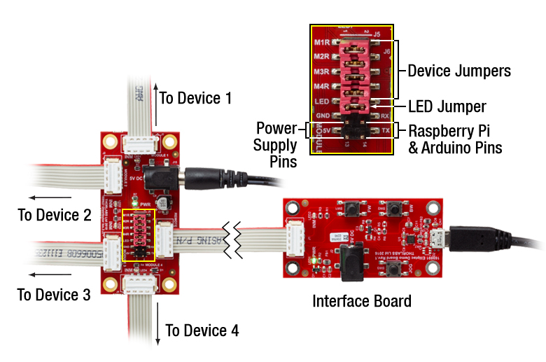
Click to Enlarge
1個のバス分配器で最大4個のElliptecデバイスを制御できます。バスは上記のセットに付属しているインターフェイスボードでPCに接続可能です。このときバスはElliptecソフトウェアによって制御され、インターフェイスボード上のボタンは無効になっていますのでご注意ください。
- 1つのバスで最大4台までのElliptec®デバイスに対する制御と電源供給が可能
- 分配器をデイジーチェーン接続すると最大16台までのElliptecデバイスを制御可能
- Elliptecシステムソフトウェア(上記の「ソフトウェア」タブ参照)によるリモート制御
- Elliptec製品のセットに付属するUSBインターフェイスボードを使用してPCに接続可能
- ジャンパ5個およびリボンケーブル(8芯、AWG28)4本が付属
- Raspberry Pi®とArduino®ボードにも対応
バス分配器ELLBには、最大4台までのElliptec®デバイスを接続できます。 接続されたデバイスは上記のセットに付属するインターフェイスボードで制御可能ですが、それが無くても制御できます。インターフェイスボードを使用する場合は、接続された各デバイスはElliptecソフトウェアパッケージが動作するPCによってリモート制御されます。インターフェイスボードは、分配器のREMOTEと記載されているバス信号の入力ポートに接続します。この接続を行うと、インターフェイスボードのボタンは無効になります。インターフェイスボードを使用せずにカスタム接続する場合は、「ピン配列」タブをご覧ください。
複数のバス分配器ELLBをデイジーチェーン接続すると、最大16台までのElliptecデバイスに対する制御と電源供給が可能になります。単純に4つの出力ポート(MODULE)の内の1つを、次のボードの入力ポート(REMOTE)に接続するだけで動作します。LEDインジケータによりどのデバイスが動作しているかが示されます。ソフトウェアで各デバイスを個別にアドレス指定する方法については、通信プロトコルマニュアルをご参照ください。ソフトウェアと付属文書のダウンロードリンクは「ソフトウェア」タブにございます。
バス分配器には、最大電流4 Aの5 V電源を接続するためのØ6.3 mm電源コネクタが付いています。より多くのデバイスを接続して各ユニットを同時に制御するには、電源からより多くの電流を供給する必要があります。 各Elliptecデバイスによって消費される電流については、「仕様」タブをご覧ください。5V、2 Aの電源が上記ELL9およびELL12に付属しています。接続されたElliptecデバイスの消費電流に応じて、電源は同時に2つのデバイスに対して電流の供給ができます。
機能を追加するための制御ピンが14個付いています(右の写真参照)。ピンの4組のペアがそれぞれジャンパで短絡されているとき、つまりジャンパがセットされているときは、Elliptecソフトウェアは接続されたElliptecデバイスからのフィードバック信号を受信することができます。 LEDと記載されているピンのペアはジャンパで短絡されていますが、これを取り外すとLEDインジケータは無効になります。 5VとGNDと記載されたピンを用いると、Ø6.3 mm電源コネクタに接続された電源の代わりに、お手持ちの5 V、2 A 電源を使用することができます。 RX とTX と記載されたピンを用いると、Elliptecインターフェイスボードの代わりに、Raspberry Pi®やArduino®ボードでバスを制御することができます。
ボードは四隅にあるØ3.5 mm貫通穴を使用して取り付けます。リボンケーブル(8芯、AWG28)は4本付属します。
| Compatible Elliptec Devices | |||||
|---|---|---|---|---|---|
| | | |  | |
| Multi-Position Sliders | 28 mm Linear Stage | 60 mm Linear Stage | Rotation Stage | Rotation Mount | Motorized Iris |