 Products Home / 半導体レーザ用電流コントローラ(LDドライバ)、温度コントローラ、LDマウント / 組み込み用半導体レーザー(LD)ドライバー/コントローラー / 組み込み用半導体レーザードライバー、定出力
組み込み用半導体レーザードライバー、定出力
- Constant Power
- APC Laser Driver, 0 - 250 mA
- Driver Kits Pre-Wired to Styles A & B
LD1100
LD1101
EK1102


Please Wait

| Item# | LD1100 | LD1101 | EK1101a | EK1102b |
|---|---|---|---|---|
| Output Current | 0 - 250 mA | |||
| Supported Laser Pin Configurations | A, B, D, & F | C, D, & F | A | B |
| Recommended for LEDsb | No | No | Yes | Yes |
| Output Control | 12-Turn Power Adjustment (On-Board) | |||
| Output Stability | 1.5% | |||
| Output Noise | 5 μA RMS | |||
| Feedback Gain | Adjustable | |||
| Monitor Current Range | 5 μA to 5 mA | |||
| Operating Voltage | 8 to 12 VDC | |||
| Quiescent Current | 9 mA | |||
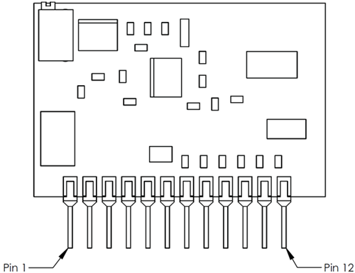
| Dimensions | 1" x 1.5" 12-Pin SIP Package | See Drawing | ||
| ESD Protection | 100 ms Slow Start | |||
| Max Output Voltage | ~6.5 V (with a 12 V Power Supply) | |||
半導体レーザードライバ
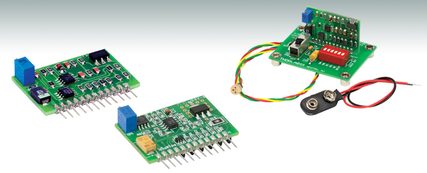
半導体レーザードライバLD1100、LD1101は、レーザを定出力駆動するドライバーモジュールで、アノードコモンやカソードコモンのピン配列を有する半導体レーザに対応しています。レーザ出力パワーを連続調整するための基板上12回転トリムポット、プログラム可能なフィードバック利得、on/off制御入力、レーザ駆動電流を測定するための電流モニタ出力が備わっています。25.4 mm×38.1 mmの小型サイズのため、機器に組み込むことができます。LD1100およびLD1101の最大出力電圧は、12 Vの電源を使ったときに約6.5 Vです。すべての入力および出力信号は、プリント回路への組込みが容易な12ピンSIPコネクタを通して供給されます。
LD1100およびLD1101は定出力モードで、最大250 mAの駆動電流を供給できます。これらのドライバでは、比例-積分コントローラ用のフィードバック信号としてモニタ用フォトダイオードが内蔵されており、出力パワーを1.5 %以内に安定させています。広範囲な半導体レーザに合わせるために、5つの利得設定用抵抗ピンのいずれかをジャンパを使って電源に接続することによって、フィードバック利得をプログラムすることができます。これによって、モニタ電流が5 μA~5 mAのレーザを1台のドライバで使用することができます。
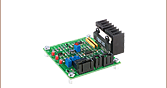
評価キット
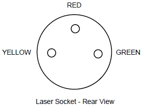
EK1100シリーズの評価キットは、フィードバック信号の利得を制御するためのディップスイッチ列とon/offスイッチを持つプリント回路基板(PCB)にはんだ付けされた半導体レーザードライバLD1100で構成されています。3ピンレーザーソケットケーブル(S8060)も、PCBボードにはんだ付けされています(このソケットによって、このキットが使えるピン配列が決まります)。半導体レーザを駆動することに加えて、EK1101とEK1102は、それぞれスタイルAまたはスタイルBのピン配列を持つモニタ用フォトダイオードを含むLEDを動作させることも可能です。
電源オプション
9 V電源用ケーブルが付属していますが、接続はされていません。
外観について
ドライバLD1100およびLD1101のボード上の部品は上の写真と異なる場合があります。写真と異なる場合でもここで説明する電気仕様ならびに動作仕様に適合しています。
対応するピン配置
LD1100のピン配置
| Pin | Signal | Description |
|---|---|---|
| 1 | +V | Circuit Power, 8 to 12 VDC, 9 mA + Laser Drive Current NOTE: Internally tied to Laser Diode Anode, the laser anode must be isolated from the power supply COM |
| 2 | COM | Circuit Ground |
| 3 | VREF | Internal 2.5 V reference |
| 4 | PDA | Photodiode Anode |
| 5 | LDA | Laser Diode Anode (Internally Tied to +V (Pin 1)) |
| 6 | LDC | Laser Diode Cathode |
| 7 | RA | When Tied to Common, Puts 100 kΩ in Parallel with 249 kΩ Internal Gain Resistor |
| 8 | RB | When Tied to Common, Puts 33.2 kΩ in Parallel with 249 kΩ Internal Gain Resistor |
| 9 | RC | When Tied to Common, Puts 10 kΩ in Parallel with 249 kΩ Internal Gain Resistor |
| 10 | RD | When Tied to Common, Puts 3.32 kΩ in parallel with 249 kΩ Internal Gain Resistor |
| 11 | RE | When Tied to Common, Puts 1 kΩ in Parallel with 249 kΩ Internal Gain Resistor |
| 12 | ILD | Laser Diode Current Monitor (10 mV/mA) |
LD1101のピン配置
| Pin | Signal | Description |
|---|---|---|
| 1 | +V | Circuit Power, 8 to 12 VDC, 9 mA + Laser Drive Current NOTE: Internally tied to Laser Diode Anode. The laser anode must be isolated from the power supply COM. |
| 2 | COM | Circuit Ground |
| 3 | VREF | Internal 2.5 V reference |
| 4 | PDC | Photodiode Cathode |
| 5 | LDA | Laser Diode Anode (Internally Tied to +V (Pin 1)) |
| 6 | LDC | Laser Diode Cathode |
| 7 | RA | When Tied to Pin 6, Puts 5 kΩ in parallel with 12.4 kΩ Internal Gain Resistor |
| 8 | RB | When Tied to Pin 6, Puts 1.5 kΩ in parallel with 12.4 kΩ Internal Gain Resistor |
| 9 | RC | When Tied to Pin 6, Puts 499 Ω in parallel with 12.4 kΩ Internal Gain Resistor |
| 10 | RD | When Tied to Pin 6, Puts 160 Ω in parallel with 12.4 kΩ Internal Gain Resistor |
| 11 | RE | When Tied to Pin 6, Puts 33 Ω in parallel with 12.4 kΩ Internal Gain Resistor |
| 12 | ILD | Laser Diode Current Monitor (10 mV/mA) |
EK1101
レーザーアノード:フォトダイオードカソードコモン
| Laser Pin | J1 Pin (on Evaluation Board) | Wire Color |
|---|---|---|
| PDA | PD_A | Green |
| LDA/PDC | LD_A | Red |
| LDC | LD_C | Yellow |
EK1102
レーザーカソード:フォトダイオードカソードコモン
| Laser Pin | J1 Pin (on Evaluation Board) | Wire Color |
|---|---|---|
| PDA | PD_A | Green |
| LDA | LD_A | Yellow |
| LDC/PDC | LD_C | Red |
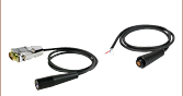
EK110x レーザーソケットワイヤーハーネス
Click to Enlarge
EK1101 Packaging

Smart Pack
- Reduce Weight of Packaging
- Increase Usage of Recyclable Materials
- Improve Packing Integrity
- Decrease Shipping Costs
Thorlabs' Smart Pack Initiative is aimed at minimizing waste while providing adequate protection for our products. By eliminating any unnecessary packaging, implementing design changes, and utilizing eco-friendly materials, this initiative seeks to reduce the environmental impact of our product packaging.
The updated EK1101 and EK1102 packaging primarily consists of recycled paper and cardboard and weighs 19.70% less than the original packaging. This weight change results in a 3.79 kg reduction in travel-based CO2 emissions per year, based on typical product sales.
As we move through our product line, we will indicate re-engineered, eco-friendly packaging with our Smart Pack logo, which can be seen above.
| Posted Comments: | |
DH Yi
(posted 2023-12-15 18:48:16.27) Today I get EK1101/ EK1102
I connect L650P007 with EK1101
(650nm, 7mW, A Pin code)
But, It is not work correct.
Can you guide me ? ksosnowski
(posted 2023-12-18 12:46:03.0) Thanks for reaching out to Thorlabs. I would first check the LD1100 pinout against your laser to ensure no connections are mixed up. The driver manual has a list of gain resistor settings that can be selected by jumping to ground to accommodate different monitor current levels. For issues like this you can contact us directly at techsupport@thorlabs.com. I have reached out to discuss this application further. Philip Cooke
(posted 2023-06-30 12:36:02.0) Hello,
I ordered the LD1100 for some development projects, and I wanted to connect some additional external circuitry.
Can you please email me the schematic of the board so I can find the best electrical connection point?
Thank you
Phil cdolbashian
(posted 2023-07-13 02:28:28.0) Thank you for reaching out to us with this inquiry, and for your interest in our products. Unfortunately we cannot share the explicit circuit diagram with you for this product. That being said, we have contacted you directly in order to assist you in finding a solution to your inquiry without sharing the full circuit diagram with you. Yu-Xuan Wu
(posted 2021-01-27 18:01:26.757) Hello!
I found that our 405 nm laser(DL-5146-101S) which is driven by EK1102 encountered a problem.
The power of the laser was consistently rising(sometimes falling).
Would it be helpful using the temperature controller?
Or do you have any other suggestion? YLohia
(posted 2021-02-16 02:18:15.0) Hello, thank you for contacting Thorlabs. We had reached out to you with a few troubleshooting questions, but we didn't hear back. Over what time scale does this fluctuation occur? How are you measuring the power? Are there any other optical components between the laser and your power sensor? Have you checked for an eliminated back-reflections into the laser cavity? Are you able to monitor the laser current and the monitor photodiode current? Do they fluctuate the same amount as your laser power? Justin Molloy
(posted 2019-09-12 09:54:30.837) I have made a simple "hack" to enable computer control of power using this driver. If you would like to see the small modification required and/or would like the Arduino code for manual rotary encoder power control and ability to control via RS232 please feel free to contact me. There would be NO Warranty at all and I accept no liability for any faults in design/software etc - i.e. use entirely at your own risk! YLohia
(posted 2019-09-12 12:59:25.0) Hello Justin, thank you for contacting Thorlabs and offering us this code. I have added this to our internal knowledge base with due credit to you. We believe the rest of our customer base will really appreciate this as well.
This code can now be requested by our other customers by emailing techsupport@thorlabs.com. mitch
(posted 2016-08-11 03:48:19.71) Hi, is it possible to use the LD1100 to bias a VCSEL? jlow
(posted 2016-08-15 10:31:03.0) Response from Jeremy at Thorlabs: This board is not recommended for VCSEL by itself. You could use it in conjunction with our T1G bias-T PCB for pulsed operation. We also have VCSEL drivers at https://www.thorlabs.com/newgrouppage9.cfm?objectgroup_id=1377. x.attendu
(posted 2016-06-27 12:53:28.85) Hi,
I would like to know if it would be possible to drive multiple laser diodes simultaneously with this product. The idea would be to connect 3 different laser diodes in parallel each with a laser diode bias tee to modulate their currents separately. Would this work or am I going to fry the driver ? Thank you for your time. jjurado
(posted 2011-04-06 16:59:00.0) Response from Javier at Thorlabs to li.li: Thank you for contacting us with your request. The change in driving current is a result of heating of the laser diode. The EK1102 is a constant power laser diode driver, and, as the diode heats up and loses efficiency, the driver injects more current in order to keep the power output constant. If the diode has a relatively high operating current, and if the experiment requires the diode to be turned on for extended periods of time, it is recommended to provide temperature control in order to prevent potential damage. If passive heat dissipation by a heatsink is not enough, then it would be recommended to use a thermoelectric cooler. You can find our offerings through the following link:
http://www.thorlabs.com/NewGroupPage9.cfm?ObjectGroup_ID=305
I will contact you directly in case you have additional questions. li.li
(posted 2011-04-06 13:43:11.0) The LD driving current is increasing with time. Is it caused by the temperature of laser diode? Shall I set a maximum driving current for the laser diode through the EK1102, otherwise Im affraid the diode laser will be damaged. Probably I need a Peltier cooler, could you please recommend me some products for the laser diode cooler? Thank you for your time. Tyler
(posted 2009-01-08 16:44:18.0) A response from Tyler at Thorlabs to melsscal: This modification can be made. I will have a member of our technical support department contact you. They can create a quote for the modified part. melsscal
(posted 2009-01-08 06:45:59.0) Can you arrange to make a connector for connecting the LDS2 to EK1101 ?
Regards
A.K.Bose
MELSS
KOLKATA/INDIA
melsscal@melss.com |
半導体レーザーコントローラーセレクションガイド
Table 137Aと137B は、当社の半導体レーザ用コントローラおよびデュアル半導体レーザ/温度コントローラの主な仕様の一覧です。詳しい内容や仕様について、またはご注文の際には表内の型番をクリックしてご確認ください。
| Table 137A Current Controllers | ||||||
|---|---|---|---|---|---|---|
| Item # | Drive Current | Compliance Voltage | Constant Current | Constant Power | Modulation | Package |
| LDC200CV | 20 mA | 6 V | External | Benchtop | ||
| VLDC002 | 25 mA | 5 V | - | Int/Ext | OEM | |
| LDC201CU | 100 mA | 5 V | External | Benchtop | ||
| LD2000R | 100 mA | 3.5 V | - | External | OEM | |
| EK2000 | 100 mA | 3.5 V | - | External | OEM | |
| LDC202C | 200 mA | 10 V | External | Benchtop | ||
| KLD101 | 230 mA | ≤10 V | External | K-Cube® | ||
| IP250-BV | 250 mA | 8 Va | External | OEM | ||
| LD1100 | 250 mA | 6.5 Va | - | -- | OEM | |
| LD1101 | 250 mA | 6.5 Va | - | -- | OEM | |
| EK1101 | 250 mA | 6.5 Va | - | -- | OEM | |
| EK1102 | 250 mA | 6.5 Va | - | -- | OEM | |
| LD1255R | 250 mA | 3.3 V | - | External | OEM | |
| LDC205C | 500 mA | 10 V | External | Benchtop | ||
| IP500 | 500 mA | 3 V | External | OEM | ||
| LDC210C | 1 A | 10 V | External | Benchtop | ||
| LDC220C | 2 A | 4 V | External | Benchtop | ||
| LD3000R | 2.5 A | -- | - | External | OEM | |
| LDC240C | 4 A | 5 V | External | Benchtop | ||
| LDC4005 | 5 A | 12 V | Int/Ext | Benchtop | ||
| LDC4020 | 20 A | 11 V | Int/Ext | Benchtop | ||
| Table 137B Dual Temperature and Current Controllers | |||||||
|---|---|---|---|---|---|---|---|
| Item # | Drive Current | Compliance Voltage | TEC Power (Max) | Constant Current | Constant Power | Modulation | Package |
| VITC002 | 25 mA | 5 V | >2 W | - | Int/Ext | OEM | |
| ITC102 | 200 mA | >4 V | 12 W | Ext | OEM | ||
| ITC110 | 1 A | >4 V | 12 W | Ext | OEM | ||
| ITC4001 | 1 A | 11 V | >96 W | Int/Ext | Benchtop | ||
| CLD1010LPa | 1.0 A | >8 V | >14.1 W | Ext | Benchtop | ||
| CLD1011LPb | 1.0 A | >8 V | >14.1 W | Ext | Benchtop | ||
| CLD1015c | 1.5 A | >4 V | >14.1 W | Ext | Benchtop | ||
| ITC4002QCLd | 2 A | 17 V | >225 W | Int/Ext | Benchtop | ||
| ITC133 | 3 A | >4 V | 18 W | Ext | OEM | ||
| ITC4005 | 5 A | 12 V | >225 W | Int/Ext | Benchtop | ||
| ITC4005QCLd | 5 A | 20 V | >225 W | Int/Ext | Benchtop | ||
| ITC4020 | 20 A | 11 V | >225 W | Int/Ext | Benchtop | ||
当社では製品組み込み用あるいはラックマウントの半導体レーザ電流&温度コントローラ(組み込み用モジュール、PRO8電流コントロールモジュール、PRO8電流&温度コントロールモジュール)もご用意しております。