 Products Home / 半導体レーザ用電流コントローラ(LDドライバ)、温度コントローラ、LDマウント / 組み込み用半導体レーザー(LD)ドライバー/コントローラー / 半導体レーザードライバー、250&500 mA
半導体レーザードライバー、250&500 mA
- IP500, 500 mA Laser Diode Driver
- IP250-BV, 250 mA Blue Laser Diode Driver
- IP500P, Mounting Plate
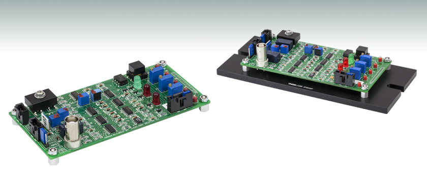
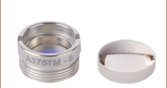
IP250-BV
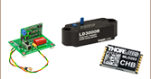
Application Idea
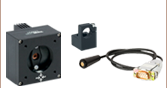
IP500 with IP500P

Please Wait

IP250-BV
- 250 mA 青色半導体レーザードライバ
- LED駆動用にも推奨
- 入力電力±12 VDC @ 275 mA
- 制御範囲: 0~±250 mA (CC)、5 μA~2 mA (CW)
- 0 ~10 V アナログ変調帯域幅: DC ‐ 50 kHz
- Vop が5 Vを超えるレーザに適した製品
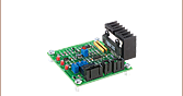
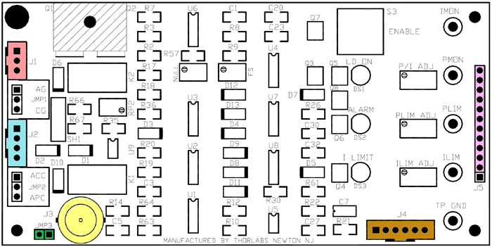
IP250-BVは250 mA (中出力)対応のボード型半導体レーザーコントローラで、青色と青紫色の半導体レーザ などの高い動作電圧が必要な半導体光源用の製品です。このドライバはPCBボードの形状で、お客様のシステムに簡単に組込むことができます。カソードコモン(カソード接地)半導体レーザのピン配置にのみ対応し、定電流か定光出力モードでレーザを制御します。ドライバは様々な安全要件に準拠した回路を内蔵しており、それと同時に半導体レーザを保護するための回路も搭載しています。
この製品の主な用途は、PCB基板のままの状態または上位ユニッ トへの組み込み状態で、青色または青紫色の半導体レーザを精密制御することです。なお、いずれの場合もDC電源のご用意と、ドライバと半導体レーザの接続 はお客様側にて行なっていただくことになります。また、特定の半導体レーザに必要となる適切なリミット値の設定に関しても、お客様の責任のもとに行なっていただきます。
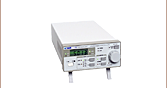
IP500
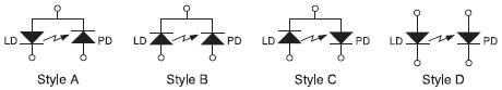
- ピン配置A、B、C、D(「IP500仕様」タブ参照)に対応
- LED駆動用にも推奨
- 定電流と定光出力モードで動作
- 電流および光出力のリミット値の設定が可能
- アイドル動作中はデバイス保護の為に半導体レーザ入力を短絡
- レーザ接続がオープンまたは逆方向時、自動警告と電流遮断
- 入力と出力ケーブルが付属
- 半導体レーザ電流、モニタ用フォトダイオード電流、電流リミット、出力リミットの設定値にテストポイント
IP500は、500 mA対応のボード型のドライバです。こちらの汎用的なデバイスは、5.6 mmまたは9 mmのTO-Canパッケージの半導体レーザを容易かつ安全に制御します。このドライバはモニタ用フォトダイオードが付いたA、B、C、Dのピン配置に対応します(詳細はマニュアルをご覧ください)。定電流、定光出力のいずれのモードにおいても、このドライバは 基板上あるいはリモートスイッチ接続でENABLE状態にすることができます。リモートインターロック用とリモートモニタ用の端子が有り、必要な全てのケーブルが製品に付属しています。
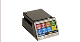
IP500P
IP250-BVとIP500は両製品共に、 マウントプレートIP500Pにより光学テーブルまたはブレッドボードに取り付けることができます。このアルミニウム製プレートの両端中央にネジ用のスロットがあり、 さらにプレートとボード間6.4 mmの隙間を作るための取付けスペーサ用の4個の#4-40穴があります。その他に2つの取付け穴(1つは#8-32で、もう1つはM4)があるので、標準のポストに取付け可能です。IP250-BVとIP500は絶縁体上に固定できますが、このプレートを使うと光学テーブルやブレッ ドボードに取り付けることができます。
| IP250-BV Specifications | |
|---|---|
| Input Power Requirements | ±12 VDC @ 275 mA |
| Constant Current Mode | |
| Control Range | 0 to ±250 mA |
| Setting Accuracy | ±0.5 mA |
| Compliance Voltage | 8.0 VDC (Max) |
| Ripple & Noise (10 Hz - 10 MHz) | <10 μA RMS |
| Short-Time Fluctuations | <50 μA |
| Temperature Coefficient | <100 ppm/°C |
| Drift (<10 Hz Over 30 minutes) | <100 μA |
| Limit Adjust Range | 0 to 250 mA |
| Limit Accuracy | ±1% of Limit Setpoint |
| Constant Power Mode | |
| Control Range Photo Diode Current | 5 μA to 2 mA |
| Setting Accuracy | ±2 μA |
| Drift (<10 Hz Over 30 minutes) | <1 μA |
| Limit Adjust Range | 0 to 2.5 mA |
| Limit Accuracy | ±2 μA |
| Analog Modulationa / Control Voltage | |
| Input Resistance | 10 kΩ |
| Bandwidth | DC to 50 kHz |
| Transfer Function (ACC Mode) | 25 mA/V |
| Input Range | 0 to 10 V |
| Analog Monitor Outputsb | |
| Ilim | 0 to 250 mV = 0 to ±250 mA |
| ILD | 0 to 250 mV = 0 to ±250 mA |
| IPD | 0 to 2.0 V = 0 to 2.0 mA |
| Plim | 0 to 2.5 V = 0 to 2.5 mA |
| Physical Specifications | |
| Dimensions (L x W x H) | 5.0" x 2.5" x 0.8" (127 mm x 63.5 mm x 20.3 mm) |
| Weight | 1.5 lbs (0.68 kg) |
IP250-BVのピンコード
| IP500 Specifications | |
|---|---|
| Input Power Requirements | ±5 VDC @ 600 mA (+4.75 to +5.25 V and -4.75 to -5.25 V) |
| Constant Current Mode | |
| Control Range | 0 to ±500 mA |
| Setting Accuracy | ±0.5 mA |
| Compliance Voltage | >3.0 VDC |
| Ripple & Noise (10 Hz - 10 MHz) | <10 μA RMS |
| Short-Time Fluctuations | <50 μA |
| Temperature Coefficient | <100 ppm/°C |
| Drift (<10 Hz Over 30 minutes) | <100 μA |
| Limit Adjust Range | 0 to 500 mA |
| Limit Accuracy | ±1% of Limit Setpoint |
| Constant Power Mode | |
| Control Range Photo Diode Current | 5 μA to 2 mA |
| Setting Accuracy | ±2 μA |
| Drift (<10 Hz Over 30 minutes) | <1 μA |
| Limit Adjust Range | 0 to >2.5 mA |
| Limit Accuracy | ±2 μA |
| Analog Modulationa / Control Voltage | |
| Input Resistance | 10 kΩ |
| Bandwidth | DC to 50 kHz |
| Transfer Function (ACC Mode) | 50 mA/V |
| Input Range | 0 to 10 V |
IP500のピンコード
IP250-BV/IP500コネクタの配置
| J5 Connector Type: Standard 0.1" Spaced Header | |
|---|---|
| Pin | Designation |
| J5-1 | TP Ground |
| J5-2 | ILIM Test Point |
| J5-3 | ILIM Adjust |
| J5-4 | IALARM |
| J5-5 | PLIM Test Point |
| J5-6 | PLIM Adjust |
| J5-7 | Alarm |
| J5-8 | PMON Test Point |
| J5-9 | P/I Adjust |
| J5-10 | Enable |
| J5-11 | IMON Test Point |
| J5-12 | 2.5 Vref |
| J4 Connector Type: Molex 70543-0005 | |
|---|---|
| Pin | Designation |
| J4-1 | Remote Enable Input |
| J4-2 | Remote Enable Return (Common to Ground) |
| J4-3 | Keylock Input |
| J4-4 | Keylock Return (Common to Ground) |
| J4-5 | Remote Interlock Input |
| J4-6 | Remote Interlock Return (Common to Ground) |
| J1 Connector Type: Molex 70543-0002 | ||
|---|---|---|
| Pin | Wire Color | Designation |
| J1-1 | Red | IP250-BV: +12 VDC In IP500: +5 VDC In |
| J1-2 | Black | Common |
| J1-3 | Yellow | IP250-BV: -12 VDC In IP500: -5 VDC In |
| J2 Connector Type: Molex 70543-0003 | |
|---|---|
| Pin | Designation |
| J2-1 | LDA (+) or LDC (-) |
| J2-2 | Ground LDC (+) or LDA (-) |
| J2-3 | Photodiode Cathode |
| J2-4 | Photodiode Anode |
| J3 Connector Type: BNC | |
|---|---|
| Pin | Designation |
| J3 | 0 - 10 VDC Modulate In |
| JMP3 Connector Type: Standard 0.1" Spaced Shorting Jumper (Supplied with Unit) | |
|---|---|
| Pin | Designation |
| JMP3-1 | Ground |
| JMP3-2 | Photodiode Cathode |
Click to Enlarge
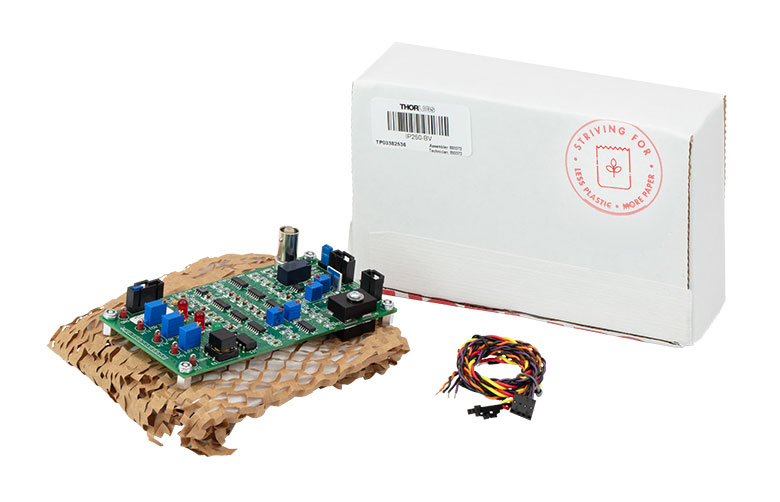
IP250-BV Packaging

Smart Pack
- Reduce Weight of Packaging
- Increase Usage of Recyclable Materials
- Improve Packing Integrity
- Decrease Shipping Costs
Thorlabs' Smart Pack Initiative is aimed at minimizing waste while providing adequate protection for our products. By eliminating any unnecessary packaging, implementing design changes, and utilizing eco-friendly materials, this initiative seeks to reduce the environmental impact of our product packaging.
The updated IP250-BV and IP500 packaging primarily consists of recycled paper and cardboard and weighs 22.78% and 21.58% less than the original packaging, respectively. This weight change results in 1.50 kg and 2.14 kg respective reductions in travel-based CO2 emissions per year, based on typical product sales.
As we move through our product line, we will indicate re-engineered, eco-friendly packaging with our Smart Pack logo, which can be seen above.
| Posted Comments: | |
EUIGEUN KIM
(posted 2023-05-15 16:12:22.323) Hi. I want to use IP500 : 500mA Universal Laser Diode Driver. But, i have one question.
I want to use my laser diode in my Lab. But my laser diode does not have monitor Photodiode. Thus, My Question is : Can i use IP500 Automatic Constant Current Mode(ACC) without monitor Photodiode? Is it okay that Jumper J2-3/2-4 opened?
When I look Manual, on the chapter : Alarms and TroubleShooting, it is written that I LIMIT indicator will turn ON when the laser injection current exceeds 95% of the ILIM setting... (Case) The Photodiode is not connected(in PMODE Operation : I think it may be Automatic Constant Power mode right?). I think there is no problem when i use ACC Mode.
In conclusion, I wonder if it is possible to use the IP500 when J2-3/J2-4 left unconnected(OPEN). ksosnowski
(posted 2023-05-16 05:14:43.0) Thanks for reaching out to Thorlabs. Unfortunately, IP500 cannot be used fully with Laser Diodes without a monitor PD. This driver can only be ON in one current, i.e. at its max current limit point, when used with a laser diode without the monitor photodiode. This means you can't regulate the laser current/power except by the limit potentiometer in this scenario. For this reason, we would generally consider IP500 not useful for lasers without a monitor PD, unless the setup can accept using the potentiometer to manually adjust the current each time. Jiri Kucera
(posted 2022-02-15 07:30:13.55) Hi! Is there a way of electronically switching between positive and negative current output?
Thank you!
Jiri cdolbashian
(posted 2022-03-08 10:48:46.0) Thank you for reaching out to us with this inquiry Jiri. Unfortunately, there isn't an inbuilt function which would allow you to remotely change the polarity of your current. The spec sheet does list both a positive and negative current available on output. This simply indicates the support of anode and cathode grounded diode packages. Jens Kießling
(posted 2021-03-21 03:40:15.347) Dear Thorlabs team,
we want to remotely operate the IP500 from a microcontroller and ideally need a pin which turns on the driver if e. g. shorted to GND and turns it off otherwise. We need an input that does not just behave like the switch on the device, but like a true enable input.
The J4-1 Remote Enable input is not very helpful for this, since one has no chance to know if the device is currently on, off or in alarm state, unless one reads out the LED, too.
Is any pin on J5 reserved for a true remote enable function or is there any other modification we can do to make the enable input behave like a true enable input and not use use the switch-logic?
Thanks in advance
Jens YLohia
(posted 2021-04-14 04:25:21.0) Hello Jens, thank you for contacting Thorlabs. Unfortunately, we are not able to recommend modifications to the part. That being said, Section 2.2.4 of the manual explains the different ways the IP500 can be used to make remote connections. The enable lines J4-1 and J4-2 mirror the onboard enable button. The keylock is included because of laser class 3B and higher requirements. To operate this a keylock must be installed for safety reasons. Basically, a key needs to be installed and on in order for the laser to turn on. The benchtop units implement this with the power switch. Either is okay as long as the key can be removed enforcing the unit cannot be enabled by anyone walking by. honglhk123
(posted 2013-08-07 15:50:39.983) Can I use DC pulse(square wave) for DC input?
Thanks. jlow
(posted 2013-08-08 15:56:00.0) Response from Jeremy at Thorlabs: You can use a switched-mode power supply but they are in general noisier than a linear power supply. The noise specification cannot be guaranteed in that case. jjurado
(posted 2011-02-01 17:57:00.0) Response from Javier at Thorlabs to jahr: Thank you very much for submitting your inquiry. We would recommend using the IP250-BV for driving the LP405-SF10, since the maximum compliance voltage of this driver is 8 VDC, and the operating voltage of the laser diode (5 VDC)exceeds that of the IP500 (3 VDC). The driver includes the necessary wire harnesses and sockets in order to connect to the laser diode, so they do not need to be ordered separately. Furthermore, it is recommended to use temperature control in order to preserve the lifetime of the laser pigtail, so a driver like the ITC4001 along with the LM9LP temperature controlled mount would be recommendable. I will contact you directly in case you have additional questions. jahr
(posted 2011-01-28 16:52:26.0) it looks as though either the IP250-BV or the IP500 is compatible with driving the LP405-SF10 LD. Is that correct? Do either of them come with a B connector? Do you sell those separately.
Thanks. |
半導体レーザーコントローラーセレクションガイド
Table 137Aと137B は、当社の半導体レーザ用コントローラおよびデュアル半導体レーザ/温度コントローラの主な仕様の一覧です。詳しい内容や仕様について、またはご注文の際には表内の型番をクリックしてご確認ください。
| Table 137A Current Controllers | ||||||
|---|---|---|---|---|---|---|
| Item # | Drive Current | Compliance Voltage | Constant Current | Constant Power | Modulation | Package |
| LDC200CV | 20 mA | 6 V | External | Benchtop | ||
| VLDC002 | 25 mA | 5 V | - | Int/Ext | OEM | |
| LDC201CU | 100 mA | 5 V | External | Benchtop | ||
| LD2000R | 100 mA | 3.5 V | - | External | OEM | |
| EK2000 | 100 mA | 3.5 V | - | External | OEM | |
| LDC202C | 200 mA | 10 V | External | Benchtop | ||
| KLD101 | 230 mA | ≤10 V | External | K-Cube® | ||
| IP250-BV | 250 mA | 8 Va | External | OEM | ||
| LD1100 | 250 mA | 6.5 Va | - | -- | OEM | |
| LD1101 | 250 mA | 6.5 Va | - | -- | OEM | |
| EK1101 | 250 mA | 6.5 Va | - | -- | OEM | |
| EK1102 | 250 mA | 6.5 Va | - | -- | OEM | |
| LD1255R | 250 mA | 3.3 V | - | External | OEM | |
| LDC205C | 500 mA | 10 V | External | Benchtop | ||
| IP500 | 500 mA | 3 V | External | OEM | ||
| LDC210C | 1 A | 10 V | External | Benchtop | ||
| LDC220C | 2 A | 4 V | External | Benchtop | ||
| LD3000R | 2.5 A | -- | - | External | OEM | |
| LDC240C | 4 A | 5 V | External | Benchtop | ||
| LDC4005 | 5 A | 12 V | Int/Ext | Benchtop | ||
| LDC4020 | 20 A | 11 V | Int/Ext | Benchtop | ||
| Table 137B Dual Temperature and Current Controllers | |||||||
|---|---|---|---|---|---|---|---|
| Item # | Drive Current | Compliance Voltage | TEC Power (Max) | Constant Current | Constant Power | Modulation | Package |
| VITC002 | 25 mA | 5 V | >2 W | - | Int/Ext | OEM | |
| ITC102 | 200 mA | >4 V | 12 W | Ext | OEM | ||
| ITC110 | 1 A | >4 V | 12 W | Ext | OEM | ||
| ITC4001 | 1 A | 11 V | >96 W | Int/Ext | Benchtop | ||
| CLD1010LPa | 1.0 A | >8 V | >14.1 W | Ext | Benchtop | ||
| CLD1011LPb | 1.0 A | >8 V | >14.1 W | Ext | Benchtop | ||
| CLD1015c | 1.5 A | >4 V | >14.1 W | Ext | Benchtop | ||
| ITC4002QCLd | 2 A | 17 V | >225 W | Int/Ext | Benchtop | ||
| ITC133 | 3 A | >4 V | 18 W | Ext | OEM | ||
| ITC4005 | 5 A | 12 V | >225 W | Int/Ext | Benchtop | ||
| ITC4005QCLd | 5 A | 20 V | >225 W | Int/Ext | Benchtop | ||
| ITC4020 | 20 A | 11 V | >225 W | Int/Ext | Benchtop | ||
当社では製品組み込み用あるいはラックマウントの半導体レーザ電流&温度コントローラ(組み込み用モジュール、PRO8電流コントロールモジュール、PRO8電流&温度コントロールモジュール)もご用意しております。