 Products Home
光ファイバー出力LED、マルチモードファイバー

- LEDs in the Visible or Near-IR Spectral Ranges
- Pigtailed, Ø9 mm TO-Can Package
- Ø400 µm or Ø1000 µm Core Multimode Fiber with SMA905 Connector
- Custom LED Pigtails Available
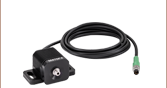
A fiber-pigtailed LED mounted to a PTLB1 bracket. The LED connector pins, clipped to 0.15" (3.8 mm), are inserted into an SR9F ESD protection / strain relief cable. The SR9F can then connect to a controller to drive the LED.
EP470S04
470 nm Pigtailed LED, Ø400 µm Multimode Fiber


Please Wait
Click to Enlarge
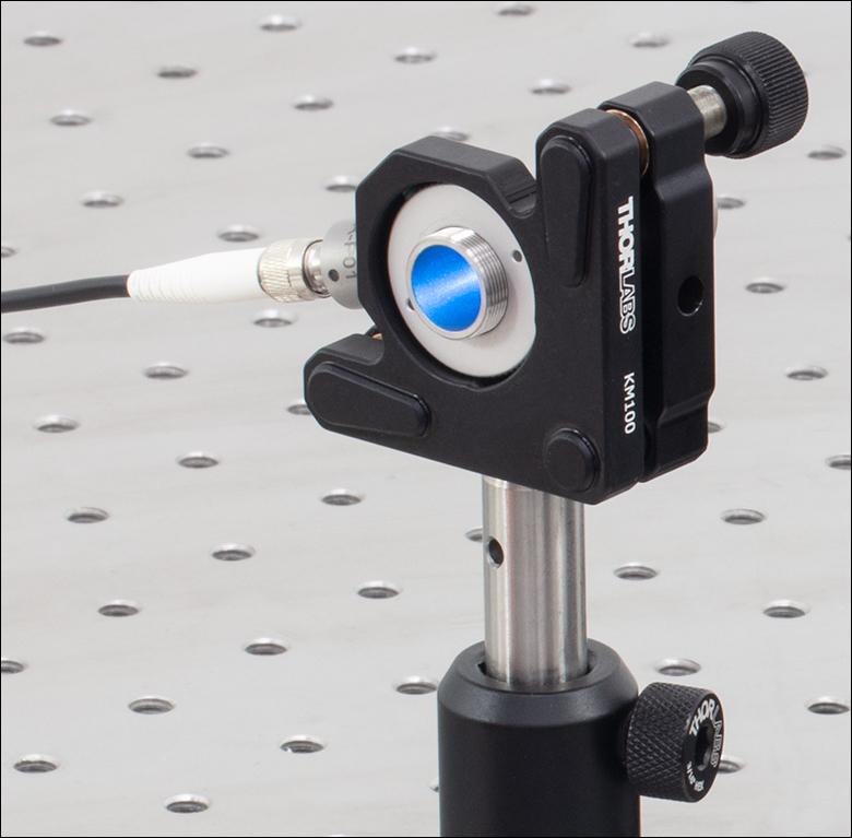
キネマティックマウントKM100内の半導体レーザ用マウントLDM9LP(画像にはありません)に取り付けられたLED EP470S04。LEDのファイバ出射光は反射型コリメータRC08SMA-P01でコリメートされています。推奨するマウントとドライバのリストは下表をご覧ください。
| アイコン等について | |
|---|---|
| 下記の表内の青いInfoアイコンをクリックすると、各製品の仕様と図面がご覧いただけます。 | |
 | 下記の表内の赤い資料アイコンをクリックすると、補足資料をダウンロードすることができます。 |
ピンコード
特長
- ピグテール付きLEDの中心波長:470 nm、590 nm、700 nm、810 nm
- LEDの出力パワー範囲:2 mW~100 mW
- SMA905コネクタ
- コア径Ø400 µmまたはØ1000 µm、長さ1 mのマルチモードファイバ
- カスタム仕様の光ファイバ出力LEDについては当社までお問い合わせください。
当社の発光ダイオード(LED)をマルチモードファイバに接続した製品で、その中心波長は470 nm~810 nmの可視または近赤外域です。Ø9 mm TOパッケージに入ったLEDに、コア径Ø400 µm(型番末尾S04)またはØ1000 µm(型番末尾S10)のマルチモードファイバが付いています。ファイバ先端にはSMA905コネクタが付いています。
各LEDはバットジョイントでマルチモードファイバに結合されています。この結合のプロセスでは、ファイバ端がエミッタにできるだけ近づくようにファイバーコネクタを配置し、ファイバ入力部での光損失を最小化して出力パワーを最大化するようにしています。各LEDの製造では、結合効率が最大になるよう、マルチモードファイバーピグテールのアライメントには細心の注意をはらっています。
仕様の詳細、スペクトル、およびL-I-Vグラフは、下表の青いアイコン(![]() )をクリックしてご覧ください。それらの情報は仕様書にも記載されており、型番横の赤いアイコン () をクリックするとご覧いただけます。各製品は発送前に検査を行い、製品個別のデータシートとともに発送いたします。こちらをクリックするとサンプルがご覧いただけます。
)をクリックしてご覧ください。それらの情報は仕様書にも記載されており、型番横の赤いアイコン () をクリックするとご覧いただけます。各製品は発送前に検査を行い、製品個別のデータシートとともに発送いたします。こちらをクリックするとサンプルがご覧いただけます。
LEDは静電気放電(ESD)に敏感です。製品の取扱いには十分にご注意ください。詳しくは静電気防止用アクセサリをご参照ください。
マウントとドライバについて
こちらのLEDはピン配列がEまたはHのピグテール付きパッケージに対応するすべてのマウントとドライバに取り付けられます。対応する半導体レーザ用マウントはこちらからご覧いただけます。また、半導体レーザ用の電流ドライバも幅広く取り揃えています。EP590Sxx、EP700Sxx、EP810Sxxには、CLD1010LPをお勧めしています。こちらはドライバとマウントが一体化された製品で、電流と温度の両方を制御できます。光ファイバー出力LEDは、当社のLED電流ドライバLEDD1B(別売り)に付属する接続ケーブルCAB-LEDD1に接続することも可能です。この場合、ケーブルCAB-LEDD1の裸のワイヤをLEDのピンにはんだ付けする必要があります。
ファイバの取り扱いについて
埃などの汚染物質が表面に付着する可能性が少しでもある場合は、ご使用前にピグテールパッケージを毎回必ずクリーニングすることをお勧めします。ファイバのクリーニング用品についてはこちらをクリックしてご覧ください。ファイバ先端の中心付近では光強度が非常に高くなる場合があるため、汚染物質が付着しているとファイバ先端が焼損する危険性があります。光ファイバ出力LEDに付いているコネクタはクリーニングしてからキャップを付けて出荷していますが、パッケージから取り出された後では周囲環境から汚染物が付着している可能性がございます。また、ファイバをクリーニングするとき、あるいはLEDを他のファイバに接続したり取り外したりするときは、LEDの電源を切ることをお勧めします。
| Posted Comments: | |
richard logan
(posted 2019-12-15 17:12:40.253) Is the output of the diode polarized? If the diode is damaged, how can it be removed from the pigtail? YLohia
(posted 2019-12-16 11:22:14.0) Thank you for contacting Thorlabs. The output from the fiber pigtail is not polarized. The LED chip cannot be removed from the pigtail. If the chip is damaged, unfortunately, the unit cannot be repaired. However, fiber/connector damage can be repaired in certain cases. user
(posted 2019-04-17 07:41:50.587) The title reads 1000 mA, but the specs inside the product box reads 500 mA with 750 mA maximum. So I bought a 1000 mA driver which now is of no use because I need a 500 mA driver. Please make sure you specify the correct values for the LED. YLohia
(posted 2019-04-29 11:03:29.0) Hello, thank you for contacting Thorlabs and my apologies for any issues caused by this. I had reached out to you directly at the time of this posting to gather more details. May I ask what driver you purchased? Most drivers should be able to supply variable current, which means that you should still be able to use the 1000mA driver. Also, would you be able to send us a picture of the part where a different max current (750mA) is specified on the spec sheet? Robson Sampaio
(posted 2019-04-05 07:31:21.763) Would it be possible to unmount the device and switch the LED? YLohia
(posted 2019-04-05 09:19:31.0) Hello, thank you for contacting Thorlabs. Unfortunately, this would not be possible as the package is sealed and the fiber is carefully aligned to maximize the coupling efficiency. However, we may be able to offer a custom solution if you require a different wavelength. Please email us at techsupport@thorlabs.com if you are interested in a custom solution with details about wavelength, fiber core size, minimum output power, and quantity. |
こちらのページでは当社が販売するすべてのLEDをご覧いただけます。More [+]をクリックすると、下の各LED製品の波長をご覧いただけます。
| Light Emitting Diode (LED) Selection Guide | ||||||
|---|---|---|---|---|---|---|
| Click Photo to Enlarge (Representative; Not to Scale) | 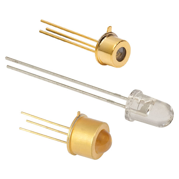 | 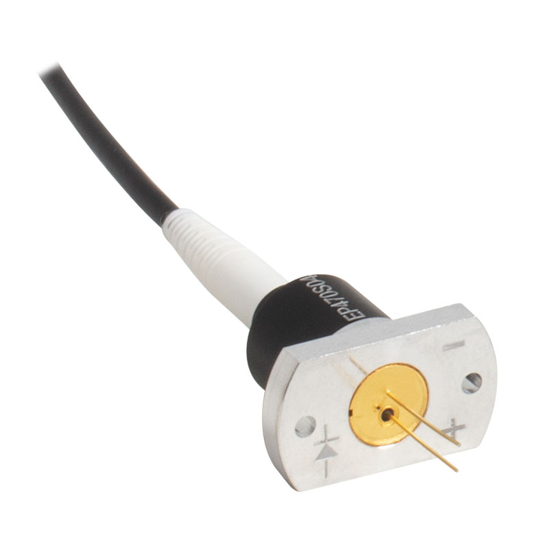 | 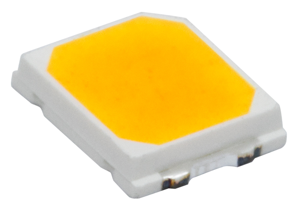 | 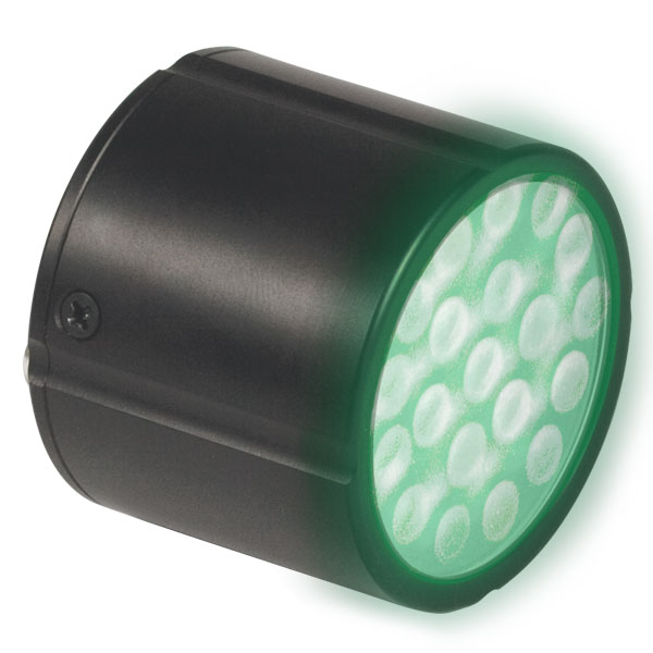 | 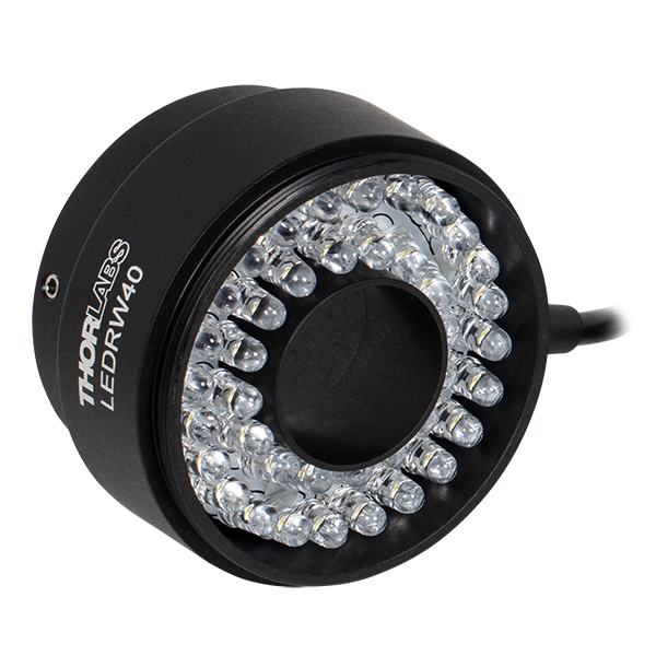 |  |
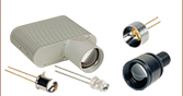
| Type | Unmounted LEDs | Pigtailed LEDs | LEDs in SMT Packages | LED Arrays | LED Ring Light | Cage-Compatible Diffuse Backlight LED |
| Light Emitting Diode (LED) Selection Guide | ||||||
|---|---|---|---|---|---|---|
| Click Photo to Enlarge (Representative; Not to Scale) | 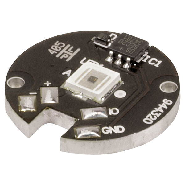 | 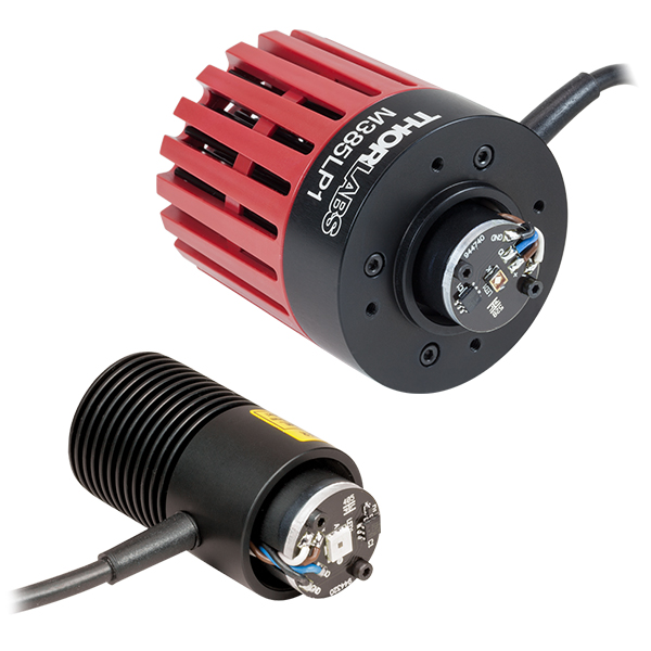 | 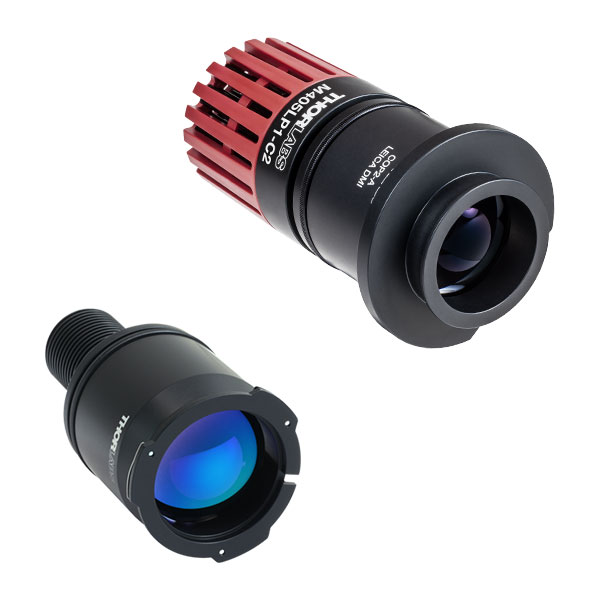 | 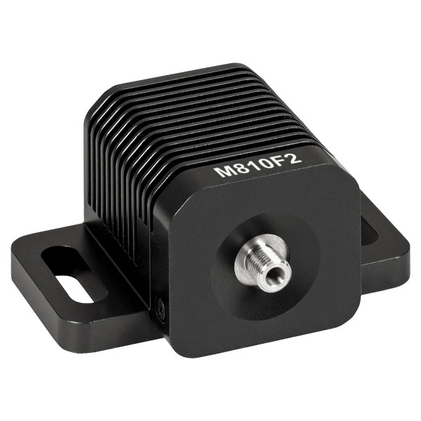 | 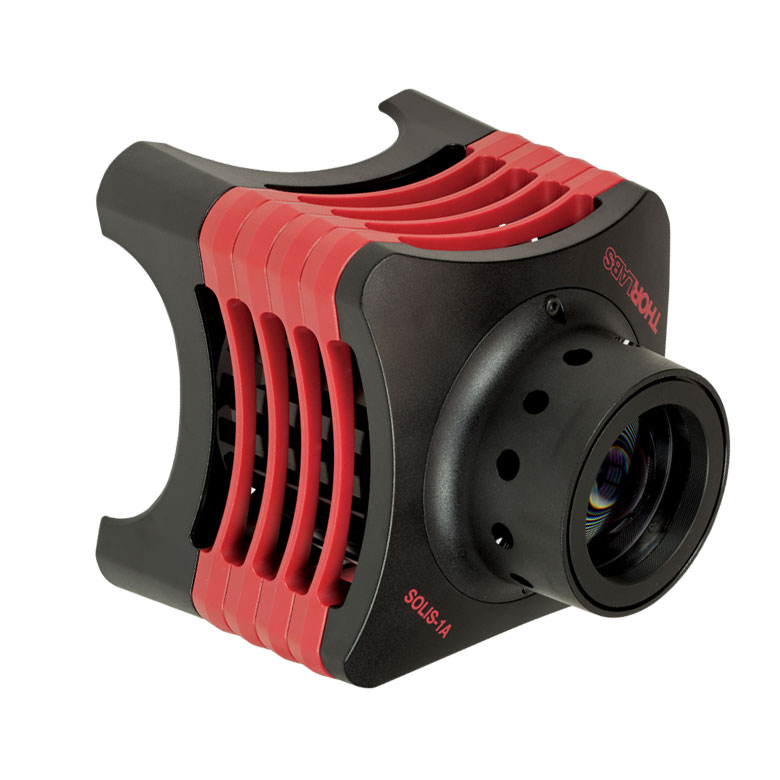 | 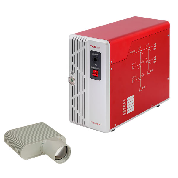 |
| Type | PCB- Mounted LEDs | Heatsink- Mounted LEDs | Collimated LEDs for Microscopyb | Fiber- Coupled LEDsc | High-Power LEDs for Microscopy | Multi-Wavelength LED Source Optionsd |
| Item # | Info | Center Wavelength (Typ.) | Output Power (Min)a | DC Forward Current (Max)a | Pin Code | Package | Fiber | Compatible Socket | Recommended Mount | Recommended Drivers |
|---|---|---|---|---|---|---|---|---|---|---|
| EP470S04 | 470 nm | 18 mW (at 500 mA) | 1000 mA | H | Ø9 mm TO Can, MM Pigtail, Ø400 µm Core | FP400ERT | S8060 or S8060-4 | LDM9LP | LDC210C, ITC4001, or LEDD1Bc | |
| EP470S10 | 100 mW (at 500 mA) | Ø9 mm TO Can, MM Pigtail, Ø1000 µm Core | FP1000ERT | |||||||
| EP590S04 | 590 nm | 3.5 mW (at 500 mA) | 600 mA | E | Ø9 mm TO Can, MM Pigtail, Ø400 µm Core | FP400ERT | CLD1010LPb or LDM9LP | |||
| EP590S10 | 18 mW (at 500 mA) | Ø9 mm TO Can, MM Pigtail, Ø1000 µm Core | FP1000ERT | |||||||
| EP700S04 | 700 nm | 2 mW (at 500 mA) | 600 mA | E | Ø9 mm TO Can, MM Pigtail, Ø400 µm Core | FP400ERT | ||||
| EP700S10 | 20 mW (at 500 mA) | Ø9 mm TO Can, MM Pigtail, Ø1000 µm Core | FP1000ERT |
| Item # | Info | Wavelength | Output Power (Min)a | DC Forward Current (Max)a | Pin Code | Package | Fiber | Compatible Socket | Recommended Mount | Recommended Drivers |
|---|---|---|---|---|---|---|---|---|---|---|
| EP810S04 | 810 nm | 16 mW (at 700 mA) | 1000 mA | E | Ø9 mm TO Can, MM Pigtail, Ø400 µm Core | FP400ERT | S8060 or S8060-4 | CLD1010LPb or LDM9LP | LDC210C, ITC4001, or LEDD1Bc | |
| EP810S10 | 90 mW (at 700 mA) | Ø9 mm TO Can, MM Pigtail, Ø1000 µm Core | FP1000ERT |