 Products Home
ステッピングモーター制御モジュール
- Two 50 W 2-Phase Bi-Polar Stepper Drive Outputs
- Motor Speeds Up to 3000 RPM
- 409 600 Microsteps per Revolution of Motor
- Seamless Operation with Thorlabs and 3rd Party Motors/Stages
Full Suite of Software Support
Tools Included
MST602


Please Wait
| Rack System Modules |
|---|
| 2-Channel Piezo Controller Module |
| 2-Channel Stepper Motor Controller Module |
| 2-Channel NanoTrak® Auto-Alignment Module |
| 2-Channel Brushless DC Motor Controller Module |
| USB Motion Control 19" Rack Chassis |
| 当社のすべてのラックシステムモジュールはラックマウントシャーシMMR601またはMMR602と共にお使いください。ラックマウントシャーシから外した状態のモジュールの個別の操作はできません。 |
特長
- 2つのステッピングモータ駆動チャンネル
- 高分解能マイクロステップ制御(微細位置決め用途向け)
- 速度制御された安定低速操作(速度に敏感な用途向け)
- 48 V/50 W(ピーク値)までの2相双極ステップをサポート
- 閉ループ位置決め用の差動エンコーダーフィードバック(QEP入力)
- 多軸構築への拡張用USBプラグ&プレイ
- モータ制御用I/Oポート(ジョグ、インターロック)
- Kinesis®制御用ソフトウェア一式が付属
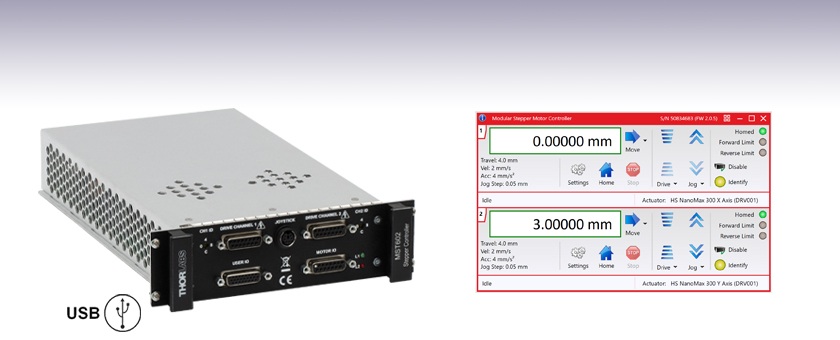
- 直感的操作が可能なグラフィック制御パネル
- 当社のほかのモーションコントローラとの完全統合(統合システム開発)
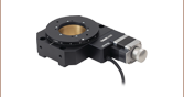
モジュールMST602は、モーションコントロール用19インチラックマウントシャーシMMR601またはMMR602とご使用いただけるように設計された2チャンネル、高分解能、ラックマウント型のステッピングモータードライバです。50 W以下で2相双極ステッピングモータを駆動するように設計され(エンコーダーフィードバック有り、または無し)、当社提供のすべてのステッピングモータ付きナノポジショニングアクチュエータやステージに対応します。また、多様なパワーとステップサイズの2相双極モータにも対応可能です。
こちらのステッピングモーターコントローラは、モーションコントロール用19インチラックシステムMMR601とMMR602向けに設計されています。最大6個までのステッピングモジュールMST602を装備できるため多軸モーションコントロール用途に拡張可能なモーションコントロールをご提供可能です。スタンドアローン型のコントローラについてはTable 1.1をご参照ください。
ラックマウントシャーシMMR601とMMR602をご使用の場合、USB接続によるPC操作が可能となります。多軸モーションコントロール用途の場合、標準的なUSBハブを介して複数のモジュールを1台のPCに接続することが可能ですできます。Kinesisソフトウェアと組み合わせることにより、短時間で使用前の設定が可能です。広範なKinesisプログラミング環境を使用すれば、より高度なカスタム仕様のモーションコントロールやシーケンスも可能となります。詳細は、「Kinesis ソフトウェア」および「Kinesisチュートリアル 」タブをご参照ください。
ステージの手動位置決めが可能な2軸ジョイスティックコンソール(型番MJC2)も別途ご用意しております。ジョイスティックコンソールの使用についての詳細は、赤いアイコン(![]() )からご覧いただけるマニュアルでご確認いただけます。
)からご覧いただけるマニュアルでご確認いただけます。
ケーブルについて
アクチュエータやステージをコントローラに接続するケーブルはアクチュエータやステージに付属しており、コントローラには付属しておりません。交換用のケーブルについてのお問い合わせは当社までご連絡ください。
| Table 1.1 Other Stepper Motor Controllers | ||
|---|---|---|
| K-Cube® Single-Channel Controller | 1-, 2-, and 3-Channel Benchtop Controller | Modular 2-Channel Rack System Module |
モジュールの仕様
| Motor Drive Connector (15-Pin D-Type Female) Per Channel | |
|---|---|
| 2 Phase Bipolar Motor Drive Output | Forward, Reverse Limit Switch Inputs |
| Differential Quadrature Encoder (QEP) Input | Encoder 5 V (with Ground) |
| Motor Control Connector (15-Pin D-Type Female) | |
| Jog Forward/Back Input | TTL Level |
| Enable/Disable Interlock (Per Channel) | Connect to Return to Operate Motor |
| User 5 V (with Ground) 100 mA Max | |
| User I/O Connector (26-Pin D-Type Female) | |
| 4 Logic Inputs | TTL Level |
| 4 Logic Outputs | Open Collector |
| Trigger Input | TTL Level |
| Trigger Output | Open Collector |
| 2 Analogue Inputs | Single Ended 0 - 10 V (12-bit) |
| Motor Resolution | |
| 2048 Microsteps per Full Step | |
| For 200 Step Motor - 409 600 Microsteps/Rev | |
| For 24 Step Motor - 49 152 Microsteps/Rev | |
| Motor Drive Voltage | Up to 48 V |
| Motor Drive Power | Up to 50 Wpeak/25 Wave |
| Motor Speeds | Up to 3000 RPM (200 Full Step Motor) |
| Encoder Feedback Bandwidth | 500 kHz |
| General | |
| Housing | Single Rack System Bay |
| Dimensions (W x D x H) | 190 x 270 x 50 mm (7.5" x 10.6" x 2") |
| Weight | 1.5 kg (3.3 lbs) |
対応するモータの仕様
| Specification | Value |
|---|---|
| Peak Powers | 5 to 50 W |
| Average Power | 25 W Maximum |
| Step Angle Range | 20° to 1.8° |
| Coil Resistance (Nominal) | 4 to 15 Ω |
| Coil Inductance (Nominal) | 4 to 15 mH |
| Rated Phase Currents (Nominal) | 100 mA to 1 A |
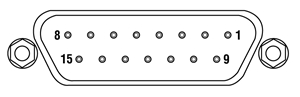
モータI/Oコントローラ
Dタイプメス型
| Pin | Description | Return | Pin | Description | Return | Pin | Description | Return |
|---|---|---|---|---|---|---|---|---|
| 1 | User 5 V I/O | 9 | 6 | Channel 2 Emergency Stop Daisy Chain Link Returnb | 14 | 11 | Channel 2 Jog Backwardsa | 9 |
| 2 | Channel 1 Jog Forwardsa | 9 | 7 | Channel 2 Enable Returnb | 15 | 12 | Channel 1 Emergency Stop Daisy Chain Linkb | 4 |
| 3 | Channel 2 Jog Forwardsa | 9 | 8 | Not Used | - | 13 | Channel 1 Enableb | 5 |
| 4 | Channel 1 Emergency Stop Daisy Chain Link Returnb | 12 | 9 | User 0V | - | 14 | Channel 2 Emergency Stop Daisy Chain Linkb | 6 |
| 5 | Channel 1 Enable Returnb | 13 | 10 | Channel 1 Jog Backwardsa | 9 | 15 | Channel 2 Enableb | 7 |
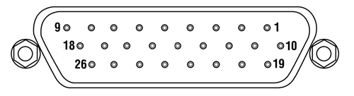
ユーザI/Oコントローラ
Dタイプメス型
| Pin | Description | Return | Pin | Description | Return | Pin | Description | Return |
|---|---|---|---|---|---|---|---|---|
| 1 | Digital I/P 1 | 19 | 10 | Digital O/P 1 | 19 | 19 | Digital Ground 1 (0 V)a | - |
| 2 | Digital I/P 2 | 19 | 11 | Digital O/P 2 | 19 | 20 | Ext Trigger I/P | 22 |
| 3 | Digital I/P 3 | 19 | 12 | Digital O/P 3 | 19 | 21 | Ext Trigger O/P | 22 |
| 4 | Digital I/P 4 | 19 | 13 | Digital O/P 4 | 19 | 22 | Digital Ground 2 (0 V)a | - |
| 5 | Channel 1 RS232 TX | - | 14 | Channel 2 RS232 TX | - | 23 | 5 V User O/P (50 mA Max.) | - |
| 6 | Channel 1 RS232 RX | - | 15 | Channel 2 RS232 RX | - | 24 | Reserved for Future Use | - |
| 7 | Not Used | - | 16 | Reserved for Future Use | - | 25 | Reserved for Future Use | - |
| 8 | Channel 2 Analog I/P (+)b | 17 | 17 | 0 V (Analog Rtn)b | 8 | 26 | Analog Ground (0 V)a,c | - |
| 9 | Channel 1 Analog I/P (+)b | 18 | 18 | 0 V (Analog Rtn)b | 9 |
ドライブチャンネル用コネクタ
Dタイプメス型
| Pin | Description | Pin | Description | Pin | Description |
|---|---|---|---|---|---|
| 1 | Encoder A +ve | 6 | Not Used | 11 | 0 V User |
| 2 | Encoder A -ve | 7 | Phase B - | 12 | Reserved for Future Use |
| 3 | Encoder B +ve | 8 | Phase A - | 13 | Reserved for Future Use |
| 4 | Encoder B -ve | 9 | CW Limit Switch | 14 | Phase B + |
| 5 | 5 V User | 10 | CCW Limit Switch | 15 | Phase A + |
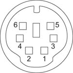
ハンドセット
ミニDINメス型
| Pin | Description | Pin | Description |
|---|---|---|---|
| 1 | RX (Controller Input)/RS232 | 4 | Supply Voltage for Handset 5V |
| 2 | Ground | 5 | TX (Controller Output) |
| 3 | Ground | 6 | Ground |
ソフトウェア
Kinesisバージョン1.14.52
このKinesisソフトウェアパッケージには、当社のKinesisシステムコントローラを制御するためのGUIが含まれています。
下記もご用意しております。
- 通信プロトコル

Figure 58A KinesisソフトウェアのGUI画面
当社のKinesis®ソフトウェアパッケージを用いて、当社の様々なモーションコントローラを駆動することができます。このソフトウェアは小型で低出力のシングルチャンネルドライバ(K-Cube®など)から、高出力でマルチチャンネルのベンチトップ型ユニットやモジュール型の19インチラックナノポジショニングシステム(ラックシステムMMR60x)まで、当社Kinesisシリーズの様々なモーションコントローラの制御用にご使用いただけます。
Kinesisソフトウェアでは.NETコントロールを使用できるため、最新のC#、Visual Basic、LabVIEW™、あるいはその他の.NET対応言語を使用してカスタムプログラムを作成することができます。.NETフレームワークの使用を想定していないアプリケーションのために、ローレベルのDLLライブラリも含まれています。中央シーケンスマネージャ(Central Sequence Manager)は、当社のすべてのモーションコントロール用ハードウェアの統合と同期の機能をサポートしています。
この共通のソフトウェアプラットフォームにより、ユーザは単一のソフトウェアツールを習得するだけで、あらゆるモーションコントロールデバイスを1つのアプリケーション内で組み合わせて使用することができます。このように1軸システム用から多軸システム用までのあらゆるコントローラを組み合わせ、それら全てを1台のPCの統合されたソフトウェアインターフェイスから制御できます。
このソフトウェアパッケージには2つの使い方があります。1つはGUI(グラフィカルユーザーインターフェイス)ユーティリティを用いる方法で、コントローラの到着後すぐに直接的な操作と制御を行なうことができます。もう1つは一連のプログラミングインターフェイスを用いる方法で、ご希望の開発言語によりカスタム仕様の位置決めやアライメント用のプログラムを簡単に作成することができます。
| Posted Comments: | |
user
(posted 2025-03-08 20:02:43.003) Hi, we bought three 2-channel MST602 to control two NanoMax stage (MAX311) with six DRV208 Stepper Motor Actuators. The rack system is MMR602.
Now the problem is that only two MST602 are connected and shown in the Kinesis Software.
We found that pin 8 of the Motor I/O Connector was stuck due to the probe. However, according to the pin diagram, pin 8 is not in use. We are unsure whether this is an issue.
I look forward to receiving your reply and I can show you the picture of the equipment. Thank you!
Best regards,
Xu Daehan Choi
(posted 2023-04-06 17:15:59.613) Hi, We recently bought three 2-channel step motor driver module(MST602) and three 2-channel piezo driver module(MPZ601) to connect with NanoMax stage(MAX683/m).
We downloaded APT software to connect with our lab PC, but there are two problems.
1. When I'm trying to associate stage using APT config, channel setting is disabled. So I can't associate channel 2s with our NanoMax stage. (And in APT user, all the channel 2 shows "stage : unknown" message.)
2. Piezo controller modules are not shown on the Motor list. Is there no problem if I use piezo module without associating the stage?
I look forward to receiving your reply.
Best regards,
Daehan Choi JReeder
(posted 2023-04-11 05:13:22.0) Thanks for your enquiry. I am reaching out to you to discuss this with you further. For the MPZ601, there is no need to select the correct actuator using the APT config as the relevant parameters for a piezo can be set within the settings or are detected automatically by the software. José de-Oliva-Rubio
(posted 2023-03-15 08:20:57.717) Dear Sir or Madam,
We have on set of MAX601 with piezos and step actuators, They're so old (I don't remember exactly but they may date from 2009) that the controllers are CVI/Melles Griot.
Also we've recently purchased an additional pair of MAX601 with built-in piezos and step actuators for an additional measurement setup.
We control the platforms from Matlab using an in-house program to command the axis with a wireless game pad.
The problem is that according Mathworks they are going to discontinue the support of ActiveX controls in future versions of Matlab. Thus, being the correspondent functions (as for example actxcontrol) no longer available.
Would you kindly provide me the information needed to handle the platforms from Matlab with an alternative method? Because despite the anouncement from Mathworks (which was included in the 2019b release of Matlab) you still recommend the use of ActiveX controls to handle the platforms from Matlab.
Regards,
José do'neill
(posted 2023-03-16 01:21:40.0) Response from Daniel at Thorlabs: Thanks you for your feedback. Our Kinesis software has .NET based DLLs rather than the ActiveX DLLs that are included in the older APT software. I will reach out to you directly to discuss you particular application. leslie.bullock
(posted 2018-05-16 14:07:00.867) Doh! It might have assisted, if I had included my e-mail address for my previous post!
Kind Regards. - Les. user
(posted 2018-05-16 14:03:48.093) Hi.
I’m utilising LabVIEW to control the following items, 3 x MST602, installed into a MMR601, along with a MAX604/M 6-Axis stage.
Currently, I don’t have the physical hardware available, hence I’ve configured the Kinesis simulator with two BSC103 3 Channel Motor Controllers, these controllers in themselves are marked as ‘obsolete’, but they are the nearest I can find, in relation to the MST602 APT Stepper Motor Control Modules.
Anyway, moving on from this issue with the Kinesis simulator product selection, I can get the Kinesis User GUI software to satisfactory communicate with the Kinesis simulator.
However, when I configure LabVIEW to utilise the Kinesis software provided .dll to implement .NET control ‘calls’, I get a reported error of “No Suitable Devices Found”, consequently checking the Kinesis simulator, there isn’t any connection activity, which you do see, when the Kinesis User GUI software connects to the Kinesis simulator.
So I’ve found a similar issue on the NI forum (https://knowledge.ni.com/KnowledgeArticleDetails?id=kA00Z0000019RKySAM) , and have made the users suggested changes, but to no avail.
So my query is, as I’m wanting to use the Kinesis simulator, and not the actual hardware platform, do I have to invoke a connection to the simulator first, prior to attempting to establish a connection from “BenchtopStepperControl.NET”?
I note that there is a SimulationManager (within “Thorlabs.MotionControl.DeviceManagerCLI.dll”), but it doesn’t contain any public constructors, so it doesn’t appear that I can access the Kinesis simulator in that way.
So if you could kindly provide me with a detail explanation of the procedure, or an example of LabVIEW code that would facilitate the utilisation of the Kinesis simulator, I would be most grateful.
Thanks and Kind Regards. – Les. bhallewell
(posted 2018-05-18 05:13:00.0) Response from Ben at Thorlabs: Thank you for your feedback. I see you've also emailed us & I've got back to you with a solution on connecting to this hardware.
The methods for use of the Simulator can be found within the Kinesis .NET help file > DeviceManagerCLI.dll.
Within the Simulator, when selecting the BSC* series you can select Hardware Type revision which will enable you to simulate the latest hardware types. The Modular Stepper Controller is a Stepper Controller based on the Benchtop Stepper Motor (BSC103, BSC102, BSC101, BSC203, BSC202, BSC201) device used in the Modular Rack (MMR601). The Stepper Controller uses the Benchtop Stepper Motor (BSC103, BSC102, BSC101, BSC203, BSC202, BSC201) modules for it's functionality. gliang1
(posted 2015-03-31 16:20:55.753) Dear Sir/Madam,
Could you send me an older version of the APT software so that I can install it in my Windows XP system? Thanks!
Best regards,
Guozhen msoulby
(posted 2015-03-31 06:27:59.0) Response from Mike at Thorlabs: We stopped supporting windows XP for our APT software since 2013; all of our latest versions will only operate on windows 7 operating systems or later. However I have contacted you directly with details on how to download the very last version of APT that is compatible with Windows XP. user
(posted 2014-05-14 16:01:59.73) Are you only support Windows platforms? And than only via ActiveX? Please make a simple dll (.so) shared libary next time. msoulby
(posted 2014-05-14 11:08:42.0) Response from Mike at Thorlabs: Currently our APT package is only supported on windows based operating systems, back to windows XP. If you are using a non-windows platform then you will need to use our low level communications protocol over a virtual serial port to communicate with the controller, this document can be view at the following link http://www.thorlabs.de/software/apt/APT_Communications_Protocol_Rev_11.pdf We also have an APT.dll available which does not use ActiveX; if you can provide us with an email address we would be happy to send you this .dll and some details on its use. JCY
(posted 2014-02-04 13:49:37.17) Hello, do the auto alignment features of the MMR601/MNA601/R work equally well (at all?) with the MST602 stepper modules. I need the extra travel/flexibility of stepper motor/drives.
Thanks,
Jonathan msoulby
(posted 2014-02-05 04:29:12.0) Response from Mike at Thorlabs: The MNA601 can only provide piezo motion in response to the feedback signal. This signal can either be optical from the OPTICAL/PIN IN photodiode or an analogue electrical signal 0-10V input on the SIG IN connector. The MNA601 is only able to scan and track within the range of piezo travel provided by the stage you are driving. The stepper motors are there to provide coarse adjustments to get the stage close enough so that the piezo actuators can refine the alignment. If you need to use the stepper motors to initially find the signal then a dark search raster scan can be developed in a program such as LabView or Matlab to find the coarse position. Once this is position is found you can switch the program to the piezos and Nanotrak to optimise and maintain this alignment. tcohen
(posted 2012-07-12 13:25:00.0) Response from Tim at Thorlabs to Michal: Thank you for your inquiry. All of the Thorlabs Rack System Modules require the use of the MMR601 for operation. nejbauer
(posted 2012-07-12 12:20:58.0) Hello,
It is possible to operate MST601 unit without having MMR601 Rack system?
Best regards,
Michal Nejbauer jjurado
(posted 2011-05-27 10:27:00.0) Response from Javier at Thorlabs to i.abbadi: Thank you for your reply.It looks like you can use the SetAbsMovPos and MoveAbsolute commands. I was not able to contact you directly via e-mail regarding your last inquiry. Please contact us at techsupport@thorlabs.com so that we can discuss your application. i.abbadi
(posted 2011-05-27 05:43:14.0) hi , thanks for your response , well i want to command the rotation of two motors at the same time ;im looking for the instruction how to set its position without turning or make a boolean command to move the motors after setting there positions before , im using a BSC102 and the motors are connected to its channels jjurado
(posted 2011-05-26 10:12:00.0) Response from Javier at Thorlabs to i.abbadi: Thank you very much for contacting us. The LLSetGetDigOPs method sets or gets the status of the digital outputs on the APT unit associated with the ActiveX control instance. If the bSet parameter is set to TRUE, the method sets the output state. If bSet is set to FALSE, the method returns the output state. I will contact you with more details about this method and I will also like to get additional info about your application. You can also find more information in the Help section of the APT software: Start > All Programs > Thorlabs > APT > Help > APT Server Help > Programming Guide. i.abbadi
(posted 2011-05-26 06:54:14.0) hi,we have the MST601 and we could not control it by Labview. can we have more information about the LLSetGetDigOPs commands? Thorlabs
(posted 2010-10-20 16:15:29.0) Response from Javier at Thorlabs to jouko.viitanen: the User I/O connections of the MST601 are intended for use with ActiveX compatible platforms such as Visual Basic, LabVIEW, etc. You would use the low level commands LLSetGetDigOPs and LLSetGetHostDigOPs, which talk to the motherboard I/O instead of the separate card I/Os. I will contact you directly with more information about these commands. jouko.viitanen
(posted 2010-10-19 12:54:47.0) We have your MST601 stepper motor controller in the MMR rack. The controller works ok. I would also like to use the the 4 digital output bits available from the "User I/O" connector of the MST601. However, they are not available from the GUI panel, and I did not find any hints from the APT configurator utility, if some other driver needs to be installed in order to be able to switch the bits on/off in the APT user interface. |